Multichannel STM-1 Port Adapter Installation and Configuration on Cisco 3900 Series Integrated Services Routers
Bias-Free Language
The documentation set for this product strives to use bias-free language. For the purposes of this documentation set, bias-free is defined as language that does not imply discrimination based on age, disability, gender, racial identity, ethnic identity, sexual orientation, socioeconomic status, and intersectionality. Exceptions may be present in the documentation due to language that is hardcoded in the user interfaces of the product software, language used based on RFP documentation, or language that is used by a referenced third-party product. Learn more about how Cisco is using Inclusive Language.
- Updated:
- March 20, 2015
Chapter: STM1 Port Adapter HIG Conf Preparation
Preparing for Installation
This chapter describes the general equipment, safety, and site preparation requirements for installing the SM-1-STM1. This chapter contains the following sections:
•![]() Minimum Software and Hardware Requirements
Minimum Software and Hardware Requirements
•![]() Checking Hardware and Software Compatibility
Checking Hardware and Software Compatibility
Required Tools and Equipment
You need the following tools and parts to install a SM-1-STM1. If you need additional equipment, contact a service representative for ordering information.
•![]() SM-1-STM1SMI or SM-1-STM1MM
SM-1-STM1SMI or SM-1-STM1MM
•![]() One SC-type duplex or two SC-type simplex, multimode or single-mode optical fiber cables to connect the interface with the network. (Single-mode and multimode optical fiber cables for the SM-1-STM1 are not available from Cisco Systems but are available from commercial cable vendors. For information about optical fiber cables, see the "Cables, Connectors, and Pinouts" section on page 1-8.)
One SC-type duplex or two SC-type simplex, multimode or single-mode optical fiber cables to connect the interface with the network. (Single-mode and multimode optical fiber cables for the SM-1-STM1 are not available from Cisco Systems but are available from commercial cable vendors. For information about optical fiber cables, see the "Cables, Connectors, and Pinouts" section on page 1-8.)
•![]() Number 2 Phillips or a 3/16-inch flat-blade screwdriver
Number 2 Phillips or a 3/16-inch flat-blade screwdriver
•![]() Your own electrostatic discharge (ESD)-prevention equipment or the disposable grounding wrist strap included with all upgrade kits, field-replaceable units (FRUs), and spares
Your own electrostatic discharge (ESD)-prevention equipment or the disposable grounding wrist strap included with all upgrade kits, field-replaceable units (FRUs), and spares
•![]() Antistatic mat
Antistatic mat
•![]() Antistatic container
Antistatic container
Minimum Software and Hardware Requirements
This section indicates the recommended minimum Cisco IOS software release required to use the SM-1-STM1 in supported platforms.
For the latest releases supporting the SM-1-STM1, refer to the "Checking Hardware and Software Compatibility" section.
Checking Hardware and Software Compatibility
To check the minimum software requirements of Cisco IOS software with the hardware installed on your router, Cisco maintains the Software Advisor tool on Cisco.com. This tool does not verify whether modules within a system are compatible, but it does provide the minimum IOS requirements for individual hardware modules or components.

Note ![]() Access to this tool is limited to users with Cisco.com login accounts.
Access to this tool is limited to users with Cisco.com login accounts.
To access Software Advisor, go to: http://www.cisco.com/en/US/support/tsd_most_requested_tools.html.
Choose a product family or enter a specific product number to search for the minimum supported software release needed for your hardware.
Safety Guidelines
This section provides safety guidelines that you should follow when working with any equipment that connects to electrical power or telephone wiring.
Warning Definition
Safety warnings appear throughout this publication in procedures that, if performed incorrectly, may cause bodily harm. A warning symbol precedes each warning statement.


Electrical Equipment Guidelines
Follow these basic guidelines when working with any electrical equipment:
•![]() Before beginning any procedures requiring access to the chassis interior, locate the emergency power-off switch for the room in which you are working.
Before beginning any procedures requiring access to the chassis interior, locate the emergency power-off switch for the room in which you are working.
•![]() Disconnect all power and external cables before moving a chassis.
Disconnect all power and external cables before moving a chassis.
•![]() Do not work alone when potentially hazardous conditions exist.
Do not work alone when potentially hazardous conditions exist.
•![]() Never assume that power has been disconnected from a circuit; always check.
Never assume that power has been disconnected from a circuit; always check.
•![]() Do not perform any action that creates a potential hazard to people or makes the equipment unsafe; carefully examine your work area for possible hazards such as moist floors, ungrounded power extension cables, and missing safety grounds.
Do not perform any action that creates a potential hazard to people or makes the equipment unsafe; carefully examine your work area for possible hazards such as moist floors, ungrounded power extension cables, and missing safety grounds.
Preventing Electrostatic Discharge Damage
Electrostatic discharge (ESD) damage, which can occur when electronic cards or components are improperly handled, results in complete or intermittent failures. Service modules and processor modules comprise printed circuit boards that are fixed in metal carriers. Electromagnetic interference (EMI) shielding and connectors are integral components of the carrier. Although the metal carrier helps to protect the board from ESD, use a preventive antistatic strap during handling.
Following are guidelines for preventing ESD damage:
•![]() Always use an ESD wrist or ankle strap and ensure that it makes good skin contact.
Always use an ESD wrist or ankle strap and ensure that it makes good skin contact.
•![]() Connect the equipment end of the strap to an unfinished chassis surface.
Connect the equipment end of the strap to an unfinished chassis surface.
•![]() Handle carriers by available handles or edges only; avoid touching the printed circuit boards or connectors.
Handle carriers by available handles or edges only; avoid touching the printed circuit boards or connectors.
•![]() Place a removed circuit board component-side-up on an antistatic surface or in a static shielding container. If you plan to return the component to the factory, immediately place it in a static shielding container.
Place a removed circuit board component-side-up on an antistatic surface or in a static shielding container. If you plan to return the component to the factory, immediately place it in a static shielding container.
•![]() Avoid contact between the printed circuit boards and clothing. The wrist strap only protects components from ESD voltages on the body; ESD voltages on clothing can still cause damage.
Avoid contact between the printed circuit boards and clothing. The wrist strap only protects components from ESD voltages on the body; ESD voltages on clothing can still cause damage.
•![]() Never attempt to remove the printed circuit board from the metal carrier.
Never attempt to remove the printed circuit board from the metal carrier.

Laser and LED Safety
The single-mode transmitter in the module uses a small laser to transmit the light signal to the network ring. Keep the transmit port covered whenever a cable is not connected to it. Although multimode transceivers typically use LEDs for transmission, it is good practice to keep open ports covered and avoid staring into open ports or apertures. The single-mode aperture port contains a laser warning label, as shown in Figure 2-1.
Figure 2-1 Laser Warning Labels for the SM-1-STM1-SM-C


Warning ![]() Class 1 laser product. Statement 1008.
Class 1 laser product. Statement 1008.
Warning ![]() Invisible laser radiation may be emitted from disconnected fibers or connectors. Do not stare into beams or view directly with optical instruments. Statement 1051.
Invisible laser radiation may be emitted from disconnected fibers or connectors. Do not stare into beams or view directly with optical instruments. Statement 1051.
The multimode aperture contains a Class 1 LED warning label, as shown in Figure 2-2.
Figure 2-2 Laser Warning Labels for the SM-1-STM1-MM-C
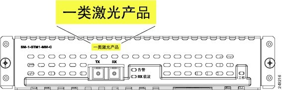
Warning ![]() Class 1 LED product. Statement 1027.
Class 1 LED product. Statement 1027.
Warning ![]() Invisible laser radiation may be emitted from the end of the unterminated fiber cable or connector. Do not view directly with optical instruments. Viewing the laser output with certain optical instruments (for example, eye loupes, magnifiers, and microscopes) within a distance of 100 mm may pose an eye hazard. Statement 1056
Invisible laser radiation may be emitted from the end of the unterminated fiber cable or connector. Do not view directly with optical instruments. Viewing the laser output with certain optical instruments (for example, eye loupes, magnifiers, and microscopes) within a distance of 100 mm may pose an eye hazard. Statement 1056
FCC Class A Compliance
This equipment has been tested and found to comply with the limits for a Class A digital device, pursuant to part 15 of the FCC rules. These limits are designed to provide reasonable protection against harmful interference when the equipment is operated in a commercial environment. This equipment generates, uses, and radiates radio-frequency energy and, if not installed and used in accordance with the instruction manual, may cause harmful interference to radio communications. Operation of this equipment in a residential area is likely to cause harmful interference, in which case users are required to correct the interference at their own expense.
You can determine whether your equipment is causing interference by turning it off. If the interference stops, it was probably caused by the Cisco equipment or one of its peripheral devices. If the equipment causes interference to radio or television reception, try to correct the interference by using one or more of the following measures:
•![]() Turn the television or radio antenna until the interference stops.
Turn the television or radio antenna until the interference stops.
•![]() Move the equipment to one side of the television or radio.
Move the equipment to one side of the television or radio.
•![]() Move the equipment farther away from the television or radio.
Move the equipment farther away from the television or radio.
•![]() Plug the equipment into an outlet that is on a different circuit from the television or radio. (That is, make certain the equipment and the television or radio are on circuits controlled by different circuit breakers or fuses.)
Plug the equipment into an outlet that is on a different circuit from the television or radio. (That is, make certain the equipment and the television or radio are on circuits controlled by different circuit breakers or fuses.)
 Feedback