
 Feedback
Table Of Contents
Installing a Standard Power Supply
Installing a Redundant Power Supply
Configuring the Redundant Power Supply
Cisco IOS Configuration Instructions
Status of Redundant Power Supply
Replacing the Power Supply
This appendix contains information on how to replace the power supply for the access server field-replaceable units. The appendix contains the following sections:
•
Removing the Old Power Supply
•
•
•
Safety Recommendations
Note the following safety recommendations:
Warning

Warning ![]()
Warning ![]()
Warning ![]()
Warning ![]()
Warning ![]()

Required Tools and Equipment
You need the following tools and equipment:
•![]() Medium-size Phillips screwdriver
Medium-size Phillips screwdriver
•![]() ESD-preventive wrist strap
ESD-preventive wrist strap
•![]() Tie-wraps (optional)
Tie-wraps (optional)
•![]() Antistatic bag (optional)
Antistatic bag (optional)
Removing the Chassis Cover
You must open the access server chassis to gain access to its interior components: boot read-only memory (ROM) software, dynamic random-access memory (DRAM) SIMMs, and Flash memory SIMMs. (When you replace the boot ROMs, you must also remove all feature cards in the chassis.)
Take these steps:
Step 1 ![]() Turn the power switch on the access server OFF and disconnect site power. (Note that the power switch is part of the power supply.)
Turn the power switch on the access server OFF and disconnect site power. (Note that the power switch is part of the power supply.)
Step 2 ![]() If using a DC-powered unit, refer to and complete steps a to d.
If using a DC-powered unit, refer to and complete steps a to d.
Warning ![]()
Before performing any of the following procedures, ensure that power is removed from the DC circuit. To ensure that all power is OFF, locate the circuit breaker on the panel board that services the DC circuit, switch the circuit breaker to the OFF position, and tape the switch handle of the circuit breaker in the OFF position.
Figure C-1 DC Power Supply Connections

(a) ![]() Loosen the three locking screws for the negative, positive, and ground connectors on the DC power supply terminal block.
Loosen the three locking screws for the negative, positive, and ground connectors on the DC power supply terminal block.
(b) ![]() Remove the -48 VDC wire from the terminal block negative connector (-).
Remove the -48 VDC wire from the terminal block negative connector (-).
(c) ![]() Remove the +48 VDC wire from the terminal block positive connector (+).
Remove the +48 VDC wire from the terminal block positive connector (+).
(d) ![]() Remove the safety ground (green wire) from the terminal block ground connector.
Remove the safety ground (green wire) from the terminal block ground connector.
Step 3 ![]() Remove all interface cables from the rear panel of the access server.
Remove all interface cables from the rear panel of the access server.
Step 4 ![]() Place the access server so that the front panel is facing you.
Place the access server so that the front panel is facing you.
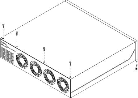
Step 5 ![]() Remove the four screws on the chassis cover, as shown in .
Remove the four screws on the chassis cover, as shown in .
Figure C-2 Removing the Chassis Cover Screws
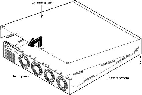
Step 6 ![]() Lift the chassis cover upward, as shown in , and pull it away from the tabs on the rear of the chassis.
Lift the chassis cover upward, as shown in , and pull it away from the tabs on the rear of the chassis.
Figure C-3 Removing the Chassis Cover
Step 7 ![]() Continue with the following section, "Removing the Old Power Supply."
Continue with the following section, "Removing the Old Power Supply."
Removing the Old Power Supply
This section describes how to remove the power supply. Note the following safety warnings before you remove the power supply:
Warning ![]()
Ultimate disposal of this product should be handled according to all national laws and regulations.
Warning ![]()
Only trained and qualified personnel should be allowed to install or replace this equipment.
Warning ![]()
Read the installation instructions before you connect the system to its power source.
Warning ![]()
Before working on a system that has an on/off switch, turn OFF the power and unplug the power cord.
Warning ![]()
Before working on equipment that is connected to power lines, remove jewelry (including rings, necklaces, and watches). Metal objects will heat up when connected to power and ground and can cause serious burns or weld the metal object to the terminals.
To remove the power supply:
Step 1 ![]() Place the access server so that the rear panel is facing you.
Place the access server so that the rear panel is facing you.
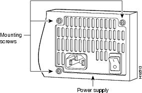
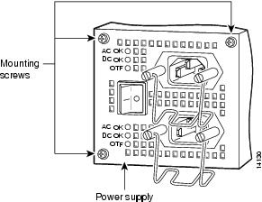
Step 2 ![]() Remove the three mounting screws that secure the power supply to the chassis and set them aside. (See .)
Remove the three mounting screws that secure the power supply to the chassis and set them aside. (See .)

Note ![]() Figure C-4 shows only a single-plug power supply, however you can also remove a redundant power supply in this step.
Figure C-4 shows only a single-plug power supply, however you can also remove a redundant power supply in this step.
Figure C-4 Removing the Power Supply Mounting Screws
Step 3 ![]() Turn the access server so that the front panel is facing you.
Turn the access server so that the front panel is facing you.
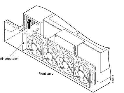
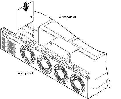
Step 4 ![]() Lift the air separator out of the chassis. (See .)
Lift the air separator out of the chassis. (See .)
Figure C-5 Removing the Air Separator
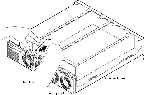
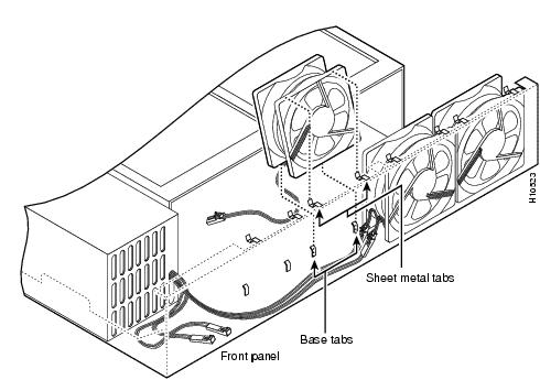
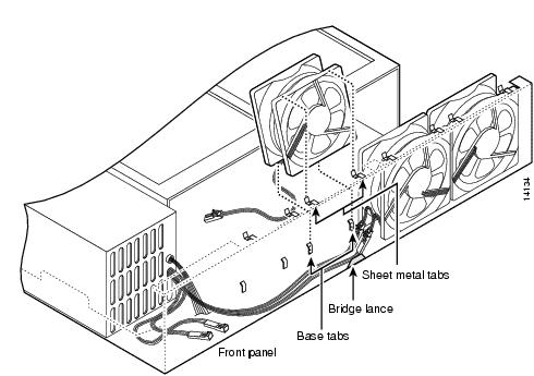
Step 5 ![]() Pull the fan closest to the power supply away from the sheet metal tabs. (See .)
Pull the fan closest to the power supply away from the sheet metal tabs. (See .)
Figure C-6 Pulling the Fan Away from the Tabs
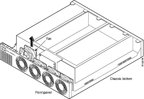
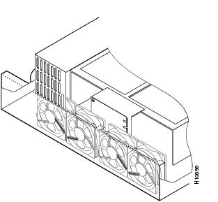
Step 6 ![]() Lift the fan out of the chassis as shown in , and set the fan on top of the power supply.
Lift the fan out of the chassis as shown in , and set the fan on top of the power supply.
Figure C-7 Removing the Fan
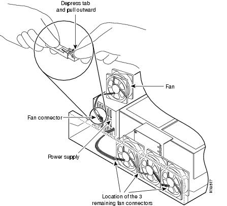
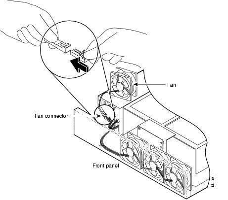
Step 7 ![]() Depress the tab as shown in Figure C-8.
Depress the tab as shown in Figure C-8.
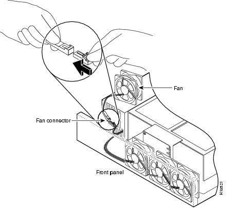
Step 8 ![]() Disconnect the fan cable as shown in , and set aside the fan.
Disconnect the fan cable as shown in , and set aside the fan.
Figure C-8 Disconnecting the Fan Cable
Step 9 ![]() Remove the next fan and disconnect its cable.
Remove the next fan and disconnect its cable.
Step 10 ![]() Remove the cables for the two remaining fans. You can disconnect these cables without removing the fans.
Remove the cables for the two remaining fans. You can disconnect these cables without removing the fans.
Note ![]() There are three different lengths of 2 wire ± 12 VDC power cables. The two shortest cables go to the two fans that you removed in Step 6 through Step 8. The two longer cables go to the two remaining fans removed in Step 9 and this step. The remaining cable goes to the power connector on the backplane.
There are three different lengths of 2 wire ± 12 VDC power cables. The two shortest cables go to the two fans that you removed in Step 6 through Step 8. The two longer cables go to the two remaining fans removed in Step 9 and this step. The remaining cable goes to the power connector on the backplane.
These cables are color-coded. If you use an incorrect cable to connect a fan or the backplane, then you will be unable to make one of the other connections. To help with reconnecting the cables, write down which colored cable and the fan to which it connects.
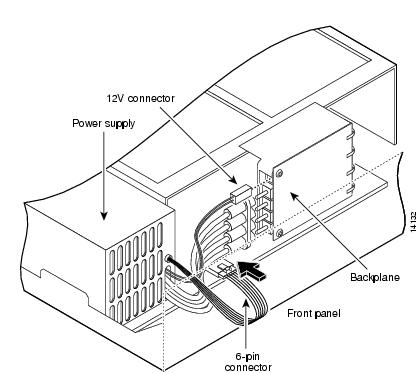
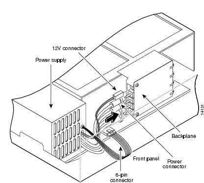
Step 11 ![]() Disconnect the power connectors from the backplane as shown in . First disconnect the 2-pin 12V connector, then disconnect the power connector's 4-jack harness.
Disconnect the power connectors from the backplane as shown in . First disconnect the 2-pin 12V connector, then disconnect the power connector's 4-jack harness.
Figure C-9 Disconnecting the Power Connectors from the Backplane
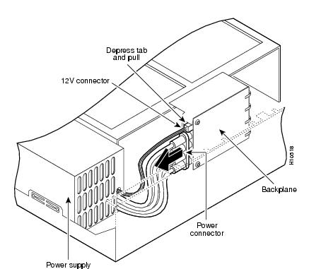
Note ![]() If you are replacing a redundant power supply, disconnect the 6-pin connector from the motherboard before going to Step 12.
If you are replacing a redundant power supply, disconnect the 6-pin connector from the motherboard before going to Step 12.
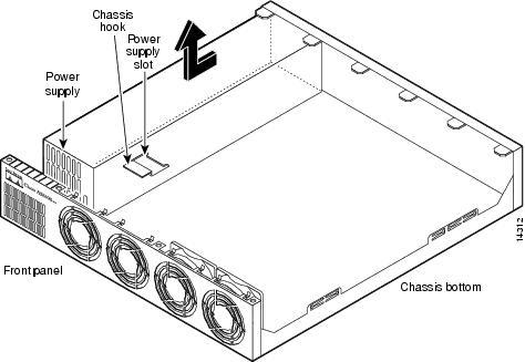
Step 12 ![]() Slide the power supply toward the front panel to disengage the power supply hook from the chassis hook, as shown in . Then remove the power supply from the chassis.
Slide the power supply toward the front panel to disengage the power supply hook from the chassis hook, as shown in . Then remove the power supply from the chassis.
Figure C-10 Lifting the Power Supply Out of the Chassis
Warning ![]()
Ultimate disposal of this product should be handled according to all national laws and regulations.
Step 13 ![]() Continue with one of the following sections:
Continue with one of the following sections:
•![]() Installing a Standard Power Supply
Installing a Standard Power Supply
•![]() Installing a Redundant Power Supply
Installing a Redundant Power Supply
Installing a Standard Power Supply
Take these steps:
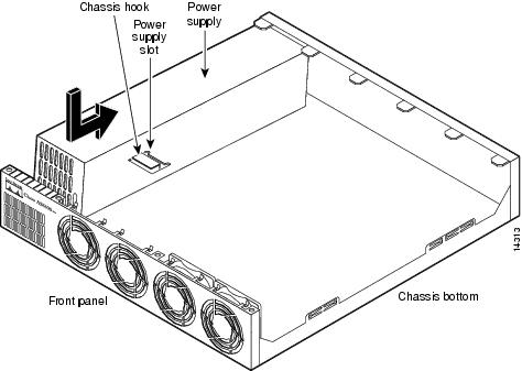
Step 1 ![]() Place the power supply as shown in , and then slide it toward the rear panel. You will be able to feel the hooks engage.
Place the power supply as shown in , and then slide it toward the rear panel. You will be able to feel the hooks engage.
Figure C-11 Inserting the Power Supply in the Chassis
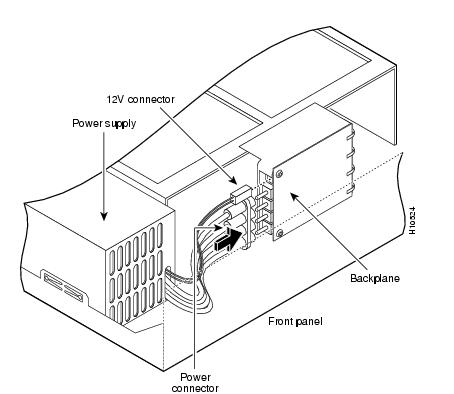
Step 2 ![]() First reconnect the 4-jack harness and then reconnect the 2-pin 12V connector, as shown in . Note that, for clarity, the illustration does not show the fans in place.
First reconnect the 4-jack harness and then reconnect the 2-pin 12V connector, as shown in . Note that, for clarity, the illustration does not show the fans in place.
Figure C-12 Reconnecting the Power Cables to the Backplane
Step 3 ![]() Route the fan cables exactly as shown in . Note that the two longest cables are connected to the two installed fans on the right. The connectors to these two fans will fit into the space between the second and third fans.
Route the fan cables exactly as shown in . Note that the two longest cables are connected to the two installed fans on the right. The connectors to these two fans will fit into the space between the second and third fans.
Figure C-13 Routing the Fan Cables
Step 4 ![]() Insert the middle fan as shown in , making sure that the cable feeds to your left. Position the cables to the two installed fans so that they will fit under the first and second fans. Press the fan into place between the four sheet metal tabs.
Insert the middle fan as shown in , making sure that the cable feeds to your left. Position the cables to the two installed fans so that they will fit under the first and second fans. Press the fan into place between the four sheet metal tabs.
Step 5 ![]() Reconnect the two 2-pin fan cables as shown in .
Reconnect the two 2-pin fan cables as shown in .
Figure C-14 Reconnecting the Fan Cables
Step 6 ![]() Reinstall the remaining fan. Make sure you orient the fan so that the cables feed to the right (toward the second fan). Then route the cable completely under the fan before you reconnect it. This takes up the extra length of fan cable and keeps it out of the way.
Reinstall the remaining fan. Make sure you orient the fan so that the cables feed to the right (toward the second fan). Then route the cable completely under the fan before you reconnect it. This takes up the extra length of fan cable and keeps it out of the way.
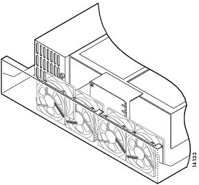
When correctly assembled, the cables appear as shown in .
Figure C-15 Correct Fan Cable Routing
Step 7 ![]() Replace the air separator as shown in , holding all cables to the right of the separator as you slip it into the chassis.
Replace the air separator as shown in , holding all cables to the right of the separator as you slip it into the chassis.
Figure C-16 Replacing the Air Separator
Step 8 ![]() Turn the access server so that you face the rear panel, and then reinstall the three mounting screws as shown in .
Turn the access server so that you face the rear panel, and then reinstall the three mounting screws as shown in .
Figure C-17 Replacing the Power Supply Mounting Screws
Step 9 ![]() If you installed a different type of power supply (AC or DC) than was originally installed in the access server, place one of the power ratings labels that arrived in the plastic bag with the documentation directly over the power ratings information on the rear panel. For example, if the original chassis came with an AC power supply and you replaced it with a DC power supply, place the DC power ratings label over the ratings stamped on the rear panel of the chassis. This will ensure that the correct power ratings information appears on the rear panel.
If you installed a different type of power supply (AC or DC) than was originally installed in the access server, place one of the power ratings labels that arrived in the plastic bag with the documentation directly over the power ratings information on the rear panel. For example, if the original chassis came with an AC power supply and you replaced it with a DC power supply, place the DC power ratings label over the ratings stamped on the rear panel of the chassis. This will ensure that the correct power ratings information appears on the rear panel.
Step 10 ![]() Replace the chassis cover as described in the section, "Replacing the Chassis Cover," later in this appendix.
Replace the chassis cover as described in the section, "Replacing the Chassis Cover," later in this appendix.
Installing a Redundant Power Supply
A redundant power supply has two power cords to provide higher reliability and load balancing. Use the redundant power supply to:
•![]() Manage your system with alarms and other management features.
Manage your system with alarms and other management features.
•![]() Provide a higher reliability with a second built-in power supply.
Provide a higher reliability with a second built-in power supply.
•![]() Balance loads.
Balance loads.
Note ![]() If your motherboard does not support a redundant power supply, the power supply will balance loads, but cannot be managed by your system with alarms and other management features. See the "Configuring the Redundant Power Supply" section for more details.
If your motherboard does not support a redundant power supply, the power supply will balance loads, but cannot be managed by your system with alarms and other management features. See the "Configuring the Redundant Power Supply" section for more details.
To install the redundant power supply:
Step 1 ![]() Place the redundant power supply as shown in , then slide it toward the rear panel. You will be able to feel the chassis hook engage with the slot on the bottom of the power supply.
Place the redundant power supply as shown in , then slide it toward the rear panel. You will be able to feel the chassis hook engage with the slot on the bottom of the power supply.
Figure C-18 Inserting the Redundant Power Supply in the Chassis
Step 2 ![]() Connect the 6-pin connector to the motherboard, as shown in . Note that, for clarity, the illustration does not show the fans in place or the fan cables.
Connect the 6-pin connector to the motherboard, as shown in . Note that, for clarity, the illustration does not show the fans in place or the fan cables.
Note ![]() If you have a motherboard that does not support a redundant power supply with the 6-pin connection, secure the loose 6-pin connector so that it will not interfere with the fans or other moving parts, then go to the next step.
If you have a motherboard that does not support a redundant power supply with the 6-pin connection, secure the loose 6-pin connector so that it will not interfere with the fans or other moving parts, then go to the next step.
Figure C-19 Connecting the 6-Pin Connector to the Motherboard
Step 3 ![]() Reconnect the power connector's 4-jack harness, then reconnect the 2-pin 12V connector, as shown in .
Reconnect the power connector's 4-jack harness, then reconnect the 2-pin 12V connector, as shown in .
Figure C-20 Reconnecting the Power Cables to the Backplane
Step 4 ![]() Route the fan cables exactly as shown in . Note that the two longest cables are connected to the two installed fans on the right. The connectors to these two fans will fit into the space between the second and third fans.
Route the fan cables exactly as shown in . Note that the two longest cables are connected to the two installed fans on the right. The connectors to these two fans will fit into the space between the second and third fans.
Figure C-21 Routing the Fan Cables
Step 5 ![]() Insert the second fan as shown in , making sure that the fan cable feeds to your left. Position the cables to the two installed fans so that they will fit under the first and second fans. Press the fan into place between the four sheet metal tabs.
Insert the second fan as shown in , making sure that the fan cable feeds to your left. Position the cables to the two installed fans so that they will fit under the first and second fans. Press the fan into place between the four sheet metal tabs.
Step 6 ![]() Reconnect the two 2-pin fan cables to the remaining fan, as shown in .
Reconnect the two 2-pin fan cables to the remaining fan, as shown in .
Figure C-22 Reconnecting the Fan Cables
Step 7 ![]() Reinstall the remaining fan. Make sure you orient the fan so that the cables feed to the right (toward the second fan). Then route the cable completely under the fan before you reconnect it. This takes up the extra length of fan cable and keeps it out of the way.
Reinstall the remaining fan. Make sure you orient the fan so that the cables feed to the right (toward the second fan). Then route the cable completely under the fan before you reconnect it. This takes up the extra length of fan cable and keeps it out of the way.
When correctly assembled, the cables appear as shown in .
Figure C-23 Correct Fan Cable Routing
Step 8 ![]() Replace the air separator as shown in , holding all cables to the right of the separator as you slip it into the chassis.
Replace the air separator as shown in , holding all cables to the right of the separator as you slip it into the chassis.
Figure C-24 Replacing the Air Separator
Step 9 ![]() Turn the access server so that you face the rear panel, and then reinstall the three mounting screws as shown in .
Turn the access server so that you face the rear panel, and then reinstall the three mounting screws as shown in .
Figure C-25 Replacing the Redundant Power Supply Mounting Screws
Step 10 ![]() Replace the chassis cover using the procedures in the following section, "Replacing the Chassis Cover," and then configure your redundant power supply using the procedures in the section, "Configuring the Redundant Power Supply."
Replace the chassis cover using the procedures in the following section, "Replacing the Chassis Cover," and then configure your redundant power supply using the procedures in the section, "Configuring the Redundant Power Supply."
Replacing the Chassis Cover
To replace the chassis cover, take these steps:
Step 1 ![]() Place the chassis bottom so that the front panel is facing you.
Place the chassis bottom so that the front panel is facing you.
Step 2 ![]() Hold the chassis cover over the chassis bottom, and align each of the cover tabs with the chassis tabs at the top rear of the chassis, as shown in Figure C-26.
Hold the chassis cover over the chassis bottom, and align each of the cover tabs with the chassis tabs at the top rear of the chassis, as shown in Figure C-26.
Figure C-26 Replacing the Chassis Cover
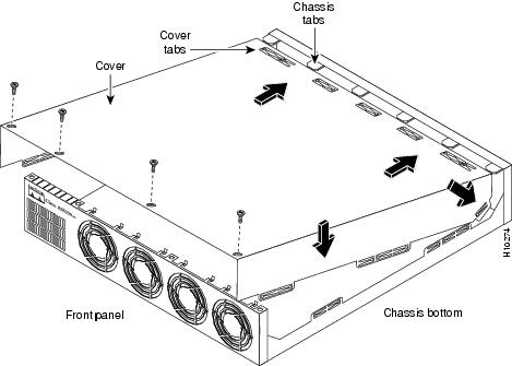
Step 3 ![]() Lower the front of the top cover to close the chassis, and ensure the following:
Lower the front of the top cover to close the chassis, and ensure the following:
•![]() The chassis cover tabs fit under the edge of the chassis rear panel so that they are not exposed.
The chassis cover tabs fit under the edge of the chassis rear panel so that they are not exposed.
•![]() The chassis tabs fit under the chassis cover so that they are not exposed.
The chassis tabs fit under the chassis cover so that they are not exposed.
•![]() The chassis cover side tabs on both sides fit inside the chassis side panels so that they are not exposed.
The chassis cover side tabs on both sides fit inside the chassis side panels so that they are not exposed.
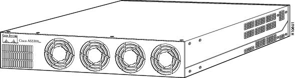
When the chassis cover is properly assembled, no tabs are visible, as shown in .
Figure C-27 Cisco AS5300 Chassis
Step 4 ![]() Secure the chassis cover with four screws.
Secure the chassis cover with four screws.
Step 5 ![]() Reinstall the chassis on a rack, desktop, or table.
Reinstall the chassis on a rack, desktop, or table.
Step 6 ![]() Reinstall all interface cables.
Reinstall all interface cables.
Step 7 ![]() Reconnect the AC power cord. Or, if using a DC-powered unit, refer to , and then complete steps a to d.
Reconnect the AC power cord. Or, if using a DC-powered unit, refer to , and then complete steps a to d.
Warning ![]()
The illustration shows the DC power supply terminal block. Wire the DC power supply using the appropriate wire terminations at the wiring end, as illustrated. The proper wiring sequence is ground to ground, positive to positive, and negative to negative. Note that the ground wire should always be connected first and disconnected last.
Figure C-28 DC Power Supply Connections
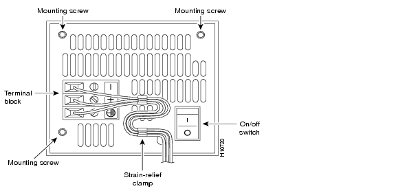
(a) ![]() Insert the safety ground (green wire) into the terminal block ground connector and tighten the locking screw. Ensure that no bare wire is exposed.
Insert the safety ground (green wire) into the terminal block ground connector and tighten the locking screw. Ensure that no bare wire is exposed.
(b) ![]() Insert the +48 VDC wire into the terminal block positive connector (+) and tighten the locking screw. Ensure that no bare wire is exposed.
Insert the +48 VDC wire into the terminal block positive connector (+) and tighten the locking screw. Ensure that no bare wire is exposed.
(c) ![]() Insert the -48 VDC wire into the terminal block negative connector (-) and tighten the locking screw. Ensure that no bare wire is exposed.
Insert the -48 VDC wire into the terminal block negative connector (-) and tighten the locking screw. Ensure that no bare wire is exposed.
(d) ![]() Make sure the power supply cord is secured to the cable strain-relief clamps on the DC power supply with cable ties.
Make sure the power supply cord is secured to the cable strain-relief clamps on the DC power supply with cable ties.
Warning ![]()
After wiring the DC power supply, remove the tape from the circuit breaker switch handle and reinstate power by moving the handle of the circuit breaker to the ON position.
Note ![]() If you are using a redundant power supply, you can order a Y-connector (CAB-AC-Y) to plug into both power connectors in the power supply. If you use this Y-connector, you remove the backup feature of this power supply by eliminating redundant operations and reducing reliability. Cisco highly recommends that you use both power cords whenever possible.
If you are using a redundant power supply, you can order a Y-connector (CAB-AC-Y) to plug into both power connectors in the power supply. If you use this Y-connector, you remove the backup feature of this power supply by eliminating redundant operations and reducing reliability. Cisco highly recommends that you use both power cords whenever possible.
Step 8 ![]() Power ON the access server.
Power ON the access server.
The internal power supply fan should power on. If you are using a redundant power supply, the six green LEDs on the front of the power supply should light. If one LED is not lit, consult the appropriate redundant power supply software message to determine where the problem is located.
Step 9 ![]() If you are using a redundant power supply, continue with the following section, "Configuring the Redundant Power Supply."
If you are using a redundant power supply, continue with the following section, "Configuring the Redundant Power Supply."
Configuring the Redundant Power Supply
Cisco IOS Support
The following Cisco IOS releases fully support the redundant power supply, however, you can use the redundant power supply with older releases for load balancing purposes only.
•![]() 12.0 (1) and later
12.0 (1) and later
•![]() 11.3(6)AA and later
11.3(6)AA and later
•![]() 11.3(6)T and later
11.3(6)T and later
Cisco IOS Configuration Instructions
When the Cisco IOS software detects a failure or recovery from the redundant power supply unit, the Cisco IOS software sends an SNMP message to the configured SNMP server. Unlike messages that are sent to the console every minute, only one SNMP message is sent when the failure is first detected and another one is sent when the recovery is detected. Use this section to manage your Cisco AS5300 universal access server to use SNMP traps (messages). If you do not want to implement SNMP traps, skip this section.
Configure
Verify
To verify you have enabled sending SNP traps for Redundant Power Supply events:
•![]() Enter the show running-config command and note that envmon is enabled.
Enter the show running-config command and note that envmon is enabled.
5300# show running-config
Building configuration...
Current configuration:
!
version 12.0
service timestamps debug uptime
service timestamps log uptime
no service password-encryption
!
hostname as5300
!
ip subnet-zero
!
!
interface Ethernet0
ip address 1.16.44.23 255.255.255.0
no ip directed-broadcast
!
interface FastEthernet0
no ip address
no ip directed-broadcast
shutdown
!
ip classless
ip route 0.0.0.0 0.0.0.0 Ethernet0
ip route 223.255.254.0 255.255.255.0 Ethernet0
!
snmp-server community public RO
snmp-server enable traps snmp
snmp-server enable traps isdn call-information
snmp-server enable traps config
snmp-server enable traps entity
snmp-server enable traps envmon
snmp-server enable traps bgp
snmp-server enable traps frame-relay
snmp-server enable traps syslog
snmp-server host 172.22.19.7 traps public
!
line con 0
transport input none
line aux 0
line vty 0 4
login
!
end
Tips
If you are having trouble:
•![]() Verify that you installed the redundant power supply unit properly.
Verify that you installed the redundant power supply unit properly.
•![]() Verify that you entered the snmp-server commands (mentioned in the Configure section) properly.
Verify that you entered the snmp-server commands (mentioned in the Configure section) properly.
Status of Redundant Power Supply
To display the current status of the Redundant Power Supply unit (if present):
•![]() Use SNMP to get requests on CISCO-ENVMON-MIB/CISCO-ACCESS-ENVMON-MIB attributes.
Use SNMP to get requests on CISCO-ENVMON-MIB/CISCO-ACCESS-ENVMON-MIB attributes.
•![]() Enter the show environment command.
Enter the show environment command.
5300# show environment
Power Supply:
Redundant Power System is present.
RPS Input Voltage status: normal
RPS Output Voltage status: normal
RPS Fan status: normal
RPS Thermal status: normal
RPS OverVoltage status: normal
Board Temperature:
normal
5300#