
 Feedback
Table Of Contents
Setting the Chassis on a Desktop
Connecting to an Ethernet Network
Connecting the Console Terminal and Modem
Connecting to the Console Port
Connecting a Modem to the Auxiliary Port
Installing the Cisco AS5300
This chapter guides you through the installation of the Cisco AS5300 universal access server and includes the following sections:
•
Connecting the Console Terminal and Modem
Warning
Only trained and qualified personnel should be allowed to install or replace this equipment.
Warning
This equipment is intended to be grounded. Ensure that the host is connected to earth ground during normal use.
Warning
Incorrect connection of this or connected equipment to the general purpose outlet could result in a hazardous situation.
Required Tools and Equipment
The following items are included with the access server:
•
•
•
•
•
•
•
•
•
•
You might need the following equipment, which is not included:
•
•
•
•
•
•
•
Setting Up the Chassis
You can set the chassis on a desktop or install it in a rack. Use the procedure in this section that best meets the needs of your network:
•
Warning
When installing the unit, the ground connection must always be made first and disconnected last.
Warning
This unit is intended for installation in restricted access areas. A restricted access area is where access can only be gained by service personnel through the use of a special tool, lock and key, or other means of security, and is controlled by the authority responsible for the location.
Setting the Chassis on a Desktop
The location of the chassis is extremely important for proper operation. Equipment placed too close together, inadequate ventilation, and inaccessible panels can cause malfunctions and shutdowns, and can make maintenance difficult. The following information will help you to plan the location of the chassis:
•
•
Attach the rubber feet as shown in . Rubber feet are included in the accessory kit that shipped with your access server.
Figure 3-1 Attaching the Rubber Feet
Rack-Mounting the Chassis
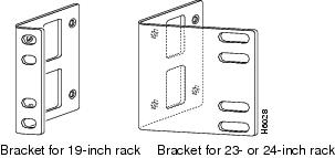
This section describes how to rack-mount the chassis. The access server arrives with 19-inch rack-mount brackets and larger brackets for use with a 23- or 24-inch rack. (See .) You can also order telco rack-mount brackets (see ). The part number for telco brackets is AS52/3RM-TELCO-19"=.
The following information will help you plan your equipment rack configuration:
•
•
•
•
•
Warning
Before working on a chassis or working near power supplies, unplug the power cord on AC units; disconnect the power at the circuit breaker on DC units.
Required Tools and Equipment
You need the following tools and equipment to rack-mount the chassis:
•
•
•
Figure 3-2 Standard Rack-Mount Brackets
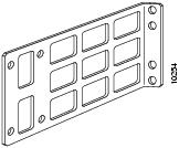
Figure 3-3 Telco Rack-Mount Bracket
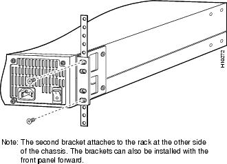
Attaching the Brackets
To install the chassis in a rack, attach the brackets in one of the following ways:
•
•
Note
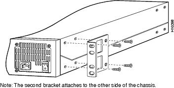
Figure 3-4 Standard Bracket Installation—Front Panel Forward
Figure 3-5 Standard Bracket Installation—Rear Panel Forward
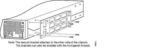
Figure 3-6 Optional Telco Bracket Installation—Rear Panel Forward
Installing in a Rack
After the brackets are secured to the chassis, you can rack-mount the access server. Using the screws that you provide, attach the chassis to the rack as shown in .
Figure 3-7 Attaching the Chassis to the 19-Inch Rack—Rear Panel Forward
Connecting to the Network
This section describes how to connect the access server to your network. The cables required to connect the access server to a network are not provided. For ordering information, contact customer service (see the section "Cisco Connection Online" in the "Preface") or see the appendix "" for cable and port pinouts.
Warning
To avoid electric shock, do not connect safety extra-low voltage (SELV) circuits to telephone-network voltage (TNV) circuits. LAN ports contain SELV circuits, and WAN ports contain TNV circuits. Some LAN and WAN ports use both RJ-45 connectors. Use caution when connecting cables.
Note
Warning


Note ![]() The access server arrives with all cards already installed, unless you order a card separately as a spare. Refer to the Cisco AS5300 Universal Access Server Module Installation Guide for card installation instructions.
The access server arrives with all cards already installed, unless you order a card separately as a spare. Refer to the Cisco AS5300 Universal Access Server Module Installation Guide for card installation instructions.
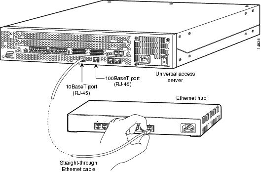
Connecting to an Ethernet Network
You can connect the access server to an Ethernet network by using a straight-through RJ-45-to-RJ-45 Ethernet cable to connect the Ethernet 10BaseT or 10/100BaseT port to an Ethernet hub. (See .)
Figure 3-8 Connecting to an Ethernet Hub (10BaseT Shown)
Connecting to a WAN
You can connect the access server to a WAN in the following ways:
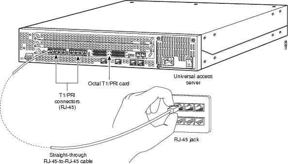
•![]() Use a straight-through RJ-45-to-RJ-45 cable to connect each T1/PRI port to an RJ-45 jack. (See .)
Use a straight-through RJ-45-to-RJ-45 cable to connect each T1/PRI port to an RJ-45 jack. (See .)
•![]() Use an E1 cable to connect each E1/PRI port to an E1 channel service unit (CSU) or data service unit (DSU). (See .)
Use an E1 cable to connect each E1/PRI port to an E1 channel service unit (CSU) or data service unit (DSU). (See .)
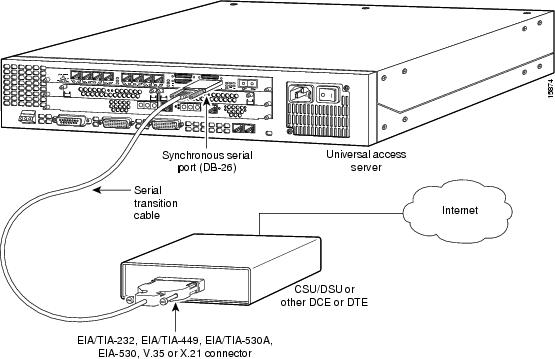
•![]() Use a a serial transition cable to connect one of the four synchronous serial ports to a modem or a CSU/DSU.
Use a a serial transition cable to connect one of the four synchronous serial ports to a modem or a CSU/DSU.

Warning ![]()
Before opening the chassis, disconnect the telephone-network cables to avoid contact with telephone-network voltages.
Warning ![]()
Hazardous network voltages are present in WAN ports regardless of whether power to the router is OFF or ON. To avoid electric shock, use caution when working near WAN ports. When detaching cables, detach the end away from the router first.
Figure 3-9 Connecting to an RJ-45C (T1) Jack
A 10-position rotary switch (labeled IMP SEL) allows you to choose the number of ports that are terminated as 75-ohm unbalanced lines. The LED labeled 120 at each port indicates the input impedance of that port. If the LED is on, it indicates the impedance of the port is set to 120 ohms. If the LED is off, it indicates the impedance of the port is set to 75 ohms.
If you are connecting to a port with 75-ohm input impedance, use an RJ-45-to-75-ohm coaxial cable adapter and plug it into a port with the 120 LED off.
Warning ![]()
This equipment is to be installed and maintained by service personnel only as defined by AS/NZS 3260 Clause 1.2.14.3 Service Personnel.
Warning ![]()
The telecommunications lines must be disconnected 1) before unplugging the main power connector and/or 2) while the housing is open.
Warning ![]()
The E1 interface card may only be installed in an ACA-permitted customer equipment or a Data Terminal Equipment (DTE) that is exempted from ACA's permit requirements. The customer equipment must only be housed in a cabinet that has screw-down lids to stop user access to overvoltages on the customer equipment. The customer equipment has circuitry that may have telecommunications network voltages on them.
Figure 3-10 Connecting to an E1 CSU/DSU

Figure 3-11 Connecting to a CSU/DSU
Connecting the Console Terminal and Modem
Use the console terminal for local administrative access to the access server. You can only connect a terminal to the console port. You can use the auxiliary port to connect a terminal or a modem for remote access to the access server.
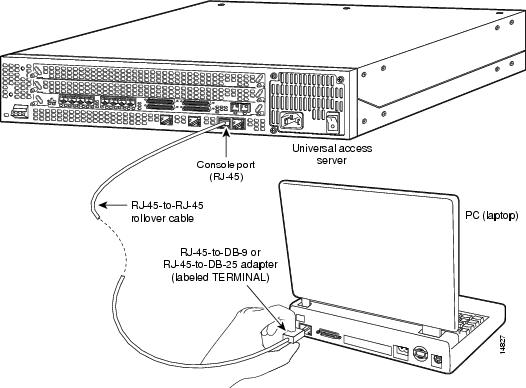
Connecting to the Console Port
To connect a terminal (an ASCII terminal or a PC running terminal emulation software) to the console port on the access server:
Step 1 ![]() Connect the terminal using an RJ-45 rollover cable and an RJ-45-to-DB-25 or RJ-45-to-DB-9 adapter. The adapters provided are labeled TERMINAL. Other types of adapters are not included. (See .)
Connect the terminal using an RJ-45 rollover cable and an RJ-45-to-DB-25 or RJ-45-to-DB-9 adapter. The adapters provided are labeled TERMINAL. Other types of adapters are not included. (See .)
For additional information on rollover cable pinouts, see the appendix "."
Step 2 ![]() Configure your terminal or PC terminal emulation software for 9600 baud, 8 data bits, no parity, and 2 stop bits.
Configure your terminal or PC terminal emulation software for 9600 baud, 8 data bits, no parity, and 2 stop bits.
Figure 3-12 Connecting the Console Terminal
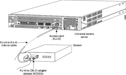
Connecting a Modem to the Auxiliary Port
To connect a modem to the auxiliary port, follow these steps:
Step 1 ![]() Connect a modem to the auxiliary port on the access server using an RJ-45 rollover cable with an RJ-45-to-DB-25 adapter. The adapter provided is labeled MODEM. (See .)
Connect a modem to the auxiliary port on the access server using an RJ-45 rollover cable with an RJ-45-to-DB-25 adapter. The adapter provided is labeled MODEM. (See .)
Step 2 ![]() Make sure that your modem and the auxiliary port on the access server are configured for the same transmission speed (38400 baud is typical) and hardware flow control with Data Carrier Detect (DCD) and Data Terminal Ready (DTR) operations.
Make sure that your modem and the auxiliary port on the access server are configured for the same transmission speed (38400 baud is typical) and hardware flow control with Data Carrier Detect (DCD) and Data Terminal Ready (DTR) operations.
Figure 3-13 Connecting a Modem to the Auxiliary Port
Connecting to the Alarm Port
Do not connect to the three-pin alarm port. The alarm port is disabled. It is a future enhancement that is not supported by current versions of the system software or the feature cards.
Note ![]() Connect the alarm port only to a safety extra-low voltage (SELV) source using 22 AWG, or thicker, copper wire. SELV ratings are maximum 30 Volts AC (RMS), maximum 60 Volts DC, and maximum 50 VA power. The alarm port is rated for 2.0 Amps maximum current.
Connect the alarm port only to a safety extra-low voltage (SELV) source using 22 AWG, or thicker, copper wire. SELV ratings are maximum 30 Volts AC (RMS), maximum 60 Volts DC, and maximum 50 VA power. The alarm port is rated for 2.0 Amps maximum current.
Supplying Power
The access server is available with either an AC or DC power supply. You can also order a power supply as a spare if you decide later that you need a different type of power supply or the power supply fails.
Warning ![]()
Do not touch the power supply when the power cord is connected. For systems with a power switch, line voltages are present within the power supply even when the power switch is off and the power cord is connected. For systems without a power switch, line voltages are present within the power supply when the power cord is connected.
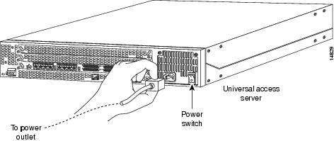
Connecting the AC Power Cord
Take these steps:
Step 1 ![]() Connect one end of the power cord to the power connector on the rear panel of the access server. (See .)
Connect one end of the power cord to the power connector on the rear panel of the access server. (See .)
Step 2 ![]() Connect the other end of the power cord to the power outlet.
Connect the other end of the power cord to the power outlet.
Warning ![]()
The plug-socket combination must be accessible at all times because it serves as the main disconnecting device.
Step 3 ![]() Power ON the access server.
Power ON the access server.
The internal power supply fan should power on.
Figure 3-14 Connecting the AC Power Cord
Wiring the DC Power Supply
If you ordered the access server with a DC power supply, follow the procedure in this section to wire the terminal block.
Warning ![]()
A readily accessible two-poled disconnect device must be incorporated in the fixed wiring.
Warning ![]()
Before performing any of the following procedures, ensure that power is removed from the DC circuit. To ensure that all power is OFF, locate the circuit breaker on the panel board that services the DC circuit, switch the circuit breaker to the OFF position, and tape the switch handle of the circuit breaker in the OFF position.
Note ![]() This product is intended for installation in restricted access areas and is approved for connection using 12 or 14 AWG copper conductors only. The installation must comply with all applicable codes.
This product is intended for installation in restricted access areas and is approved for connection using 12 or 14 AWG copper conductors only. The installation must comply with all applicable codes.
Refer to and follow these steps to wire the terminal block:
Step 1 ![]() Note the orientation of the DC power supply. The power supply cord should have three wires: +48 VDC, -48 VDC, and a safety ground (green wire).
Note the orientation of the DC power supply. The power supply cord should have three wires: +48 VDC, -48 VDC, and a safety ground (green wire).
Note ![]() For central office installations, it is recommended to use a 6 AWG green ground wire with one end connected to reliable earth. The other end of the wire should be crimped onto the double-hole lug provided in the installation pack. The lug should be secured to the mating holes on either side of the chassis with the two screws included in the accessory pack.
For central office installations, it is recommended to use a 6 AWG green ground wire with one end connected to reliable earth. The other end of the wire should be crimped onto the double-hole lug provided in the installation pack. The lug should be secured to the mating holes on either side of the chassis with the two screws included in the accessory pack.
Warning ![]()
Step 2 ![]() Strip off a quarter of an inch (1/4 in. [0.625 cm]) of insulation on the safety ground, +48 VDC, and -48 VDC input wires.
Strip off a quarter of an inch (1/4 in. [0.625 cm]) of insulation on the safety ground, +48 VDC, and -48 VDC input wires.
Step 3 ![]() Install the safety ground (green wire) into the terminal block ground connector and tighten the locking screw. Ensure that no bare wire is exposed.
Install the safety ground (green wire) into the terminal block ground connector and tighten the locking screw. Ensure that no bare wire is exposed.
Step 4 ![]() Insert the +48 VDC wire into the terminal block positive connector (+) and tighten the locking screw. Ensure that no bare wire is exposed.
Insert the +48 VDC wire into the terminal block positive connector (+) and tighten the locking screw. Ensure that no bare wire is exposed.
Step 5 ![]() Insert the -48 VDC wire into the terminal block negative connector (-) and tighten the locking screw. Ensure that no bare wire is exposed.
Insert the -48 VDC wire into the terminal block negative connector (-) and tighten the locking screw. Ensure that no bare wire is exposed.
Step 6 ![]() Secure the power supply cord to the cable strain-relief clamps on the DC power supply with cable ties.
Secure the power supply cord to the cable strain-relief clamps on the DC power supply with cable ties.
Warning ![]()
After wiring the DC power supply, remove the tape from the circuit breaker switch handle and reinstate power by moving the handle of the circuit breaker to the ON position.
Step 7 ![]() Power ON the access server.
Power ON the access server.
The internal power supply fan should power on.
Figure 3-15 DC Power Supply Connections

Where to Go Next
When you power ON the access server for the first time, messages will begin to appear on your console screen. Proceed to the Cisco AS5300 Universal Access Server Software Configuration Guide for configuration instructions. The remainder of this guide includes reference material for replacing spare parts, troubleshooting, and creating your own cables.