Feedback
Table Of Contents
Quad Cards Without Serial Interfaces
Quad Cards With Serial Interfaces
12-Port Microcom Modem Modules
Overview
This chapter provides an overview of the Cisco AS5300 universal access server, a versatile data communications platform that provides the functions of an access server, router, and digital modems in a single modular chassis. The access server is intended for Internet service providers (ISPs), telecommunications carriers, and other service providers that offer managed Internet connections, and also medium to large sites that provide both digital and analog access to users on an enterprise network.
By terminating both analog and digital calls on the same chassis simultaneously, the access server provides you with a clear, simple, and easy migration path from today's analog dial access services to tomorrow's digital dial access services.
This chapter includes the following sections:
Chassis Components
The chassis consists of the following components:
•
One 19-inch modular chassis with a high-speed backplane and three slots for a variety of cards
•
•
•
•
•
•
•
•
•
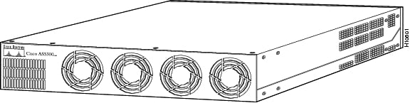
Figure 1-1 Cisco AS5300 Front Panel
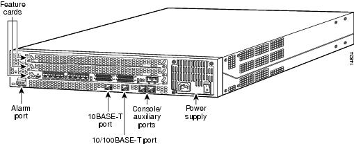
Figure 1-2 Cisco AS5300 Rear Panel
Cards
The chassis includes three card slots (see ) in which you can install a combination of cards.
In any single slot you can install your choice of:
•
•
In the remaining two slots you can install your choice of:
•
•
Note
Note
shows the memory required for the available cards.
Table 1-1 Memory Requirements for Cards
Octal T1/PRI or E1/PRI
DMM
64 MB (upgrade included)
Quad T1/PRI or E1/PRI with serial ports
HMM
32 Meg
Quad T1/PRI or E1/PRI without serial ports
HMM
32 Meg
Quad T1/PRI and E1/PRI Cards
You can install one of two types of Quad cards in any unpopulated slot of the access server chassis:
•
•
Both types of cards are described in the following sections.
Quad Cards Without Serial Interfaces
Quad T1/PRI Card
The Quad T1/PRI card (see ) without serial interfaces includes four RJ-45 ports. Cables are not included with the card; however, port pinouts are listed in the the Cisco AS5300 Module Installation Guide publication. Note that these boards support both MICA and Microcom modems.
A 10-position rotary switch allows the user to choose which of the four ports is selected for monitoring through the Bantam jacks (TXMON, TXIN, TXOUT and RXMON, RXIN, RXOUT). The LED labeled MON at each port lights to indicate that port has been selected for monitoring. Only one port can be selected at a time. None of the ports is selected when the switch is set to the OFF position.
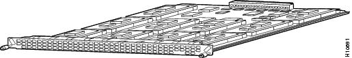
Figure 1-3 Quad T1/PRI Card Without Serial Interfaces
Cables are not included with the card. However, cable specifications and port pinouts are listed in the appendix, "."
Quad E1/PRI Card
The Quad E1/PRI WAN card (see ) without serial interfaces includes four RJ-45 ports for terminating 120-ohm balanced lines or 75-ohm unbalanced lines. Cables are not included with the card. However, cable specifications and port pinouts are listed in the appendix "." Note that these boards support both MICA and Microcom modems.
A 10-position rotary switch allows the user to choose the number of ports that are terminated as 75-ohm unbalanced lines. If the LED labeled 120 at each port is on, it indicates the input impedance of that port is set to 120 ohms. If it is off, the impedance is set to 75 ohms.
Jumper settings on the card can be used to configure the 75-ohm unbalanced ports so the receive shield is connected to ground. Impedance selection switch settings and receive shield jumper positions are described in the next chapter, "Preparing to Install."
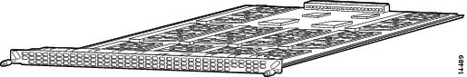
Figure 1-4 Quad E1/PRI Card Without Serial Interfaces
Cables are not included with the card. However, cable specifications and port pinouts are listed in the appendix, "."
Quad Cards With Serial Interfaces
This section describes the Quad T1/PRI and Quad E1/PRI cards () with serial interfaces. Note that these cards do not support Microcom modems.
Note
Figure 1-5 Quad T1/PRI or E1/PRI Card With Serial Interfaces
The board provides 4 RJ-45 T1 or E1 PRI ports and 4 serial interfaces for backhaul WAN support.
The T1/PRI ports are configured as 100-ohm per port. For the Quad E1/PRI WAN card, the four ports can be configured as 75- or 120-ohm lines. The factory-set default is 120-ohm. Note that for the E1/PRI card you change the impedence using a software command. See the chapter "T1/PRI and E1/PRI Cards" in the Cisco AS5300 Universal Access Module Installation Guide for details.
Cables are not included with the card. However, cable specifications and port pinouts are listed in the appendix, "."
Octal T1/PRI and E1/PRI Cards
You can install an Octal E1/PRI or T1/PRI card () in any slot of the access server chassis. The board provides 8 RJ-45 T1 or E1 PRI ports and 4 serial interfaces for backhaul WAN support. Note that these cards do not support Microcom modems.
Note
Figure 1-6 Octal T1/PRI or E1/PRI Card
The T1/PRI ports are configured as 100-ohm per port. For the Octal E1/PRI WAN card, the eight ports can be configured as 75- or 120-ohm lines. The factory-set default is 120-ohm. Note that, unlike the Quad E1/PRI card, the Octal E1/PRI card does not include a rotary switch to choose the input impedence for the ports; you change the impedence using a software command. See the chapter "T1/PRI and E1/PRI Cards" in the Cisco AS5300 Universal Access Module Installation Guide for details.
Cables are not included with the card. However, cable specifications and port pinouts are listed in the appendix, "."
MICA Cards
You can install up to two MICA cards in any unpopulated slot of the access server chassis.
Figure 1-7 MICA Card
Each MICA card includes 10 slots in which you can install 6- or 12-port modem modules.
6-Port Module Cards
Each 6-port module includes 6 modems. Therefore, in a fully populated MICA card, you can have up to 60 modems. Or, in a fully populated access server chassis, you can have up to 120 modems. Ten of these modem modules can be configured on each of two cards for a total of 60 ports per card or a total of 120 ports per chassis.
The 6-port modules cannot be used as standalone cards and they cannot be installed in Microcom cards.
Figure 1-8 MICA Card with 6-Port Modem Modules
12-Port Module Cards
Each 12-port module includes 12 modems. Therefore, in a fully populated MICA card, you can have up to 120 ports. Or, in a fully populated access server chassis, you can have up to 120 modems. Ten of these modem modules can be configured on each of two cards for a total of 120 ports per card or a total of 240 ports per chassis.
The 12-port modules cannot be used as standalone cards and they cannot be installed in Microcom cards.
Figure 1-9 MICA Card with 12-Port Modem Modules
Microcom Card
You can install up to two Microcom cards (see ) in any two slots of the access server chassis. Each Microcom card includes two slots in which you can install any combination of 12-port modem modules, as described below.
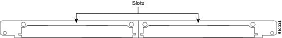
Figure 1-10 Microcom Card
The modules connect through the Microcom carrier card and the system backplane to a Quad or Octal T1/PRI or E1/PRI card installed in the access server chassis. Data is transmitted or received on T1 or E1 lines connected to the Quad or Octal T1/PRI or E1/PRI card and then routed to the 12-port modules installed in the Microcom carrier card.
12-Port Microcom Modem Modules
The chassis supports any combination of the following 12-port modules:
•
•
Note
The 12-port modem modules are not included unless specified in your order. You can order the modem modules separately. Refer to the appendix "Troubleshooting" for ordering information.You must install the 12-port modules in the Microcom card. The 12-port modules cannot be used as standalone cards and they cannot be installed in MICA cards.
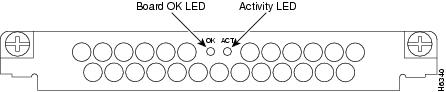
Figure 1-11 V.34 12-Port Modem Module
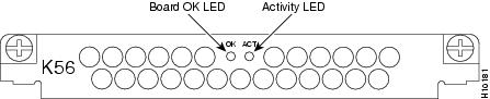
Figure 1-12 56K 12-Port Modem Module
Voice-over-IP (VoIP) Card
The VoIP card is a coprocessing card and software package that adds VoIP capabilities. The VoIP capability enables a Cisco router to carry live voice traffic (for example, telephone calls and faxes) over an IP network. The VoIP card is available as a spare or a factory-intalled card within the chassis.
The VoIP card contains multiple digital signal processor (DSP) modules. It uses the Cisco AS5300's Quad T1/E1 Public Switched Telephone Network (PSTN) interface and local-area network (LAN) or wide-area network (WAN) routing capabilities to provide up to a 48/60 channel gateway for VoIP packetized voice traffic to/from T1/E1 time-division multiplexing (TDM) traffic. Major applications of the VoIP cards include:
•
•
•
•
You can install up to five DSP modules (DSPMs) onto the VoIP card to perform voice processing for up to 30 B channels.
•
•
•
•
•
For a detailed discussion of Voice over IP technology, configuration examples, and commands, see Voice Over IP Software Configuration Guide for the Cisco AS5300.
DSP Modules
The DSP module provides voice compression and packetization services to the VoIP card so that you can configure and expand them.
•
•
•
Power Supply
Either an AC or DC power supply is available. The power supply provides DC power to the installed cards via connectors on the backplane.
The internal power supply is a four-output switching power supply with power factor correction and regulated outputs.
Specifications
Table 1-2 Specifications
Dimensions (H x W x D)
3.5 x 17.5 x 18.25 in. (8.89 x 44.45 x 46.36 cm)
Weight
32 lb maximum (14.5 kg)
Processor
150 MHz
Operating environment
32 to 104×F (0 to 40×C)
Nonoperating temperature
-40 to 185×F (-40 to 85×C)
Operating humidity
5 to 95%, noncondensing
Noise level
70 dB1 @ 3 feet (0.914 m)
Input voltage, AC power supply
Current
Frequency
Power factor
Input AC power100 to 240 VAC2
5 - 2 A
50/60 Hz
0.80 to 0.95
200 to 400W (maximum)Input voltage, DC power supply
Maximum input current
Typical input current
Efficiency
Input DC powerProtection
Output voltage
Output voltage
Output voltage
Output voltage
Peak output power
Maximum system output power
Typical system output power
Ripple and noiseCurrent limit, overpower, overtemperature, (latch off)
3.3 VDC
5.0 VDC
12.0 VDC
-12.0 VDC
350W
300W
250W
under 200 mv at board levelWAN interface options
Quad T1/PRI (RJ-45)
Quad E1/PRI (RJ-45)
Octal T1/PRI (RJ-45)
Octal E1/PRI (RJ-45)
Serial interfaces (for backhaul WAN support)
4 serial line interfaces
LAN interface options
Ethernet 10BaseT (RJ-45)
Ethernet 10/100BaseT selectable (RJ-45)
Console and auxiliary ports
Asynchronous serial (RJ-45)
Regulatory compliance
FCC Part 68. See also the Regulatory Compliance and Safety Information document that shipped with your access server.
1 dB = decibels.
2 VAC = volts alternating current.
3 VDC = volts direct current.
4 W=watts.