Installing Advanced Integration Modules in Cisco 2600 Series, Cisco 3600 Series, and Cisco 3700 Series Routers
Available Languages
Table Of Contents
Preventing Electrostatic Discharge Damage
Installing an AIM in a Cisco Router with a 1-RU Chassis
Removing the Cover from a 1-RU Chassis
Installing the AIM in a 1-RU Chassis
Installing a CompactFlash Memory Card on the AIM
Reinstalling the Cover on a 1-RU Chassis
Installing AIMs in Cisco Routers with Hinged Covers
Removing a Hinged Cover from a Chassis
Installing an AIM in a Chassis with a Hinged Cover
Installing a CompactFlash Memory Card on the AIM
Applying the AIM Label on a Chassis with a Hinged Cover
Reinstalling the Cover on a Chassis with a Hinged Cover
Installing AIMs in a Cisco 3660 Router
Removing the System Board Tray
Installing AIMs in a Cisco 3660 Router
Applying the AIM Label on a Cisco 3660 Router
Reinstalling the System Board Tray
Installing AIMs in a Cisco 3745 Router
Removing the Plug-In System Board from a Cisco 3745 Router
Installing AIMs in a Cisco 3745 Router
Installing a CompactFlash Memory Card on the AIM
Applying the AIM Label on the Cisco 3745 Router
Reinstalling the Plug-In System Board
Configuring Internet Encryption Using Encryption AIMs
Configuring Voice and ATM AIMs
Configuring Data Compression AIMs
Upgrading a PLD on Cisco 2600 Series Routers
Frame Relay Stac Configuration
Obtaining Technical Assistance
Cisco Technical Support Website
Definitions of Service Request Severity
Obtaining Additional Publications and Information
Installing Advanced Integration Modules in Cisco 2600 Series, Cisco 3600 Series, and Cisco 3700 Series Routers
This document describes how to install advanced integration modules (AIMs) in Cisco 2600 series, Cisco 3600 series, and Cisco 3700 series routers.
Use this document in conjunction with the hardware and software configuration guide, and the Cisco 2600 Series, Cisco 3600 Series, and Cisco 3700 Series Regulatory Compliance and Safety Information document, and with the applicable Cisco IOS configuration guides and command references.
If you have questions or need help, see the "Obtaining Documentation" section and the "Obtaining Technical Assistance" section for further information.
This document contains the following sections:
•
Installing an AIM in a Cisco Router with a 1-RU Chassis
•
•
•
•
•
•
•
•
Overview
AIMs provide hardware-based support for various features, depending on the type of AIM installed. AIMs are installed by plugging into internal connectors in the router, and they require no additional external interfaces or connections. See Table 1 for AIM compatibility in Cisco routers.
Each AIM requires Cisco IOS software of a specified or later release, and AIMs typically require Cisco IOS software with a specified Cisco IOS feature set. Consult the relevant specifications, data sheets, or release notes to determine software requirements for an AIM. Cisco IOS software requirement information is also available to registered Cisco.com users from the Software Advisor tool at http://www.cisco.com/cgi-bin/Support/CompNav/Index.pl.
Table 1 AIM Compatibility in Cisco Routers
Voice and ATM
AIM-ATM
AIM-VOICE-30
AIM-ATM-VOICE-30
2600 series with 1-RU chassis,
2600XM series1
1
2691, 3660, 3725, 3745
2
2
Data compression
AIM-COMPR2
2600 series with 1-RU chassis,
2600XM series1
1
AIM-COMPR2-V2
2600XM series
1
1
AIM-COMPR4
2691, 3660, 3725, 3745
2
2
VPN encryption
AIM-VPN/BP
2600 series with 1-RU chassis,
2600XM series, 26911
1
AIM-VPN/BPII
2600XM series
1
1
AIM-VPN/EP
2600 series with 1-RU chassis,
2600XM series1
1
2691, 3725
2
1
AIM-VPN/EPII
2600XM series
1
1
2691
2
1
3631
1
1
3725
2
1
AIM-VPN/HP
AIM-VPN/HPII
3660
2
1
3745
2
1
AIM-VPN/SSL-3
3725, 3745
2
1
Voice mail
AIM-CUE
2600XM series
1
1
2691, 3725
2
1
3745
2
11
1 In AIM slot 1 only. Do not install an AIM-CUE in AIM slot 0 of a Cisco 3745 router.
Software Requirements
Cisco IOS software of a specified release or later release is required to use an AIM.
To determine the version of Cisco IOS software that is running on your router, log in to the router and enter the show version command:
Router> show versionCisco Internetwork Operating System SoftwareIOS (tm) 12.1 Software (c3600-i-mz), Version 12.1(3)XI, RELEASE SOFTWARESafety Recommendations
To ensure general safety, follow these guidelines:
•
•
•
•
•
Notes, Cautions, and Warnings
Notes, cautions, and warnings use the following conventions and symbols:

Note

Caution
Warning Definition

Warning
This warning symbol means danger. You are in a situation that could cause bodily injury. Before you work on any equipment, be aware of the hazards involved with electrical circuitry and be familiar with standard practices for preventing accidents. To see translations of the warnings that appear in this publication, see the translated safety warnings that accompanied this device. Statement 1071
SAVE THESE INSTRUCTIONS
Safety with Electricity
When working on equipment that is powered by electricity, follow these guidelines:
•
•
•
–
–
•
•
•
If an electrical accident occurs, proceed as follows:
•
•
•
•
Preventing Electrostatic Discharge Damage
Electrostatic discharge (ESD) can damage equipment and impair electrical circuitry. ESD can occur when printed circuit cards are improperly handled and can result in complete or intermittent failures. Always follow ESD prevention procedures when removing and replacing cards. Ensure that the router chassis is electrically connected to earth ground. Wear an ESD-preventive wrist strap, ensuring that it makes good skin contact. Connect the clip to an unpainted surface of the chassis frame to safely channel unwanted ESD voltages to ground. To guard against ESD damage and shocks, the wrist strap and cord must be used properly. If no wrist strap is available, ground yourself by touching the metal part of the chassis.
Caution
Required Tools and Equipment
To install an AIM in a chassis, you need the following tools and equipment:
•
•
•
•
•
•
Installing an AIM in a Cisco Router with a 1-RU Chassis
Note
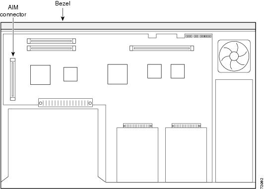
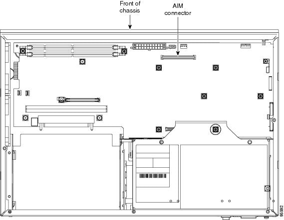
The following sections describe AIM installation in a Cisco router chassis of 1 RU (rack unit) height. AIMs plug into internal AIM connectors located on the system board. (See Figure 1.)
Figure 1 System Board Layout in a 1-RU Chassis
To install an AIM, complete these procedures:
1.
2.
3.
5.
Removing the Cover from a 1-RU Chassis
This section describes how to open the chassis to access internal components.
Warning
Warning
To remove the cover from a Cisco router with a 1-RU chassis, do the following:
Step 1
Step 2
Step 3
Step 4
Step 5
Figure 2 Holding the 1-RU Chassis for Cover Removal
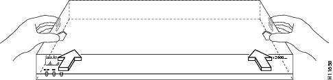
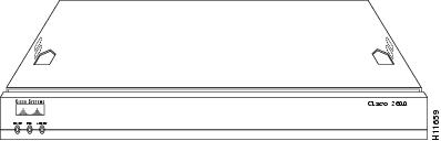
Figure 3 Removing the 1-RU Chassis Cover
Installing the AIM in a 1-RU Chassis
To install an AIM, perform the following procedure. You need a number 2 Phillips screwdriver or flat-blade screwdriver to complete this procedure.
Note
Note
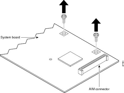
Step 1
Figure 4 Removing the Screws from the System Board in a 1-RU Chassis
Step 2
Caution
Note
Note
Step 3
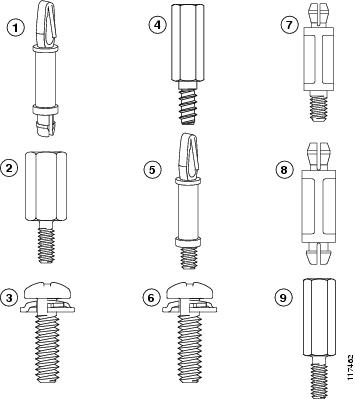
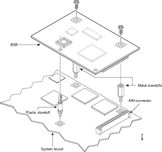
Figure 5 Standoff Orientation
Step 4
Note
Step 5
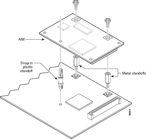
Figure 6 Connecting the AIM to the System Board in a 1-RU Chassis
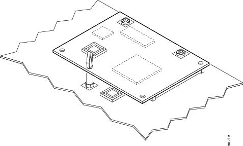
Step 6
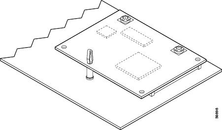
Figure 7 Installed AIM in a 1-RU Chassis
Installing a CompactFlash Memory Card on the AIM
Complete the procedure below for installing a CompactFlash memory card mounted on the AIM. To access the internal CompactFlash memory card, you need to either remove the chassis cover or slide the system board out, depending on the platform. For Cisco 2600XM series and Cisco 2691 routers, see the "Removing the Cover from a 1-RU Chassis" section.
Note
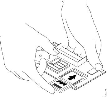
Step 1
Step 2
Step 3
Step 4
Step 5
Figure 8 CompactFlash Memory Card Location on the AIM
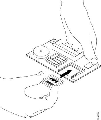
Figure 9 CompactFlash Memory Card Installation on the AIM
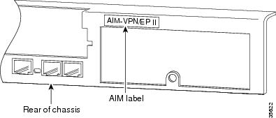
Applying the AIM Label
The AIM label for the chassis might be in the AIM mounting kit, or it might be attached to the label on the AIM card. Apply the chassis label as follows:
Step 1
Step 2
Step 3
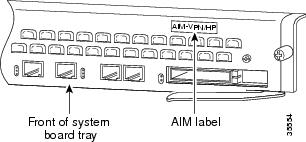
Note
Figure 10 AIM Label Location on 1-RU Chassis
Reinstalling the Cover on a 1-RU Chassis
To reinstall a 1-RU chassis cover, perform the following procedure. To complete this procedure, you need a number 2 Phillips screwdriver or a flat-blade screwdriver.
Step 1
Step 2
•
•
Caution
Step 3
Step 4
Step 5
Step 6
Step 7
Observe the following warning if your Cisco router uses DC power:
Warning
Installing AIMs in Cisco Routers with Hinged Covers
Note
The following sections describe AIM installation in a Cisco router chassis with a hinged cover, typically of 2-RU (rack unit) height. AIMs plug into internal AIM connectors that are located on the system board. Figure 11, Figure 12, and Figure 13 show the AIM locations on the system board of the routers.
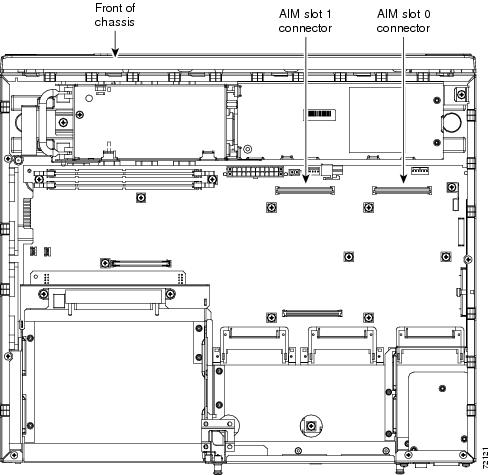
AIM Locations in Cisco 2691 Routers
VPN AIM, voice-mail AIM—You can install only one AIM, and it can go in either AIM connector.
Voice compression AIM, ATM AIM—You can install an AIM in either AIM connector, or two AIMs using both AIM connectors.
Data compression AIM—You can install one AIM in either AIM connector, or two AIMs using both AIM connectors.
Figure 11 AIM Connector Locations on System Board of Cisco 2691 Router

AIM Locations in Cisco 3631 Routers
VPN AIM—You can install one AIM.
Voice compression and ATM AIM—Not applicable.
Data compression AIM—Not applicable.
Figure 12 AIM Connector Location on System Board of Cisco 3631 Router
AIM Locations in Cisco 3725 Routers
VPN AIM, voice-mail AIM—You can install only one AIM, and it can go in either AIM connector.
Voice compression AIM, ATM AIM—You can install one AIM in either AIM connector, or two AIMs using both AIM connectors.
Data compression AIM—You can install one AIM in either AIM connector, or two AIMs using both AIM connectors.
Figure 13 AIM Connector Locations on System Board of Cisco 3725 Router
To install an AIM, complete the following procedures:
1.
2.
3.
4.
5.
7.
Removing a Hinged Cover from a Chassis
To remove a hinged cover from a Cisco router chassis, perform the following procedure. To complete this procedure you need a number 2 Phillips screwdriver or a flat-blade screwdriver.
Observe the following warning if your router uses DC power:
Warning
Step 1
Warning
Step 2
Step 3
Step 4
Step 5
Step 6
Figure 14 Removing a Hinged Cover from a Cisco Router

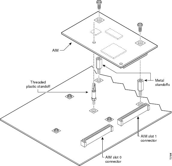
Installing an AIM in a Chassis with a Hinged Cover
Perform the following procedure for each AIM to be installed. To complete this procedure, you need a 1/4-inch nut driver and a number 2 Phillips screwdriver or a flat-blade screwdriver.
Note
Note
Step 1
Figure 15 Removing Screws from System Board—AIM Slot 1 Installation Shown
Step 2
Caution
Step 3
Step 4
Step 5
Figure 16 Connecting an AIM to the System Board—AIM Slot 1 Shown
Step 6
Figure 17 AIM Installed in AIM Slot 1
Installing a CompactFlash Memory Card on the AIM
Complete the procedure below for installing a CompactFlash memory card mounted on the AIM. To access the internal CompactFlash memory card, you need to either remove the chassis cover or slide the system board out, depending on the platform. For Cisco 3725 routers, see the "Removing a Hinged Cover from a Chassis" section.
Note
Step 1
Step 2
Step 3
Step 4
Step 5
Figure 18 CompactFlash Memory Card Location on the AIM
Figure 19 CompactFlash Memory Card Installation on the AIM
Applying the AIM Label on a Chassis with a Hinged Cover
The AIM label for the chassis might be in the AIM mounting kit, or it might be attached to the label on the AIM card. Apply the chassis label as follows:
Step 1
Step 2
Step 3
Note
Reinstalling the Cover on a Chassis with a Hinged Cover
Caution
Perform the following procedure to reinstall the router cover. You need a number 2 Phillips screwdriver or a flat-blade screwdriver to complete this procedure.
Step 1
Step 2
Step 3
Figure 20 Replacing a Hinged Cover on a 2-RU Chassis
Step 4
Step 5
Step 6
Step 7
Step 8
Observe the following warning if your Cisco router uses DC power:
Warning
Installing AIMs in a Cisco 3660 Router
Note
AIMs do not require an external network connection; they attach directly to an internal AIM connector on the Cisco 3660 system board. (See Figure 21.)
AIM Locations in Cisco 3660 Routers
VPN AIM—You can install only one AIM, and it can go in either AIM connector.
Voice compression AIM, ATM AIM—You can install one AIM in either AIM connector, or two AIMs using both AIM connectors.
Data compression AIM—You can install one AIM in either AIM connector, or two AIMs using both AIM connectors.
Voice-mail AIM—Not applicable.
Figure 21 Cisco 3660 System Board Layout

To install an AIM in a Cisco 3660 router, perform the following procedures:
1.
2.
3.
4.
6.
The sections that follow describe these procedures.
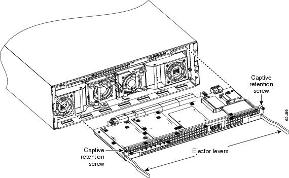
Removing the System Board Tray
This section describes the procedure for removing the Cisco 3660 system board tray. You must remove the system board tray to access the internal components.
Warning
Warning
To remove the system board tray, follow these steps:
Step 1
Step 2
Step 3
Step 4
Step 5
Figure 22 Removing the System Board Tray

Installing AIMs in a Cisco 3660 Router
Perform the following procedure for each AIM to be installed. You need a Torx-15 screwdriver, a number 2 Phillips screwdriver, and a 1/4-inch nut driver to complete this procedure.
Note
Note
Step 1
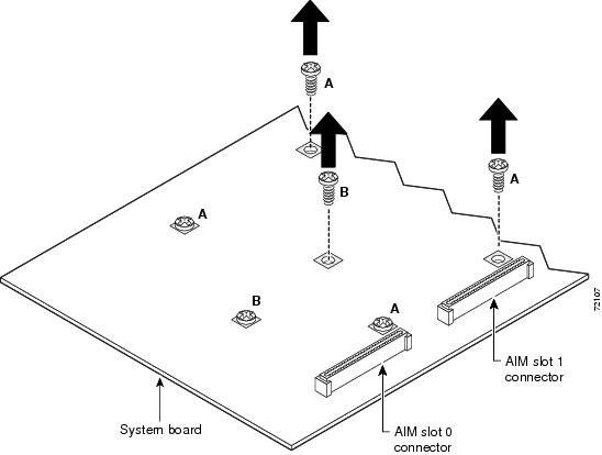
Figure 23 Removing the Three Screws from the System Board—AIM Slot 1 Installation Shown

Step 2
Caution
Step 3
Step 4
Step 5
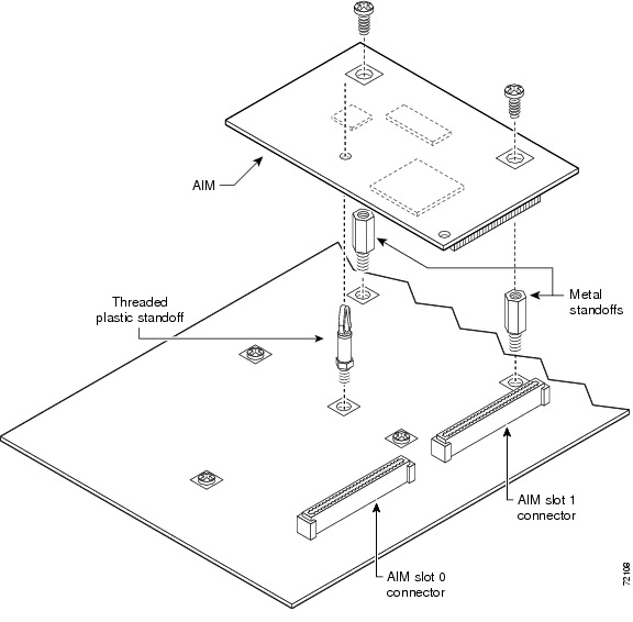
Figure 24 Connecting the AIM to the System Board
Step 6
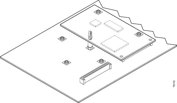
Figure 25 Installed AIM
Applying the AIM Label on a Cisco 3660 Router
The AIM label for the chassis might be in the AIM mounting kit, or it might be attached to the label on the AIM card. Apply the chassis label as follows:
Step 1
Step 2
Step 3
Figure 26 AIM Label Location
Reinstalling the System Board Tray
To reinstall the system board tray in the chassis, do the following:
Step 1
Step 2
Step 3
Step 4
Step 5
Step 6
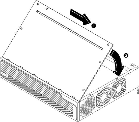
Figure 27 Reinstalling the System Board Tray
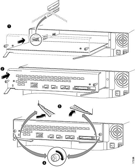
Align system board tray with guides
Rotate tray levers closed
Insert system board tray
Install captive screws
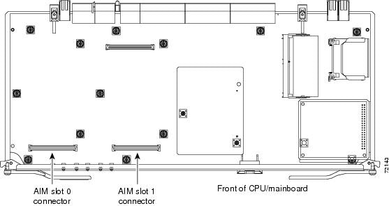
Installing AIMs in a Cisco 3745 Router
Note
This section contains procedures for installing and removing an AIM in a Cisco 3745 router. The AIM connectors are on the system board, which you can unplug and remove from the router chassis. AIM connectors are located as shown in Figure 28.
AIM Locations in Cisco 3745 Routers
VPN AIM—You can install only one AIM, and it can go in either AIM connector.
Voice compression AIM, ATM AIM—You can install one AIM in either AIM connector, or two AIMs using both AIM connectors.
Data compression AIM—You can install one AIM in either AIM connector, or two AIMs using both AIM connectors.
Voice-mail AIM—You can install only one AIM, and you must install it in the AIM slot labeled AIM1.
Caution
Figure 28 System Board Layout in a Cisco 3745 Router
To install an AIM in a Cisco 3745 router, complete the following procedures:
1.
2.
3.
5.
Removing the Plug-In System Board from a Cisco 3745 Router
Perform the following procedure to access an AIM mounted on a system board in a Cisco 3745 router. You need a number 2 Phillips or flat-blade screwdriver to perform this procedure.
Observe the following warning if your router uses AC power:
Warning
Observe the following warning if your router uses DC power:
Warning
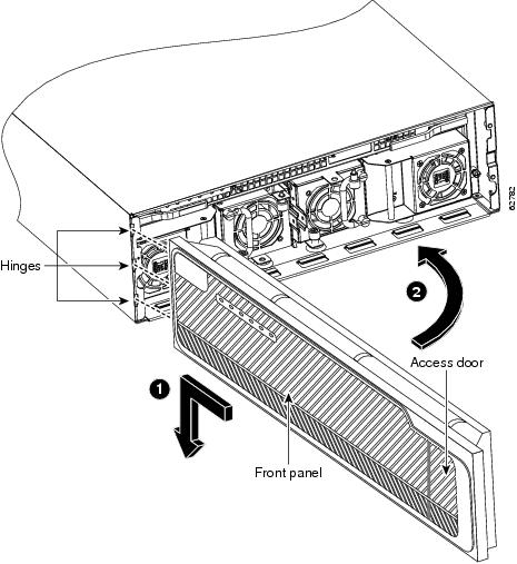
Step 1
Caution
Step 2
Step 3
Step 4
Step 5
Step 6
Step 7
Figure 29 Removing the Front Panel from a Cisco 3745 Router
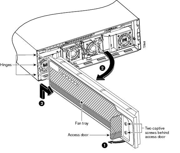
Figure 30 Removing the System board from a Cisco 3745 Router
Installing AIMs in a Cisco 3745 Router
Perform the following procedure to install an AIM. To complete this procedure, you need a 1/4-inch nut driver and a number 2 Phillips screwdriver or a flat-blade screwdriver.
Note
Note
Step 1
Caution
Figure 31 Removing the Screws from the System board (AIM Slot 1 Installation Shown)
Step 2
Caution
Step 3
Step 4
Step 5
Figure 32 Connecting an AIM to the System board (AIM Slot 1 Shown)
Step 6
Figure 33 AIM Installed in AIM Slot 1
Installing a CompactFlash Memory Card on the AIM
Complete the procedure below for installing a CompactFlash memory card mounted on the AIM. To access the internal CompactFlash memory card, you need to either remove the chassis cover or slide the system board out, depending on the platform. For Cisco 3745 routers, see the "Removing the System Board Tray" section.
Caution
Note
Step 1
Step 2
Step 3
Step 4
Step 5
Step 6
Figure 34 CompactFlash Memory Card Location on the AIM
Figure 35 CompactFlash Memory Card Installation on the AIM
Applying the AIM Label on the Cisco 3745 Router
The AIM is supplied with a two-part adhesive label that may be in the mounting kit or attached to the AIM card. Use one part of the label to identify the circuit board, and apply the other part to the outside of the chassis. Apply the labels as follows:
Step 1
Step 2
Step 3
Reinstalling the Plug-In System Board
Perform the following procedure to reinstall a plug-in system board. You need a number 2 Phillips screwdriver or a flat-blade screwdriver to perform this procedure:
Step 1
Step 2
Step 3
Figure 36 Inserting Plug-In System Board into a Cisco 3745 Chassis
Step 4
Step 5
Step 6
Observe the following warning if your router uses DC power:
Warning
Figure 37 Installing the Front Panel on a Cisco 3745 Router
Verifying AIM Installation
Use the show version command to verify that the AIM has been installed correctly. In the following example, one VPN AIM is recognized by the system (see the bold entry fourth line from last):
Router# show versionCisco Internetwork Operating System SoftwareIOS (tm) C2600 Software (C2600-JK8O3S-M), Version 12.2(1)TCopyright (c) 1986-2001 by cisco Systems, Inc.Compiled Fri 06-Apr-01 21:56Image text-base: 0x80008088, data-base: 0x81654AD0ROM: System Bootstrap, Version 12.1(3r)T1, RELEASE SOFTWARE (fc1)ROM: C2600 Software (C2600-JK8O3S-M), Version 12.2(0.18)TRouter uptime is 2 weeks, 6 days, 19 hours, 35 minutesSystem returned to ROM by power-onSystem image file is "flash:c2600-jk8o3s-mz.122-0.18.T"cisco 2651 (MPC860P) processor (revision 0x00) with 60416K/5120K bytes of memor.Processor board ID JAB043003AV (748576408)M860P processor: part number 5, mask 1Bridging software.X.25 software, Version 3.0.0.SuperLAT software (copyright 1990 by Meridian Technology Corp).TN3270 Emulation software.2 FastEthernet/IEEE 802.3 interface(s)4 Serial(sync/async) network interface(s)1 Virtual Private Network (VPN) Module(s)32K bytes of non-volatile configuration memory.32768K bytes of processor board System flash (Read/Write)Configuration register is 0x2102Use the show diag 0 command to obtain hardware information about an installed AIM. You will see additional output that is not shown in these examples.
The following example shows one ATM SAR AIM in a Cisco 2600 series router:
Router# show diag 0Slot 0:C2621 2FE Mainboard Port adapter, 4 portsPort adapter is analyzedPort adapter insertion time unknownEEPROM contents at hardware discovery:...ATM AIMATM AIM module with SAR only (no DSPs)Hardware Revision :1.0Top Assy. Part Number :800-03700-01Board Revision :A0Deviation Number :0-0Fab Version :02PCB Serial Number :JAB9801ABCD...The following example shows one ATM SAR AIM in a Cisco 3660 router:
Router# show diag 03660 Chassis type: ENTERPRISEc3600 Backplane EEPROM:Hardware Revision : 1.0Top Assy. Part Number : 800-04740-02...ATM AIM: 1ATM AIM module with SAR only (no DSPs)Hardware Revision : 1.0Top Assy. Part Number : 800-03700-01Board Revision : A0Deviation Number : 0-0Fab Version : 02PCB Serial Number : JAB9801ABCD...In Cisco 2600 series routers only, use the show pci aim command to list the installed AIMs.
The following example shows one ATM SAR AIM in a Cisco 2600 series router:
Router# show pci aimAIM Slot 0:ID 0x01B0Hardware Revision :1.0Top Assy. Part Number :800-03700-01Board Revision :A0Deviation Number :0-0Fab Version :02PCB Serial Number :JAB9801ABCDRMA Test History :00RMA Number :0-0-0-0RMA History :00EEPROM format version 4EEPROM contents (hex):0x00:04 FF 40 01 B0 41 01 00 C0 46 03 20 00 0E 74 010x10:42 41 30 80 00 00 00 00 02 02 C1 8B 4A 41 42 390x20:38 30 31 41 42 43 44 03 00 81 00 00 00 00 04 000x30:FF FF FF FF FF FF FF FF FF FF FF FF FF FF FF FF0x40:FF FF FF FF FF FF FF FF FF FF FF FF FF FF FF FF0x50:FF FF FF FF FF FF FF FF FF FF FF FF FF FF FF FF0x60:FF FF FF FF FF FF FF FF FF FF FF FF FF FF FF FF0x70:FF FF FF FF FF FF FF FF FF FF FF FF FF FF FF FFUse the show diag 0 command to obtain hardware information about an installed AIM.
The following example shows the hardware revision and additional information about encryption AIM 0 in a Cisco 3725 router:
Router# show diag 03725 Backplane EEPROM:PCB Serial Number :JAD05470J3HProcessor type :61...Encryption AIM 0:Hardware Revision :1.0Top Assy. Part Number :800-15369-02Board Revision :C0Deviation Number :0-0Fab Version :02PCB Serial Number :JAB061305B9...Use the clear aim aim-slot command to reset a specified AIM if it gets into a hung state. The following example shows an AIM in AIM slot 0 being reset:
Router# clear aim 0Configuring Internet Encryption Using Encryption AIMs
There are no configuration commands specific to the encryption hardware. Both software-based and hardware-based encryption are configured in the same way. The system automatically detects the presence of an encryption module at bootup and uses it to encrypt data; if no encryption hardware is detected, software is used to encrypt data.
To disable the VPN encryption module and revert to software encryption, enter the no crypto engine accel [0 | 1] command. To reenable the VPN encryption module, enter the crypto engine accel [0 | 1] command.
Whenever you install a new interface, or if you want to change the configuration of an existing interface, you must configure the interface. If you replace a module that was already configured, the router recognizes it and brings up the interface in the existing configuration.
For information about configuring Internet encryption, including the Internet Key Exchange (IKE) security protocol and IPSec network security, see the "IP Security and Encryption" part of the Cisco IOS Security Configuration Guide, Release 12.3 at the following URL:
http://www.cisco.com/univercd/cc/td/doc/product/software/ios123/123cgcr/sec_vcg.htm
For complete information about global configuration commands and about configuring LAN and WAN interfaces on your router, see the Cisco IOS configuration guides and command references.
Configuring Voice and ATM AIMs
For information about configuring ATM and voice processing on Cisco 2600 series and Cisco 3660 routers using AIM-ATM, AIM-VOICE-30, and AIM-ATM-VOICE-30 advanced integration modules, see the AIM-ATM, AIM-VOICE-30, and AIM-ATM-VOICE-30 on the Cisco 2600 Series and Cisco 3660 feature module on Cisco.com at the following URL:
http://www.cisco.com/univercd/cc/td/doc/product/software/ios122/122newft/122limit/122x/122xb/122xb_2/ft_gins2.htm
For complete information about global configuration commands, and about configuring ATM on your router, see the Cisco IOS configuration guides and command references.
Configuring Data Compression AIMs
There are no configuration commands specific to the compression hardware. Both software-based and hardware-based compression are configured in the same way. The system automatically detects the presence of a data compression module at startup and uses it to compress data; if no compression hardware is detected, software is used to compress data.
Note
For information about displaying statistics and about enabling and disabling data compression AIMs on specific interfaces, see the "Data Compression AIM Commands" section.
For complete information about global configuration commands, and about configuring data compression on your router, see the Cisco IOS configuration guides and command references for your Cisco IOS release.
Upgrading a PLD on Cisco 2600 Series Routers
Perform the following procedure to determine whether your Cisco 2600 series router (Cisco 2691 excepted) requires a programmable logic device (PLD) upgrade, and to do the PLD upgrade, if required.
Note
Step 1
Router#upgrade pldYou will see one of the following four messages:
Message 1No upgrade is required. Router#If you see Message 1, your router does not require a PLD upgrade. Your data compression AIM is ready for use. See the "Data Compression AIM Commands" section for information about displaying statistics and about enabling and disabling data compression AIMs on specific interfaces.Message 2A PLD is required but not available on this IOS release.Router#If you see Message 2, your router requires a PLD upgrade, but you must also install a Cisco IOS software release that supports PLD upgrade. Load any appropriate c2600 release from Cisco IOS Release 12.0, 12.1, or 12.2. After you install the new Cisco IOS software, begin again with Step 1.Message 3All WAN interface cards (WICs) must be removed during this procedure.Please power off the system, remove all WICs and issue this command again. When the procedure completes, power off the system and re-install all WIC cards into their respective slots before continuing.Router#If you see Message 3, your router requires a PLD upgrade, but you must first remove all WAN interface cards (WICs) that are installed in your router. After removing all WAN interface cards, begin again with Step 1.
Message 4PLD UPGRADE PROCEDURE. READ THESE INSTRUCTIONS CAREFULLY.This procedure will reload the hardware Programmable Logic Device (PLD). All network activity will be stopped and the router will automatically reload upon completion. You should only execute this command if you were explicitly instructed to do so. If the upgrade command is issued through a remote telnet session, there will be no confirmation on completion of the procedure, but the router will still reload normally.Note that the upgrade procedure may take up to 15 seconds to complete.During the upgrade, the router must not be interrupted.DO NOT POWER OFF THE SYSTEM DURING THE OPERATION!DOING SO MAY LEAVE THE HARDWARE IN AN INOPERABLE STATE!Proceed with PLD upgrade? [yes/no]:If you see Message 4, your router is ready for you to perform the PLD upgrade. Enter y to continue with the upgrade procedure, or enter n to stop.
Step 2
The upgrade procedure was successful. The PLD has been safely updated. The system will
automatically reload.
Step 3
Your router is now ready to power up. For information about displaying statistics and about enabling and disabling data compression AIMs on specific interfaces, see the next section, "Data Compression AIM Commands".
Data Compression AIM Commands
The following sections describe commands for displaying data compression statistics and for enabling and disabling data compression AIMs on specific interfaces.
Displaying Statistics
Use the show pas caim stats aim-slot command to display statistics describing the operation of the data compression AIM.
The command in the following example displays statistics for an AIM located in AIM slot 0 of a
Cisco 2600 series router:Router# show pas caim stats 0CompressionAim0ds:0x80F56A44 idb:0x80F50DB8422074 uncomp paks in --> 422076 comp paks out422071 comp paks in --> 422075 uncomp paks out633912308 uncomp bytes in--> 22791798 comp bytes out27433911 comp bytes in --> 633911762 uncomp bytes out974 uncomp paks/sec in--> 974 comp paks/sec out974 comp paks/sec in --> 974 uncomp paks/sec out11739116 uncomp bits/sec in--> 422070 comp bits/sec out508035 comp bits/sec in --> 11739106 uncomp bits/sec out433 seconds since last clearholdq: 0 hw_enable: 1 src_limited: 0 num cnxts: 4no data: 0 drops: 0 nobuffers: 0 enc adj errs: 0 fallbacks: 0no Replace: 0 num seq errs: 0 num desc errs: 0 cmds complete: 844151Bad reqs: 0 Dead cnxts: 0 No Paks: 0 enq errs: 0rx pkt drops: 0 tx pkt drops: 0 dequeues: 0 requeues: 0drops disabled: 0 clears: 0 ints: 844314 purges: 0no cnxts: 0 bad algos: 0 no crams: 0 bad paks: 0# opens: 0 # closes: 0 # hangs: 0Use the show compress command to display the compression ratio and other data compression statistics for a data compression AIM or for software compression.
The command in the following example displays data compression information on an interface configured for Point-to-Point Protocol (PPP) encapsulation and Stac compression:
Router# show compressSerial0/0:1Hardware compression enabledCSA in slot 0 in useuncompressed bytes xmt/rcv 0/353compressed bytes xmt/rcv 0/331Compressed bytes sent: 0 bytes 0 Kbits/secCompressed bytes recv: 331 bytes 0 Kbits/sec ratio:1.066resyncs 1last clearing of counters:25 secondsAdditional Stacker Stats:Transmit bytes: Uncompressed = 0 Compressed = 0Received bytes: Compressed = 325 Uncompressed = 0The command in the following example displays data compression information on an interface configured for PPP encapsulation and Microsoft Point-to-Point Compression (MPPC):
Router# show compressSerial0/0:1Hardware compression enabledCSA in slot 0 in useuncompressed bytes xmt/rcv 353/0compressed bytes xmt/rcv 313/0Compressed bytes sent: 313 bytes 0 Kbits/sec ratio:1.127Compressed bytes recv: 0 bytes 0 Kbits/secresyncs 1last clearing of counters:37 secondsThe command in the following example displays data compression information on an interface configured for Frame Relay encapsulation and Stac compression:
Router# show compressSerial0/0:1 - DLCI: 100Hardware compression enabledCSA in slot 0 in useuncompressed bytes xmt/rcv 0/264compressed bytes xmt/rcv 0/259Compressed bytes sent: 0 bytes 0 Kbits/secCompressed bytes recv: 259 bytes 0 Kbits/sec ratio:1.068resyncs 1last clearing of counters:21 secondsAdditional Stacker Stats:Transmit bytes: Uncompressed = 0 Compressed = 0Received bytes: Compressed = 258 Uncompressed = 0PPP Interface Configuration
The existing compression implementation for Point-to-Point Protocol (PPP) interfaces allows you to specify compression using the following commands in interface configuration mode. For more information on these commands, see the Cisco IOS configuration guides and command references for your Cisco IOS release.
•
•
•
•
•
Frame Relay Stac Configuration
Use the following Frame Relay interface commands to configure Stac compression on a per-Frame-Relay-port basis. For more information on these commands, see the Cisco IOS configuration guides and command references for your Cisco IOS release.
•
•
•
•
Use the following Frame Relay map commands to configure compression on a per data-link connection identifier (DLCI) basis. For more information on data compression AIM commands, see the Cisco IOS configuration guides and command references for your Cisco IOS release.
•
•
•
Obtaining Documentation
Cisco documentation and additional literature are available on Cisco.com. Cisco also provides several ways to obtain technical assistance and other technical resources. These sections explain how to obtain technical information from Cisco Systems.
Cisco.com
You can access the most current Cisco documentation at this URL:
http://www.cisco.com/univercd/home/home.htm
You can access the Cisco website at this URL:
You can access international Cisco websites at this URL:
http://www.cisco.com/public/countries_languages.shtml
Ordering Documentation
You can find instructions for ordering documentation at this URL:
http://www.cisco.com/univercd/cc/td/doc/es_inpck/pdi.htm
You can order Cisco documentation in these ways:
•
http://www.cisco.com/en/US/partner/ordering/index.shtml
•
Documentation Feedback
You can send comments about technical documentation to bug-doc@cisco.com.
You can submit comments by using the response card (if present) behind the front cover of your document or by writing to the following address:
Cisco Systems
Attn: Customer Document Ordering
170 West Tasman Drive
San Jose, CA 95134-9883We appreciate your comments.
Obtaining Technical Assistance
For all customers, partners, resellers, and distributors who hold valid Cisco service contracts, Cisco Technical Support provides 24-hour-a-day, award-winning technical assistance. The Cisco Technical Support Website on Cisco.com features extensive online support resources. In addition, Cisco Technical Assistance Center (TAC) engineers provide telephone support. If you do not hold a valid Cisco service contract, contact your reseller.
Cisco Technical Support Website
The Cisco Technical Support Website provides online documents and tools for troubleshooting and resolving technical issues with Cisco products and technologies. The website is available 24 hours a day, 365 days a year, at this URL:
http://www.cisco.com/techsupport
Access to all tools on the Cisco Technical Support Website requires a Cisco.com user ID and password. If you have a valid service contract but do not have a user ID or password, you can register at this URL:
http://tools.cisco.com/RPF/register/register.do
Note
Submitting a Service Request
Using the online TAC Service Request Tool is the fastest way to open S3 and S4 service requests. (S3 and S4 service requests are those in which your network is minimally impaired or for which you require product information.) After you describe your situation, the TAC Service Request Tool provides recommended solutions. If your issue is not resolved using the recommended resources, your service request is assigned to a Cisco TAC engineer. The TAC Service Request Tool is located at this URL:
http://www.cisco.com/techsupport/servicerequest
For S1 or S2 service requests or if you do not have Internet access, contact the Cisco TAC by telephone. (S1 or S2 service requests are those in which your production network is down or severely degraded.) Cisco TAC engineers are assigned immediately to S1 and S2 service requests to help keep your business operations running smoothly.
To open a service request by telephone, use one of the following numbers:
Asia-Pacific: +61 2 8446 7411 (Australia: 1 800 805 227)
EMEA: +32 2 704 55 55
USA: 1 800 553-2447For a complete list of Cisco TAC contacts, go to this URL:
http://www.cisco.com/techsupport/contacts
Definitions of Service Request Severity
To ensure that all service requests are reported in a standard format, Cisco has established severity definitions.
Severity 1 (S1)—Your network is "down," or there is a critical impact to your business operations. You and Cisco will commit all necessary resources around the clock to resolve the situation.
Severity 2 (S2)—Operation of an existing network is severely degraded, or significant aspects of your business operation are negatively affected by inadequate performance of Cisco products. You and Cisco will commit full-time resources during normal business hours to resolve the situation.
Severity 3 (S3)—Operational performance of your network is impaired, but most business operations remain functional. You and Cisco will commit resources during normal business hours to restore service to satisfactory levels.
Severity 4 (S4)—You require information or assistance with Cisco product capabilities, installation, or configuration. There is little or no effect on your business operations.
Obtaining Additional Publications and Information
Information about Cisco products, technologies, and network solutions is available from various online and printed sources.
•
http://www.cisco.com/go/marketplace/
•
http://cisco.com/univercd/cc/td/doc/pcat/
•
•
•
http://www.cisco.com/go/iqmagazine
•
•
http://www.cisco.com/en/US/learning/index.html
This document is to be used in conjunction with your router software configuration guide, the Cisco Regulatory Compliance and Safety Information document for your router, and the Cisco IOS configuration guides and command references for your Cisco IOS release.
CCSP, the Cisco Square Bridge logo, Follow Me Browsing, and StackWise are trademarks of Cisco Systems, Inc.; Changing the Way We Work, Live, Play, and Learn, and iQuick Study are service marks of Cisco Systems, Inc.; and Access Registrar, Aironet, ASIST, BPX, Catalyst, CCDA, CCDP, CCIE, CCIP, CCNA, CCNP, Cisco, the Cisco Certified Internetwork Expert logo, Cisco IOS, Cisco Press, Cisco Systems, Cisco Systems Capital, the Cisco Systems logo, Cisco Unity, Empowering the Internet Generation, Enterprise/Solver, EtherChannel, EtherFast, EtherSwitch, Fast Step, FormShare, GigaDrive, GigaStack, HomeLink, Internet Quotient, IOS, IP/TV, iQ Expertise, the iQ logo, iQ Net Readiness Scorecard, LightStream, Linksys, MeetingPlace, MGX, the Networkers logo, Networking Academy, Network Registrar, Packet, PIX, Post-Routing, Pre-Routing, ProConnect, RateMUX, ScriptShare, SlideCast, SMARTnet, StrataView Plus, SwitchProbe, TeleRouter, The Fastest Way to Increase Your Internet Quotient, TransPath, and VCO are registered trademarks of Cisco Systems, Inc. and/or its affiliates in the United States and certain other countries.
All other trademarks mentioned in this document or Website are the property of their respective owners. The use of the word partner does not imply a partnership relationship between Cisco and any other company. (0411R)
Copyright © 2003-2005 Cisco Systems, Inc. All rights reserved.


 Feedback
Contact Cisco
- Open a Support Case

- (Requires a Cisco Service Contract)
This Document Applies to These Products
- Collaboration Endpoints - Retired Products
- Conferencing - Retired Products
- Contact Center - Retired Products
- Optical Networking - Retired Products
- Routers - Retired Products
- Security - Retired Products
- Servers - Unified Computing (UCS) Retired Products
- Storage Networking Retired Products
- Switches - Retired Products
- Video - Retired Products
- Wireless - Retired Products