Table Of Contents
Installing the Cisco 10720 Internet Router
Setting up the Cisco 10720 Internet Router
Setting up the Router on a Desktop
Grounding the Cisco 10720 Internet Router
Supplemental Unit Bonding and Grounding Guidelines
Connecting Ports on the Uplink Cards
Installing the OC48 SFP Modules in the RPR/SRP Uplink Card
Creating a Four-Node IEEE 802.17 RPR Mode Ring
Additional Ports on the Uplink Cards
Attaching a Terminal Server or Access Server to the Console or AUX Port
Attaching a Modem to the Console or AUX Port
Connecting a Desktop Computer, Laptop, or Terminal to the Console or AUX Port
Connecting Ethernet Ports on the Access Card
Installing the Cable-Management System
Turning On Power to the Router
Connecting the AC Power Supply
Connecting the DC Power Supply
Verifying the Router Power Is Turned On
Configuring Global Parameters Using the Setup Facility
Verifying the Cisco 10720 Internet Router LEDs
Additional Configuration Features
Saving the Configuration to NVRAM
Using the show running configuration Command
Using the show version Command
Using the show environment all Command
Configuring Basic SRP Functionality
Configuring TDR on TX Access Card
Enabling Write Permission to Bootflash
Upgrading the Cisco IOS Software Image
Verifying the Image Is Upgraded
Verifying ROM Monitor Is Upgraded
Installing the Cisco 10720 Internet Router
Instructions for installing the Cisco 10720 Internet Router and its basic components are presented in the following sections:
•
Setting up the Cisco 10720 Internet Router
•
•
•
•
•
•
•
•
•
•
Setting up the Cisco 10720 Internet Router
Verify the following before you install the router:
•
•
•
•
•
•
•
Note
Cable Management
Install the cable-management tray, which is part of the cable-management system, onto the router before mounting the router on a rack, wall, or desktop. For instructions on installing the cable-management system, see the "Removing and Installing the Cable-Management System" section on page 5-68.
Rack-Mounting the Router
This section describes how to mount the router on an equipment rack, wall, or desktop. The router comes with three sets of brackets for rack-mounting, one set of brackets for wall-mounting, and four rubber foot pads for desk-mounting.
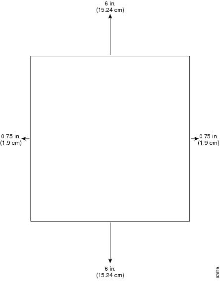
Check the clearance around the router before you install the router. See the "Required Tools and Equipment" section on page 2-5 for detailed dimension requirements.
Figure 3-1 Ventilation Requirements for Rack Mounting
Note
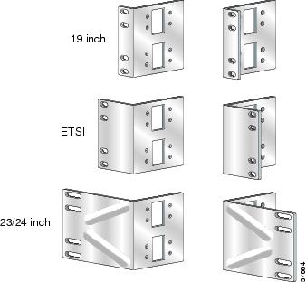
The following steps describe how to mount the router on a 19-inch EIA, 23-inch, or 24-inch EIA, or ETSI rack:
Figure 3-2 Rack-Mounting Brackets
Step 1
Step 2
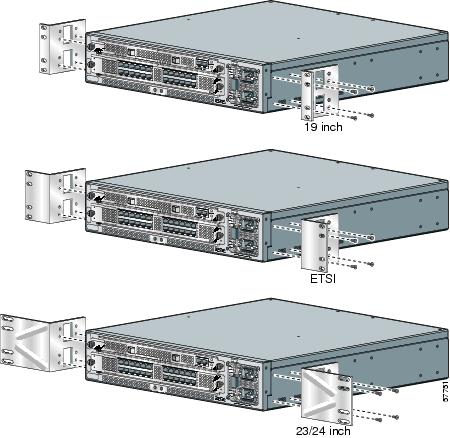
Step 3
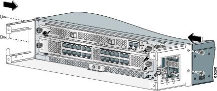
Figure 3-3 Installing Rack Mounting Brackets
Step 4
Step 5
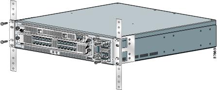
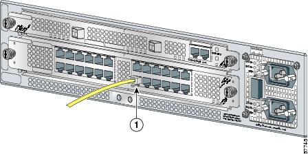
Figure 3-4 Attaching the Router to the 19-Inch Rack (Front Panel Forward)
Step 6
Use a Number 1 Phillips screwdriver to attach the four screws that are supplied in the cable accessory kit to attach each side of the router chassis to the rack. (See Figure 3-4.)
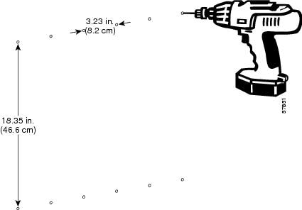
Wall-Mounting the Router
The wall-mounting brackets must be mounted on a minimum 5/8-inch (15.9 mm) gypsum wallboard or equivalent with 12 1-1/4-inch Number 10 screws or equivalent (M5 x 31.8 mm).
Caution
Perform the following steps to set up a proper and secure wall mount for the router. These steps ensure that adequate ventilation is available at all times. A Number 1 Phillips screwdriver is required to perform the following procedure:
Step 1
Note
Figure 3-5 Predrilled Holes on a Mounting Surface
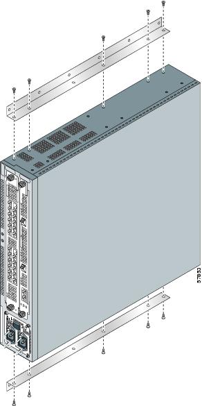
Step 2
Figure 3-6 Attaching Wall-Mounting Brackets to the Router Chassis
Note
Step 3
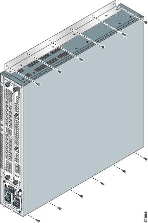
Step 4
Figure 3-7 Wall-Mount Rack
Step 5
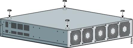
Setting up the Router on a Desktop
Use the four rubber feet included with the accessory kit to prepare the Cisco 10720 Internet Router for desktop setup. To set up the router on a desktop, perform the following steps:
Step 1
Step 2
Step 3
Figure 3-8 Applying Rubber Feet to the Bottom of the Router Chassis
Step 4
Caution
Step 5
Grounding the Cisco 10720 Internet Router
If the router is installed in a Network Equipment Building System (NEBS) environment, follow the guidelines in this section. For installations other than in a NEBS environment, you may chose to rely on the safety earth ground connection supplied via the International Electrotechnical Commission (IEC) 320 plugs for the AC power supply and DC power supply.
For additional NEBS information, see the Regulatory Compliance and Safety Information for the Cisco 10720 document.
Supplemental Unit Bonding and Grounding Guidelines
If the router is not installed in a NEBS environment, you can bypass these guidelines and rely on the safety earth ground connection supplied via the IEC 320 plugs for the AC power supply and DC power supply.
Bonding and grounding receptacles are intended to satisfy the Telcordia NEBS requirements for supplemental bonding and grounding connections. The router requires a safety earth ground connection as part of the power cabling to the AC and DC power supplies.
We strongly recommend that you connect the central office (CO) ground system or interior equipment grounding system to the chassis. Grounding to the CO system or your interior equipment grounding system meets the NEBS bonding and grounding requirement.
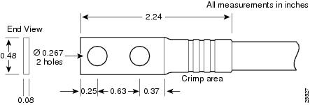
Use a dual-hole cable lug to attach it to the chassis. Use two 6.3 mm (M6) screws on the 0.63-inch (16 mm) centers as shown in Figure 3-9, Figure 3-10, and Figure 3-11. The lug can be ordered from Cisco (Part Number 32-0607-01). Grounding connectors shall be NRTL listed; use copper conductors only for grounding and bonding connectors.
Figure 3-9 Cable Lug
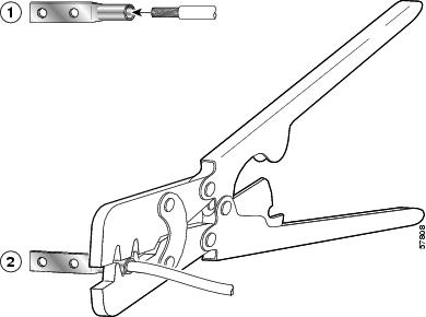
Figure 3-10 Crimping the Lug
Figure 3-11 Attaching the Grounding Lug to the Router Chassis
SONET Distance Limitations
The maximum distance for single-mode installations is determined by the amount of light loss in the fiber path. Good quality single-mode short-reach optical cable with very few splices can carry an uplink card signal 2 km. A single-mode, intermediate-reach optical cable signal can carry an uplink card signal up to 15 km.
If your environment requires the signal to travel close to the typical maximum distance, use an Optical Time Domain Reflectometer (OTDR) to measure the power loss.
Caution
Note
Fiber Cables and Connectors
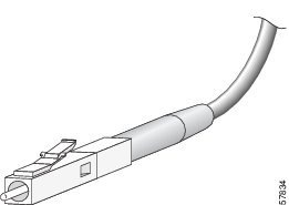
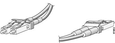
For SONET/SDH single-mode fiber-optic connections, use two simplex optical cables (see Figure 3-12) or one duplex optical cable (see Figure 3-13).
Warning
Warning
Warning
Note
Figure 3-12 Simplex Optical Cable
Figure 3-13 Duplex Optical Cable
Attach either one duplex optical cable or two simplex optical cables between the card and the device to which the card is connected. (See Figure 3-16.)
Connecting Ports on the Uplink Cards
Before connecting the ports on an uplink card, install the cable-management tray. For more information, see the "Removing and Installing the Cable-Management System" section on page 5-68.
For cable and connection specifications, refer to the Cisco 10720 Internet Router Uplink Cards Installation and Configuration publication.
To connect the ports on the DPT or POS uplink card, or the RPR/SRP uplink card, follow these instructions:
Step 1
Step 2
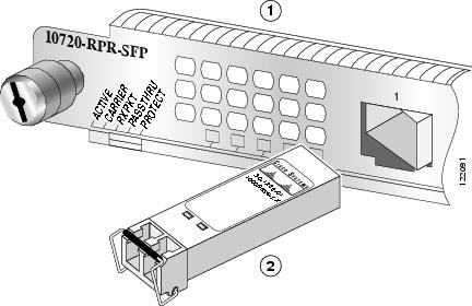
Installing the OC48 SFP Modules in the RPR/SRP Uplink Card
Use the information in this section to install OC48 SFP modules in the RPR/SRP uplink card.
Note
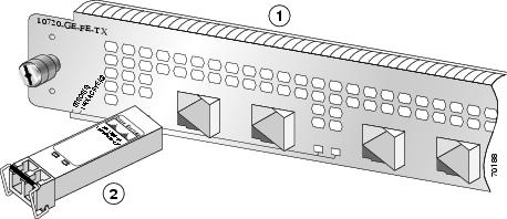
To install a bale clasp OC48 SFP module in the uplink card, perform the following steps:
Step 1
Step 2
Step 3
Caution
Figure 3-14 Installing the Bale Clasp SFP Module in the RPR/SRP Uplink Card
Step 4
Step 5
For some basic troubleshooting tips, see the "Basic Troubleshooting SRP for the Uplink Card" section.
Creating a Four-Node DPT Ring
Create a four-node DPT ring by connecting the fiber-optic cables to DPT uplink cards that are installed in routers on the network. To create a four-node DPT ring, perform the following steps:
Figure 3-15 Creating a DPT Ring Using Uplink Line Cards
Step 1
Step 2
Note
Step 3
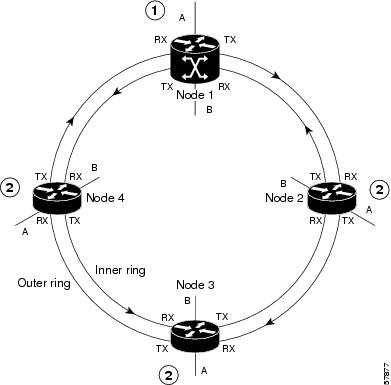
Use Figure 3-15 and Table 3-1 to help organize the cable connections for a four-node DPT ring. Figure 3-16 provides a view of the network when a four-node DPT ring is created.
Figure 3-16 Four-node DPT Ring
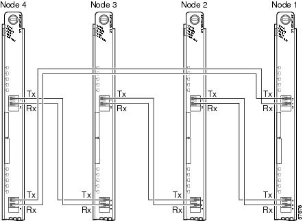
Creating a Four-Node IEEE 802.17 RPR Mode Ring
Use Figure 3-17 and Table 3-2 to help organize the cable connections for a four-node IEEE 802.17 RPR mode ring.
Figure 3-17 Creating an IEEE 802.17 RPR Mode Ring Using RPR/SRP Uplink Cards
The TX span East port on Node 1 goes to the RX span West port on the next router, which will become Node 2. The labels above the fiber connectors identify span West (left port) TX and RX, and span East (right port) TX and RX. (See Figure 3-17.)
Create a four-node IEEE 802.17 RPR mode ring by connecting the fiber-optic cables to RPR/SRP uplink cards that are installed in routers on the network. To create a four-node IEEE 802.17 RPR mode ring, perform the following steps:
Step 1
Step 2
Step 3
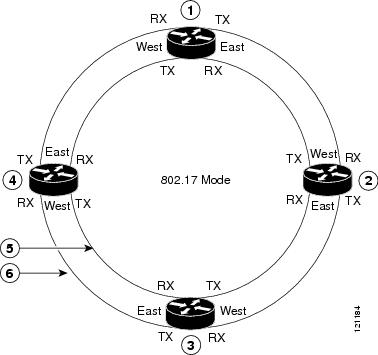
Figure 3-18 provides a view of the network when a four-node IEEE 802.17 RPR mode ring is created.
Figure 3-18 Four Node IEEE 802.17 RPR Mode Ring
Additional Ports on the Uplink Cards
You can connect the console or serial (AUX) port on the uplink cards to any of the following:
•
•
•
•
•
•
The console and AUX ports are located on the right side of the uplink card.
Note
Attaching a Terminal Server or Access Server to the Console or AUX Port
To connect a terminal server or access server to the AUX port of the router, do the following:
Note
Step 1
Step 2
Step 3
Step 4
Step 5
Step 6
Step 7
!interface Loopback0ip address 10.1.1.1 255.255.255.0no ip directed-broadcast!line 8 <=the c10720 console or AUX port is connected to line 8exec-timeout 0 0 <==(Optional) make the telnet connection over this line not to timeout forevertransport input all <==allow reverse telnetStep 8
C:> telnet 10.1.1.1 2008
Attaching a Modem to the Console or AUX Port
To connect a modem to the AUX port on the router, do the following:
Note
Step 1
Step 2
Step 3
Step 4
Step 5
Step 6
!hostname Esop!enable password Sherman!username Peabody password 0 Sherman <= user name and password for dial-in PPP authentication!interface asynchronous 1ip address 145.168.1.1 255.255.255.0no ip directed-broadcastencapsulation pppdialer in-band <= Allow asynchronous dial-inasync mode interactivepeer default ip address 150.168.1.100 <= assign a ip address to the remote PCppp authentication chap <= PPP authentication with CHAP!!line aux 0password ciscologinmodem InOut <=allow modem dial in and dial outmodem autoconfigure type usr_sportster <=specify the modem typeautoselect during-loginautoselect ppp <=Launch PPP when dial-in is successful.transport input all <=allow all types of terminal sessions, such as telnetstopbits 1speed 19200flowcontrol hardware!end
Connecting a Desktop Computer, Laptop, or Terminal to the Console or AUX Port
When a desktop computer, laptop, or terminal is connected directly to the console port, you can always access the router at any privilege level without an enable password or enable secret global configuration command configured on the router. (See the "Assigning Passwords" section.)
The AUX port requires an enable password or enable secret password configured on the router; otherwise, the desktop computer, laptop, or terminal cannot access the enable mode of the router.
The asynchronous interface (interface async 1) can be configured for line 1, which is the AUX port. The AUX port can be connected to a modem. However, no asynchronous interface can be configured for the console port; therefore, the console port cannot connect to a modem.
The console and AUX ports support different baud rates:
•
•
To connect the router to a desktop computer, laptop, or terminal via the console or AUX port, perform the following:
Step 1
Step 2
Step 3
Step 4
Note
Step 5
Table 3-3 Cisco 10720 Internet Router Default Port Configurations
Speed
9600
Data bit
8
Stop bit
2
Parity
-
Flow control
-
Step 6
Connecting Ethernet Ports on the Access Card
Install the cable-management tray before you connect the copper or optical fiber cable to a Fast Ethernet port or to an SFP module on the Gigabit Ethernet port on the access card. For more information, see the "Removing the Cable-Management System" section on page 5-68.
For cable and connection specifications, refer to the Cisco 10720 Internet Router Access Card Installation and Configuration publication. See Figure 3-21 for an example of a typical cable used for the access card.
To connect the interface cables to the access card ports, perform the following:
Step 1
Step 2
Installing a small form-factor pluggable Gigabit Ethernet (GE) (SFP) module in the access card GE port is described in the following sections:
Note
Note
Issue 3.
Installing a Bale Clasp SFP
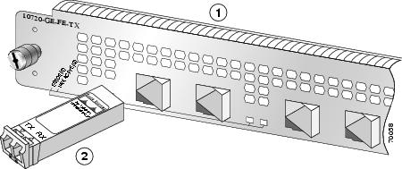
To install a bale clasp GE SFP module in the access card, perform the following steps:
Step 1
Step 2
Caution
Figure 19 Installing the Bale Clasp SFP Module in the Access Card
Caution
Step 3
Step 4
Installing a Latch SFP
To install a latch SFP module in the access card, perform the following steps:
Step 1
Step 2
Caution
Step 3
Figure 20 Installing the Latch SFP Module in the Access Card
Note
Step 4
Note
Figure 3-21 Connecting the Interface Cable (Typical)
In-Band Ethernet Port
In-band Ethernet is connected to the hub by using one of the Fast Ethernet or Gigabit Ethernet ports on the access card. Out-of-band Ethernet is not available on the Cisco 10720 Internet Router.
Installing the Cable-Management System
The cable-management system, located on the front of the router, organizes the interface cables. To keep the cables free of sharp bends, extend the cables from the center out both sides of the cable-management system. Excessive bending of an interface cable can degrade performance and possibly harm the cable.
Perform the following steps to install the cable-management system:
Step 1
Figure 3-22 Attaching the Cable-Management Tray
Step 2
Figure 3-23 Managing Router Cables with the Cable-Management Tray
Step 3
Caution
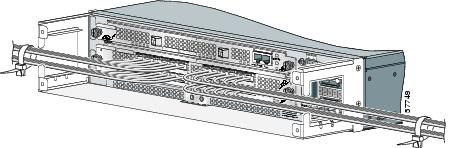
Figure 3-24 Cable-Management Tray and Router Installed in a Rack
Step 4
Figure 3-25 Installing the Cable-Management Cover
Step 5
Go to the "Turning On Power to the Router" section for information on powering on the router.
Turning On Power to the Router
Perform the following steps to restore power to the router:
•
•
Connecting the AC Power Supply
Warning
Warning
Statement 1004
Note
Note
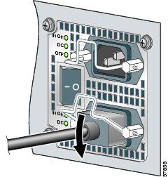
Perform the following steps to connect the AC power supply:
Step 1
Figure 3-26 AC Power Cord Connected to the Router
Step 2
Figure 3-27 Power Cord Secured with a Wire Bracket
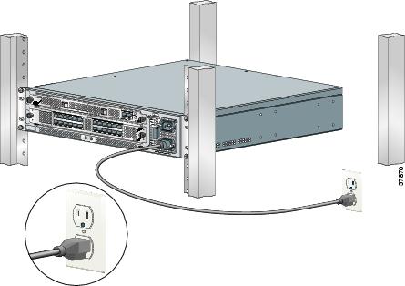
Step 3
Figure 3-28 Router Connected to the Power Source
Step 4
Figure 3-29 Power Switch in the On Position
Step 5
Connecting the DC Power Supply
Warning
Warning
Note
Connect the DC power supply by performing the following steps:
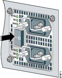
Step 1
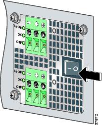
Step 2
Figure 3-30 Power Switch in the Off Position
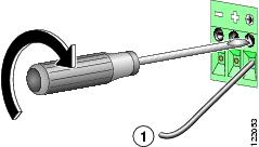
Step 3
Figure 3-31 Tightening the DC Lead Receptacle
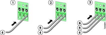
Step 4
Note
Figure 3-32 Connecting the DC Power Leads
Ground lead connected
Ground lead
Positive lead connected
Positive lead
Negative lead connected
Negative lead
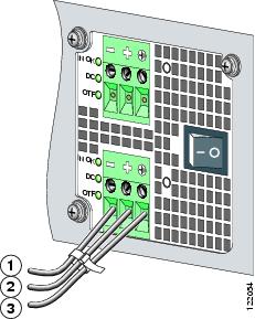
Step 5
a.
b.
c.
Figure 3-33 DC Power Leads Secured with a Cable Tie
Step 6
Note
Note
Step 7
If you are installing the cable-management system, go to the "Verifying the Router Power Is Turned On" section. If not, install the cables, and then power up the router.
Verifying the Router Power Is Turned On
Check the following to ensure the router is properly powered on:
•
•
•
Initial Setup Configuration
The initial setup configuration for the router is presented in the following sections:
•
Configuring the Router
Perform a basic configuration for the router by using either of the following methods:
•
During the startup of an unconfigured router, the system automatically starts the setup facility. The setup facility enables manual configuration of the router. The setup facility provides a structured, interactive script to set up the router.
•
You will need the following information before you set up the router:
•
•
•
•
Configuring Global Parameters Using the Setup Facility
When using the setup facility or the setup command, the system prompts the user to configure global parameters for the router. Global parameters are used for controlling system-wide settings, including the following:
•
•
•
Host Name
The name assigned to the router must follow the rules for ARPANET host names. It must start with a letter, end with a letter or digit, and have only letters, digits, and hyphens. The name must consist of 63 or fewer characters. For more information, refer to RFC 1035, Domain Names—Implementation and Specifications.
Do not expect case to be preserved. Conventions dictate that computer names appear all lowercase. For more information, refer to RFC 1178, Choosing a Name for Your Computer.
Assigning Passwords
The commands available at the user EXEC level are a subset of those available at the privileged EXEC level. Many privileged EXEC commands are used to set system parameters. You should password-protect these commands to prevent their unauthorized use. For information on how to establish password protection or configure privilege levels, refer to the "Configuring Passwords and Privileges" chapter in the Security Configuration Guide. The publication is located in the Cisco IOS software configuration documentation set that corresponds to the Cisco IOS software release installed on your Cisco hardware.
The enable secret password functionality is available for the Cisco 10720 Internet Router. Enter the correct password to gain access to privileged-level commands. When ROM monitor is active, the enable password can be used, depending on the boot ROM level.
For maximum security, the enable secret and the enable passwords should be different. If the same password is used for both the enable secret and the enable functions during the setup process, the system accepts it, but issues a warning indicating that two distinct passwords should be entered.
An enable secret password can contain from 1 to 25 uppercase and lowercase alphanumeric characters. An enable password can contain any number of uppercase and lowercase alphanumeric characters.
Verifying the Cisco 10720 Internet Router LEDs
The router LEDs are included on the access and uplink cards. The access and uplink cards each contain two sets of LEDs:
•
•
The system LEDs inform the user of the condition of the router, while the uplink or access card status LEDs inform the user of the condition or status of the card itself.
The following sections provide information about the uplink card system, uplink card status, access card system, and access card status LEDs:
Uplink Card System LEDs
Warning
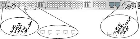
The uplink card system LEDs provide information on the functionality of the uplink card in the router. The system LEDs are located on the right side of the uplink card. See Figure 3-34 LEDs on the DPT and POS/DPT uplink cards.
Figure 3-34 DPT and POS/DPT Uplink Card LEDs (Left) and System LEDs (Right)
The configuration of the router will affect the uplink LEDs. Possible variations include optical cable connections and temperature.
Table 3-4 provides a description of the system LEDs on a DPT or POS/DPT uplink card. Table 3-5 provides a description of the LEDs on an RPR/SRP uplink card.
Note
Note
Table 3-4 DPT and POS/DPT Uplink Card System LEDs
Green (default status when initialized)
System is operating within the proper temperature range.
(inlet <104oF [40oC]; outlet <109oF [43oC])
Red/Green
Both LEDs are on, appearing orange. Systems working on warning temperature range.
(104oF [40oC] <= inlet < 122oF [50oC], 109oF [43oC] <= outlet< 127oF [53oC])
Red
System is working on critical temperature state.
(122oF [50oC] <= inlet < 149oF [65oC], 127oF [53oC] <= outlet < 167oF [75oC])
Red
A hardware failure is being detected on the uplink card. During power up, the LED will be red, even when the uplink card is powered down.
Off (default status when initialized)
Card is operational. The LED is turned off after hardware initialization.
Red
Not applicable.
Red/Green
Both LEDs are on, appears orange. This is the normal configuration during power up. Once the software loads successfully, the red LED will turn off.
Green (default status when initialized)
System is operational.
Green (default status when initialized)
The uplink card is receiving power from the system1 .
Off
Uplink card is not receiving power from the system.
1 System power up is not an indication that the uplink card is powered up. Check the card status LEDs to ensure the card is functional properly and is receiving power form the system.
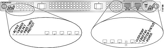
Figure 3-35 RPR/SRP Uplink System LEDs
Table 3-5 RPR/SRP Uplink Card System LEDs
Green (default status when initialized)
System is operating within the proper temperature range.
(inlet <104oF [40oC]; outlet <109oF [43oC])
Amber/green
Both LEDs are on (appears orange). System is working on warning temperature range.
(104oF [40oC] <= inlet < 122oF [50oC],
109oF [43oC] <= outlet < 127oF [53oC])Amber
System is working on critical temperature state.
(122oF [50oC] <= inlet < 149oF [65oC],
127oF [53oC] <= outlet < 167oF [75oC])Amber
A hardware failure is detected on the uplink card. During power up, the LED will be amber even when the uplink card is powered down.
Off (default status when initialized)
Card is operational. The LED is turned off after hardware initialization.
Amber
Not applicable.
Amber/green
Both LEDs are on (appears orange). This is the normal configuration during power up. Once the software loads successfully, the amber LED will turn off.
Green (default status when initialized)
System is operational.
Green (default status when initialized)
Uplink card is receiving power from the system.1
Off
Uplink card is not receiving power from the system.
1 System power up is not an indication that the uplink card is powered up. Check the card status LEDs to ensure the card is functioning properly and is receiving power from the system.
For more specific information on these and other uplink card LEDs, refer to the Cisco 10720 Internet Router Uplink Cards Installation and Configuration publication.
Uplink Card Status LEDs
Warning
The DPT/POS uplink card status LEDs provide information on the operational status of the DPT or POS uplink card. The status LEDs are located on the left side of the DPT and POS uplink cards. See Figure 3-34 for an example of a typical DPT uplink card.
Table 3-6 provides a description of status LED activity on the DPT uplink card. Table 3-7 provides a description of status LED activity on the POS/DPT uplink card. Table 3-8 provides a description of status LED activity on the RPR/SRP uplink card.
Note
1 Note that due to the SRP IP packets, this LED will remain permanently lit during normal SRP operation.
2 After you shut down the port interface on the uplink card, the RX PKT LED remains on if SRP packets (including transit SRP packets) are still being received in Pass-thru mode. The RX PKT LED turns off if no SRP packets are received.
Note
For more specific information on these and other uplink card LEDs, refer to the Cisco 10720 Internet Router Uplink Cards Installation and Configuration publication.
For additional information about laser safety requirements, see the "Laser Safety" section on page 2-4.
Access Card System LEDs
Warning
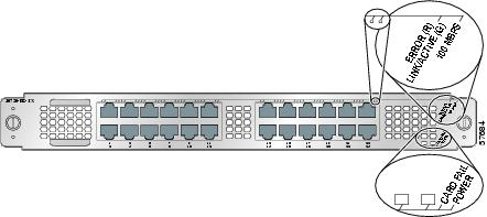
The access card system LEDs provide information on the functionality of the access card in the router. The system LEDs are located on the bottom right side of the access card. (See Figure 3-36.)
Figure 3-36 Access Card Status LEDs (Top) and System LEDs (Bottom)
The configuration of the router will affect the access LEDs. Possible variations include optical cable connections and temperature.
Table 3-9 describes the system LEDs on the access card, and indicates the system status of the access card as it initializes.
Table 3-9 System LEDs for Access Card
Red
A hardware failure is being detected on the access card. During power up, the LED will be red, even when the access card is powered down.
Off (default status when initialized)
Card is operational. The LED is turned off after hardware initialization.
Green (default status when initialized)
The access card is receiving power from the system.1
Off
The access card does not receive power from the system.
1 System power up is not an indication that the access card is powered up.
Access Card Status LEDs
Warning
The access card status LEDs provide information on the operational status of the access card. The status LEDs are located on the top right side of the access card. See Figure 3-36 for an example of typical access card status LEDs.
For a complete description of the access card LEDs, refer to the Cisco 10720 Internet Router Access Card Installation and Configuration publication.
For additional information about laser safety requirements, see the "Laser Safety" section on page 2-4.
Additional Configuration Features
The following sections provide information on additional router configuration and monitoring procedures:
•
•
•
•
•
•
Saving the Configuration to NVRAM
To save your configuration to NVRAM, use the copy running-config startup-config command.
Router# copy running-config startup-configDestination filename [startup-config]?Building configuration...[OK]Router#Using the show Commands
You can display router information using the show commands described in the following sections:
•
•
•
Using the show running configuration Command
Use the show running-configuration command to verify the router's configuration.
router# show running-configurationBuilding configuration...Current configuration : 3791 bytes ! version 12.0 no service pad service timestamps debug uptime service timestamps log uptime no service password-encryption ! hostname Router ! boot system flash:c10700-p-mz.120-18.ST ! ip subnet-zero ! ! interface SRP1/1 ip address 48.1.1.10 255.255.255.0 no ip directed-broadcast ! interface FastEthernet2/1 ip address 190.10.1.1 255.255.255.0 no ip directed-broadcast duplex auto speed auto media-type mdix ! interface FastEthernet2/2 ip address 190.10.2.1 255.255.255.0 no ip directed-broadcast duplex auto speed auto media-type mdix ! interface FastEthernet2/3 ip address 190.10.3.1 255.255.255.0 no ip directed-broadcast duplex auto speed auto media-type mdix !
(Repetitive information removed for FastEthernet2/4 to FastEthernet2/22.)
!
interface FastEthernet2/23
ip address 190.10.20.1 255.255.255.0
no ip directed-broadcast
duplex auto
speed auto
media-type mdix
!
interface FastEthernet2/24
ip address 194.16.24.1 255.255.255.0
no ip directed-broadcast
duplex auto
speed auto
media-type mdix
!
ip classless
!
snmp-server engineID local 000000090200000164FF2B00
no snmp-server ifindex persist
!
!
line con 0
exec-timeout 0 0
line aux 0
line vty 0 4
login
!
end
Using the show version Command
Use the show version command to view the currently running version of Cisco IOS software.
In the following example of the show version command, the running system software is Cisco IOS Release 12.0(19)SP:
Router# show versionCisco Internetwork Operating System SoftwareIOS (tm) 10700 Software (C10700-P-M), Version 12.0(19)SP, EARLY DEPLOYMENT RELEASE SOFTWARE (fc1)TAC Support:http://www.cisco.com/tacCopyright (c) 1986-2001 by cisco Systems, Inc.Compiled Fri 28-Sep-01 11:44 by sraniImage text-base:0x50010960, data-base:0x50660000ROM:System Bootstrap, Version 12.0(20010529:144545) [yuwang-rommon1 149], DEVELOPMENT SOFTWAREBOOTLDR:10700 Software (C10700-P-M), Version 12.0(19)SP, EARLY DEPLOYMENT RELEASE SOFTWARE (fc1)Router uptime is 10 minutesSystem returned to ROM by power-onRunning default softwarecisco C10720 (R5000) processor (revision 0xFF) with 256000K/6144K bytes of memory.R527x CPU at 200Mhz, Implementation 40, Rev 10.0Last reset from power-onToaster processor tmc0 is running.Toaster processor tmc1 is running.1 one-port OC48 SONET based SRP controller.1 24 Port 100 Mbps Fast Ethernet TX controller.24 FastEthernet/IEEE 802.3 interface(s)1 SRP network interface(s)509K bytes of non-volatile configuration memory.16384K bytes of Flash internal SIMM (Sector size 512KB).49152K bytes of Flash internal SIMM (Sector size 512KB).Configuration register is 0x2102Using the show environment all Command
Use the show environment all command to display temperature readings, voltage readings, and fan status.
router# show environment allPower Supplies: Power Supply is ok. Temperature readings: chassis inlet measured at 27C/80F chassis outlet0 measured at 33C/91F chassis outlet1 measured at 32C/89F Voltage readings: Main Board :Voltage Ok Access Card :Voltage Ok Uplink Card :Voltage Ok Fans: Fan 1 status is believed to be ok. Fan 2 status is believed to be ok. Fan 3 status is believed to be ok. Fan 4 status is believed to be ok. Power Supply Fan status is believed to be ok. Envm stats saved 1 time(s) since reload Router#Monitoring Optical Power
Optical power monitoring is used to monitor the SRP uplink interface. Use the show controllers srp command.
Router# show controllers srpInterface SRP1/1 Hardware is OC48 SRP SRP1/1 - Side A (Outer RX, Inner TX) OPTICS RX readout values: -12 dBm - Within specifications <==== HERE SECTION LOF = 0 LOS = 0 BIP(B1) = 0 LINE AIS = 0 RDI = 0 FEBE = 0 BIP(B2) = 0 PATH AIS = 0 RDI = 0 FEBE = 0 BIP(B3) = 0 LOP = 0 NEWPTR = 0 PSE = 0 NSE = 0 Active Defects: None Active Alarms: None Alarm reporting enabled for: SLOS SLOF PLOP Framing : SONET Rx SONET/SDH bytes: (K1/K2) = 0/0 S1S0 = 0 C2 = 0x16 Tx SONET/SDH bytes: (K1/K2) = 0/0 S1S0 = 0 C2 = 0x16 J0 = 0x1 Clock source : Internal Framer loopback : None Path trace buffer : Stable Remote hostname : M0415B Remote interface: SRP2/0 Remote IP addr : 48.1.1.2 Remote side id : B BER thresholds: SF = 10e-3 SD = 10e-6 IPS BER thresholds(B3): SF = 10e-3 SD = 10e-6 TCA thresholds: B1 = 10e-6 B2 = 10e-6 B3 = 10e-6 SRP1/1 - Side B (Inner RX, Outer TX) OPTICS RX readout values: -15 dBm - Within specifications <==== HERE SECTION LOF = 0 LOS = 0 BIP(B1) = 0 LINE AIS = 0 RDI = 0 FEBE = 0 BIP(B2) = 0 PATH AIS = 0 RDI = 0 FEBE = 0 BIP(B3) = 0 LOP = 0 NEWPTR = 0 PSE = 0 NSE = 0 Active Defects: None Active Alarms: None Alarm reporting enabled for: SLOS SLOF PLOP Framing : SONET Rx SONET/SDH bytes: (K1/K2) = 0/0 S1S0 = 0 C2 = 0x16 Tx SONET/SDH bytes: (K1/K2) = 0/0 S1S0 = 0 C2 = 0x16 J0 = 0x1 Clock source : Internal Framer loopback : None Path trace buffer : Stable Remote hostname : M0415B Remote interface: SRP2/0 Remote IP addr : 48.1.1.2 Remote side id : A BER thresholds: SF = 10e-3 SD = 10e-6 IPS BER thresholds(B3): SF = 10e-3 SD = 10e-6 TCA thresholds: B1 = 10e-6 B2 = 10e-6 B3 = 10e-6Configuring Basic SRP Functionality
The basic SRP configuration task for the router is located in the Cisco IOS Software Configuration for the Cisco 10720 Internet Router publication under "Configuring SRP."
Configuring POS Functionality
The basic SRP configuration task for the router is located in the Cisco IOS Software Configuration for the Cisco 10720 Internet Router publication under "Configuring POS."
Configuring Fast Ethernet
The basic Fast Ethernet configuration task for the router is located in the Cisco IOS Software Configuration for the Cisco 10720 Internet Router publication under "Configuring a Fast Ethernet Interface."
Configuring Gigabit Ethernet
The basic Gigabit Ethernet configuration task for the router is located in the Cisco IOS Software Configuration for the Cisco 10720 Internet Router publication under "Configuring a Gigabit Ethernet Interface."
Configuring TDR on TX Access Card
The Time Domain Reflectometer (TDR) sends a signal from one end of a cable and measures the time for the signal to reflect back. To detect shorts and breaks, to measure the length of the cable, and to find other physical-layer network problems, use the TDR.
The TDR is used for Fast Ethernet ports on 10/100BASE-TX and 4-Port Gigabit Ethernet 8-Port 10/100 Ethernet TX access cards. For information about how to use the TDR, refer to "Testing for a Cable Problem on a Fast Ethernet Interface" in the Cisco IOS Software Configuration for the Cisco 10720 Internet Router publication.
Assigning IP Information
To assign IP addresses to interfaces, refer to "Configuring a Fast Ethernet Connection" in the Cisco IOS Software Configuration for the Cisco 10720 Internet Router publication.
Enabling Write Permission to Bootflash
The router provides 64 MB of Flash memory. There are 16 MB dedicated to the bootflash, a read-only partition containing the Cisco IOS software image that shipped with the router. There are 48 MB dedicated to the Flash, a read-write partition containing downloaded Cisco IOS software images.
To enable the write permission to the bootflash, use the bootflash-write enable command.
router(config)# bootflash-write enable
Caution
Upgrading the Cisco IOS Software Image
You can upgrade the Cisco IOS software image on the router by copying the image to Flash memory and then restarting the router using the updated image.
Note
Perform the following steps to update the Cisco IOS software image:
Step 1
Router> enableStep 2
Router# copy tftp flashAddress or name of remote host []? tftp_serverSource filename []? /tftpboot/ image nameDestination filename [file name]? Accessing tftp://tftp_server//tftpboot/ image name!!!!!!!Step 3
Router# config terminalRouter(config)# boot system flash:image nameRouter(config)# config-register 0x2102Step 4
Router# reloadProceed with reload? [confirm] 03:36:32: %SYS-5-RELOAD: Reload requested
Note
boot system tftp <file> <tftp_server>,
rommon 1>boot <file> <tftp_server>, rommon 1>tftpdnld <file>
Verifying the Image Is Upgraded
Enter the show version command to confirm the correct image is loaded on the router. (See the "Using the show Commands" section.)
Upgrading ROM Monitor
The following section provides information for upgrading the ROM monitor (ROMmon) image. For additional information about ROMmon features, refer to the Cisco IOS Software Configuration for the Cisco 10720 Internet Router publication.
The following steps are an example ROMmon update procedure:
Step 1
Router(boot)# show rom-monitorRegion region1:INVALIDRegion region2:INVALIDCurrently running ROMMON from S (Gold) regionStep 2
Router(boot)# copy tftp flashStep 3
Router(boot)# upgrade rom-monitor file flash:nameROMMON image upgrade in progressErasing flashProgramming flashVerifying new imageROMMON image upgrade complete, router must be reloaded.Step 4
Router# show rom-monitorRegion region1:APPROVED, preferredRegion region2:INVALIDCurrently running ROMMON from region1 region
Verifying ROM Monitor Is Upgraded
To verify the upgraded ROM monitor, use the show rom-monitor command to verify that the new ROMmon is approved.
Router# show rom-monitorRegion F1: APPROVED, preferredRegion F2: INVALIDCurrently running ROMMON from F1 region