Guest

Cisco ONS 15400 Series

Installing the MXP_2.5G_10E_C and MXP_2.5G_10E_L Cards in the Cisco ONS 15454 SONET/SDH

Table Of Contents

Installing the MXP_2.5G_10E_C and MXP_2.5G_10E_L Cards in the Cisco ONS 15454 SONET/SDH

MXP_2.5G_10E_C and MXP_2.5G_10E_L Description

Feature Summary

Client and Trunk Ports

Faceplates

Client Interface Monitoring

Wavelength Identification

Card-Level Indicators

Port-Level Indicators

MXP_2.5G_10E_C Card Specifications

MXP_2.5G_10E_L Card Specifications

Install the MXP_2.5G_10E_C and MXP_2.5G_10E_L Card

Related Documentation

Obtaining Documentation

Cisco.com

Product Documentation DVD

Cisco Optical Networking Product Documentation CD-ROM

Ordering Documentation

Documentation Feedback

Cisco Product Security Overview

Reporting Security Problems in Cisco Products

Obtaining Technical Assistance

Cisco Technical Support & Documentation Website

Submitting a Service Request

Definitions of Service Request Severity

Obtaining Additional Publications and Information


Installing the MXP_2.5G_10E_C and MXP_2.5G_10E_L Cards in the Cisco ONS 15454 SONET/SDH


Note The terms "Unidirectional Path Switched Ring" and "UPSR" may appear in Cisco literature. These terms do not refer to using Cisco ONS 15xxx products in a unidirectional path switched ring configuration. Rather, these terms, as well as "Path Protected Mesh Network" and "PPMN," refer generally to Cisco's path protection feature, which may be used in any topological network configuration. Cisco does not recommend using its path protection feature in any particular topological network configuration.


Product Names: 15454-4x2.5G10EC MXP, 15454-4x2.5G10ELMXP

This document provides a card description, specifications, and installation procedure for the MXP_2.5G_10E_C and MXP_2.5G_10E_L cards. These cards are compatible with the ONS 15454 SONET (ANSI) and the ONS 15454 SDH (ETSI) shelf assemblies. As appropriate, use this document in conjunction with the Cisco ONS 15454 DWDM Procedure Guide, the Cisco ONS 15454 DWDM Reference Manual, and the Cisco ONS 15454 DWDM Troubleshooting Guide.


Note "MXP_2.5G_10E_C" is the card name that appears in Cisco Transport Controller (CTC); the same card is named "4x2.5G 10E MXP C" on the physical faceplate. "MXP_2.5G_10E_L" is the name that appears in CTC; the same card is named "4x2.5G 10E MXP L" on the physical faceplate.


This document contains the following sections:

MXP_2.5G_10E_C and MXP_2.5G_10E_L Description

MXP_2.5G_10E_C Card Specifications

MXP_2.5G_10E_L Card Specifications

Install the MXP_2.5G_10E_C and MXP_2.5G_10E_L Card

Related Documentation

Documentation Feedback

Cisco Product Security Overview

Obtaining Technical Assistance

Obtaining Additional Publications and Information

MXP_2.5G_10E_C and MXP_2.5G_10E_L Description

The MXP_2.5G_10E_C and MXP_2.5G_10E_L cards are DWDM muxponders for the ONS 15454 platform that support full optical transparency on the client side. The cards multiplex four 2.5-Gbps client signals (4 x OC48/STM-16 SFP) into a single 10-Gbps DWDM optical signal on the trunk side. The MXP_2.5G_10E_C and MXP_2.5G_10E_L cards provide wavelength transmission service for the four incoming 2.5 Gbps client interfaces. You can install MXP_2.5G_10E_C and MXP_2.5G_10E_L cards in Slots 1 to 6 and 12 to 17.


Note The MXP_2.5G_10E_C and MXP_2.5G_10E_L cards are not compatible with the MXP_2.5G_10G card, which does not support full optical transparency.


Feature Summary

For detailed information about card features refer to the Cisco ONS 15454 DWDM Reference Manual.

The MXP_2.5G_10E_C and MXP_2.5G_10E_L cards have the following high level features:

Client interface: The MXP_2.5G_10E_C and MXP_2.5G_10E_L cards provide four intermediate- or short-range 2.5Gbps, OC-48/STM-16 ports per card on the client side. Both SR-1 and IR-1 optics can be supported and the ports use SFP connectors. The client interfaces use four wavelengths in the 1310-nm, ITU 100-GHz-spaced, channel grid.

DWDM interface: The MXP_2.5G_10E_C and MXP_2.5G_10E_L cards serve as OTN multiplexers, transparently mapping four OC-48 channels asynchronously to ODU1 into one 10-Gbps trunk. For the MXP_2.5G_10E_C card, the DWDM trunk is tunable for transmission over the entire C band and for the MXP_2.5G_10E_L card, the DWDM trunk is tunable for transmission over the entire L band. Channels are spaced at 50-GHz on the ITU grid.

Multiplexing function: The muxponder is an integral part of the optically transparent ROADM network in which data payload channels and wavelengths are processed exclusively at the optical level without electrical to optical (E-O) conversion. The key function of the MXP_2.5G_10E_C and MXP_2.5G_10E_L cards is to multiplex 4 OC-48/STM16 signals onto one ITU-T G.709 OTU2 optical signal (DWDM transmission). The multiplexing mechanism allows the signal to be terminated at a far-end node by another similar card.

Digital wrapper: The digital wrapper function (ITU-T G.709 compliant) formats the DWDM wavelength so that it can be used to set up generic communication channels (GCCs) for data communications, enable forward error correction (FEC), or facilitate performance monitoring (PM). The MXP_2.5G_10E_C and MXP_2.5G_10E_L cards work with OTN devices defined in ITU-T G.709. The cards support ODU1 to OTU2 multiplexing, an industry standard method for asynchronously mapping a SONET/SDH payload into a digitally wrapped envelope.

Onboard E-FEC processor: The processor supports both standard RS (specified in ITU-T G.709) and E-FEC, which allows an improved gain on trunk interfaces with a resultant extension of the transmission range on these interfaces. The E-FEC functionality increases the correction capability of the transponder to improve performance, allowing operation at a lower OSNR compared to the standard RS (237,255) correction algorithm. A new BCH algorithm implemented in E-FEC allows recovery of an input BER up to 1E-3.

Pluggable client interface optic modules: The MXP_2.5G_10E_C and MXP_2.5G_10E_L cards have modular interfaces. Two types of small form-factor pluggables (SFPs) can be plugged into the card. These include an OC-48/STM 16 SR-1 interface with a 7-km (4.3-mile) nominal range (for short range and intra-office applications) and an IR-1 interface with a range up to 40 km (24.9 miles). SR-1 is defined in Telcordia GR-253-CORE and in I-16 (ITU-T G.957). IR-1 is defined in Telcordia GR-253-CORE and in S-16-1 (ITU-T G.957).

High level provisioning support: The cards are initially provisioned using Cisco MetroPlanner software. Subsequently, the card can be monitored and provisioned using CTC software.

Link monitoring and management: The cards use standard OC-48 OH (overhead) bytes to monitor and manage incoming interfaces. The cards pass the incoming SDH/SONET data stream and its overhead bytes transparently.

Control of layered SONET/SDH transport overhead: The cards are provisionable to terminate regenerator section overhead. This is used to eliminate forwarding of unneeded layer overhead. It can help reduce the number of alarms and help isolate faults in the network.

Automatic timing source synchronization: The MXP_2.5G_10E_C and MXP_2.5G_10E_L cards normally synchronize from the TCC2/TCC2P card. If for some reason, such as maintenance or upgrade activity, the TCC2/TCC2P is not available, the cards automatically synchronize to one of the input client interface clocks.

Configurable squelching policy: The cards can be configured to squelch the client interface output if there is LOS at the DWDM receiver or if there is a remote fault. In the event of a remote fault, the card manages MS-AIS insertion.

Y-cable protection: This protection mechanism provides redundant bidirectional paths. Two cards can be joined in a Y-cable protection group with one card assigned as the working card and the other defined as the protection card. The Y-protection mechanism is provisionable and can be set ON or OFF (OFF is the default mode). When a signal fault is detected, the protection mechanism software automatically switches between paths.

Automatic laser shutdown: A safety mechanism used in the event of a fiber cut. The ALS procedure is supported on both client and trunk interfaces. On the client interface, ALS is compliant with ITU-T G.664 (6/99). On the data application and trunk interface, the switch on and off pulse duration is greater than 60 seconds. The on and off pulse duration is user-configurable.

Jitter: For SONET and SDH signals, the MXP_2.5G_10E_C and MXP_2.5G_10E_L cards comply with Telcordia GR-253-CORE, ITU-T G.825, and ITU-T G.873 for jitter generation, jitter tolerance, and jitter transfer.

SONET/SDH configurations: You can provision a card in a linear configuration, as a BLSR/MS-SPRing, a path protection/SNCP, or a regenerator. The cards can be used in the middle of BLSR/MS-SPRing or 1+1 spans when the cards are configured for transparent termination mode.

Onboard traffic generation: The MXP_2.5G_10E_C and MXP_2.5G_10E_L cards provide internal traffic generation for testing purposes according to PRBS, SONET/SDH, or ITU-T G.709.

Client and Trunk Ports

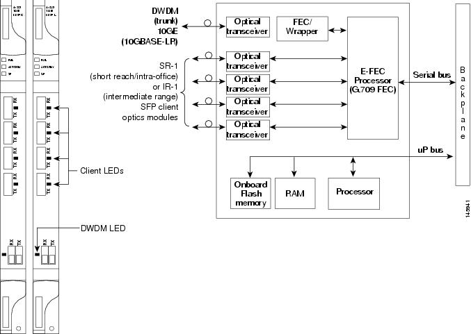
The MXP_2.5G_10E_C card features a tunable 1550-nm C-band laser on the trunk port. The laser is tunable across 82 wavelengths on the ITU grid with 50-GHz spacing between wavelengths. The MXP_2.5G_10E_L features a tunable 1580-nm L-band laser on the trunk port. The laser is tunable across 80 wavelengths on the ITU grid, also with 50-GHz spacing. Each card features four 1310-nm lasers on the client ports and contains five transmit and receive connector pairs (labeled) on the card faceplate. The cards use dual LC connectors on the trunk side and SFP modules on the client side for optical cable termination.

Faceplates

Figure 1 shows the MXP_2.5G_10E_C and MXP_2.5G_10E_L faceplates and block diagram.

Figure 1 MXP_2.5G_10E _C and MXP_2.5G_10E_L Faceplates and Block Diagram

Client Interface Monitoring

The following parameters are monitored on the MXP_2.5G_10E_C and MXP_MP_10E_L cards:

Laser bias current is measured as a PM parameter.

LOS is detected and signaled.

Rx and Tx power are monitored.

The following parameters are monitored in real time mode (one second):

Optical power transmitted (client)

Optical power received (client)

In case of LOC at the DWDM receiver or far-end LOS, the client interface behavior is configurable. AIS can be invoked or the client signal can be squelched.

Wavelength Identification

The card uses trunk lasers that are wavelocked, which allows the trunk transmitter to operate on the ITU grid effectively. Both the MXP_2.5G_10E_C and MXP_2.5G_10E_L cards implement the UT2 module. The MXP_2.5G_10E_C card uses a C-band version of the UT2 and the MXP_2.5G_10E_L card uses an L-band version.

Table 1 describes the required trunk transmit laser wavelengths for the MXP_2.5G_10E_C card. The laser is tunable over 82 wavelengths in the C band at 50-GHz spacing on the ITU grid.

Table 1 MXP_2.5G_10E_C Trunk Wavelengths 

Channel Number
Frequency (THz)
Wavelength (nm)
Channel Number
Frequency (THz)
Wavelength (nm)

1

196.00

1529.55

42

193.95

1545.72

2

195.95

1529.94

43

193.90

1546.119

3

195.90

1530.334

44

193.85

1546.518

4

195.85

1530.725

45

193.80

1546.917

5

195.80

1531.116

46

193.75

1547.316

6

195.75

1531.507

47

193.70

1547.715

7

195.70

1531.898

48

193.65

1548.115

8

195.65

1532.290

49

193.60

1548.515

9

195.60

1532.681

50

193.55

1548.915

10

195.55

1533.073

51

193.50

1549.32

11

195.50

1533.47

52

193.45

1549.71

12

195.45

1533.86

53

193.40

1550.116

13

195.40

1534.250

54

193.35

1550.517

14

195.35

1534.643

55

193.30

1550.918

15

195.30

1535.036

56

193.25

1551.319

16

195.25

1535.429

57

193.20

1551.721

17

195.20

1535.822

58

193.15

1552.122

18

195.15

1536.216

59

193.10

1552.524

19

195.10

1536.609

60

193.05

1552.926

20

195.05

1537.003

61

193.00

1553.33

21

195.00

1537.40

62

192.95

1553.73

22

194.95

1537.79

63

192.90

1554.134

23

194.90

1538.186

64

192.85

1554.537

24

194.85

1538.581

65

192.80

1554.940

25

194.80

1538.976

66

192.75

1555.343

26

194.75

1539.371

67

192.70

1555.747

27

194.70

1539.766

68

192.65

1556.151

28

194.65

1540.162

69

192.60

1556.555

29

194.60

1540.557

70

192.55

1556.959

30

194.55

1540.953

71

192.50

1557.36

31

194.50

1541.35

72

192.45

1557.77

32

194.45

1541.75

73

192.40

1558.173

33

194.40

1542.142

74

192.35

1558.578

34

194.35

1542.539

75

192.30

1558.983

35

194.30

1542.936

76

192.25

1559.389

36

194.25

1543.333

77

192.20

1559.794

37

194.20

1543.730

78

192.15

1560.200

38

194.15

1544.128

79

192.10

1560.606

39

194.10

1544.526

80

192.05

1561.013

40

194.05

1544.924

81

192.00

1561.42

41

194.00

1545.32

82

191.95

1561.83


Table 2 describes the required trunk transmit laser wavelengths for the MXP_2.5G_10E_L card. The laser is fully tunable over 80 wavelengths in the L band at 50-GHz spacing on the ITU grid.

Table 2 MXP_2.5G_10E_L Trunk Wavelengths 

Channel Number
Frequency (THz)
Wavelength (nm)
Channel Number
Frequency (THz)
Wavelength (nm)

1

190.85

1570.83

41

188.85

1587.46

2

190.8

1571.24

42

188.8

1587.88

3

190.75

1571.65

43

188.75

1588.30

4

190.7

1572.06

44

188.7

1588.73

5

190.65

1572.48

45

188.65

1589.15

6

190.6

1572.89

46

188.6

1589.57

7

190.55

1573.30

47

188.55

1589.99

8

190.5

1573.71

48

188.5

1590.41

9

190.45

1574.13

49

188.45

1590.83

10

190.4

1574.54

50

188.4

1591.26

11

190.35

1574.95

51

188.35

1591.68

12

190.3

1575.37

52

188.3

1592.10

13

190.25

1575.78

53

188.25

1592.52

14

190.2

1576.20

54

188.2

1592.95

15

190.15

1576.61

55

188.15

1593.37

16

190.1

1577.03

56

188.1

1593.79

17

190.05

1577.44

57

188.05

1594.22

18

190

1577.86

58

188

1594.64

19

189.95

1578.27

59

187.95

1595.06

20

189.9

1578.69

60

187.9

1595.49

21

189.85

1579.10

61

187.85

1595.91

22

189.8

1579.52

62

187.8

1596.34

23

189.75

1579.93

63

187.75

1596.76

24

189.7

1580.35

64

187.7

1597.19

25

189.65

1580.77

65

187.65

1597.62

26

189.6

1581.18

66

187.6

1598.04

27

189.55

1581.60

67

187.55

1598.47

28

189.5

1582.02

68

187.5

1598.89

29

189.45

1582.44

69

187.45

1599.32

30

189.4

1582.85

70

187.4

1599.75

31

189.35

1583.27

71

187.35

1600.17

32

189.3

1583.69

72

187.3

1600.60

33

189.25

1584.11

73

187.25

1601.03

34

189.2

1584.53

74

187.2

1601.46

35

189.15

1584.95

75

187.15

1601.88

36

189.1

1585.36

76

187.1

1602.31

37

189.05

1585.78

77

187.05

1602.74

38

189

1586.20

78

187

1603.17

39

188.95

1586.62

79

186.95

1603.60

40

188.9

1587.04

80

186.9

1604.03


Card-Level Indicators

Table 3 describes the three card-level LEDs on the MXP_2.5G_10E_C and MXP_2.5G_10E_L cards.

Table 3 MXP_2.5G_10E_C and MXP_2.5G_10E_L Card-Level Indicators  

Card-Level LED
Description

Red FAIL LED

The red FAIL LED indicates that the card's processor is not ready. This LED is on during reset. The FAIL LED flashes during the boot process. Replace the card if the red FAIL LED persists.

ACT/STBY LED

Green (Active)

Amber (Standby)

If the ACT/STBY LED is green, the card is operational (one or more ports active) and ready to carry traffic. If the ACT/STBY LED is amber, the card is operational and in standby (protect) mode.

Amber SF LED

The amber SF LED indicates a signal failure or condition such as LOS, LOF, or high BERs on one or more of the card's ports. The amber SF LED is also on if the transmit and receive fibers are incorrectly connected. If the fibers are properly connected and the link is working, the light turns off.


Port-Level Indicators

Table 4 lists the two port-level LEDs on the MXP_2.5G_10E_C and MXP_2.5G_10E_L cards.

Table 4 MXP_2.5G_10E_C and MXP_2.5G_10E_L Port-Level Indicators

Port-Level LED
Description

Green Client LED
(four LEDs)

A green Client LED indicates that the client port is in service and that it is receiving a recognized signal. The card has four client ports, and so has four Client LEDs.

Green DWDM LED

The green DWDM LED indicates that the DWDM port is in service and that it is receiving a recognized signal.


MXP_2.5G_10E_C Card Specifications

The MXP_2.5G_10E_C card has the following specifications:

Line (trunk side)

Bit rate: 10.70923 Gbps (in ITU-T G.709 Digital Wrapper/FEC mode)

Code: Scrambled NRZ

Fiber: 1550-nm single-mode

Maximum chromatic dispersion allowance: +/- 1200 ps/nm (specified penalty)

Loopback modes: Terminal and facility


Caution You must use a 20-dB fiber attenuator (15 to 25 dB) when working with the MXP_2.5G_10E_C card in a loopback on the trunk port. Do not use direct fiber loopbacks with the MXP_2.5G_10E_C card. Using direct fiber loopbacks causes irreparable damage to the card.

Connectors: LC

Compliance: ITU-T G.707, ITU-T G.709, ITU-T G.957, and Telcordia GR-253-CORE

Transmitter (trunk side)

Maximum transmitter output power: +6 dBm

Minimum transmitter output power: +3 dBm

Transmitter: LN external modulator transmitter

Wavelength stability (drift): +/- 25 picometers (pm)


Note An optical device on the card keeps the laser wavelength locked as closely as possible to the ITU nominal value. The allowed drift is +/- 25 pm.


Currently available wavelengths and versions of MXP_2.5G_10E_C card:

There is a single version of the MXP_2.5G_10E_C card. It is tunable across 82 wavelengths in the C-band frequency plan, with channels on the ITU 50-GHz grid, as shown in Table 1.

Line (client side)

Bit rate: 2.5 Gbps per port (OC-48/STM-16)

Code: Scrambled NRZ

Fiber: 1310-nm single-mode

Maximum chromatic dispersion allowance: 12 ps/nm (SR SFP version)

Loopback modes: Terminal and facility

Connectors: LC (optical)

Compliance: Telcordia GR-253-CORE, ITU-T G.707, ITU-T G.957

Transmitter (client side): Depends on the SFP that is used.

Receiver (client side): Depends on the SFP that is used.

Environmental

Operating temperature: -5 to +55 degrees Celsius (+23 to +113 degrees Fahrenheit)

Operating humidity: 5 to 95 percent, noncondensing

Power consumption: 50.00 W (maximum), 1.11 A at -48 V, 136.6 BTU/hr

Dimensions

Height: 12.650 in. (321.3 mm)

Width: 0.716 in. (18.2 mm)

Depth: 9.000 in. (228.6 mm)

Depth with backplane connector: 9.250 in. (235 mm)

Weight not including clam shell: 3.1 lb (1.3 kg)

MXP_2.5G_10E_L Card Specifications

The MXP_2.5G_10E_L card has the following specifications:

Line (trunk side)

Bit rate: 10.70923 Gbps (in ITU-T G.709 Digital Wrapper/FEC mode)

Code: Scrambled NRZ

Fiber: 1550-nm single-mode

Maximum chromatic dispersion allowance: +/- 1200 ps/nm (specified penalty)

Loopback modes: Terminal and facility


Caution You must use a 20-dB fiber attenuator (15 to 25 dB) when working with the MXP_2.5G_10E_L card in a loopback on the trunk port. Do not use direct fiber loopbacks with the MXP_2.5G_10E_L card. Using direct fiber loopbacks causes irreparable damage to the card.

Connectors: LC

Compliance: ITU-T G.707, ITU-T G.709, ITU-T G.957, and Telcordia GR-253-CORE

Transmitter (trunk side)

Maximum transmitter output power: +6 dBm

Minimum transmitter output power: +3 dBm

Transmitter: LN external modulator transmitter

Wavelength stability (drift): +/- 25 picometers (pm)


Note An optical device on the card keeps the laser wavelength locked as closely as possible to the ITU nominal value. The allowed drift is +/- 25 pm.


Currently available wavelengths and versions of MXP_2.5G_10E_L card:

There is a single version of the MXP_2.5G_10E_L card. It is tunable across 80 wavelengths in the L band frequency plan, with channels on the ITU 50-GHz grid, as shown in Table 2.

Line (client side)

Bit rate: 2.5 Gbps per port (OC-48/STM-16)

Code: Scrambled NRZ

Fiber: 1310-nm single-mode

Maximum chromatic dispersion allowance: 12 ps/nm (SR SFP version)

Loopback modes: Terminal and facility

Connectors: LC (optical)

Compliance: Telcordia GR-253-CORE, ITU-T G.707, ITU-T G.957

Transmitter (client side): Depends on the SFP that is used.

Receiver (client side): Depends on the SFP that is used.

Environmental

Operating temperature: -5 to +55 degrees Celsius (+23 to +113 degrees Fahrenheit)

Operating humidity: 5 to 95 percent, noncondensing

Power consumption: 50.00 W (maximum), 1.11 A at -48 V, 136.6 BTU/hr

Dimensions

Height: 12.650 in. (321.3 mm)

Width: 0.716 in. (18.2 mm)

Depth: 9.000 in. (228.6 mm)

Depth with backplane connector: 9.250 in. (235 mm)

Weight not including clam shell: 3.1 lb (1.3 kg)

Install the MXP_2.5G_10E_C and MXP_2.5G_10E_L Card


Warning During this procedure, wear grounding wrist straps to avoid ESD damage to the card. Do not directly touch the backplane with your hand or any metal tool, or you could shock yourself. Statement 94


Warning Class I (CDRH) and Class 1M (IEC) laser products. Statement 1055


Warning Invisible laser radiation may be emitted from disconnected fibers or connectors. Do not stare into beams or view directly with optical instruments. Statement 272


Note If protective clips are installed on the card connectors, remove the clips before installing the cards.


Note If you install a card incorrectly, the FAIL LED flashes continuously.


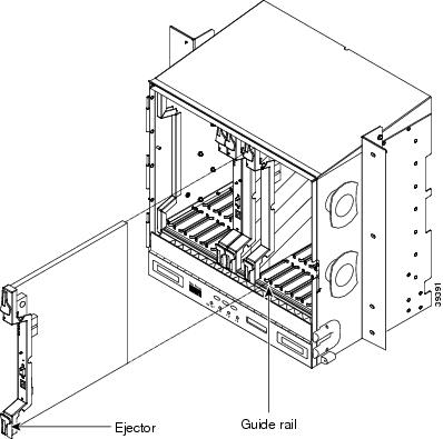
Figure 2 shows general card installation.

Figure 2 Installing a Card in the Cisco ONS 15454 SONET (ANSI) Shelf Assembly


Step 1 Display the card installation plan for the node using one of the following sources:

The Cisco MetroPlanner Site Dialog window for the node you are provisioning.

CTC node view with slots preprovisioned based on the Cisco MetroPlanner Site Dialog window.

Written slot plan. The plan must be based on the Cisco MetroPlanner Site Dialog window for your installation.

Step 2 Remove the card from its packaging, then remove the protective clips from the card's connectors.

Step 3 Open the card latches/ejectors.

Step 4 Use the latches/ejectors to firmly slide the card along the guide rails until the card plugs into the receptacle at the back of the slot.

Step 5 Verify that the card is inserted correctly and close the latches/ejectors on the card.


Note It is possible to close the latches and ejectors when the card is not completely plugged into the chassis. Ensure that you cannot insert the card any further.


Step 6 Verify the LED activity:

The red FAIL LED turns on for 20 to 30 seconds.

The red FAIL LED blinks for 35 to 45 seconds.

All LEDs blink once and turn off for 5 to 10 seconds.

The ACT or ACT/STBY LED turns on. The SF LED can persist until all card ports connect to their far-end counterparts and a signal is present.

Step 7 If the card does not boot up properly, or the LED activity does not occur as described in Step 6, check the following:

When a physical card type does not match the type of card provisioned for that slot in CTC, the card might not boot. If a card does not boot, open CTC and ensure that the slot is not provisioned for a different card type before assuming that the card is faulty.

If the red FAIL LED does not turn on, check the power.

If you insert a card into a slot provisioned for a different card, all LEDs turn off.

If the red FAIL LED is on continuously or the LEDs behave erratically, the card is not installed properly. Remove the card and repeat Steps 3 to 6.

Stop. You have completed this procedure.


Related Documentation

Cisco ONS 15454 DWDM Reference Manual

Cisco ONS 15454 DWDM Procedure Guide

Cisco ONS 15454 DWDM Troubleshooting Guide

Cisco MetroPlanner DWDM Operations Guide

Obtaining Documentation

Cisco documentation and additional literature are available on Cisco.com. Cisco also provides several ways to obtain technical assistance and other technical resources. These sections explain how to obtain technical information from Cisco Systems.

Cisco.com

You can access the most current Cisco documentation at this URL:

http://www.cisco.com/techsupport

You can access the Cisco website at this URL:

http://www.cisco.com

You can access international Cisco websites at this URL:

http://www.cisco.com/public/countries_languages.shtml

Product Documentation DVD

Cisco documentation and additional literature are available in the Product Documentation DVD package, which may have shipped with your product. The Product Documentation DVD is updated regularly and may be more current than printed documentation.

The Product Documentation DVD is a comprehensive library of technical product documentation on portable media. The DVD enables you to access multiple versions of hardware and software installation, configuration, and command guides for Cisco products and to view technical documentation in HTML. With the DVD, you have access to the same documentation that is found on the Cisco website without being connected to the Internet. Certain products also have .pdf versions of the documentation available.

The Product Documentation DVD is available as a single unit or as a subscription. Registered Cisco.com users (Cisco direct customers) can order a Product Documentation DVD (product number DOC-DOCDVD=) from Cisco Marketplace at this URL:

http://www.cisco.com/go/marketplace/

Cisco Optical Networking Product Documentation CD-ROM

Optical networking-related documentation, including Cisco ONS 15xxx product documentation, is available in a CD-ROM package that ships with your product. The Optical Networking Product Documentation CD-ROM is updated periodically and may be more current than printed documentation.

Ordering Documentation

Beginning June 30, 2005, registered Cisco.com users may order Cisco documentation at the Product Documentation Store in the Cisco Marketplace at this URL:

http://www.cisco.com/go/marketplace/

Nonregistered Cisco.com users can order technical documentation from 8:00 a.m. to 5:00 p.m. (0800 to 1700) PDT by calling 1 866 463-3487 in the United States and Canada, or elsewhere by calling 011 408 519-5055. You can also order documentation by e-mail at tech-doc-store-mkpl@external.cisco.com or by fax at 1 408 519-5001 in the United States and Canada, or elsewhere at 011 408 519-5001.

Documentation Feedback

You can rate and provide feedback about Cisco technical documents by completing the online feedback form that appears with the technical documents on Cisco.com.

You can send comments about Cisco documentation to bug-doc@cisco.com.

You can submit comments by using the response card (if present) behind the front cover of your document or by writing to the following address:

Cisco Systems
Attn: Customer Document Ordering
170 West Tasman Drive
San Jose, CA 95134-9883

We appreciate your comments.

Cisco Product Security Overview

Cisco provides a free online Security Vulnerability Policy portal at this URL:

http://www.cisco.com/en/US/products/products_security_vulnerability_policy.html

From this site, you can perform these tasks:

Report security vulnerabilities in Cisco products.

Obtain assistance with security incidents that involve Cisco products.

Register to receive security information from Cisco.

A current list of security advisories and notices for Cisco products is available at this URL:

http://www.cisco.com/go/psirt

If you prefer to see advisories and notices as they are updated in real time, you can access a Product Security Incident Response Team Really Simple Syndication (PSIRT RSS) feed from this URL:

http://www.cisco.com/en/US/products/products_psirt_rss_feed.html

Reporting Security Problems in Cisco Products

Cisco is committed to delivering secure products. We test our products internally before we release them, and we strive to correct all vulnerabilities quickly. If you think that you might have identified a vulnerability in a Cisco product, contact PSIRT:

Emergencies — security-alert@cisco.com

An emergency is either a condition in which a system is under active attack or a condition for which a severe and urgent security vulnerability should be reported. All other conditions are considered nonemergencies.

Nonemergencies — psirt@cisco.com

In an emergency, you can also reach PSIRT by telephone:

1 877 228-7302

1 408 525-6532


Tip We encourage you to use Pretty Good Privacy (PGP) or a compatible product to encrypt any sensitive information that you send to Cisco. PSIRT can work from encrypted information that is compatible with PGP versions 2.x through 8.x.

Never use a revoked or an expired encryption key. The correct public key to use in your correspondence with PSIRT is the one linked in the Contact Summary section of the Security Vulnerability Policy page at this URL:

http://www.cisco.com/en/US/products/products_security_vulnerability_policy.html

The link on this page has the current PGP key ID in use.


Obtaining Technical Assistance

Cisco Technical Support provides 24-hour-a-day award-winning technical assistance. The Cisco Technical Support & Documentation website on Cisco.com features extensive online support resources. In addition, if you have a valid Cisco service contract, Cisco Technical Assistance Center (TAC) engineers provide telephone support. If you do not have a valid Cisco service contract, contact your reseller.

Cisco Technical Support & Documentation Website

The Cisco Technical Support & Documentation website provides online documents and tools for troubleshooting and resolving technical issues with Cisco products and technologies. The website is available 24 hours a day, at this URL:

http://www.cisco.com/techsupport

Access to all tools on the Cisco Technical Support & Documentation website requires a Cisco.com user ID and password. If you have a valid service contract but do not have a user ID or password, you can register at this URL:

http://tools.cisco.com/RPF/register/register.do


Note Use the Cisco Product Identification (CPI) tool to locate your product serial number before submitting a web or phone request for service. You can access the CPI tool from the Cisco Technical Support & Documentation website by clicking the Tools & Resources link under Documentation & Tools. Choose Cisco Product Identification Tool from the Alphabetical Index drop-down list, or click the Cisco Product Identification Tool link under Alerts & RMAs. The CPI tool offers three search options: by product ID or model name; by tree view; or for certain products, by copying and pasting show command output. Search results show an illustration of your product with the serial number label location highlighted. Locate the serial number label on your product and record the information before placing a service call.


Submitting a Service Request

Using the online TAC Service Request Tool is the fastest way to open S3 and S4 service requests. (S3 and S4 service requests are those in which your network is minimally impaired or for which you require product information.) After you describe your situation, the TAC Service Request Tool provides recommended solutions. If your issue is not resolved using the recommended resources, your service request is assigned to a Cisco engineer. The TAC Service Request Tool is located at this URL:

http://www.cisco.com/techsupport/servicerequest

For S1 or S2 service requests or if you do not have Internet access, contact the Cisco TAC by telephone. (S1 or S2 service requests are those in which your production network is down or severely degraded.) Cisco engineers are assigned immediately to S1 and S2 service requests to help keep your business operations running smoothly.

To open a service request by telephone, use one of the following numbers:

Asia-Pacific: +61 2 8446 7411 (Australia: 1 800 805 227)
EMEA: +32 2 704 55 55
USA: 1 800 553-2447

For a complete list of Cisco TAC contacts, go to this URL:

http://www.cisco.com/techsupport/contacts

Definitions of Service Request Severity

To ensure that all service requests are reported in a standard format, Cisco has established severity definitions.

Severity 1 (S1)—Your network is "down," or there is a critical impact to your business operations. You and Cisco will commit all necessary resources around the clock to resolve the situation.

Severity 2 (S2)—Operation of an existing network is severely degraded, or significant aspects of your business operation are negatively affected by inadequate performance of Cisco products. You and Cisco will commit full-time resources during normal business hours to resolve the situation.

Severity 3 (S3)—Operational performance of your network is impaired, but most business operations remain functional. You and Cisco will commit resources during normal business hours to restore service to satisfactory levels.

Severity 4 (S4)—You require information or assistance with Cisco product capabilities, installation, or configuration. There is little or no effect on your business operations.

Obtaining Additional Publications and Information

Information about Cisco products, technologies, and network solutions is available from various online and printed sources.

Cisco Marketplace provides a variety of Cisco books, reference guides, documentation, and logo merchandise. Visit Cisco Marketplace, the company store, at this URL:

http://www.cisco.com/go/marketplace/

Cisco Press publishes a wide range of general networking, training and certification titles. Both new and experienced users will benefit from these publications. For current Cisco Press titles and other information, go to Cisco Press at this URL:

http://www.ciscopress.com

Packet magazine is the Cisco Systems technical user magazine for maximizing Internet and networking investments. Each quarter, Packet delivers coverage of the latest industry trends, technology breakthroughs, and Cisco products and solutions, as well as network deployment and troubleshooting tips, configuration examples, customer case studies, certification and training information, and links to scores of in-depth online resources. You can access Packet magazine at this URL:

http://www.cisco.com/packet

iQ Magazine is the quarterly publication from Cisco Systems designed to help growing companies learn how they can use technology to increase revenue, streamline their business, and expand services. The publication identifies the challenges facing these companies and the technologies to help solve them, using real-world case studies and business strategies to help readers make sound technology investment decisions. You can access iQ Magazine at this URL:

http://www.cisco.com/go/iqmagazine

or view the digital edition at this URL:

http://ciscoiq.texterity.com/ciscoiq/sample/

Internet Protocol Journal is a quarterly journal published by Cisco Systems for engineering professionals involved in designing, developing, and operating public and private internets and intranets. You can access the Internet Protocol Journal at this URL:

http://www.cisco.com/ipj

Networking products offered by Cisco Systems, as well as customer support services, can be obtained at this URL:

http://www.cisco.com/en/US/products/index.html

Networking Professionals Connection is an interactive website for networking professionals to share questions, suggestions, and information about networking products and technologies with Cisco experts and other networking professionals. Join a discussion at this URL:

http://www.cisco.com/discuss/networking

World-class networking training is available from Cisco. You can view current offerings at this URL:

http://www.cisco.com/en/US/learning/index.html


Printed in the USA on recycled paper containing 10% postconsumer waste.