Installing the Cisco ONS 15454 DWDM Passive Optical Modules
Introduction
This document explains how to install and operate the Cisco ONS 15454 DWDM passive optical modules, the fiber shuffle, and the MPO fan-out unit.
The passive optical modules are used to build the optical network system. The fiber shuffle and MPO fan-out unit mechanically holds 14 and 10 passive optical modules respectively, thus enabling interconnection of flex spectrum ROADM nodes that contain 16-WXC or SMR-FS cards.
The passive optical modules, fiber shuffle, and MPO fan-out unit can be installed on:
- 19-inch (482.6 mm) or 23-inch (584.2 mm) EIA standard racks
- 19-inch (482.6 mm) IEC rack
- 600 mm x 600 mm or 600 mm x 300 mm ETSI rack
The following table lists the PIDs of the fiber shuffle and MPO fan-out unit:
|
Module |
Description |
|---|---|
| NCS2K-MF-6RU= (MF-6RU) |
The MF-6RU unit is referred to as the fiber shuffle. A combination of 14 single-slot NCS2K-MF-DEG-5 (NCS2K-MF-DEG-5-CV) and NCS2K-MF-UPG-4 (NCS2K-MF-UPG-4-CV) passive optical modules can be installed in this unit. It is also possible to install a combination of 14 single-slot NCS2K-MF-2MPO-ADP, NCS2K-MF-4x4-COFS, NCS2K-MF-MPO-8LC, and NCS2K-MF-6AD-CFS passive optical modules. |
|
NCS2K-MF10-6RU= (MF10-6RU) |
The MF10-6RU unit is referred to as the MPO fan-out unit. A combination of 10 double-slot NCS2K-MF-10AD-CFS, NCS2K-MF-16AD-CFS, NCS2K-MF-16AE-CFS, NCS2K-MF-MPO-16LC (NCS2K-MF-M16LC-CV), NCS2K-MF-MPO-20LC, and NCS2K-MF-8X10G-FO units can be installed in this unit. |
| NCS2K-MF-1SL-CVR= |
Blank unit for the MF-6RU unit. |
| NCS2K-MF-2SL-CVR= |
Blank unit for the MF-10-6RU unit. |
|
NCS2K-USB3-CBL-2= |
USB cable; two meters long |
|
NCS2K-USB3-CBL-3= |
USB cable; three meters long |
|
NCS2K-MF-6RU-CVR= |
Plastic transparent cover for the MF-6RU and MF-10-6RU unit. |
All passive optical modules, (except the mesh patch panel module), are installed using the rack mounting bracket that is one rack unit (RU) high and can be directly connected to the NCS 2015 ECU. The passive optical modules can also be installed in the fiber shuffle or MPO fan-out unit.
The following table lists the passive optical modules:
|
Module |
Description |
|---|---|
|
NCS2K-MF-16AD-CFS= |
16-channel colorless omni-directional add/drop |
|
NCS2K-MF-4X4-COFS= |
4-channel colorless omni-directional add/drop |
|
NCS2K-MF-MPO-8LC= |
MPO to 8-LC adapter |
|
NCS2K-MF-DEG-5= |
5-degree mesh module |
|
NCS2K-MF-UPG-4= |
4-degree upgrade module |
|
NCS2K-MF-MPO-16LC= |
MPO-16 to 16-LC fan-out module |
|
NCS2K-MF-2MPO-ADP= |
Double MPO-16 to two MPO-8 adapter module |
|
NCS2K-MF-16AE-CFS= |
16-port add/drop module with express capability |
|
NCS2K-MF-10AD-CFS= |
10-port add/drop module |
|
NCS2K-PPMESH8-5AD= |
8-degree mesh patch panel with 5 add/drop ports |
|
NCS2K-MF-DEG-5-CV= |
5-degree mesh connection verification module with MPO-8 loopback caps (NCS2K-MPO-LBK=) |
|
NCS2K-MF-UPG-4-CV= |
4-degree upgrade connection verification module with MPO-8 loopback caps (NCS2K-MPO-LBK=) |
|
NCS2K-MF-M16LC-CV= |
MPO-16 to 16-LC fan-out connection verification module with LC loopback caps (NCS2K-LC-LBK=) |
|
NCS2K-MF-MPO-20LC |
MPO-24 to 20-LC fan-out module |
|
NCS2K-MF-6AD-CFS= |
Splitter/coupler module with six ports used as colorless or gridless add/drop units in NCS2K ROADM configurations. |
|
NCS2K-MF-8X10G-FO= |
MPO to LC fan-out module used as client interconnection for the NCS2K and NCS4K line cards using QSFP+ ports. |
- All modules can be used to accommodate the ROADM nodes built with the SMR-FS and AD-FS cards.
- A set of photodiodes are included on selected ports of each module for optical power monitoring.
- USB communication channel can be used to retrieve the optical power levels monitored by the photodiodes and the inventory and insertion loss (IL) data of the optical paths stored in the modules. The USB channel can also be used to activate electrical actuators or LEDs present on the front panel of the module.
- The xx SMR9 FS, SMR20 FS, or SMR20 FS CV and the 12-AD-FS or 16-AD-FS cards can be interconnected by the NCS2K-MF-UPG-4=, NCS2K-MF-UPG-4-CV=, NCS2K-MF-DEG-5=, NCS2K-MF-DEG-5-CV=, NCS2K-MF-MPO-16LC=, NCS2K-MF-M16LC-CV=, NCS2K-MF-2MPO-ADP=, or the NCS2K-PPMESH8-5AD= module.
- The NCS2K-MF-16AE-CFS= and the NCS2K-MF-10AD-CFS= modules are only used as a passive add/drop modules in the Not-DWDM networks.
The following table lists the MPO cables that can be used with the passive modules from Release 10.6.1:
|
MPO Cables |
Description |
|---|---|
|
ONS-MPO-16LC-2 |
Fan-out cable with one MPO-24 connector on one side and 16 LC connectors on the other side. The cable is two meters long and can be used in ROADM configurations with the NCS2K-MF-6AD-CFS module. This cable can also be used as a fan-out cable to connect the LC interface directly to the SMR20 FS MPO ports. |
|
ONS-12MPO-MPO-x |
Multi-fiber patch cord with MPO-12 connectors. The 12 fibers have straight connections. There are four variants: two, four, six, and eight meters.
The cables can interconnect the QSFP+ client ports of NCS2K-400G-2C2 and NCS4K-4H-OPW-QC2 with the NCS2K-MF-8X10G-FO passive module. |
|
ONS-12MPO-XMPO-x |
Multi-fiber patch cord with MPO-12 connectors. The 12 fibers have crossed fiber interconnections. There are four variants: two, four, six, and eight meters.
The cable is used to interconnect the NCS2K-MF-DEG-5-CV and the NCS2K-MF-UPG-4-CV passive modules with the NCS2K-MF-MPO-8LC adapter. |
|
ONS-16MPO-MPO-x |
Multi-fiber patch cord with MPO-24 connectors that has only 16 fibers connected. Fibers 1, 2, 11, 12, 13, 14, 23, and 24 are not connected. There are four variants: two, four, six, and eight meters.
The cable is used for interconnections inside the ROADM with MPO-24 standard. The patch cord can be used for interconnections between SMR20 FS and NCS2K-MF-M16LC-CV, or NCS2K-MF-2MPO-ADP or NCS2K-PPMESH8-5AD. The patch cord can also be used for interconnections between NCS2K-16-AD-CCOFS and NCS2K-MF-M16LC-CV. |
Safety Information
Before you install, operate, or service the passive optical modules, you must read the Regulatory Compliance and Safety Information for Cisco Optical Transport Products document for important safety information and warning translations.
The passive optical modules are compliant with the GR 1089, UL60950 /CSA 22.2 No. 60950-00, and IEC 60950 standards.
Laser Radiation Emission Restrictions
The Class 1M Laser safety and warning label affixed to the passive optical modules indicate that the product should never be used or installed in an optical network with emissions higher than Class 1M.
 Warning |
Class 1M laser radiation when open. Do not view directly with optical instruments. Statement 281 |
Laser Safety During Operation
Warning |
Invisible laser radiation may be emitted from disconnected fibers or connectors. Do not stare into beams or view directly with optical instruments. Statement 1051 |
Electrical Safety
The passive optical modules are optically and electrically passive and require no electrical connections. No electrostatic discharge (ESD) or other electrical safety considerations apply.
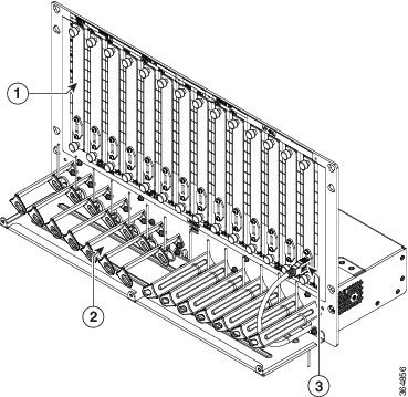
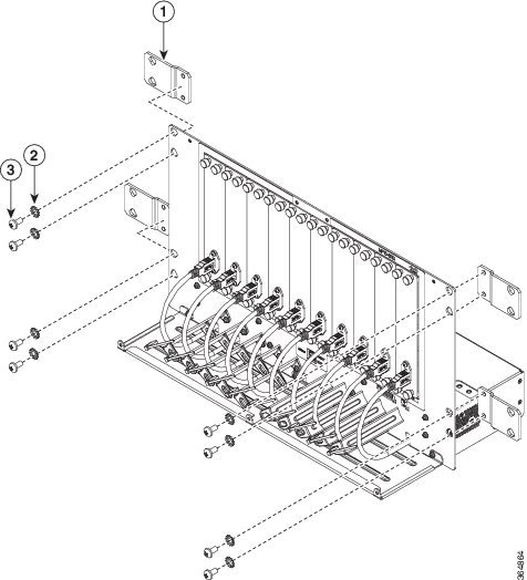
Fiber Shuffle
The MF-6RU unit is six RU high and can be used to interface 14 single slot passive optical modules with the NCS 2015 ECU. It contains a USB 3.0 hub that consolidates all USB 2.0 connections between the passive optical modules units and the NCS 2015 ECU using a single USB cable. It allows connections between line cards and optical passive modules units using simple cabling. The slots are covered by blank units. The MF-6RU unit is shipped with USB connectors connected to the corresponding blank units. A plastic transparent door can be installed in front of the unit for fiber and cable management. Mounting brackets are shipped with the unit.
|
1 |
Blank unit |
2 |
Cable guide |
|
3 |
USB connector |
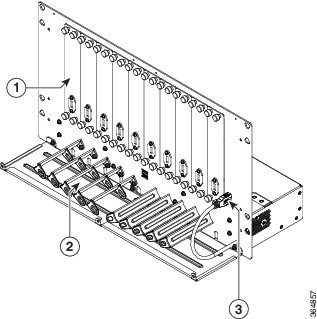
MPO Fan-out Unit
The MF10-6RU unit is six RU high and can be used to interface 10 double slot passive optical modules with the NCS 2015 ECU. It contains a USB 3.0 hub that consolidates all USB 2.0 connections between the passive optical modules units and the NCS 2015 ECU using a single USB cable. It allows connections between line cards and optical passive modules units using simple cabling. It also has an additional USB 3.0 port on its faceplate that allows it to be connected to only one MF10-6RU unit.
The slots are covered by blank units and USB connectors are connected to the corresponding blank units. A plastic transparent door can be installed in front of the unit for fiber and cable management. Mounting brackets are shipped with the unit.
|
1 |
Blank unit |
2 |
Cable guide |
|
3 |
USB connector |
||
This procedure describes the steps to install the MF-6RU or MF10-6RU unit on the ANSI or ETSI equipment rack.
Procedure
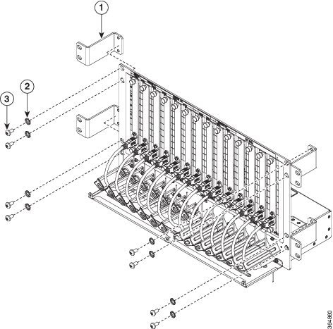
| Step 1 |
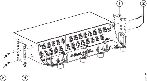
For a 23-inch ANSI or 21-inch ETSI rack installation, mount the four brackets on the MF-6RU unit (Mounting Brackets on the MF-6RU Unit for a 23-inch ANSI Rack Installation and Mounting Brackets on the MF-6RU Unit for a 21-inch ETSI Rack Installation) or MF10-6RU unit (Mounting Brackets on the MF10-6RU Unit for a 23-inch ANSI Rack Installation and Mounting Brackets on the MF-6RU Unit for a 21-inch ETSI Rack Installation):Place the mounting bracket flush against the MF-6RU or MF-0-6RU unit. Align the mounting bracket screw holes against the MF-6RU or MF10-6RU unit screw holes. Insert the M6 screws and tighten them. Repeat steps 1a through 1c to mount the remaining three brackets on the unit. 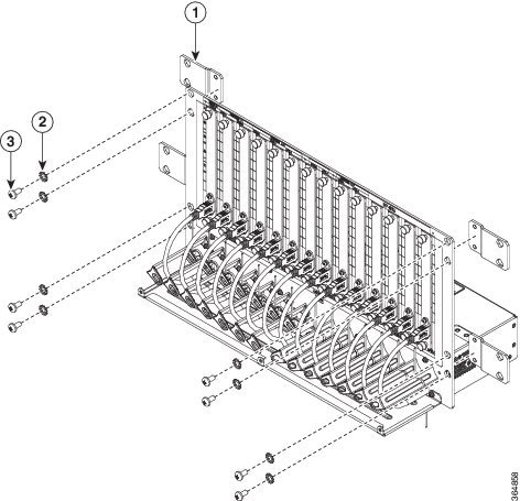

|
||||||||||||||||||||||||||||||||
| Step 2 |
Install the MF-6RU or MF10-6RU unit on the appropriate rack equipment:
|
||||||||||||||||||||||||||||||||
| Step 3 |
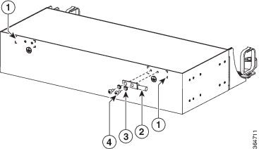
Establish grounding for the MF-6RU or MF10-6RU unit:
|
||||||||||||||||||||||||||||||||


Installing Transparent Door on MF-6RU or MF10-6RU Unit
This procedure describes the steps to install the transparent door on the MF-6RU or MF10-6RU unit.
Procedure
| Step 1 |
Install the top cover on the MF-6RU or MF10-6RU unit using four M3 screws. |
||||
| Step 2 |
Before installing the door, adjust the cable guide tray so that the door screws are properly aligned. |
||||
| Step 3 |
Install the transparent door to the MF-6RU or MF10-6RU (Figure 10) unit using six self-clinching screws. 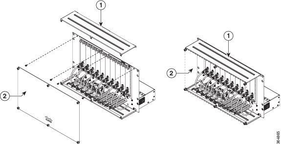
|
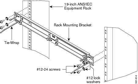
Rack Mounting Bracket
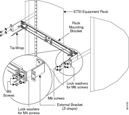
All passive optical modules, except the 8-degree mesh patch panel module, are installed using the rack mounting bracket (15216-HD-EXT-PNL=). The rack mounting bracket is 19 inches (482.6-mm) wide and can be mounted on a 19-inch (482.6-mm) ANSI or an IEC equipment rack. However, by using a pair of external brackets (either straight or Z-shaped), it can also be mounted on a 23-inch (584.2-mm) ANSI, a 600 x 600 mm (23.6 x 23.6-inch), or a 600 x 300 mm (23.6 x 11.8-inch) equipment rack.
The Cisco ONS 15454 passive optical modules size can be single slot or double slot.
- Single slot cassette units: NCS2K-MF-4X4-COFS=, NCS2K-MF-MPO-8LC=, NCS2K-MF-DEG-5=, NCS2K-MF-DEG-5-CV=, NCS2K-MF-UPG-4=, NCS2K-MF-UPG-4-CV=, NCS2K-MF-2MPO-ADP=, NCS2K-MF-6AD-CFS=, blank-slot filler panel.
- Double slot cassette units: NCS2K-MF-16AD-CFS=, NCS2K-MF-MPO-16LC=, NCS2K-MF-M16LC-CV=, NCS2K-MF-16AE-CFS=, NCS2K-MF-10AD-CFS=, NCS2K-MF-MPO-20LC, NCS2K-MF-8X10G-FO=.
The rack mounting bracket has two cut outs.
- Each cut out (left or right) can accommodate two single slot cassettes, for a total of four single slot cassettes in the rack mounting bracket.
- Each cut out (left or right) can also accommodate one double slot cassette, for a total of two double slot cassettes in the rack mounting bracket.
- If a rack mounting bracket slot remains empty, it can be filled with a blank-slot filler panels.
Diagram 1 in Rack Mounting Bracket indicates the rack mounting bracket installed on a 19-inch ANSI or IEC equipment rack.
Diagram 2 in Rack Mounting Bracket indicates the rack mounting bracket installed on a 23-inch ANSI equipment rack.
Diagram 3 in Rack Mounting Bracket indicates the rack mounting bracket installed on an ETSI equipment rack.

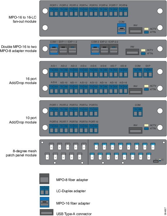
Front Panel Layout
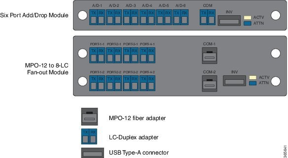
The following figure shows the front panel layout of the passive optical modules.
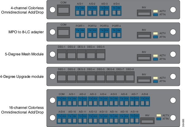
 Note |
The front panel layout for the 5-degree Mesh Connection Verification Module is the same as the 5-degree Mesh Module layout and the layout for the 4-degree Upgrade Connection Verification Module is the same as the 4-degree Upgrade Module layout. |
Note |
The MPO-8 and MPO-16 cables have a similar physical appearance. Hence, when connecting the cables to the MPO-8 or MPO-16 adapters, use only MPO-8 and MPO-16 cables to connect to their respective adapters because the optical signals will not pass through the module if a wrong cable is used. |
Note |
The front panel layout for the MPO-16 to 16-LC Fan-out Connection Verification Module is the same as the MPO-16 to 16-LC Fan-out Module layout. |
Components of Cisco ONS 15454 DWDM Passive Optical Modules
The components of Cisco ONS 15454 DWDM passive optical modules are:
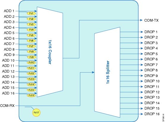
16-channel Colorless Omni-directional Add/Drop (NCS2K-MF-16AD-CFS=)
The following are the features of 16-channel colorless omni-directional add/drop passive module:
- Comprises one 1x16 splitter, one 16x1 combiner, and seventeen photodiodes arranged as shown in the following figure.
- This is a double slot module in the Cisco NCS2K-MF-1RU chassis.
- Embeds PDs for connectivity check and monitoring purposes.
- Virtual PDs are implemented by the unit on the drop ports.
- At CTC level, 33 power values are reported.
- USB connection can provide power values at PD and the manufacturing data stored in the flash memory.
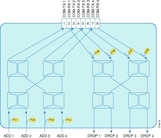
4-channel Colorless Omni-directional Add/Drop (NCS2K-MF-4X4-COFS=)
The following are the features of 4-channel colorless omni-directional add/drop passive module:
- Passive unit comprising of eight 2x2 optical couplers and eight photodiodes, arranged as shown in the following figure.
- This is a single slot module in the Cisco NCS2K-MF-1RU chassis.
- Power monitoring is present at each channel input port and at each common input port.
- Virtual PDs are implemented on the channel drop ports.
- At CTC level, 12 power values are reported.
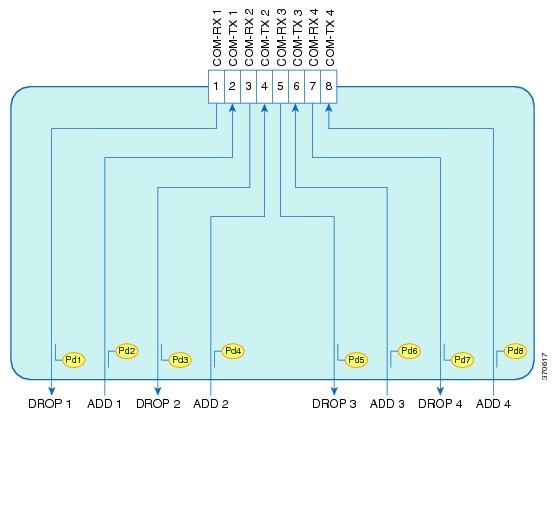
MPO to 8-LC Adapter (NCS2K-MF-MPO-8LC=)
The following are the features of the MPO to 8-LC adapter:
- Fan-out of the MPO-APC connectors to/from eight LC-PC connections.
- A total of eight photodiodes provide power monitoring of channel input and output port.
- This is a single slot module in the Cisco NCS2K-MF-1RU chassis.
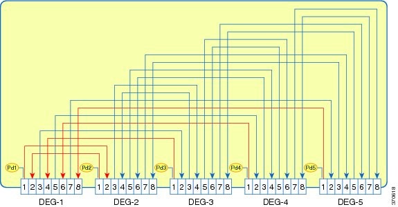
5-degree Mesh Module (NCS2K-MF-DEG-5=)
The following are the features of the 5-degree mesh module:
- The 5-degree mesh module provides interconnections among five MPO connectors. All the 40 optical paths are interconnected as reported in the following figure.
- 5 photodiodes provide power monitoring of fiber 1 of each MPO connector.
- This is a single slot module in the Cisco NCS2K-MF-1RU chassis.
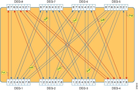
4-degree Upgrade Module (NCS2K-MF-UPG-4=)
The following are the features of the 4-degree mesh module:
-
The 4-degree upgrade module provides interconnections among 8 MPO.
-
64 optical paths are interconnected as reported in the following figure.
-
Eight photodiodes provide power monitoring of fiber 1 of each MPO connector.
-
This is a single slot module in the Cisco NCS2K-MF-1RU chassis.
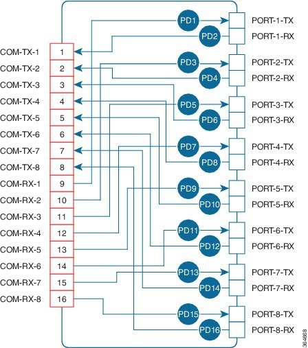
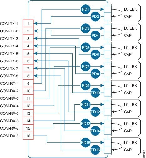
MPO-16 to 16-LC Fan-out Module (NCS2K-MF-MPO-16LC=)
The MPO-16 to 16-LC fan-out module is a double slot module with one MPO-16 connector (COM) and eight LC duplex connectors (Port-i-TX/RX). It contains 16 photodiodes to monitor the power of the channel input ports.
The MPO-16 connector is compatible with the SMR20 FS EXP and 16-AD-FS CH ports.
The features of the MPO-16 to 16-LC fan-out module are:
- It provides fan-out of the MPO-16 connector to or from the LC connections.
- It is used to interconnect the optical modules having LC connectors (TXP) with modules having MPO-16 connectors ( SMR20 FS / SMR20 FS CV and 16-AD-FS).
NCS 2000 C and L Band Combiner and Splitter (NCS2K-MF-CL-SC=)
|
Feature Name |
Release Information |
Description |
|---|---|---|
| NCS2K-MF-CL-SC | Cisco NCS 2000 Release 12.2 |
A new passive module, the C and L-band combiner and splitter, is introduced. The L-band addition for non-Raman assisted optical links requires a C and L optical combiner for expansion. The NCS2K-MF-CL-SC module allows Cisco to introduce the NCS 1010 L-band transmission system on to existing NCS 2000 deployments. |
The NCS2K-MF-CL-SC is a passive module that acts both as a combiner and a splitter.
-
As a combiner, it combines both the C and L-band channels.
-
As a splitter, it splits the composite signal into individual C and L-band channels.
The following are the features of the passive module:
-
The NCS2K-MF-CL-SC module is a single-slot (1/2 RU) rack mountable unit that fits into the NCS2K-MF-6RU shelf.
-
The module embeds photodiode for connectivity check and monitoring purposes in all the input ports (C-L RX, C-L TX). The power value readings are provided through the USB connection.
Figure 21. NCS2K-MF-CL-SC Optical Block Diagram 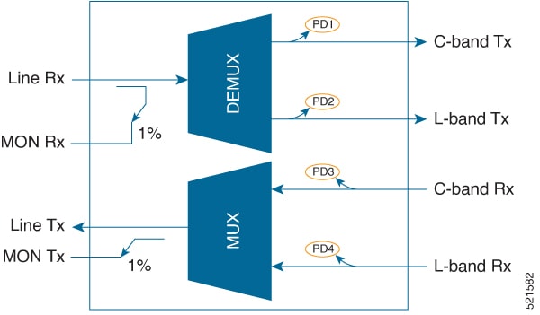
-
The passive module communicates with the different shelf controllers of the NCS 2000 platform (TNCE, TSCE, TNCS, and TNCS-O) using the following dedicated USB connections:
-
USB 2.0—Connection from ECU2, ECU-S or ECU-S-60 for the NCS2006 chassis.
-
USB 2.0—Connection from M15-ECU for NCS2015 chassis.
-
USB 3.0—When modules are inserted into the new fiber shuffles such as NCS2K-MF-6RU or MF10-6RU, the connection with the shelf controllers is provided through single USB 3.0.
-
Double MPO-16 to Two MPO-8 Adapter Module (NCS2K-MF-2MPO-ADP=)
The double MPO-16 to two MPO-8 adapter module is a single slot module with two MPO-16 connectors and four MPO-8 connectors. It contains six embedded photodiodes for connectivity check and monitoring.
The MPO-16 connectors are compatible with SMR20 FS EXP ports and MPO-8 connectors are compatible with MF-DEG-5 or MF-UPG-4 patch panel modules.
The features of the double MPO-16 to two MPO-8 adapter module are:
- It provides interconnection between one MPO-16 and two MPO-8 connectors. Two instances of MPO-16 and MPO-8 connector combination is implemented on the module with one MPO-16 connector and two MPO-8 connectors in each instance. This allows two interconnections.
- It is used to interconnect the optical modules having MPO-16 connectors (SMR20 FS / SMR20 FS CV) with modules having MPO-8 connectors (patch panel modules like NCS2K-MF-DEG-5= or NCS2K-MF-UPG-4=).
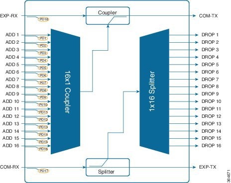
16 Port Add/Drop Module with Express Capability (NCS2K-MF-16AE-CFS=)
The 16 port add/drop module is a double slot module with 18 dual LC connectors. It contains a 16x1 combiner, a 1x16 splitter, a coupler, and a splitter.
It contains 18 embedded photodiodes for connectivity check and monitoring at all the input ports (ADD-i, EXP-RX, and COM-RX). Virtual photodiodes are implemented at the output ports (DROP-i, EXP-TX, and COM-TX).
The features of the 16 port add/drop module are:
- The module provides express traffic capability.
- It combines 16 channels from the ADD ports and the optical signal from the EXP-RX port into one signal at the COM-TX port.
- It splits the optical signal from the COM-RX port into 17 identical signals, one signal at every DROP port and one signal at the EXP-TX port.
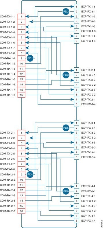
10 Port Add/Drop Module (NCS2K-MF-10AD-CFS=)
The 10 port add/drop module is a double slot module. It contains a 10x1 combiner and a 1x10 splitter.
It contains 11 embedded photodiodes for connectivity check and monitoring at all the input ports (ADD-i, and COM-RX). Virtual photodiodes are implemented at the output ports (DROP-i, and COM-TX).
The features of the 10 port add/drop module are:
- It combines 10 channels from the ADD ports into one signal at the COM-TX port.
- It splits the optical signal from the COM-RX port into 10 identical signals at the DROP ports.
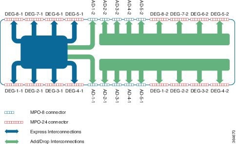
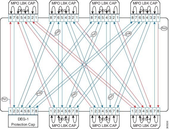
8-degree Mesh Patch Panel with 5 Add/Drop Ports (NCS2K-PPMESH8-5AD=)
The 8-degree mesh patch panel module has 16 MPO-16 connectors and 10 MPO-8 connectors. It contains 26 photodiodes for connectivity check and monitoring.
The MPO-16 connector is compatible with SMR20 FS EXP ports. The MPO-8 connector interconnects the xx SMR9 FS, MF-4X4-COFS, and the12-AD-FS or the 16-AD-FS modules.
The features of the 8-degree mesh patch panel module are:
- It provides interconnections between eight individual directions of the SMR20 FS / SMR20 FS CV module and the five stage add/drop ports.
- Eight MPO-16 connectors are used for express interconnectivity between the individual directions and also for the first add/drop stage. The rest of the connectors are used to interconnect the add/drop stages two to five.
- 10 MPO-8 connectors in the module are placed facing the add/drop stages. These connectors are used as a couple as each of them provide connectivity towards only 4 directions.
The 8-degree mesh patch panel is installed using the rack mounting bracket that is two rack units high. Each package includes one set of the following brackets. Each package includes one set of the following brackets:
- 19-inch (482.6-mm) or 23-inch (584.2-mm) reversible (two-way) mounting brackets that can be rotated to fit either rack size. These reversible brackets are used for EIA and IEC standard racks.
- ETSI brackets that are used for 600 mm x 600 mm or 600 mm x 300 mm ETSI standard racks.
Note |
The module is shipped with the mounting brackets in the 19-inch (482.6-mm) position. |
The patch panel mounting brackets can be mounted such that the patch panels project:
- 4.2, 4.9, 7.6, or 9.2 inches from the front of the EIA standard racks fixing plane (or)
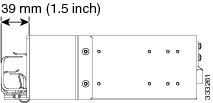
- 39 mm from the front of the ETSI standard racks fixing plane (or)
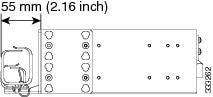
- 55 mm from the front of the IEC standard racks fixing plane
Diagram 1 in the following figure shows 4.2 inch recess location for EIA standard racks.
Diagram 2 in the following figure shows 4.9 inch recess location for EIA standard racks.
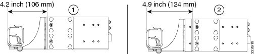
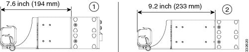
Diagram 1 in the following figure shows 7.6 inch recess location for EIA standard racks.
Diagram 2 in the following figure shows 9.2 inch recess location for EIA standard racks.
The following figure shows 39 mm recess location for ETSI standard racks.
The following figure shows 55 mm recess location for IEC standard racks.
 Caution |
Use only the fastening hardware provided with the 8-degree mesh patch panel to prevent loosening, deterioration, and electromechanical corrosion of the hardware and joined material. |
Caution |
When mounting the 8-degree mesh patch panel in a frame with a non-conductive coating (such as paint, lacquer, or enamel) use either the thread-forming screws provided with the shipping kit or remove the coating from the threads to ensure electrical continuity. |
Note |
It is recommended to configure the PPMESH8-5AD passive modules after configuring the other passive modules. If any passive modules are configured after the PPMESH8-5AD module, the snmpwalk operation ends without incrementing the error message OID. The checking of OID order must be disabled in SNMP manager to avoid this error. For example, issue the following command from net-snmp: ./snmpwalk -v2c -c public -Cc IP address .1 |
This procedure describes the steps to install the 8-degree mesh patch panel module.
Procedure
| Step 1 |
Mount the brackets on the patch panel (see the following figure):
|
||||||||
| Step 2 |
Install the patch panel on the appropriate rack equipment:
|
||||||||
| Step 3 |
Establish grounding for the patch panel:
|
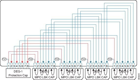
5-degree Mesh Connection Verification Module (NCS2K-MF-DEG-5-CV=)
The 5-degree mesh connection verification module is a single slot module based on the 5-degree Mesh Module (NCS2K-MF-DEG-5=). It has four MPO-8 loopback caps (NCS2K-MPO-LBK=) on DEG2, DEG3, DEG4, and DEG5 ports. DEG1 port has the usual protection cap.
The 5-degree mesh connection verification module provides connection verification capability when interconnected with the SMR20 FS CV card.
4-degree Upgrade Connection Verification Module (NCS2K-MF-UPG-4-CV=)
The 4-degree upgrade connection verification module is a single slot module based on the 4-degree Upgrade Module (NCS2K-MF-UPG-4=). It has seven MPO-8 loopback caps (NCS2K-MPO-LBK=) on ports DEG2 to DEG8. DEG1 port has the usual protection cap.
The 4-degree upgrade connection verification module provides connection verification capability when interconnected with the SMR20 FS CV card.
MPO-16 to 16-LC Fan-out Connection Verification Module (NCS2K-MF-M16LC-CV=)
The MPO-16 to 16-LC fan-out connection verification module is a double slot module based on the MPO-16 to 16-LC Fan-out Module (NCS2K-MF-MPO-16LC=). It has eight LC loopback caps (NCS2K-LC-LBK=) on all LC dual ports. The MPO-16 COM port has the usual protection cap.
The MPO-16 to 16-LC fan-out connection verification module provides connection verification capability when interconnected with the SMR20 FS CV card.
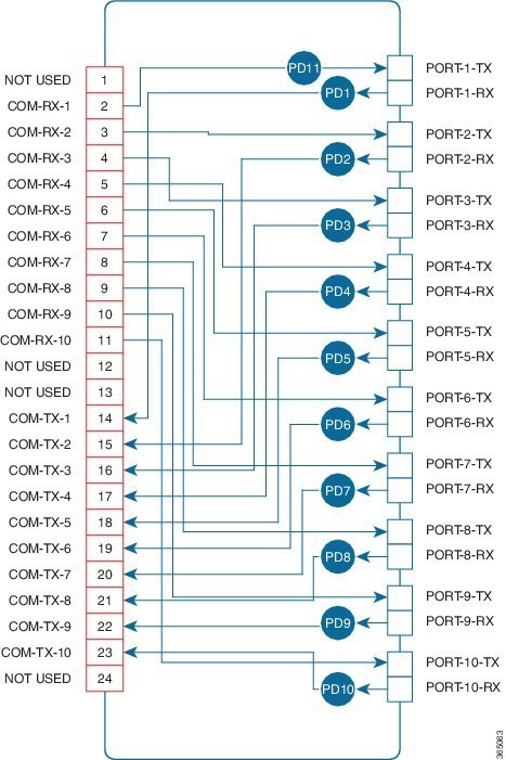
MPO-24 to 20-LC Fan-out Module (NCS2K-MF-MPO-20LC=)
The MPO-24 to 20-LC fan-out module is a double slot module with one MPO-24 connector (COM) and ten LC duplex connectors (Port-i-TX/RX). It contains 11 photodiodes to monitor the power of the channel input and output ports.
The features of the MPO-24 to 20-LC fan-out module are:
- It provides fan-out of the MPO-24 connector to or from the LC connections.
- It operates in both 1310 nm and 1550 nm wavelength ranges.
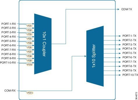
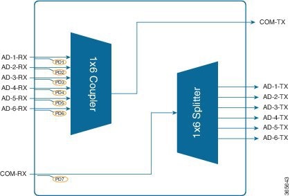
6 Port Add/Drop Module (NCS2K-MF-6AD-CFS=)
The six port add/drop module is a single slot module. It contains a 6x1 combiner and a 1x6 splitter.
It contains seven embedded photodiodes for connectivity check and monitoring at all the input ports (ADD-i-RX, and COM-RX). Virtual photodiodes are implemented at the output ports (DROP-i-TX, and COM-TX).
The features of the six port add/drop module are:
- It combines six channels from the ADD-i-RX ports into one signal at the COM-TX port.
- It splits the optical signal from the COM-RX port into six identical signals at the DROP-i-TX ports.
- It operates in the 1520 nm to 1570 nm wavelength range.
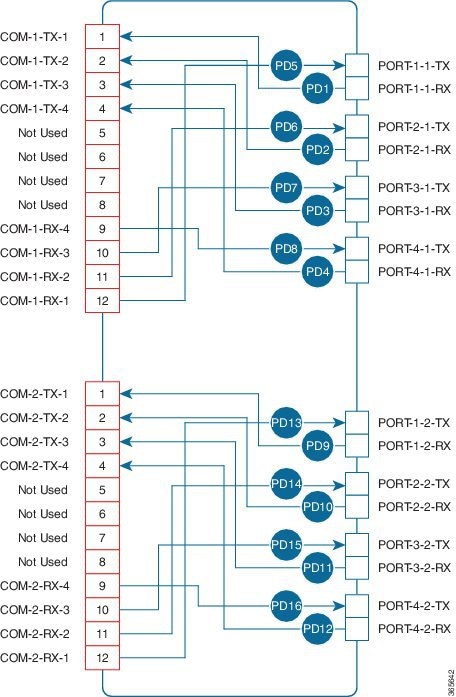
MPO-12 to 8-LC Fan-out Module (NCS2K-MF-8X10G-FO=)
The MPO-12 to 8-LC fan-out module is a double slot module with two MPO-12 connector (COM) and eight LC duplex connectors (Port-i-TX/RX). It contains 16 photodiodes to monitor the power of the channel input ports.
The features of the MPO-12 to 8-LC fan-out module are:
- It provides fan-out of the MPO-12 connectors to or from eight LC-PC connections. There are two independent fan-out sections: COM-1 to PORT-i-1-TX/RX and COM-2 to PORT-i-2-TX/RX.
- It is used as client interconnection between two QSFP+ interfaces.
- It splits 4x10G signals from the QSFP+ MPO cable into four single 10G bidirectional connections.
- It operates in two wavelength ranges: 1260 nm to 1365 nm and 1520 nm to 1570 nm.
Cisco ONS 15454 DWDM Passive Optical Modules Specifications
This section contains the environmental and mechanical specifications of the Cisco ONS 15454 DWDM passive optical modules.
Environmental Performance Specifications
The following table provides the environmental performance specifications of the Cisco ONS 15454 DWDM passive optical modules.
|
Environmental Condition |
Min |
Max |
Units |
|---|---|---|---|
|
Continuous Operative Temperature Range (OTR) |
-5 |
55 |
Celsius |
|
23 |
131 |
Fahrenheit |
|
|
Power Handling for the Optical Port |
500 |
— |
mW |
|
Max USB current consumption |
500 |
mA |
|
Mechanical Specifications
The following table provides the mechanical dimensions of the passive optical modules, fiber shuffle, loopback caps, and MPO fan-out unit.
|
Optical unit |
Description |
Physical Dimensions (mm) |
Weight (kg) |
||
|---|---|---|---|---|---|
|
Height |
Width |
Depth |
|||
|
NCS2K-MF-16AD-CFS= |
16-channel colorless omni-directional add/drop |
35 |
179 |
164 |
0.8 |
|
NCS2K-MF-4X4-COFS= |
4-channel colorless omni-directional add/drop |
17 |
179 |
164 |
0.58 |
|
NCS2K-MF-MPO-8LC= |
MPO to 8-LC adapter |
17 |
179 |
164 |
0.58 |
|
NCS2K-MF-DEG-5= |
5-degree mesh module |
17 |
179 |
160 |
0.58 |
|
NCS2K-MF-UPG-4= |
4-degree upgrade module |
17 |
179 |
160 |
0.58 |
|
NCS2K-MF-MPO-16LC= |
MPO-16 to 16-LC fan-out module |
35 |
179 |
146.5 |
0.689 |
|
NCS2K-MF-2MPO-ADP= |
Double MPO-16 to two MPO-8 adapter module |
17 |
179 |
146.5 |
0.552 |
|
NCS2K-MF-16AE-CFS= |
16 port add/drop module with express capability |
35 |
179 |
146.5 |
0.726 |
|
NCS2K-MF-10AD-CFS= |
10 port add/drop module |
35 |
179 |
146.5 |
0.697 |
|
NCS2K-PPMESH8-5AD= |
8-degree mesh patch panel with 5 add/drop ports |
87.6 |
437 |
266 |
3.020 |
|
NCS2K-MF-6RU= |
Fiber shuffle |
263.5 |
483.2 |
248 |
7.68 |
|
NCS2K-MF10-6RU= |
MPO fan-out unit |
263.5 |
483.2 |
248 |
7.52 |
|
NCS2K-MF-DEG-5-CV= |
5-degree mesh connection verification module with MPO-8 loopback caps |
17 |
179 |
215 |
0.563 |
|
NCS2K-MF-UPG-4-CV= |
4-degree upgrade connection verification module with MPO-8 loopback caps |
17 |
179 |
215 |
0.593 |
|
NCS2K-MF-M16LC-CV= |
MPO-16 to 16-LC fan-out connection verification module with LC loopback caps |
35 |
179 |
215 |
0.715 |
|
NCS2K-MPO-LBK= |
MPO-8 plug connector with eight fibers |
7.75 |
54.5 |
13.9 |
0.0047 |
|
NCS2K-LC-LBK= |
UPC LC plug dual connector with internal interconnection between two ports |
9.2 |
35 |
15 |
0.0047 |
|
NCS2K-MF-MPO-20LC= |
MPO-24 to 20-LC fan-out module |
35 |
179 |
215 |
0.659 |
|
NCS2K-MF-6AD-CFS= |
six port add/drop module |
17 |
179 |
165 |
0.7 |
|
NCS2K-MF-8X10G-FO= |
MPO-12 to 8-LC fan-out module |
35 |
179 |
165 |
1 |
Installation
This section explains how to:
Unpack and Verify the Rack Mounting Bracket and Optical Modules
The rack mounting bracket and the optical modules are shipped in separate packages. This procedure describes the steps for unpacking and verifying both the components.
Procedure
| Step 1 |
Unpack and inspect the rack mounting bracket and optical modules. The rack mounting bracket package should include these components with the quantity of the item (specified in parentheses), included in the package.
The optical module package should include the following components:
|
| Step 2 |
Compare the equipment received with the packing slip and the equipment list that customer service provided. If there are any discrepancies, notify the Customer Service Center. |
| Step 3 |
Check for external damage. Visually check all components and immediately report any shipping damage to your customer service representative. Have this information ready:
|
Install the Rack Mounting Bracket
This procedure explains how to install the rack mounting bracket to the ANSI, IEC, or ETSI standard equipment rack.
Procedure
| Step 1 |
Insert the tie-wraps on both sides of the rack mounting bracket. |
| Step 2 |
To mount the rack mounting bracket to the standard equipment rack:

 |
| Step 3 |
Insert the screws along with the lock washers and tighten them. |
Install the Optical Module
This procedure explains how to install the optical module into the rack mounting bracket.
Procedure
| Step 1 |
Install the rack mounting bracket on the equipment rack by following the steps described in the Install the Rack Mounting Bracket. |
||
| Step 2 |
Identify the slot in the rack mounting bracket to install the optical module.
|
||
| Step 3 |
Loosen the captive screws to remove the filler panel from the rack mounting bracket (see the following figure). 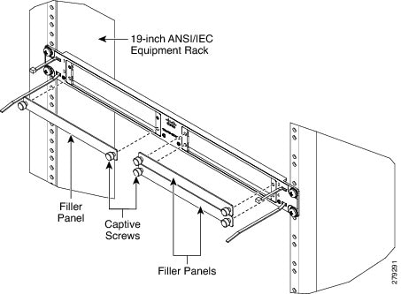 |
||
| Step 4 |
Insert the optical module into the empty slot (see the following figure). 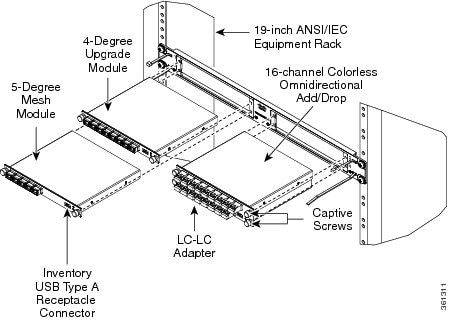 |
||
| Step 5 |
Tighten the captive screws of the optical module to fix them into the rack mounting bracket (see the following figure). 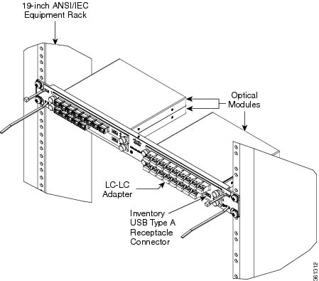 |
||
| Step 6 |
To connect the fibers as appropriate: Remove the LC or MPO dust cap from the LC-LC or MPO-MPO adapter of the optical module respectively. Route the optical patch cords with the LC or MPO connectors to the optical module. Refer to the port label description and channel identification port information of the optical module. For fibering instructions, see the Fiber-Optic Connector Cleaning and Maintenance and the Install and Route Fiber-Optic Cables. |
||
| Step 7 |
Connect the inventory USB Type A plug connector of the USB cable to the inventory USB Type A receptacle present on the optical module. To secure the USB cable and the fiber patch cords, lock it with the tie-wrap.
|
Ground Description
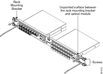
The unpainted surface between the rack mounting bracket and optical modules, ensure proper grounding of the passive optical module (see the following figure). The rack mounting bracket, the straight external brackets, and the Z-shaped external brackets are unpainted and treated with conductive finishing.
Install and Route the USB cable
This procedure explains how to install and route the USB cable into the NCS 2006 chassis.
Procedure
| Step 1 |
Align the USB connector of the USB-USB cable to the receptacle on the front panel. |
| Step 2 |
Gently push the USB connector in the USB receptacle. |
| Step 3 |
Connect the connector at the other side of the USB cable to the proper receptacle on the NCS 2006 shelf. |
| Step 4 |
Route the USB cables through the left or right side. |
Fiber-Optic Connector Cleaning and Maintenance
Connector cleaning is required to maintain the performance of fiber-optic circuits. It is important that both the LC/UPC/MPO connector at the end of the fiber-optic cable and the mating bulkhead adapter on the front panel of the optical modules are clean before the connection is made.
Warning |
Invisible laser radiation may be emitted from disconnected fibers or connectors. Do not stare into beams or view directly with optical instruments. Statement 1051 |
The following warning applies to disposal of chemicals and other materials used to clean connectors and adapters:
Warning |
Ultimate disposal of this product should be handled according to all national laws and regulations. Statement 1040 |
Before installing the fiber-optic cable, always perform the cleaning procedure for cable connectors described in the following section. Whenever possible, inspect each connector before connecting it to the mating bulkhead adapter on the front panel.
The LC/MPO bulkhead adapters on the optical modules are less likely to get dirty if they are capped when not in use. Because the procedure for a thorough cleaning of these adapters is complicated, we recommend that you use a commercially available cleaning kit and closely follow the instructions included with the kit.
Customer Supplied Cleaning Materials
The Type A fiber-optic connector cleaners (for example, CLETOP reel) are recommended to clean the cable connectors, but are not supplied with the passive optical modules.
When cleaning a paired cable connector (bulkhead mating adapter), always clean the mating adapter first.
If properly maintained (only used with clean, defect-free fiber connectors and capped when not in use), the mating adapter would not require cleaning. However, if you suspect the adapter is dirty, clean it by using the CLETOP stick swab.
Note |
For multi-fiber cable assemblies, use specific cleaning tools or materials designed for the assembly type. |
Clean the Bulkhead Mating Adapters
This procedure explains how to clean the bulkhead mating adapters.
Procedure
| Step 1 |
Read the manufacturer (cleaning cartridge) instructions to insert the cartridge cleaning tip into the mating adapter. |
||
| Step 2 |
Slide the lever on the cartridge to swipe the mating surface.
|
Clean Fiber-Optic Cable Connectors
The tools required to clean fiber-optic cable connectors are:
- Inspection microscope
- Type A fiber-optic connector cleaner (CLETOP reel)
- Optical swab
- Optical receiver cleaning stick
Procedure
| Step 1 |
Using an inspection microscope, inspect each fiber connector for dirt, cracks, or scratches. |
||||
| Step 2 |
Replace any damaged fiber connectors.
|
||||
| Step 3 |
Clean the fiber connectors with CLETOP reel: Remove the dust cap from the fiber connector. Press the lever down to open the shutter door. Each time you press the lever, you expose a clean wiping surface. Insert the connector into the CLETOP cleaning cassette slot, rotate one quarter turn, and gently swipe downwards. Use an inspection microscope to inspect each fiber connector for dirt, cracks, or scratches. If the connector is not clean, repeat Steps a to b. Insert the fiber connector into the applicable adapter or attach a dust cap to the fiber connector.
|
Install and Route Fiber-Optic Cables
Warning |
Invisible laser radiation may be emitted from disconnected fibers or connectors. Do not stare into beams or view directly with optical instruments. Statement 1051 |
Caution |
When connecting an optical fiber patch cord between the optical module and the optical card ports in the Cisco NCS, use the electrostatic discharge wristband supplied with the Cisco NCS. Plug the wristband into the ESD jack on the lower right front side of the Cisco NCS. |
Note |
Always clean all fiber connectors thoroughly before making the connection with the mating adapter. Very small particles can permanently damage the end of the mating fiber inside the optical module, which makes regular cleaning imperative. For cleaning instructions see Fiber-Optic Connector Cleaning and Maintenance. |
Note |
The optical modules feature LC/UPC/MPO bulkhead adapters. Always use fiber-optic cables equipped with the corresponding (LC/UPC/MPO) connector type. Using any other type of connector results in damage to the connector or adapter, or both. |
This procedure explains how to install and route fiber-optic cables.
Procedure
| Step 1 |
Place the LC/UPC/MPO cable connector in front of the corresponding bulkhead adapter on the front panel of the optical modules. |
| Step 2 |
Align the keyed ridge of the cable connector with the slot in the receiving adapter. |
| Step 3 |
Gently push the cable connector into the adapter until you hear a click, which indicates that the latching system is engaged. |
| Step 4 |
Route the fiber cables through the left or right side. |
What to do next
Note |
If high connection density in the optical modules (that are plugged into the same rack mounting bracket or optical modules assembled in the rack mounting bracket immediately above or below) causes difficulties to the operator in the proper handling of the optical connectors, the specific optical module has to be removed from the rack mounting bracket, fully connected with proper optical connectors, USB cable and then reassembled into the rack mounting bracket. |
Uninstalling the Module
This procedure describes the steps for removing the optical modules from the rack.
Procedure
| Step 1 |
Remove the fibers and the cable from the optical modules. |
| Step 2 |
Disconnect the inventory USB cable from the USB receptacle. |
| Step 3 |
Loosen the captive screws of the optical modules. |
| Step 4 |
Extract the optical modules from the rack mounting bracket. |
| Step 5 |
Loosen the screws of the rack mounting bracket. |
| Step 6 |
Remove the rack mounting bracket from the equipment rack. |
What to do next
Note |
If it is not possible to remove the optical connectors due to high connection density in step 1, unplug the optical module as per step 3 and step 4. Now, the optical connectors and the USB cable can be disconnected easily. |
Related Documentation
Use the Installing the Cisco ONS 15454 DWDM passive optical modules document in conjunction with the following referenced publications:
- Cisco ONS 15454 DWDM Control Card and Node Configuration Guide
- Cisco ONS 15454 DWDM Line Card Configuration Guide
- Cisco ONS 15454 DWDM Network Configuration Guide
- Cisco ONS 15454 DWDM Troubleshooting Guide
Visit the End-of-Life and End-of-Sale Notices page for EOL and EOS announcements.
Obtaining Documentation and Submitting a Service Request
For information on obtaining documentation, submitting a service request, and gathering additional information, see the monthly What's New in Cisco Product Documentation, which also lists all new and revised Cisco technical documentation, at:
http://www.cisco.com/c/en/us/td/docs/general/whatsnew/whatsnew.html
Subscribe to the What’s New in Cisco Product Documentation as a Really Simple Syndication (RSS) feed and set content to be delivered directly to your desktop using a reader application. The RSS feeds are a free service and Cisco currently supports RSS Version 2.0.
 Feedback