System Engineering
This chapter provides the basic planning and engineering information required to configure an ONS 15454 node for DWDM deployment.
The following topics are covered in this chapter:
5.1 Client Interfaces
Table 5-1 lists all DWDM cards and their assigned class.
|
|
|
|
|
|
|
|---|---|---|---|---|---|
15454-O48E-1-xx.x |
2.5 Gbps |
Client 1+1 |
OC-48 (ANSI) |
OC48 ELR/STM16EH 100 GHz -15xx.xxnm |
G |
15454E-EL16HSxx.xx (ETSI) |
STM16 (ETSI) |
||||
15454-MRP-L1-xx.x (ANSI Fiber Switched) 15454-MRP-I-xx.x (ETSI Fiber Switched) 15454-MR-L1-xx.x (ANSI) 15454E-MR-1-xx.x (ETSI) |
2.5G MR TXP w/FEC1 (ISC-1 Not Supported) |
Client 1+1 |
TXPP_MR_2.5G TXP_MR_2.5G |
2.5-Gbps Multirate Transponder-Protected 100-GHz-Tunable xx.xx-xx.xx 2.5-Gbps Multirate Transponder 100-GHz-Tunable xx.xx-xx.xx |
D/E/F |
2.5G MR TXP w/o FEC |
Client 1+1 |
||||
2.5G MR TXP 2R2 Mode |
Client 1+1 |
||||
15454-192L-1-xx.x (ANSI) 15454E-64L-1-xx.x (ETSI) |
10-Gbps LR3 ITU-T |
Client 1+1 |
OC-192(ANSI) STM-64 (ETSI) |
OC-192 LR/STM64 LH ITU 15xx.xx |
C |
15454 10T-L1-xx.xx (ANSI) 15454E 10T-xx.xx (ETSI) |
10G MR TXP w/FEC 10G MR TXP w/o FEC |
Client 1+1 Y-Cable |
TXP_MR_10G |
10-Gbps Transponder-100-GHz - Tunable xx.xx-xx.xx |
A/B/C |
15454-10M-L1-xx.xx (ANSI) 15454E-10M-xx.xx (ETSI) |
4x2.5-Gbps MXP w/FEC 4x2.5-Gbps MXP w/o FEC |
Client 1+1 Y-Cable |
MXP_2.5G_10G |
2.5-Gbps-10-Gbps Muxponder-100-GHz- Tunable xx.xx-xx.xx |
A/B/C |
15454-DMP-L1-xx.xx (ANSI Fiber-switched) 15454-DMP-1-xx.x (ETSI Fiber Switched) 15454-DM-L1-xx.x (ANSI) 15454-DM-1-xx.x (ETSI) |
2.5G Data MXP w/o FEC |
Client 1+1 Y-Cable Fiber-Switched |
MXPP_MR_2.5G MXP_MR_2.5G |
2.5-Gbps Multirate Muxponder-Protected- 100-GHz-Tunable 15xx.xx-15yy.yy 2.5-Gbps Multirate Muxponder - 100-GHz-Tunable 15xx.xx-15yy.yy |
E |
15454-10E-L1-xx.xx (ANSI) 15454E-10E-1-xx.xx (ETSI) |
10G Enh MR TXP w/ FEC 10G Enh MR TXP w/ FEC 10G Enh MR TXP w/o FEC |
Client 1+1 Y-Cable |
TXP_MR_10E |
10-Gbps Transponder 100-GHz-Enhanced- Tunable xx.xx-xx.xx |
A/C/I |
15454-10ME-xx.x (ANSI) 15454E-10ME-xx.x (ETSI) |
4x2.5-Gbps Enh MXP w/ EFEC4 4x2.5-Gbps Enh MXP w/ FEC |
Client 1+1 Y-Cable |
MXP_2.5G_10E |
10-Gbps Muxponder - 100-GHz-Enhanced FEC -Tunable xx.x-xx.x |
A/C/I |
15454-10E-L1-C= |
10G Enh MR TXP w/ FEC 10G Enh MR TXP w/ FEC 10G Enh MR TXP w/o FEC |
Client 1+1 Y-Cable |
TXP_MR_10E |
10-Gbps Transponder Full C-Band Tunable |
A/C/I |
15454-10E-L1-L= |
10-Gbps Transponder Full L-Band Tunable |
||||
15454-10ME-L1-C= |
10G Enh MR MXP w/ EFEC 10G Enh MR MXP w/ FEC 10G Enh MR MXP w/o FEC |
MXP_2.5G_10E |
10-Gbps Muxponder Full C-Band Tunable |
||
15454-10ME-L1-L= |
10-Gbps Muxponder Full L-Band Tunable |
||||
15454-10DME-C= |
10G Enh DATA MXP w/ EFEC 10G Enh DATA MXP w/ FEC 10G Enh DATA MXP w/o FEC |
MXP_MR_10DME |
10-Gbps Data Muxponder Full C-Band Tunable |
||
15454-10DME-L= |
10-Gbps Data Muxponder Full L-Band Tunable |
||||
15454-GBIC-xx.x (ANSI) 15454E-GBIC-xx.x (ETSI) |
Client 1+1 |
WDM GBIC xx.x |
GBIC xx.x WDM 100GHz |
G |
|
15530-ITU2-xx10 (w/splitter) 15530-ITU2-xx20 (no splitter) |
10Gbps Aggregation (w/splitter) 10Gbps Aggregation |
Client 1+1 Fiber-switched/Splitter |
ONS 15530 Ch x 10-Gbps ITU Trunk Card MU w/ Splitter ONS 15530 Ch x 10-Gbps ITU Trunk Card MU w/o Splitter |
ONS 15530 10-Gbps ITU Trunk Card with splitter ONS 15530 10-Gbps ITU Trunk Card without splitter |
C |
15530 -ITU3-xx10 (w/splitter) 15530-ITU3-xx20 (no splitter) |
2.5 Gbps Aggregation (w/ splitter) 2.5 Gbps Aggregation |
Client 1+1 Fiber-switched/Splitter |
15530-ITU3-xx10 15530 ITU3-xx 20 |
ONS 15530 Ch x/y 2.5-Gbps ITU Trunk Card MU w/ Splitter ONS 15530 Ch x/y 2.5-Gbps ITU Trunk Card MU w/o Splitter |
J |
15530-TSP1-xx11 (MM7 w/splitter) 15530-TSP1-xx12 (SM8 w/splitter) 15530-TSP1-xx21 (MM, no splitter) 15530-TSP1-xx22 (SM, no splitter) |
MR MM Transponder (w/ splitter) MR SM Transponder (w/ splitter) MR MM Transponder MR SM Transponder |
Client 1+1 Y-Cable Fiber-switched/ Splitter |
15530-TSP1-xx11 15530-TSP1-xx12 15530-TSP1-xx21 15530-TSP1-xx22 |
ONS 15530 Transponder Ch x/y - 1310 nm MM SC w/splitter ONS 15530 Transponder Ch x/y - 1310 nm SM SC w/splitter ONS 15530 Transponder Ch x/y - 1310 nm MM SC w/o splitter ONS 15530 Transponder Ch x/y - 1310 nm SM SC w/o splitter |
J |
15530-MSMP-xx12 (w/ splitter) 15530-MSMP-xx22 (no splitter) |
Data Muxponder (w/splitter) Data Muxponder |
Client 1+1 Fiber-switched/splitter |
15530 MSMP-xx12 15530 MSMP-xx22 |
MR Data Muxponder (w/ splitter) MR Data Muxponder (w/o splitter) |
J |
1 FEC: Forward Error Correction 2 2R: reshape and regenerate 3 LR: Long Range 4 EFEC: Enhanced FEC 5 WDM: Wavelength division multiplexing 6 GBIC: Gigabit Interface Converter 7 MM: Multimode 8 SM: Single mode |
Client interfaces (cards) have been grouped in ten classes (Class A through Class J). All client interfaces supported by DWDM can be specified in terms of their ISO-BER curve.
The operative area of an interface is defined on a two-dimensional Cartesian plane where the X axis is the optical signal-to-noise ratio (OSNR) value [in dB] and the Y axis is the power value [in dBm], as shown in Figure 5-1.
The limits to the operative area are three lines that result from a simple approximation of an ISO-BER line. The original ISO-BER line has two points, OSNR Limited (OL) and Power Limited (PL), that define the two main borders of the simplified working area. The two main borders are "OSNR Limited" and "Power Limited." OL and OP are defined by two sets of coordinates, namely OLOSNR/OLPower and PLOSNR/PLPower, whose initial values are defined in Table 5-2, Table 5-3, and Table 5-4.
Figure 5-1 Client Interface ISO BER Curve and Rectangle Definition for Specifying Performance
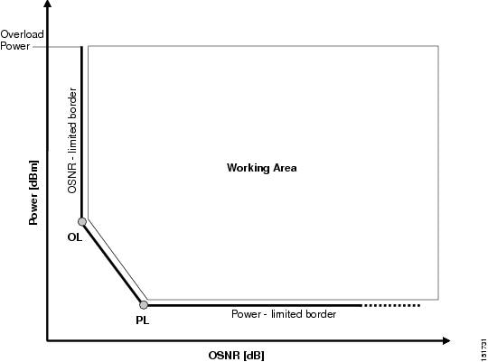
The upper limit of the "OSNR limited" border is the interface power overload, which also draws an upper limit to the working area. Theoretically, there is no upper limit to the OSNR value, but physical constraints limit this value to 35 to 40 dB.
5.2 System Optical Performance
This section discusses the optical performance parameters of a Cisco ONS 15454 DWDM system.
5.2.1 Maximum Number of Nodes
The Network Wizard in the Cisco MetroPlanner tool allows you to create a ring or a linear topology with a maximum of 60 locations. Up to 20 of these 60 locations can be equipped with optical amplifier cards (OPT-PRE and/or OPT-BST) and optical service channel cards (OSCM and/or OSC-CSM cards). Up to 16 of those 20 locations can be equipped with optical add/drop multiplexer (OADM) cards.
The entire network cannot include more than 40 amplifiers in each direction [clockwise(CW)/counter clockwise(CCW)], which relates to the 20 locations that can be equipped with optical amplifier cards and optical service channel cards.
Before 3R regeneration occurs, individual optical connections cannot include more than 30 amplifiers per direction (CW/CCW), which relates to the number of OADM nodes you can have in the network, assuming that there are a maximum of two optical amplifiers in the same node.
5.2.2 Optical Performance (OSNR Limited)
A network configuration, whether ring or linear, is created by a general combination of spans and nodes with unequal losses. Cisco MetroPlanner requires that the design of a network (in terms of amplifier and OADM card placement) must satisfy the traffic demand between the nodes. This section contains optical performance information from a limited number of reference cases characterized by configurations with equal span and node losses.
The optical performance examples provided in the "C-Band Optical Performance" section and the "L-Band Optical Performance" section are calculated for the worst channel path that can be provisioned with regard to the number of amplified nodes multiplied by the span loss (assuming equal spans and node losses in a link). For example, saying that a referenced optical performance is 5x20 dB means that the longest channel path on a ring can pass through five amplified nodes with a maximum of 20 dB loss for each span.

Note ![]() The span losses specified in this section are end-of-life values including margins for cable aging and repairs.
The span losses specified in this section are end-of-life values including margins for cable aging and repairs.
Note ![]() The optical performance examples are given for the Metro Core applications only.
The optical performance examples are given for the Metro Core applications only.
5.2.3 C-Band Optical Performance
Table 5-5 details the target system performance of an ONS 15454 DWDM C-band system.
|
|
|
|
|
|---|---|---|---|
32 |
SMF-281 E-LEAF2 TW-RS3 |
Ring Linear Linear without OADM |
Hub Active OADM Passive OADM ROADM Terminal Line OSC regeneration |
16 |
SMF-28 |
Ring Linear Linear without OADM |
Hub Active OADM Passive OADM ROADM Terminal Line OSC regeneration |
8 |
SMF-28 |
Linear without OADM |
Terminal Line |
1 SMF-28 = single-mode fiber 28 2 E-LEAF = enhanced large effective area fiber 3 TW-RS = TrueWave reduced slope fiber |
For a description of rings and linear configurations with fixed OADM nodes and without OADM nodes, refer to the "Network Reference" chapter in the Cisco ONS 15454 DWDM Reference Manual. For optical performance information for ROADM rings and single-span networks, also refer to the "Network Reference" chapter in the Cisco ONS 15454 DWDM Reference Manual.
5.2.3.1 Optical Performance for Rings and Linear Networks with OADM Nodes
The following tables provide optical performance estimates for open and closed ONS 15454 rings and linear networks with OADM nodes.
Table 5-6 shows the optical performance for 32-channel networks using SMF fiber. Span losses shown in the table assume:
•![]() OADM nodes have a loss of 16 dB and equal span losses.
OADM nodes have a loss of 16 dB and equal span losses.
•![]() The dispersion compensation unit (DCU) loss is 9 dB.
The dispersion compensation unit (DCU) loss is 9 dB.
•![]() OPT-PRE and OPT-BST/OPT-BST-E amplifiers are installed in all nodes.
OPT-PRE and OPT-BST/OPT-BST-E amplifiers are installed in all nodes.
•![]() The OPT-PRE amplifier switches to control power whenever the span loss is higher than 27 dB.
The OPT-PRE amplifier switches to control power whenever the span loss is higher than 27 dB.
|
|
|
|
||||||||
|---|---|---|---|---|---|---|---|---|---|---|
|
|
|
|
|
|
|
|
|
|
|
|
1 |
35 dB |
25 dB |
25 dB |
37 dB |
37 dB |
33 dB |
30 dB |
32 dB |
34 dB |
30 dB |
2 |
29 dB |
21 dB |
20 dB |
30 dB |
31 dB |
27 dB |
25 dB |
26 dB |
28 dB |
25 dB |
3 |
26 dB |
17 dB |
15 dB |
28 dB |
29 dB |
25 dB |
23 dB |
24 dB |
26 dB |
23 dB |
4 |
24 dB |
— |
— |
25 dB |
26 dB |
23 dB |
20 dB |
22 dB |
24 dB |
20 dB |
5 |
23 dB |
— |
— |
24 dB |
25 dB |
22 dB |
16 dB |
20 dB |
23 dB |
16 dB |
6 |
21 dB |
— |
— |
23 dB |
24 dB |
19 dB |
— |
17 dB |
21 dB |
— |
7 |
201 dB |
— |
— |
22 dB |
23 dB |
16 dB |
— |
— |
19 dB |
— |
1 0.5 dB of OSNR impairment recovered by FEC margin @ BER > 10-6 |
Table 5-7 shows the optical performance for 16-channel networks using SMF fiber. Span loss values assume the following:
•![]() OADM nodes have a loss of 16 dB and equal span losses.
OADM nodes have a loss of 16 dB and equal span losses.
•![]() The DCU loss is 9 dB.
The DCU loss is 9 dB.
•![]() All nodes have OPT-PRE and OPT-BST/OPT-BST-E amplifiers installed.
All nodes have OPT-PRE and OPT-BST/OPT-BST-E amplifiers installed.
•![]() The OPT-PRE amplifier switches to control power whenever the span loss is higher than 27 dB.
The OPT-PRE amplifier switches to control power whenever the span loss is higher than 27 dB.
Table 5-8 shows the optical performance for 32-channel networks using TW-RS fiber. Span loss values assume the following:
•![]() OADM nodes have a loss of 16 dB and equal span losses.
OADM nodes have a loss of 16 dB and equal span losses.
•![]() The DCU is 550 ps with 4 dB loss.
The DCU is 550 ps with 4 dB loss.
•![]() All nodes have OPT-PRE and OPT-BST/OPT-BST-E amplifiers installed.
All nodes have OPT-PRE and OPT-BST/OPT-BST-E amplifiers installed.
•![]() The OPT-PRE amplifier switches to control power whenever the span loss is higher than 27 dB.
The OPT-PRE amplifier switches to control power whenever the span loss is higher than 27 dB.
Table 5-9 shows the optical performance for 32-channel networks using E-LEAF fiber. Span loss values assume the following:
•![]() OADM nodes have a loss of 16 dB and equal span losses.
OADM nodes have a loss of 16 dB and equal span losses.
•![]() The DCU is 550 ps with 4 dB loss.
The DCU is 550 ps with 4 dB loss.
•![]() All nodes have OPT-PRE and OPT-BST/OPT-BST-E amplifiers installed.
All nodes have OPT-PRE and OPT-BST/OPT-BST-E amplifiers installed.
•![]() The OPT-PRE amplifier switches to control power whenever the span loss is higher than 27 dB.
The OPT-PRE amplifier switches to control power whenever the span loss is higher than 27 dB.
5.2.3.2 Optical Performance for Linear Networks Without OADM Nodes
The following tables list the reference optical performances for linear networks without OADM nodes.
Table 5-10 shows the optical performance for 32-channel linear networks using SMF fiber. Span loss values assume the following:
•![]() No OADM nodes are installed and span losses are equal.
No OADM nodes are installed and span losses are equal.
•![]() The DCU loss is 9 dB.
The DCU loss is 9 dB.
•![]() Only OPT-PRE amplifiers are installed.
Only OPT-PRE amplifiers are installed.
Table 5-11 shows the optical performance for 32-channel linear networks using TW-RS fiber. Span loss values assume the following:
•![]() No OADM nodes are installed and span losses are equal.
No OADM nodes are installed and span losses are equal.
•![]() The DCU is 550 ps with 4 dB loss.
The DCU is 550 ps with 4 dB loss.
•![]() Only OPT-PRE amplifiers are installed.
Only OPT-PRE amplifiers are installed.
Table 5-12 shows the optical performance for 32-channel linear networks using E-LEAF fiber. Span loss values assume the following:
•![]() No OADM nodes are installed and span losses are equal.
No OADM nodes are installed and span losses are equal.
•![]() The DCU is 550 ps with 4 dB loss.
The DCU is 550 ps with 4 dB loss.
•![]() Only OPT-PRE amplifiers are installed.
Only OPT-PRE amplifiers are installed.
Table 5-13 shows the optical performance for 16-channel linear networks using SMF fiber. Span loss values assume the following:
•![]() No OADM nodes are installed and span losses are equal.
No OADM nodes are installed and span losses are equal.
•![]() The DCU loss is 9 dB.
The DCU loss is 9 dB.
•![]() Only OPT-PRE amplifiers are installed.
Only OPT-PRE amplifiers are installed.
•![]() The minimum channel power is 4 dBm.
The minimum channel power is 4 dBm.
•![]() Wavelengths are picked up without any restriction from Bands 4 and 5 (1542.14 to 1545.51 nm).
Wavelengths are picked up without any restriction from Bands 4 and 5 (1542.14 to 1545.51 nm).
Table 5-14 shows the optical performance for 8-channel linear networks with 8 dBm per channel using SMF fiber. Span loss values assume the following:
•![]() No OADM nodes are installed and span losses are equal.
No OADM nodes are installed and span losses are equal.
•![]() The DCU loss is 9 dB.
The DCU loss is 9 dB.
•![]() Only OPT-PRE amplifiers are installed.
Only OPT-PRE amplifiers are installed.
5.2.3.3 Optical Performance for ROADM Rings and Linear Networks
The following tables list the reference optical performances for ROADM rings and linear networks.
Table 5-15 shows the optical performance for 32-channel linear or ring networks using SMF fiber with only ROADM nodes installed. Span loss values assume the following:
•![]() All nodes in the ring or linear network are ROADM with equal span losses.
All nodes in the ring or linear network are ROADM with equal span losses.
•![]() The DCU loss is 9 dB.
The DCU loss is 9 dB.
•![]() OPT-PRE and OPT-BST/OPT-BST-E amplifiers are installed.
OPT-PRE and OPT-BST/OPT-BST-E amplifiers are installed.
|
|
|
|
||||||||
|---|---|---|---|---|---|---|---|---|---|---|
|
|
|
|
|
|
|
|
|
|
|
|
1 |
35 dB |
25 dB |
25 dB |
36 dB |
37 dB |
33 dB |
30 dB |
32 dB |
34 dB |
— |
2 |
30 dB |
21 dB |
20 dB |
32 dB |
34 dB |
28 dB |
25 dB |
26 dB |
29 dB |
— |
3 |
28 dB |
18 dB |
17 dB |
30 dB |
32 dB |
26 dB |
23 dB |
24 dB |
27 dB |
— |
4 |
26 dB |
— |
— |
28 dB |
30 dB |
24 dB |
21 dB |
22 dB |
25 dB |
— |
5 |
25 dB |
— |
— |
27 dB |
29 dB |
23 dB |
20 dB |
20 dB |
23 dB |
— |
6 |
24 dB |
— |
— |
26 dB |
28 dB |
22 dB |
18 dB |
19 dB |
22 dB |
— |
7 |
23 dB |
— |
— |
25 dB |
27 dB |
21 dB |
14 dB |
17 dB |
20 dB |
— |
8 |
22 dB |
— |
— |
24 dB |
26 dB |
20 dB |
— |
— |
18 dB |
— |
9 |
21 dB |
— |
— |
23 dB |
25 dB |
19 dB |
— |
— |
— |
— |
10 |
21 dB |
— |
— |
23 dB |
25 dB |
18 dB |
— |
— |
— |
— |
11 |
181 dB |
— |
— |
22 dB |
24 dB |
17 dB |
— |
— |
— |
— |
12 |
171 dB |
— |
— |
21 dB |
24 dB |
15 dB |
— |
— |
— |
— |
13 |
151 dB |
— |
— |
21 dB |
23 dB |
— |
— |
— |
— |
— |
14 |
— |
— |
— |
20 dB |
23 dB |
— |
— |
— |
— |
— |
15 |
— |
— |
— |
20 dB |
22 dB |
— |
— |
— |
— |
— |
1 If the number of boosters is greater than 10 and power per channel is = to +1 dBm. |
Table 5-16 shows the optical performance for 32-channel linear or ring network with ROADM and OADM nodes using SMF fiber. Span loss values assume the following:
•![]() All nodes in the ring or linear network are ROADM or OADM.
All nodes in the ring or linear network are ROADM or OADM.
•![]() OPT-PRE and OPT-BST/OPT-BST-E amplifiers are installed.
OPT-PRE and OPT-BST/OPT-BST-E amplifiers are installed.
•![]() Span losses are equal.
Span losses are equal.
|
|
|
|
||||||||
|---|---|---|---|---|---|---|---|---|---|---|
|
|
|
|
|
|
|
|
|
|
|
|
1 |
30 dB |
23 dB |
24 dB |
31 dB |
34 dB |
31 dB |
28 dB |
29 dB |
30 dB |
28 dB |
2 |
26 dB |
19 dB |
19 dB |
27 dB |
27 dB |
26 dB |
23 dB |
26 dB |
27 dB |
23 dB |
3 |
23 dB |
— |
— |
25 dB |
26 dB |
23 dB |
21 dB |
23 dB |
24 dB |
21 dB |
4 |
21 dB |
— |
— |
23 dB |
24 dB |
22 dB |
18 dB |
21 dB |
22 dB |
18 dB |
5 |
20 dB |
— |
— |
22 dB |
23 dB |
20 dB |
13 dB |
20 dB |
21 dB |
13 dB |
6 |
17 dB |
— |
— |
19 dB |
22 dB |
18 dB |
— |
17 dB |
18 dB |
— |
7 |
151 dB |
— |
— |
17 dB |
21 dB |
16 dB |
— |
151 |
16 dB |
— |
1 0.5 dB of OSNR impairment recovered by FEC margin @ BER>10-6 |
The following tables show the pass/fail criteria for eight and sixteen ROADM nodes.
Table 5-17 shows the pass/fail criteria for eight ROADM nodes (seven spans) required for any-to-any node circuit reconfigurations:
•![]() All nodes in the ring are ROADM.
All nodes in the ring are ROADM.
•![]() Span losses are equal.
Span losses are equal.
Table 5-18 shows the pass/fail criteria for 16 ROADM nodes (15 spans) required for any-to-any node circuit reconfigurations.
•![]() All nodes in the ring are ROADM.
All nodes in the ring are ROADM.
•![]() Span losses are equal.
Span losses are equal.
|
|
|
|
|
||||||||
|---|---|---|---|---|---|---|---|---|---|---|---|
|
|
|
|
|
|
|
|
|
|
|
||
1 |
OPT-PRE only |
<151 |
<151 |
<151 |
Yes |
Yes |
<151 |
<151 |
<151 |
<151 |
— |
2 |
OPT-PRE only |
<151 |
<151 |
<151 |
Yes |
Yes |
<151 |
<151 |
<151 |
<151 |
— |
3 |
OPT-PRE only |
<151 |
<151 |
<151 |
Yes |
Yes |
<151 |
<151 |
<151 |
<151 |
— |
4 |
OPT-PRE only |
<151 |
<151 |
<151 |
Yes |
Yes |
<151 |
<151 |
<151 |
<151 |
— |
5 |
OPT-PRE only |
<151 |
<151 |
<151 |
Yes |
Yes |
<151 |
<151 |
<151 |
<151 |
— |
6 |
OPT-PRE only |
<151 |
<151 |
<151 |
Yes |
Yes |
<151 |
<151 |
<151 |
<151 |
— |
7 |
OPT-PRE and OPT-BST/ |
<151 |
<151 |
<151 |
Yes |
Yes |
<151 |
<151 |
<151 |
<151 |
— |
8 |
OPT-PRE and OPT-BST/ |
<151 |
<151 |
<151 |
Yes |
Yes |
<151 |
<151 |
<151 |
<151 |
— |
9 |
OPT-PRE and OPT-BST/ |
<151 |
<151 |
<151 |
Yes |
Yes |
<151 |
<151 |
<151 |
<151 |
— |
10 |
OPT-PRE and OPT-BST/ |
<151 |
<151 |
<151 |
Yes |
Yes |
<151 |
<151 |
<151 |
<151 |
— |
11 |
OPT-PRE and OPT-BST/ |
<151 |
<151 |
<151 |
Yes |
Yes |
<151 |
<151 |
<151 |
<151 |
— |
12 |
OPT-PRE and OPT-BST/ |
<151 |
<151 |
<151 |
Yes |
Yes |
<151 |
<151 |
<151 |
<151 |
— |
13 |
OPT-PRE and OPT-BST/ |
<151 |
<151 |
<151 |
Yes |
Yes |
<151 |
<151 |
<151 |
<151 |
— |
14 |
OPT-PRE and OPT-BST/ |
<151 |
<151 |
<151 |
Yes |
Yes |
<151 |
<151 |
<151 |
<151 |
— |
15 |
OPT-PRE and OPT-BST/ |
<151 |
<151 |
<151 |
Yes |
Yes |
<151 |
<151 |
<151 |
<151 |
— |
1 Cisco MetroPlanner calculates the maximum ring circumference and number of nodes that can be supported. |
5.2.3.4 Optical Performance for Single-Span Networks
Table 5-19 lists the span loss for a single-span link configuration with eight channels. The optical performance for this special configuration is given only for Classes A and C. This configuration assumes a maximum channel capacity of eight channels (8-dBm nominal channel power) used without any restrictions on the 32 available channels.
Table 5-20 lists the span loss for a single-span link configuration with 16 channels. The optical performance for this special configuration is given only for Class A and Class C. This configuration assumes a maximum channel capacity of 16 channels (5-dBm nominal channel power) used without any restrictions on the 32 available channels.
Table 5-21 lists the span loss for a single-span link configuration with AD-1C-x.xx cards, OPT-PRE amplifiers, and OPT-BST/OPT-BST-E amplifiers. The single-span link with a flexible channel count is used both for transmitting and receiving. If dispersion compensation is required, a DCU can be used with an OPT-PRE amplifier. The optical performance for this special configuration is given for Classes A through G (8-dBm nominal channel power) used without any restrictions on the 32 available channels.
|
|
|
|
|
|||||
|---|---|---|---|---|---|---|---|---|
|
|
|
|
|
|
|
|
||
With OSCM cards1 |
1 |
37 dB |
31 dB |
31 dB |
37 dB |
37 dB |
37 dB |
37 dB |
Hybrid with OSC-CSM cards2 |
1 |
35 dB |
31 dB |
31 dB |
35 dB |
35 dB |
35 dB |
35 dB |
1 OSCM sensitivity limits the performance to 37 dB. 2 OSC-CSM sensitivity limits the performance to 35 dB when it replaces the OSCM. |
Table 5-22 lists the span loss for a single-span link configuration with one channel and OPT-BST/OPT-BST-E amplifiers. The optical performance for this special configuration is given for Classes A through G. Classes A, B, and C use 8-dBm nominal channel power. Classes D, E, F, and G use 12-dBm nominal channel power. There are no restriction on the 32 available channels. That is, a line card, transponder, or muxponder wavelength can be extracted from the 32 available wavelengths. Also, the optical service channel is not required.
Table 5-23 lists the span loss for a single-span link configuration with one channel, OPT-BST/OPT-BST-E amplifiers, OPT-PRE amplifiers, and ONS 15216 FlexLayer filters. ONS 15216 FlexLayer filters are used instead of the AD-1C-xx.x cards to reduce equipment costs and increase the span length, since the optical service channel is not necessary. The optical performance for this special configuration is given for Classes A through G. Classes A, B, and C use 8-dBm nominal channel power. Classes D, E, F, and G use 12-dBm nominal channel power. There are no restriction on the first 16 available wavelengths (from 1530.33 to 1544.53 nm).
5.2.4 L-Band Optical Performance
Table 5-24 details the target system performance for an ONS 15454 DWDM L-band system.
|
|
|
|
|
|---|---|---|---|
32 |
SMF-28 DS1 |
Ring Linear Linear without ROADM |
Hub Terminal ROADM Line OSC regeneration |
1 DS = Dispersion Shifted fiber |
5.2.4.1 Optical Performance for Linear Networks Without ROADM Nodes
Table 5-25 shows the optical performance for 32-channel linear networks using SMF fiber. Span loss values assume the following:
•![]() No ROADM nodes are installed
No ROADM nodes are installed
•![]() Only OPT-AMP-L amplifiers are installed
Only OPT-AMP-L amplifiers are installed
•![]() Span losses are equal
Span losses are equal
Table 5-26 shows the optical performance for 32-channel linear networks using DS fiber. Span loss values assume the following:
•![]() No ROADM nodes are installed
No ROADM nodes are installed
•![]() Only OPT-AMP-L amplifiers are installed
Only OPT-AMP-L amplifiers are installed
•![]() Span losses are equal
Span losses are equal
5.2.4.2 Optical Performance for ROADM Rings and Linear Networks
Table 5-27 shows the optical performance for a 32-channel linear or ring network using SMF fiber with only ROADM nodes installed. Span loss values assume the following:
•![]() All nodes in the ring or linear network are ROADM
All nodes in the ring or linear network are ROADM
•![]() OPT-AMP-L and OPT-BST-L amplifiers are installed
OPT-AMP-L and OPT-BST-L amplifiers are installed
•![]() Span losses are equal
Span losses are equal
Table 5-28 shows the optical performance for a 32-channel linear or ring network with ROADM nodes using DS fiber. Span loss values assume the following:
•![]() All nodes in the ring or linear network are ROADM
All nodes in the ring or linear network are ROADM
•![]() OPT-AMP-L and OPT-BST-L amplifiers are installed
OPT-AMP-L and OPT-BST-L amplifiers are installed
•![]() Span losses are equal
Span losses are equal
 Feedback