Table Of Contents
Web Planning and Reporting Clients
Network Performance Data in the Database
Overview
Cisco WAN Access Performance Management System (Cisco WAPMS) is a comprehensive wide area network (WAN) service-level management system from Cisco Systems. The system integrates WAN access functionality with end-to-end performance monitoring, troubleshooting, traffic capture, and planning and reporting. It is designed to monitor traffic on networks using statistically multiplexed technologies such as Frame Relay, ATM, IP/Internet, and private line (HDLC/PPP).
With Cisco WAPMS, WAN service providers and subscribers can simultaneously view information that measures service levels and identifies potential problem areas before they affect network performance. Factors that affect network performance—the telecommunication company's transmission lines, the provider's WAN services, and the subscriber's network equipment, applications, and usage levels—are analyzed from a conveniently located client. Armed with this information, both providers and subscribers can use the system to take pro-active or corrective steps to address network problems and to plan for long-term WAN deployments.
Topics in this chapter include:
•
"System Architecture"—Cisco WAPMS system architecture components
•
•
System Architecture
A Cisco WAPMS system includes three types of components:
•
•
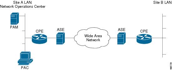
Figure 1-1 illustrates the location of these three components relative to the WAN, the subscriber's WAN equipment, customer premises equipment (CPE), and site local area networks.
Figure 1-1 Cisco WAPMS System Components
ASEs
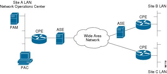
ASEs are hardware devices in the network whose embedded Cisco WAPMS agent software collects network performance data for detailed analysis by the server and client system components. ASEs monitor traffic to and from the WAN simultaneously. One ASE is located on each managed network circuit. In Figure 1-2, the circuits at sites A and B are managed by Cisco WAPMS, but the circuit at site C is not.
Note
Figure 1-2 ASEs on Managed Circuits
Three types of ASEs are available:
•
•
•
ASEs reside on WAN access circuits at or near the demarcation point between a subscriber's WAN equipment or CPE and the WAN service provider's network. Either the subscriber or the provider may own the ASEs.
ASEs serve Frame Relay, ATM, and HDLC networks and support a wide range of physical interfaces. IP Transport ASEs, which operate either on Frame Relay/HDLC or ATM lines, monitor IP class of service (CoS) data over an IP-switched network.
ASEs use LAN, Serial Line Internet Protocol (SLIP) or management permanent virtual circuit (PVC) connections to connect to PAMs and PACs. Communication over those connections occurs using the Simple Network Management Protocol (SNMP) and Trivial File Transfer Protocol (TFTP).
ASEs have an administrative command line interface to which network operations personnel can connect. Operators can specify the ASE address, configure the ASE, turn special diagnostic features on and off, and view ASE settings and status.
For a listing of ASE models and their features and a description of how partner device capabilities affect data presented in the client, see "ASE Models and Features."
PAMs
A PAM is a dedicated, uniquely configured database server running Microsoft Windows and Microsoft SQL Server that stores and interprets the data collected from ASEs.
PAMs have one or more license keys that control the number and class of network devices on the PAM-managed network. All ASEs are in one device class. Partner devices fall into other classes, as determined by the amount and type of Cisco WAPMS capability in their agents. You can upgrade the license keys without a software or hardware upgrade to the PAM, provided the tier of the PAM can accommodate the increased capacity requirement.
A PAM typically resides in a central location, such as a network operations center (NOC), from which an entire WAN or set of WANs is managed. For the WAN subscriber, the NOC is at a designated enterprise site outside the WAN, managing the enterprise's WAN. For the WAN service provider, the NOC is inside the WAN managing all subscribers' WANs. (Compare Figure 1-8 with Figure 1-9.)
All SNMP and TFTP communication between the PAC and ASEs goes through the PAM. The PAC first sends requests to the PAM. The PAM then forwards each request to the appropriate ASE. The ASE replies to the requesting PAM, which then forwards the reply to the PAC (see Figure 1-3).
Figure 1-3 System Communication
Figure 1-4 illustrates that as the database server, the PAM stores three types of data. Access control settings are defined through a PAM application. Network configuration data for the one or more WANs the PAM manages is defined through the PAC. The PAM retrieves network performance and trap data from ASEs across all networks configured in the PAM's database. (See also the "Network Performance Database" section.)
Figure 1-4 PAM Data Storage
The PAM provides its PAC users with the appropriate permissions to perform any Cisco WAPMS configuration and analysis tasks. Using the suite of PAM applications, a system administrator can perform the following types of tasks:
•
•
•
•
For more information about PAMs, see the Cisco WAN Access Performance Management System System Administration Guide, 2.0.
PACs
Most user interaction with Cisco WAPMS occurs through the Platform Applicable Client (PAC) which runs on a typical Microsoft Windows PC. PACs generally communicate with PAMS through Remote Procedure Calls (RPCs) and Windows socket programming. The PAC has two primary functions:
•
•
A PAC user can enter network topology and ASE configuration settings using the Network Configuration Toolset and network events ASEs report using the Performance Monitoring Toolset. The PAC also presents the network performance data for analysis by its Analysis Toolsets. The PAC user can perform the following analyses:
•
•
•
•
•
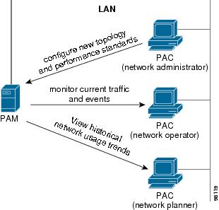
In a network, at least one PAC exists for each PAM and it can be located anywhere convenient. A PAM normally has a PAC installed on it. Figure 1-5 shows how multiple PACs can be connected to a single PAM.
Figure 1-5 Multiple PACs to a Single PAM
In this arrangement, network configuration and analysis tasks can be shared and distributed as needed. The same PAM data is available to all PACs connected to it, assuming the same domain permissions are granted to the respective users.
Figure 1-6 shows how a single PAC can also connect to multiple PAMs. This arrangement allows for easy visibility to many WANs, managed by multiple PAMs, from a single, convenient PAC location.
Figure 1-6 Single PAC to Multiple PAMs
Web Planning and Reporting Clients
The Web Client is a Web browser-based edition of the Planning and Reporting Toolset. The application runs on a Windows PC or UNIX workstation with either Microsoft Internet Explorer or Netscape Navigator Web browser software. (See the "Web Client Requirements" section on page -28 in the Cisco WAN Access Performance Management System Installation and Configuration Guide, 2.0 for browser version requirements.)
The software installation on a PAM includes the Web Planning and Reporting server. A user, referred to as a Web Client, uses the PAM's IP address as a URL to establish IP connectivity and gain access to the Web Planning and Reporting server on that PAM. User access is restricted through password security.
The Web Client platform provides versatility and accessibility. Web Clients who only need to view and generate reports can readily use the Web Client without installing a PAC. Figure 1-7 illustrates how different Web browsers can access the PAM's Planning and Reporting server.
Figure 1-7 Versatility of Web Clients
A Web Client can perform the following set of tasks with the PAM's Web Server:
•
•
•
•
Network Models
The arrangement of Cisco WAPMS components in a network varies according to customer needs. However, two typical customer scenarios are illustrated in this section:
•
•
Subscriber Model
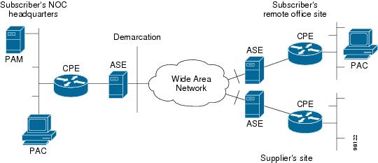
For a WAN service subscriber, the PAM manages one network; that subscriber's network. One domain is established on the PAM to securely hold that subscriber's network configuration and performance data. The PAM resides at the subscriber's NOC. Because the subscriber owns the ASEs in this case, the ASEs are located on the CPE-side of the WAN connection, or demarcation point. The subscriber installs an ASE on each managed circuit and uses a PAC at any location from which access to the PAM is needed.
In Figure 1-8, the PAM is located at NOC headquarters, ASEs are monitoring all the subscriber's circuits, and PACs are used at the NOC headquarters and at a remote office site to view the data. The subscriber's supplier does not use a PAC, although the subscriber monitors the supplier's network circuit with an ASE.
Figure 1-8 Subscriber Deployment Model
Provider Model
For a WAN service provider, the PAM manages many networks—one for each subscriber. The PAM is partitioned into multiple domains, one per subscriber, to securely hold each subscriber's network configuration and performance data. The PAM and a PAC reside at the provider's NOC inside the WAN. Subscribers may have their own PACs to verify the provider's service.
In Figure 1-9, the provider has installed ASEs inside the WAN on all of the subscriber's circuits and the PAM has a separate domain for each subscriber. The provider's PAC can see data for each subscriber's domain. Subscribers A and B have their own PACs that enable them to view data simultaneously with the provider, however, subscribers can see data only for their own domain. Subscriber C has purchased a level of service not including a PAC from the provider.
Figure 1-9 Provider Deployment Model
Network Performance Database
A PAM collects and stores network performance data from all ASEs configured with the Network Configuration tool on a PAC. This data is stored in two databases on the PAM; the short-term and long-term databases collectively referred to as the network performance database.
Data Collection and Storage
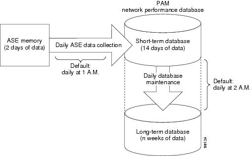
ASEs collect and store network performance data in 15-minute increments for two days. New data continually overwrites the oldest, so the most recent data is always available. This historical data is downloaded to a PAM when ASE data collection is initiated from the PAM. ASEs also communicate current and real-time network performance data directly to a PAC when the PAC is performing troubleshooting, traffic capture, and IP conversations analysis.
The short-term database on the PAM stores 14 days of network performance data in 15-minute increments. This data is downloaded from the ASE each time ASE data collection occurs (daily by default at 1:00 A.M.). Each time database maintenance occurs (daily by default at 2:00 A.M.), data is copied from the short-term database to the long-term database and any data more than 14 days old is purged from the short-term database.
The short-term database also stores network configuration and statistical alarm data for performance monitoring (entered from a PAC), and access control settings (entered from the PAM). This information remains in the short-term database and is updated when new information is entered through the PAC or PAM user interfaces.
The long-term database on the PAM stores up to <n> weeks (52 by default) of network performance data in 1-hour increments for use with the Planning and Reporting Toolset on PACs and Web Clients. The long-term database capacity is determined by the PAM tier at the time of purchase.
Figure 1-10 illustrates how data moves from the ASE to the PAM's short-term database and then to the long-term database.
Figure 1-10 Movement of Network Performance Data
Both ASE data collection and database maintenance, which trigger this data transfer, can be scheduled from a PAC and can be performed on demand from either a PAC or PAM. You can also modify from a PAC the number of weeks of data stored in the long-term database. For more information, see the "Scheduling Database Maintenance on the PAC" section.
Network Performance Data in the Database
Network performance data captured by ASEs and stored in the PAM's network performance database can be categorized as follows:
•
•
•
•