
Table Of Contents
Installing CWM Server Software
First Time Login as User svplus
Checking the CWM Server File System
svplus/config/network.conf file
CWM Gateway Configuration File
Installing CWM Server Software
This chapter provides a step-by-step procedure to install the CWM Release 11 and CiscoView
Release 5.4 software on a CWM server workstation. The CWM Release 11 software installation process uses InstallShield to simplify the process.Before installing the CWM Release 11 software on the CWM workstation, the following software should have already been installed (in the following order):
•
Solaris 2.7 Operating System
•
•
•
•
Refer to Chapter 2 for instructions on installing these products.
Installing CWM Software
To install the CWM Release 11 software, perform the following steps:

Note
Step 1
Step 2
CDROM #1 into the CDROM drive.Step 3
# cd /cdrom/cdrom0# lsStep 4
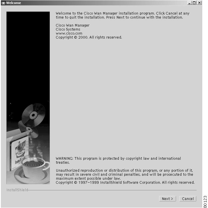
InstallCWM.shfile,begin the install process by entering the following command:# ./InstallCWM.shThe installation classes are loaded (a process that takes several minutes). The CWM Installation Welcome window is displayed, as shown in Figure 3-1.
Figure 3-1 CWM Installation Welcome Window
Step 5
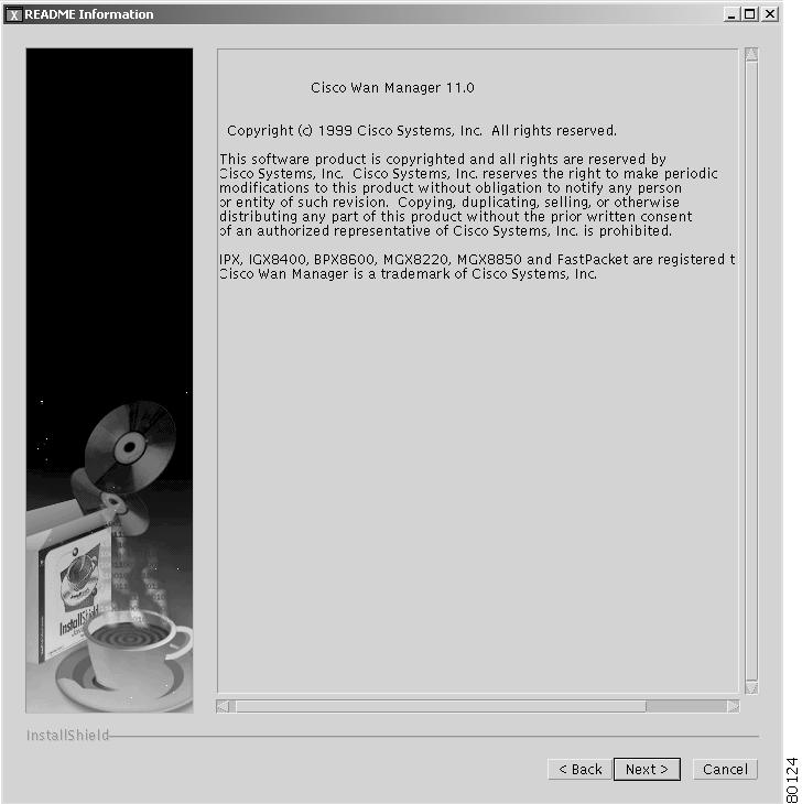
The README Information window, Figure 3-2, is displayed.
Figure 3-2 CWM Installation README Information Window
Step 6
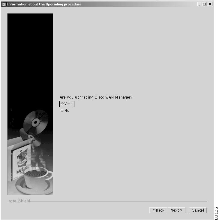
The Information about the Upgrade Procedure window is displayed, as shown in Figure 3-3.
Figure 3-3 Information About the Upgrading Procedure Window
Step 7
The Auto-Partition Disks window is displayed, as shown in Figure 3-4.
Figure 3-4 Auto-Partition Window

Step 8
The Meta Devices window is displayed, as shown in Figure 3-5.
Figure 3-5 Meta Devices Window

Step 9
Note
The Multiple Disk Configuration for Informix window is displayed, as shown in Figure 3-6.
Figure 3-6 Multiple Disk Configuration for Informix Window

Step 10
The Select the Raw Partition for CWM Database window is displayed, as shown in Figure 3-7.
Figure 3-7 Select the Raw Partition for CWM Database Window
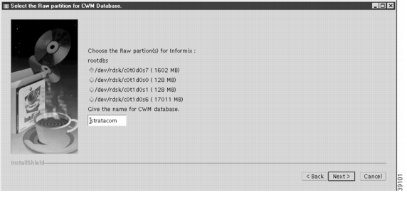
Step 11
In this release of CWM, the database name cannot be changed, accept the default name of stratacom.
Note
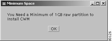
A small window is displayed warning the user that the selected partition must be at least 1 GByte in size (see Figure 3-8).
Figure 3-8 Minimum Space Warning
Step 12
When Next has been clicked, the CWM FTP Information window is displayed as shown in Figure 3-9.
Figure 3-9 CWM FTP Information Window
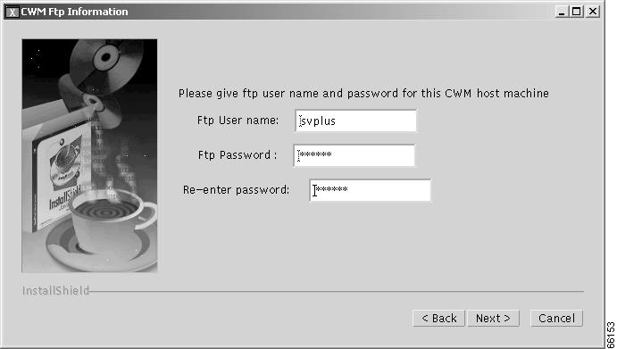
Step 13
Note
After entering the FTP user name and password, click Next.
The Choose Destination Directory window is displayed, as shown in Figure 3-10.
Figure 3-10 Choose Destination Directory Window
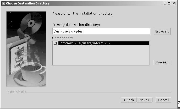
Accept the default destination directory of usr/users/svplus and click Next.
Although the destination directory is editable, this release supports only the default directory.
The Install Orbix window is displayed, as shown in Figure 3-11.
Figure 3-11 Install Orbix Window
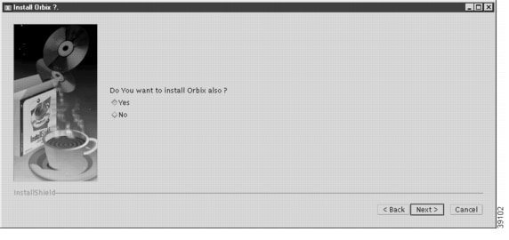
Orbix is the software component that provides the communication capability between CWM gateways.
Step 14
The Enter Domain Name window is displayed as shown in Figure 3-12.
Note
Figure 3-12 Enter the Domain Name Window
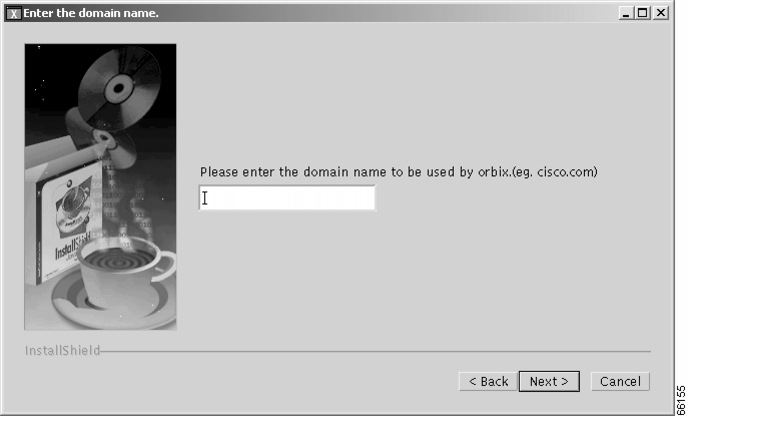
Step 15
This information allows the CWM client workstations access to the database. Also ensure that the workstation and the domain is reachable. You can enter the ping command to test this.
The only reason to leave the Domain Name field empty (or blank) would be for a standalone CWM server never to have client workstations.
After entering the domain name, click Next. The Install CiscoView window is displayed, as shown in Figure 3-13.
Figure 3-13 Install CiscoView Window

Note
Step 16
If Yes is selected, the Enter CiscoView home window is displayed as shown in Figure 3-14.
Caution
If CiscoView is installed (from a previous installation) either select No and Continue or go back, uninstall CiscoView, restart the install process, and select Yes at the CiscoView window.
Figure 3-14 Enter CiscoView Home Window
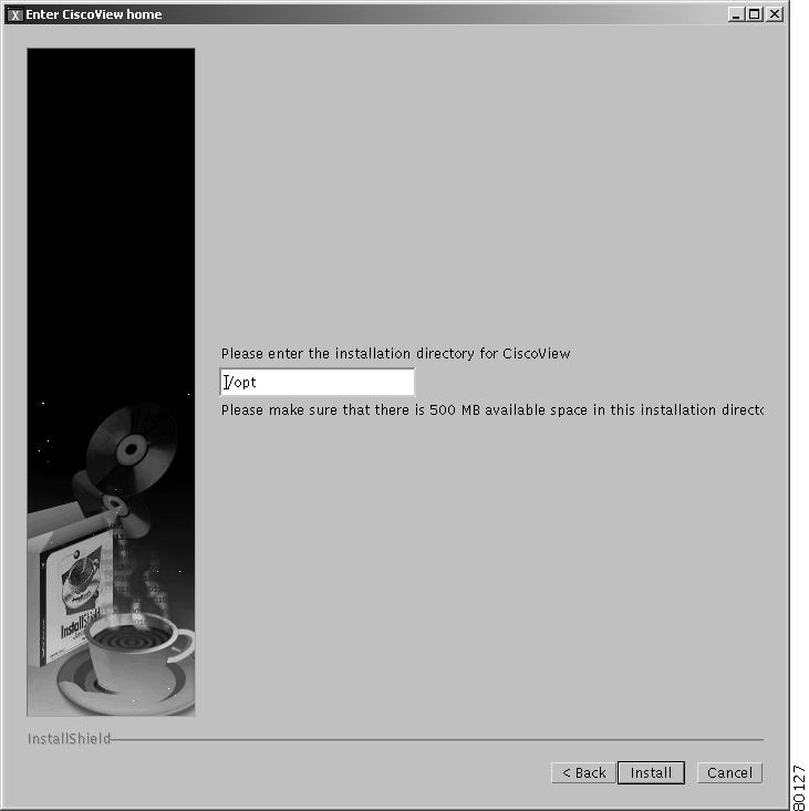
Step 17
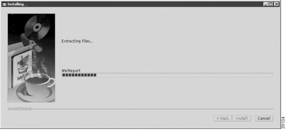
The software installation process begins. This process will take from 30 to 60 minutes depending on the speed and resources of the CWM workstation. The installation window shows a dynamic indicator bar, which moves across the window, indicating the progress of the installation process, as shown in Figure 3-15.
A small log window is also displayed showing entries to the install log as they are entered.
Figure 3-15 Installation Progress Indicator (extracting files)
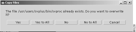
If the CWM system was installed previously, a message appears telling the user that files already exist and permission is requested to overwrite the files with new files. This message is shown in Figure 3-16. Click Yes to All.
Figure 3-16 Copy Files Message
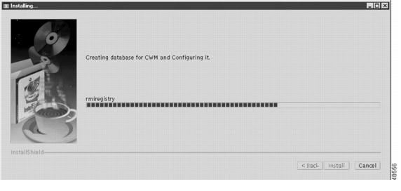
After extracting the necessary CWM program files, the window refreshes and the installation process begins creating and configuring the database. The installation window shows a dynamic indicator bar, which moves across the window, indicating the progress of the database creation process, as shown in Figure 3-17.
Figure 3-17 Installation Progress Indicator (database creation)
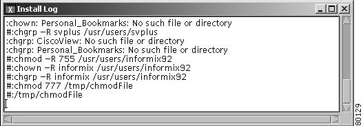
An Install Log window is also displayed (see Figure 3-18).
Figure 3-18 Install Log
A dialog box displays informing you that the installation is complete, as shown in Figure 3-19.
Figure 3-19 Installation Complete Window

Step 18
The software installation process is completed. The Install Shield window closes.
The first time (and only the first) that CWM is installed, the system will display a message stating that the kernel has been changed. Click OK to reboot the system
The reboot sequence aligns the cylinders of your hard disks and gracefully shuts down the Solaris operating system.
Step 19
Note
Post Installation Tasks
After the CWM installation is complete the following configuration tasks should be completed.
If you haven't already done so eject the CWM CD-ROM by entering the eject command in the terminal window.
First Time Login as User svplus
After completing the CWM Release 11 software installation, perform the following steps when you log in to CWM as user svplus.
Step 1
Step 2
Step 3
Step 4
Move this terminal window to the upper right corner of the screen.
Step 5
Lower the height to display four lines and move this window so that it rests above the CDE menu bar. This window provides a display of workstation system messages.
Step 6
The Style Manager window is displayed.
Step 7
If you prefer to use the screen saver, highlight choice(s) and start the screen saver at 29 minutes. Start the screen lock at 30 minutes, click OK.
Step 8
Do the same to all four screens,. They are labeled One, Two, Three and Four in the CDE icon bar. In Four click OK and return to screen One. This action helps to conserve workstation resources.
Step 9
The next login session will come up using this same screen configuration. Click OK and close the Style Manager.
Step 10
% cd /usr/users/svplus/config% vi network.confStep 11
Note
Checking the CWM Server File System
At the CWM workstation, log in as user root, and examine the following files.
•
•
•
•
•
•
•
•
•
Note
/etc/hosts
Examine the /etc/hosts file and check that the file contains a nodename and IP address for all nodes. The IP address should be one that CWM can use for network discovery (see following paragraphs). Enter the correct nodenames and addresses for any missing nodes.
To view the /etc/hosts file, enter the following command:
host% more /etc/hostsUse vi Editor to enter items into the file.
IPX and MGX (Rel 1.x, 2.0 and up to 2.1.60) Nodes
For each node:
Enter the ATM0 or NWIP address and the node name.
Enter the LnPci0 or LANIP address and the nodename followed by an identifier such as -l, or -lan).
Example:
172.70.207.9	mgx1
192.0.0.9	mgx1-l
MGX (Rel 2.1.70 and above) Nodes
For each node:
Enter the IP address used in option 8 of the cnfndparms command. This address can be displayed at the node by entering the dspndparms command.
Example:
172.70.209.9 mgx4BPX Nodes
For each node:
Enter the node's IP address and the node name.
Example:
192.0.0.8 bpx1Example Host File
As an example, a hosts file might look like the following example:
# MGX Rel 1, 2.0, up to 2.1.60 nodes172.70.207.9 mgx1 192.0.0.9 mgx1-l172.70.207.6 mgx2 192.0.0.6 mgx2-l172.70.207.4 mgx3 192.0.0.4 mgx3-l##MGX Rel 2.1.70 and up nodes172.70.209.9 mgx4172.70.209.8 mgx5172.70.209.7 mgx6172.70.209.6 mgx7##BPX nodes192.0.0.8 bpx1192.0.0.9 bpx2192.0.0.10 bpx3/etc/netmasks
Examine the /etc/netmasks file for all subnet and netmask entries. To view the /etc/netmasks file, enter the following command:
host% more /etc/netmasks/etc/rc2.d/S72inetsvc
Examine the /etc/rc2.d/S72inetsvc file to ensure that the IP relay address points to the gateway node. To view the /etc/rc2.d/S72inetsvc file, enter the following command:
host% more /etc/rc2.d/S72inetsvcUse the vi Editor to open the S72inetsvc file and find the following line:
/usr/sbin/route add -interface -netmask "224.0.0.0" "224.0.0.0" "$mcastif")&Add the following line directly below that line
/usr/sbin/route add net 10.10.10.0 209.165.200.225  1  (use your site's valid IP
addresses)
Note
/etc/defaultrouter
Examine the /etc/defaultrouter file. To view the /etc/defaultrouter file, enter the following command:
host% more /etc/defaultrouter
Note
If the router IP address is not currently in the file, use the vi Editor to add a line containing the IP address of the default router to which the CWM workstation is attached.
Note
usr/users/svplus/.cshrc
Use the vi editor to modify .cshrc as follows:
vi usr/users/svplus/.cshrc
Change the line:
setenv PATH$ORBIXROOT/bin:$PATH
to
setenv PATH$ORBIXROOT/bin:/opt/NSCPcom:$PATHAdd the following lines to the end of the file.
setenv PATH "netscape path":$PATH
setenv MOZILLA_HOME "netscape path"
Exit vi.svplus/config/network.conf file
The network.conf file is located in the /usr/users/svplus/config directory.
The user should modify this file to specify networks parameters for each network to be discovered and managed.This file can describe multiple networks where each network can be any one of the following types.
•
•
•
For each network specified in the network.conf file, its entry consists of the following fields.
•
•
•
•
•
•
NETWORK
The NETWORK field has the following format.
NETWORK: <Network Name>
When describing a network's parameters, NETWORK must be the first parameter.
The Network name cannot have more than 10 characters and cannot contain a space.
Note
NETWORK ID
The NETWORK ID field has the following format.
NETWORK_ID: <Network ID>
Network ID is optional. If it is specified, the Network ID must be a unique numeric value in the range in [1, 32000].
Note
GATEWAYS
The GATEWAYS field has the following formats.
GATEWAYS: <Gateway Name(s)> (used for AutoRoute and PNNI).
AR-GATEWAYS: <Gateway Name> (used for AutoRoute segments in a Hybrid network type).
PNNI-GATEWAYS: <Gateway Name(s)> (used for PNNI segments in a Hybrid network type).
The user should enter the name(s) of any gateways that CWM is to use for network discovery.
The rules for gateways parameters depend upon the network type.
AutoRoute
Use the GATEWAYS: <Gateway Name> format and specify one (and only one) network node to be used as the AutoRoute gateway.
PNNI
Use the GATEWAYS: <Gateway Name> format and specify one or more network nodes to be used as PNNI gateways. If more than one gateway is specified for the network, the names should be separated by commas.
Hybrid
This field is used to specify which gateways should be used for the AutoRoute and PNNI segments of the network.
Use the PNNI-GATEWAYS: <Gateway Names> format to specify one or more network nodes to be used as PNNI gateways. If more than one gateway is specified for the PNNI segment, the names should be separated by commas.
Use the AR-GATEWAYS: <Gateway Names> format and specify one (and only one) network node to be used as an AutoRoute gateway.
Note
.DISCOVERY PROTOCOL
This field is used to specify the network type and has the following format.
DISCOVERY PROTOCOL: <Protocol Name>
The Protocol Name can be either AUTOROUTE or PNNI or HYBRID.
AUTOROUTE is used to discover Auto Route networks .
PNNI is used for ILMI or PNNI discovery of PNNI networks.
HYBRID is used to discover networks that contain both AutoRoute and PNNI segments.
IP REACHABILITY FLAG
The IP REACHABILITY FLAG field is used to specify which IP address method is to be used for managing network nodes. This field is used for AutoRoute networks and Hybrid AutoRoute segments only. It is ignored for PNNI networks or segments.The IP REACHABILITY FLAG field has the following format.
IP REACHABILITY FLAG:<Ip Flag>
IP Flag can be set to NWIP_ON or NWIP_OFF or LANIP.
NWIP_ON — All the routing nodes in the network are managed using their nw ip addresses.
NWIP_OFF — All the routing nodes in the network are managed through the Gateway. The Gateway then routes packets to the individual routing nodes on the corresponding routing trunks.
LANIP — All the nodes in the network are managed using Lan IP. The AUTOROUTE Gateway node is always managed using the LAN IP. By specifying "LANIP", all management traffic (including link0/link1, snmp and tftp) is sent to each node (routing node or feeders) using their Lan IP addresses.
If NWIP is set to ON or OFF, management messages use the managed network for delivery and are therefore considered to be in-band. A setting of LAN IP, on the other hand, uses a separate LAN (or LAN emulation) network for message delivery and is therefore considered to be out-of-band.
OPTIONAL
The OPTIONAL field is used to specify a number of options associated with the IP REACHABILITY FLAG and has the following format.
OPTIONAL: "List of Parameters for Auto Route Networks"
This field is mandatory for AutoRoute networks and AutoRoute segments in Hybrid networks. If this field is not specified, Auto Route networks and segments WILL NOT be discovered
OPTIONAL does not apply for PNNI networks and is ignored.
The OPTIONAL field has five sub-fields (options) as follows:
•
•
•
•
•
TIMEOUT
Link timeout value. The amount of time to wait before resending a message to an Cisco IGX 8400 and Cisco BPX 8600 when a response is not received. Default value is 7.
RETRANSMIT
Link retry count. The number of times CWM will retransmit a message before it declares the link down. Default value is 6.
THROTTLE
Download throttling timeout value. Default value is 0
ACKNOWLEDGE
ACK timeout value used during the download process. When an acknowledgment to a configuration message sent to an Cisco IGX 8400, or Cisco BPX 8600 is not received within this time period, the message is sent again. Default value is 30.
BLOCKSIZE
Block size used for an Cisco IGX 8400, or Cisco BPX 8600 configuration upload. Default value is 1024.
Note
Network.conf Examples
1. Discover an AutoRoute Network
NETWORK:Network1
GATEWAYS:B8650_SJ
DISCOVERY PROTOCOL:AUTOROUTE
IP REACHABILITY FLAG:NWIP_ON
OPTIONAL:"TIMEOUT = 7, RETRANSMIT = 6, THROTTLE = 0, ACKNOWLEDGE = 30, BLOCKSIZE = 1024"
2. Discover a PNNI network
NETWORK:Network2
GATEWAYS:M8850_LA
DISCOVERY PROTOCOL:PNNI
Note
3. Discover a HYBRID Network
#NETWORK:Network3
#PNNI-GATEWAYS:M8850_LA, M8850_CH
#AR-GATEWAYS:B8650_LA
#DISCOVERY PROTOCOL:HYBRID
#IP REACHABILITY FLAG:NWIP_ON
#OPTIONAL:"TIMEOUT = 7, RETRANSMIT = 6, THROTTLE = 0, ACKNOWLEDGE = 30, BLOCKSIZE = 1024"
CWM Gateway Configuration File
If the upgraded CWM workstation is part of a multiple CWM gateway configuration, check the CWMGateway.conf file and ensure that the DomainGatewayList contains all the stations in the Gateway domain.
For example:
host% cd usr/users/svplus/confighost% more CWMGateway.confCheck the DomainGatewayList portion of this file.
## Default: DomainGatewayList
## Usage: DomainGateWayList tmonda dilbag sgharat
DomainGatewayList CWM1 CWM2 CWM3
In this example, CWM1, CWM2, and CWM3 are the names of the CWM gateways.
/system
Change directory to /system and enter the ls command. Check to see that all required HPOV PSOV_XXXXX patches have been installed.
# cd /system# ls/etc/system
Check to see that the CWM installation process added the semaphores required for Solaris and HP OpenView operability
(set semsys:seminfo_semmsl=30).forceload: sys/shmsysforceload: sys/semsysset semsys:seminfo_semaem=16384set semsys:seminfo_semmap=66set semsys:seminfo_semmni=4096set semsys:seminfo_semmns=4096set semsys:seminfo_semmnu=4096set semsys:seminfo_semume=64set semsys:seminfo_semvmx=32767set semsys:seminfo_semmsl=30set shmsys:shminfo_shmmax=268435456set shmsys:shminfo_shmmin=100set shmsys:shminfo_shmmni=100set shmsys:shminfo_shmseg=100Reboot the Workstation
After completing the configuration, reboot the workstation.
# sync ;sync ;reboot