- Signalling Overview
- Configuring RSVP
- Control Plane DSCP Support for RSVP
- Configuring RSVP Support for Frame Relay
- RSVP Scalability Enhancements
- RSVP Support for ATM/PVCs
- RSVP Local Policy Support
- RSVP Refresh Reduction and Reliable Messaging
- RSVP Support for RTP Header Compression, Phase 1
- RSVP Message Authentication
- RSVP---Previous Hop Overwrite
- RSVP Application ID Support
- RSVP Fast Local Repair
- RSVP Interface-Based Receiver Proxy
- RSVP--VRF Lite Admission Control
- Configuring RSVP Support for LLQ
- Configuring RSVP-ATM QoS Interworking
- Configuring COPS for RSVP
- RSVP Aggregation
- MPLS TE---Tunnel-Based Admission Control (TBAC)
- Configuring Subnetwork Bandwidth Manager
- Contents
- Prerequisites for RSVP—Previous Hop Overwrite
- Restrictions for RSVP—Previous Hop Overwrite
- Information About RSVP—Previous Hop Overwrite
- How to Configure RSVP—Previous Hop Overwrite
- Configuration Examples for RSVP—Previous Hop Overwrite
- Additional References
- Command Reference
- Feature Information for RSVP—Previous Hop Overwrite
- Glossary
RSVP—Previous Hop Overwrite
The RSVP—Previous Hop Overwrite feature allows you to configure a Resource Reservation Protocol (RSVP) router, on a per interface basis, to populate an address other than the native interface address in the previous hop (PHOP) address field of the PHOP object when forwarding a PATH message onto that interface. You can configure the actual address for the router to use or an interface, including a loopback, from which to borrow the address.
Finding Feature Information in This Module
Your Cisco IOS software release may not support all of the features documented in this module. For the latest feature information and caveats, see the release notes for your platform and software release. To reach links to specific feature documentation in this module and to see a list of the releases in which each feature is supported, use the "Feature Information for RSVP—Previous Hop Overwrite" section.
Finding Support Information for Platforms and Cisco IOS and Catalyst OS Software Images
Use Cisco Feature Navigator to find information about platform support and Cisco IOS and Catalyst OS software image support. To access Cisco Feature Navigator, go to http://www.cisco.com/go/cfn. An account on Cisco.com is not required.
Contents
•![]() Prerequisites for RSVP—Previous Hop Overwrite
Prerequisites for RSVP—Previous Hop Overwrite
•![]() Restrictions for RSVP—Previous Hop Overwrite
Restrictions for RSVP—Previous Hop Overwrite
•![]() Information About RSVP—Previous Hop Overwrite
Information About RSVP—Previous Hop Overwrite
•![]() How to Configure RSVP—Previous Hop Overwrite
How to Configure RSVP—Previous Hop Overwrite
•![]() Configuration Examples for RSVP—Previous Hop Overwrite
Configuration Examples for RSVP—Previous Hop Overwrite
•![]() Feature Information for RSVP—Previous Hop Overwrite
Feature Information for RSVP—Previous Hop Overwrite
Prerequisites for RSVP—Previous Hop Overwrite
You must configure RSVP on one or more interfaces on at least two neighboring routers that share a link within the network.
Restrictions for RSVP—Previous Hop Overwrite
•![]() This feature is supported only on integrated services routers (ISRs).
This feature is supported only on integrated services routers (ISRs).
•![]() Unnumbered IP addresses are not allowed.
Unnumbered IP addresses are not allowed.
Information About RSVP—Previous Hop Overwrite
To use the RSVP—Previous Hop Overwrite feature, you should understand the following concepts:
•![]() Feature Overview of RSVP—Previous Hop Overwrite
Feature Overview of RSVP—Previous Hop Overwrite
•![]() Benefits of RSVP—Previous Hop Overwrite
Benefits of RSVP—Previous Hop Overwrite
Feature Overview of RSVP—Previous Hop Overwrite
An RSVP PATH message contains a PHOP object that is rewritten at every RSVP hop. The object's purpose is to enable an RSVP router (R1) sending a PATH message to convey to the next RSVP router (R2) downstream that the previous RSVP hop is R1. R2 uses this information to forward the corresponding RESV message upstream hop-by-hop towards the sender.
The current behavior in Cisco IOS software is that an RSVP router always sets the PHOP address to the IP address of the egress interface onto which the router transmits the PATH message.
There are situations where, although some IP addresses of R1 are reachable, the IP address of its egress interface is not reachable from a remote RSVP router R2. This results in the corresponding RESV message generated by R2 never reaching R1 and the reservation never being established.
Figure 1 shows a sample network in which the preceding scenario occurs and no reservation is established.
Figure 1 Sample PHOP Network with Unified Communcations Manager (CM)
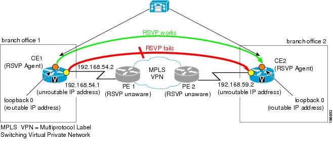
In Figure 1, when a call is made from branch office 1 to branch office 2, the RSVP Agent on customer edge (CE)1 tries to set up a session with CE2 and sends a PATH message. CE1 stamps its outgoing interface IP address (192.168.54.1), which is an unroutable IP address, in the PHOP object of the PATH message. This PATH message is tunneled across the service provider network and processed by CE2. CE2 records this IP address in the PHOP object of the received PATH message in the PSB (Path State Block).
CE2 has a receiver proxy configured for the destination address of the session. As a result, when CE2 replies back with a RESV message, CE2 tries to send the RESV message to the IP address that CE2 had recorded in its PSB. Because this IP address (192.168.54.1) is unroutable from CE2, the RESV message will fail.

Note ![]() Once you configure a source address on an interface, RSVP always uses the RSVP-overwritten address rather than the native interface address.
Once you configure a source address on an interface, RSVP always uses the RSVP-overwritten address rather than the native interface address.
Benefits of RSVP—Previous Hop Overwrite
Flexibility and Customization
You can configure a CE to populate the PHOP object in a PATH message with an address that is reachable in the customer VPN. This enables the RESV message to find its way back towards the sender so that reservations can be established.
How to Configure RSVP—Previous Hop Overwrite
•![]() Configuring a Source Address or a Source Interface (required)
Configuring a Source Address or a Source Interface (required)
•![]() Verifying the PHOP Configuration (optional)
Verifying the PHOP Configuration (optional)
Configuring a Source Address or a Source Interface
Perform this task to configure a source address or a source interface.
SUMMARY STEPS
1. ![]() enable
enable
2. ![]() configure terminal
configure terminal
3. ![]() interface type number
interface type number
4. ![]() ip rsvp bandwidth [interface-kbps] [single-flow-kbps]
ip rsvp bandwidth [interface-kbps] [single-flow-kbps]
5. ![]() ip rsvp source {address ip-address | interface type number}
ip rsvp source {address ip-address | interface type number}
6. ![]() end
end
DETAILED STEPS
Verifying the PHOP Configuration
Note ![]() You can use the following show command in user EXEC or privileged EXEC mode.
You can use the following show command in user EXEC or privileged EXEC mode.
SUMMARY STEPS
1. ![]() enable
enable
2. ![]() show ip rsvp interface [detail] [interface-type interface-number]
show ip rsvp interface [detail] [interface-type
interface-number]
3. ![]() exit
exit
DETAILED STEPS
Configuration Examples for RSVP—Previous Hop Overwrite
This section provides the following configuration examples for RSVP—Previous Hop Overwrite:
•![]() Examples: Configuring RSVP—Previous Hop Overwrite
Examples: Configuring RSVP—Previous Hop Overwrite
•![]() Examples: Verifying RSVP—Previous Hop Overwrite Configuration
Examples: Verifying RSVP—Previous Hop Overwrite Configuration
Examples: Configuring RSVP—Previous Hop Overwrite
•![]() Configuring a Source Address on Router CE1 for the CE1-to-PE1 Interface
Configuring a Source Address on Router CE1 for the CE1-to-PE1 Interface
•![]() Configuring a Source Address on Router CE2 for the CE2-to-PE2 Interface
Configuring a Source Address on Router CE2 for the CE2-to-PE2 Interface
•![]() Creating a Listener Proxy on Router C2
Creating a Listener Proxy on Router C2
•![]() Creating a Session from Router C1 to Router C2
Creating a Session from Router C1 to Router C2
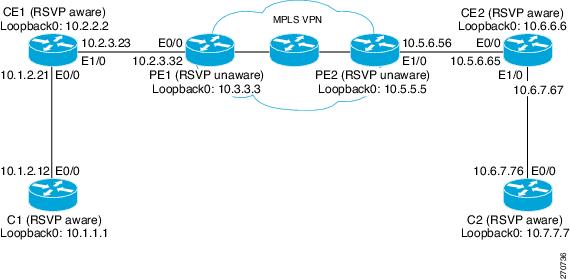
Figure 2 shows a sample network in which PHOP is configured.
Figure 2 Sample PHOP Network
Configuring a Source Address on Router CE1 for the CE1-to-PE1 Interface
The following example configures a source address on the CE1-to-PE1 (Ethernet 1/0) interface in Figure 2:
Router(CE1)# configure terminal
Enter configuration commands, one per line. End with CNTL/Z.
Router(CE1)(config)# interface ethernet 1/0
Router(CE1)(config-if)# ip rsvp source address 10.2.2.2 <--------------------
Router(CE1)(config-if)# end
Configuring a Source Address on Router CE2 for the CE2-to-PE2 Interface
The following example configures a source address on the CE2-to-PE2 (Ethernet 0/0) interface in Figure 2:
Router(CE2)# configure terminal
Enter configuration commands, one per line. End with CNTL/Z.
Router(CE2)(config)# interface ethernet 0/0
Router(CE2)(config-if)# ip rsvp source address 10.6.6.6 <---------------------
Router(CE2)(config-if)# end
Creating a Listener Proxy on Router C2
The following example creates a listener proxy on Router C2 and requests that the receiver reply with a RESV message for the flow if the PATH message destination is 10.7.7.7 in Figure 2:
Router(C2)# configure terminal
Enter configuration commands, one per line. End with CNTL/Z.
Router(C2)(config)# ip rsvp listener 10.7.7.7 any any reply <--------------------
Router(C2)(config)# end
Creating a Session from Router C1 to Router C2
The following example creates an RSVP session from Router C1 to Router C2:
Router(C1)# configure terminal
Enter configuration commands, one per line. End with CNTL/Z.
Router(C1)(config)# ip rsvp sender-host 10.7.7.7 10.1.1.1 UDP 100 200 1 1 <-------------
Router(C1)(config)# end
Examples: Verifying RSVP—Previous Hop Overwrite Configuration
•![]() Verifying the Source Address on Router CE1 for the CE1-to-PE1 Interface
Verifying the Source Address on Router CE1 for the CE1-to-PE1 Interface
•![]() Verifying the Source Address on Router CE2 for the CE2-to-PE2 Interface
Verifying the Source Address on Router CE2 for the CE2-to-PE2 Interface
•![]() Verifying the Listener Proxy on Router C2
Verifying the Listener Proxy on Router C2
•![]() Verifying the Session from Router C1 to Router C2
Verifying the Session from Router C1 to Router C2
•![]() Verifying the Next-Hop Address
Verifying the Next-Hop Address
Verifying the Source Address on Router CE1 for the CE1-to-PE1 Interface
The following example verifies the source address (10.2.2.2) configured on the CE1-to-PE1 (Ethernet 1/0) interface in Figure 2:
Router(CE1)# show ip rsvp interface detail ethernet 1/0
Et1/0:
RSVP: Enabled
Interface State: Up
Bandwidth:
Curr allocated: 1K bits/sec
Max. allowed (total): 100K bits/sec
Max. allowed (per flow): 100K bits/sec
Max. allowed for LSP tunnels using sub-pools: 0 bits/sec
Set aside by policy (total): 0 bits/sec
Admission Control:
Header Compression methods supported:
rtp (36 bytes-saved), udp (20 bytes-saved)
Traffic Control:
RSVP Data Packet Classification is ON via CEF callbacks
Signalling:
DSCP value used in RSVP msgs: 0x3F
Number of refresh intervals to enforce blockade state: 4
Ip address used in RSVP objects: 10.2.2.2 <------------------------------------
Authentication: disabled
Key chain: <none>
Type: md5
Window size: 1
Challenge: disabled
Hello Extension:
State: Disabled
Verifying the Source Address on Router CE2 for the CE2-to-PE2 Interface
The following example verifies the source address configured on the CE2-to-PE2 (Ethernet 0/0) interface in Figure 2:
Router(CE2)# show ip rsvp interface detail ethernet 0/0
Et0/0:
RSVP: Enabled
Interface State: Up
Bandwidth:
Curr allocated: 0 bits/sec
Max. allowed (total): 100K bits/sec
Max. allowed (per flow): 100K bits/sec
Max. allowed for LSP tunnels using sub-pools: 0 bits/sec
Set aside by policy (total): 0 bits/sec
Admission Control:
Header Compression methods supported:
rtp (36 bytes-saved), udp (20 bytes-saved)
Traffic Control:
RSVP Data Packet Classification is ON via CEF callbacks
Signalling:
DSCP value used in RSVP msgs: 0x3F
Number of refresh intervals to enforce blockade state: 4
Ip address used in RSVP objects: 10.6.6.6 <-----------------------------------
Authentication: disabled
Key chain: <none>
Type: md5
Window size: 1
Challenge: disabled
Hello Extension:
State: Disabled
Verifying the Listener Proxy on Router C2
The following example verifies the listener proxy configured on Router C2 in Figure 2:
Router(C2)# show ip rsvp listeners
To Protocol DPort Description Action
10.7.7.7 <-------- any any RSVP Proxy reply
Verifying the Session from Router C1 to Router C2
The following example verifies that the session configured between Router C1 and Router C2 in Figure 2 is up:
Router(C1)# show ip rsvp reservation
To From Pro DPort Sport Next Hop I/F Fi Serv BPS
10.7.7.7 10.1.1.1 UDP 100 200 10.1.2.21 Et0/0 FF RATE 1K
Verifying the PHOP Address
The following example on Router CE2 verifies the source address configured on the CE1-to-PE1 interface in Figure 2 as the PHOP address:
Router(CE2)# show ip rsvp sender detail
PATH:
Destination 10.7.7.7, Protocol_Id 17, Don't Police , DstPort 100
Sender address: 10.1.1.1, port: 200
Path refreshes:
arriving: from PHOP 10.2.2.2 on Et0/0 every 30000 msecs <-------------------
Traffic params - Rate: 1K bits/sec, Max. burst: 1K bytes
Min Policed Unit: 0 bytes, Max Pkt Size 2147483647 bytes
Path ID handle: CA000406.
Incoming policy: Accepted. Policy source(s): Default
Status:
Output on Ethernet1/0. Policy status: Forwarding. Handle: 0E000402
Policy source(s): Default
Verifying the Next-Hop Address
The following example on Router CE1 verifies the source address configured on the CE2-to-PE2 interface in Figure 2 as the next-hop address:
Router(CE1)# show ip rsvp reservation detail
RSVP Reservation. Destination is 10.7.7.7, Source is 10.1.1.1,
Protocol is UDP, Destination port is 100, Source port is 200
Next Hop: 10.6.6.6 on Ethernet1/0 <---------------------------------------------
Reservation Style is Fixed-Filter, QoS Service is Guaranteed-Rate
Resv ID handle: 03000400.
Created: 07:01:40 IST Tue Mar 25 2008
Average Bitrate is 1K bits/sec, Maximum Burst is 1K bytes
Min Policed Unit: 0 bytes, Max Pkt Size: 0 bytes
Status:
Policy: Forwarding. Policy source(s): Default
Additional References
The following sections provide references related to the RSVP—Previous Hop Overwrite feature.
Related Documents
Standards
|
|
|
|---|---|
No new or modified standards are supported by this feature, and support for existing standards has not been modified by this feature. |
— |
MIBs
RFCs
Technical Assistance
Command Reference
The following commands are introduced or modified in the feature or features documented in this module. For information about these commands, see the Cisco IOS Quality of Service Solutions Command Reference at http://www.cisco.com/en/US/docs/ios/qos/command/reference/qos_book.html. For information about all Cisco IOS commands, use the Command Lookup Tool at http://tools.cisco.com/Support/CLILookup or the Cisco IOS Master Command List, All Releases, at http://www.cisco.com/en/US/docs/ios/mcl/allreleasemcl/all_book.html.
•![]() debug ip rsvp
debug ip rsvp
•![]() ip rsvp source
ip rsvp source
•![]() show ip rsvp interface
show ip rsvp interface
Feature Information for RSVP—Previous Hop Overwrite
Table 1 lists the release history for this feature.
Not all commands may be available in your Cisco IOS software release. For release information about a specific command, see the command reference documentation.
Use Cisco Feature Navigator to find information about platform support and software image support. Cisco Feature Navigator enables you to determine which Cisco IOS and Catalyst OS software images support a specific software release, feature set, or platform. To access Cisco Feature Navigator, go to http://www.cisco.com/go/cfn. An account on Cisco.com is not required.
Note ![]() Table 1 lists only the Cisco IOS software release that introduced support for a given feature in a given Cisco IOS software release train. Unless noted otherwise, subsequent releases of that Cisco IOS software release train also support that feature.
Table 1 lists only the Cisco IOS software release that introduced support for a given feature in a given Cisco IOS software release train. Unless noted otherwise, subsequent releases of that Cisco IOS software release train also support that feature.
Glossary
QoS—quality of service. A measure of performance for a transmission system that reflects its transmission quality and service availability.
RSVP—Resource Reservation Protocol. A protocol that supports the reservation of resources across an IP network. Applications running on IP end systems can use RSVP to indicate to other nodes the nature (bandwidth, jitter, maximum burst, and so on) of the packet streams that they want to receive.
RSVP Agent—Implements a Resource Reservation Protocol (RSVP) agent on Cisco IOS voice gateways that support Unified CM.
Unified Communcations Manager (CM)—The software-based, call-processing component of the Cisco IP telephony solution. The software extends enterprise telephony features and functions to packet telephony network devices such as IP phones, media processing devices, voice-over-IP (VoIP) gateways, and multimedia applications.
 Feedback