The following example shows the configuration of the routers before the QoS policy map is verified.
Client Configuration
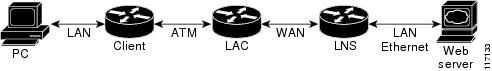
When you log in to the PC, a PPPoE session is established at the client that faces the LAC. This PPPoE session is forwarded
through the L2TP tunnel from the LAC to the LNS at which point the PPPoE session terminates.
To apply QoS sessions to the user traffic that originates from the PC to the web server and to the traffic that originates
from the web server to the PC, you should apply a QoS policy map to the user session on the LAC in the input and output directions.
The classification will be based on the user traffic that originates at the PC and the web traffic that originates at the
web server.
This topology supports bidirectional traffic, meaning that traffic can flow from the PC to the web server and from the web
server to the PC.
username xyz@cisco.com password 0 password1
username qos4-72a password 0 password1
username qos4-72b password 0 password1
aaa authentication ppp default local
aaa session-id common
ip cef
vpdn enable
!
vpdn-group 1
 request-dialin
  protocol pppoe
!
interface ATM0/0/0
 no ip address
 no ip redirects
 no ip proxy-arp
 no ip mroute-cache
 load-interval 30
 no atm ilmi-keepalive
!
interface ATM0/0/0.1 point-to-point
 pvc 0/100
  encapsulation aal5snap
  pppoe max-sessions 100
  pppoe-client dial-pool-number 1
 !
 interface Dialer1
  mtu 1492
  ip address negotiated
  encapsulation ppp
  dialer pool 1
  no peer default ip address
  no cdp enable
  ppp authentication chap callin
  ppp chap hostname xyz@cisco.com
  ppp chap password 0 cisco
  ppp ipcp dns request
!
LAC Configuration
The following example shows that the interfaces between the client and the LAC are ATM5/0 interfaces.
username xyz@cisco.com password 0 password1
username qos4-72a password 0 password1
username qos4-72b password 0 password1
aaa new-model
!
!
aaa authentication ppp default local
aaa session-id common
ip cef
vpdn enable
!
vpdn-group 1
 accept-dialin
  protocol pppoe
  virtual-template 1
!
vpdn-group 2
 request-dialin
  protocol l2tp
  domain cisco.com
 initiate-to ip 10.10.101.2
 local name lac
 no l2tp tunnel authentication
 ip tos reflect
!
interface Serial0/0/0
 bandwidth 2015
 ip address 10.10.100.1 255.255.255.0
 no ip redirects
 no ip proxy-arp
 load-interval 30
 no keepalive
 no cdp enable
!
interface ATM0/0/0
 no ip address
 no ip redirects
 no ip proxy-arp
 load-interval 30
 no atm ilmi-keepalive
!
interface ATM0/0/0.1 point-to-point
 pvc 0/100
  encapsulation aal5snap
  pppoe max-sessions 100
  protocol ppp Virtual-Template1
  protocol pppoe
!
!
interface Virtual-Template1
 mtu 1492
 no ip address
 no peer default ip address
 ppp authentication chap
!
LNS Configuration
The following example shows that the interface between the LAC and the LNS is a Serial3/6 interface.
username xyz@cisco.com password 0 password1
username qos4-72b password 0 password1
username qos4-72a password 0 password1
aaa new-model
!
!
aaa authentication ppp default local
aaa session-id common
ip cef
vpdn enable
!
vpdn-group 1
 accept-dialin
  protocol any
  virtual-template 1
 terminate-from hostname lac
 local name lns
 lcp renegotiation always
 no l2tp tunnel authentication
 ip tos reflect
!
interface Serial0/0/0
 bandwidth 2015
 ip address 10.10.100.1 255.255.255.0
 no ip redirects
 no ip proxy-arp
 no ip mroute-cache
 load-interval 30
 no keepalive
 no cdp enable
!

 Feedback