- Signalling Overview
- Configuring RSVP
- Control Plane DSCP Support for RSVP
- Configuring RSVP Support for Frame Relay
- RSVP Scalability Enhancements
- RSVP Support for ATM/PVCs
- RSVP Local Policy Support
- RSVP Refresh Reduction and Reliable Messaging
- RSVP Support for RTP Header Compression, Phase 1
- RSVP Message Authentication
- RSVP---Previous Hop Overwrite
- RSVP Application ID Support
- RSVP Fast Local Repair
- RSVP Interface-Based Receiver Proxy
- RSVP--VRF Lite Admission Control
- Configuring RSVP Support for LLQ
- Configuring RSVP-ATM QoS Interworking
- Configuring COPS for RSVP
- RSVP Aggregation
- MPLS TE---Tunnel-Based Admission Control (TBAC)
- Configuring Subnetwork Bandwidth Manager
- Contents
- Prerequisites for MPLS TE—Tunnel-Based Admission Control (TBAC)
- Restrictions for MPLS TE—Tunnel-Based Admission Control (TBAC)
- Information About MPLS TE—Tunnel-Based Admission Control (TBAC)
- How to Configure MPLS TE—Tunnel-Based Admission Control (TBAC)
- Configuration Examples for MPLS TE—Tunnel-Based Admission Control (TBAC)
- Additional References
- Command Reference
- Feature Information for MPLS TE—Tunnel-Based Admission Control (TBAC)
- Glossary
MPLS TE—Tunnel-Based Admission Control (TBAC)
The MPLS TE—Tunnel-Based Admission Control (TBAC) feature enables classic Resource Reservation Protocol (RSVP) unicast reservations that are traveling across a Multiprotocol Label Switching Traffic Engineering (MPLS TE) core to be aggregated over an MPLS TE tunnel.
Finding Feature Information in This Module
Your Cisco IOS software release may not support all of the features documented in this module. For the latest feature information and caveats, see the release notes for your Cisco IOS software release. To reach links to specific feature documentation in this module and to see a list of the releases in which each feature is supported, use the "Feature Information for MPLS TE—Tunnel-Based Admission Control (TBAC)" section.
Finding Support Information for Platforms and Cisco IOS and Catalyst OS Software Images
Use Cisco Feature Navigator to find information about platform support and software image support. Cisco Feature Navigator enables you to determine which Cisco IOS and Catalyst OS software images support a specific software release, feature set, or platform. To access Cisco Feature Navigator, go to http://www.cisco.com/go/cfn. An account on Cisco.com is not required.
Contents
•![]() Prerequisites for MPLS TE—Tunnel-Based Admission Control (TBAC)
Prerequisites for MPLS TE—Tunnel-Based Admission Control (TBAC)
•![]() Restrictions for MPLS TE—Tunnel-Based Admission Control (TBAC)
Restrictions for MPLS TE—Tunnel-Based Admission Control (TBAC)
•![]() Information About MPLS TE—Tunnel-Based Admission Control (TBAC)
Information About MPLS TE—Tunnel-Based Admission Control (TBAC)
•![]() How to Configure MPLS TE—Tunnel-Based Admission Control (TBAC)
How to Configure MPLS TE—Tunnel-Based Admission Control (TBAC)
•![]() Configuration Examples for MPLS TE—Tunnel-Based Admission Control (TBAC)
Configuration Examples for MPLS TE—Tunnel-Based Admission Control (TBAC)
•![]() Feature Information for MPLS TE—Tunnel-Based Admission Control (TBAC)
Feature Information for MPLS TE—Tunnel-Based Admission Control (TBAC)
Prerequisites for MPLS TE—Tunnel-Based Admission Control (TBAC)
•![]() You must configure an MPLS TE tunnel in the network.
You must configure an MPLS TE tunnel in the network.
•![]() You must configure RSVP on one or more interfaces on at least two neighboring routers that share a link within the network.
You must configure RSVP on one or more interfaces on at least two neighboring routers that share a link within the network.
Restrictions for MPLS TE—Tunnel-Based Admission Control (TBAC)
•![]() Only IPv4 unicast RSVP flows are supported.
Only IPv4 unicast RSVP flows are supported.
•![]() Primary, one-hop tunnels are not supported. The TE tunnel cannot be a member of a class-based tunnel selection (CBTS) bundle.
Primary, one-hop tunnels are not supported. The TE tunnel cannot be a member of a class-based tunnel selection (CBTS) bundle.
•![]() Multi-Topology Routing (MTR) is not supported.
Multi-Topology Routing (MTR) is not supported.
•![]() Only preestablished aggregates are supported. They can be configured statically or dynamically using command-line interface (CLI) commands.
Only preestablished aggregates are supported. They can be configured statically or dynamically using command-line interface (CLI) commands.
•![]() This feature is supported on Cisco 7600 series routers only.
This feature is supported on Cisco 7600 series routers only.
Information About MPLS TE—Tunnel-Based Admission Control (TBAC)
To use the MPLS TE—Tunnel-Based Admission Control (TBAC) feature, you should understand the following concepts:
•![]() Feature Overview of MPLS TE—Tunnel-Based Admission Control (TBAC)
Feature Overview of MPLS TE—Tunnel-Based Admission Control (TBAC)
•![]() Benefits of MPLS TE—Tunnel-Based Admission Control (TBAC)
Benefits of MPLS TE—Tunnel-Based Admission Control (TBAC)
Feature Overview of MPLS TE—Tunnel-Based Admission Control (TBAC)
TBAC aggregates reservations from multiple, classic RSVP sessions over different forms of tunneling technologies that include MPLS TE tunnels, which act as aggregate reservations in the core. Figure 1 gives an overview of TBAC.
Figure 1 TBAC Overview
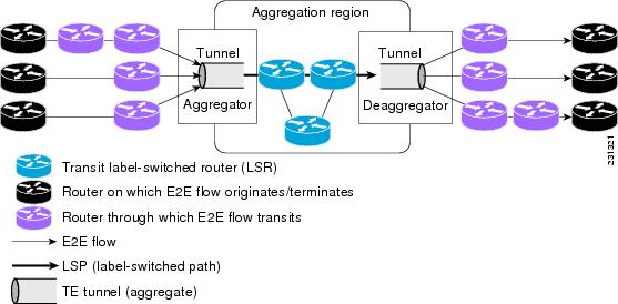
Figure 1 shows three RSVP end-to-end (E2E) flows that originate at routers on the far left, and terminate on routers at the far right. These flows are classic RSVP unicast flows, meaning that RSVP is maintaining a state for each flow. There is nothing special about these flows, except that along their path, these flows encounter an MPLS-TE core, where there is a desire to avoid creating a per-flow RSVP state.
When the E2E flows reach the edge of the MPLS-TE core, they are aggregated onto a TE tunnel. This means that when transiting through the MPLS-TE core, their state is represented by a single state; the TE tunnel is within the aggregation region, and their packets are forwarded (label-switched) by the TE tunnel. For example, if 100 E2E flows traverse the same aggregator and deaggregator, rather than creating 100 RSVP states (PATH and RESV messages) within the aggregation region, a single RSVP-TE state is created, that of the aggregate, which is the TE tunnel, to allocate and maintain the resources used by the 100 E2E flows. In particular, the bandwidth consumed by E2E flows within the core is allocated and maintained in aggregate by the TE tunnel. The bandwidth of each E2E flow is normally admitted into the TE tunnel at the headend, just as any E2E flow's bandwidth is admitted onto an outbound link in the absence of aggregation.
Benefits of MPLS TE—Tunnel-Based Admission Control (TBAC)
To understand the benefits of TBAC, you should be familiar with how Call Admission Control (CAC) works for RSVP and QoS.
Cost Effective
Real-time traffic is very sensitive to loss and delay. CAC avoids QoS degradation for real-time traffic because CAC ensures that the accepted load always matches the current network capacity. As a result, you do not have to overprovision the network to compensate for absolute worst peak traffic or for reduced capacity in case of failure.
Improved Accuracy
CAC uses RSVP signaling, which follows the exact same path as the real-time flow, and routers make a CAC decision at every hop. This ensures that the CAC decision is very accurate and dynamically adjusts to the current conditions such as a reroute or an additional link. Also, RSVP provides an explicit CAC response (admitted or rejected) to the application, so that the application can react appropriately and fast; for example, sending a busy signal for a voice call, rerouting the voice call on an alternate VoIP route, or displaying a message for video on demand.
RSVP and MPLS TE Combined
TBAC allows you to combine the benefits of RSVP with those of MPLS TE. Specifically, you can use MPLS TE inside the network to ensure that the transported traffic can take advantage of Fast Reroute protection (50-millisecond restoration), Constraint Based Routing (CBR), and aggregate bandwidth reservation.
Seamless Deployment
TBAC allows you to deploy IPv4 RSVP without any impact on the MPLS part of the network because IPv4 RSVP is effectively tunneled inside MPLS TE tunnels that operate unchanged as per regular RSVP TE. No upgrade or additional protocol is needed in the MPLS core.
Enhanced Scaling Capability
TBAC aggregates multiple IPv4 RSVP reservations ingressing from the same MPLS TE headend router into a single MPLS TE tunnel and egressing from the same MPLS TE tailend router.
How to Configure MPLS TE—Tunnel-Based Admission Control (TBAC)
This section contains the following procedures:
•![]() Enabling RSVP QoS (required)
Enabling RSVP QoS (required)
•![]() Enabling MPLS TE (required)
Enabling MPLS TE (required)
•![]() Configuring an MPLS TE Tunnel Interface (required)
Configuring an MPLS TE Tunnel Interface (required)
•![]() Configuring RSVP Bandwidth on an MPLS TE Tunnel Interface (required)
Configuring RSVP Bandwidth on an MPLS TE Tunnel Interface (required)
•![]() Verifying the TBAC Configuration (optional)
Verifying the TBAC Configuration (optional)
Enabling RSVP QoS
Perform this task to enable RSVP QoS globally on a router.
SUMMARY STEPS
1. ![]() enable
enable
2. ![]() configure terminal
configure terminal
3. ![]() ip rsvp qos
ip rsvp qos
4. ![]() end
end
DETAILED STEPS
Enabling MPLS TE
Perform this task to enable MPLS TE globally on a router that is running RSVP QoS.
SUMMARY STEPS
1. ![]() enable
enable
2. ![]() configure terminal
configure terminal
3. ![]() mpls traffic-eng tunnels
mpls traffic-eng tunnels
4. ![]() end
end
DETAILED STEPS
Configuring an MPLS TE Tunnel Interface
Perform this task to configure MPLS-TE tunneling on an interface.
Prerequisites
You must configure an MPLS-TE tunnel in your network before you can proceed. For detailed information, see the "MPLS Traffic Engineering (TE)—Automatic Bandwidth Adjustment for TE Tunnels" module.
SUMMARY STEPS
1. ![]() enable
enable
2. ![]() configure terminal
configure terminal
3. ![]() interface tunnel number
interface tunnel number
4. ![]() end
end
DETAILED STEPS
Configuring RSVP Bandwidth on an MPLS TE Tunnel Interface
Perform this task to configure RSVP bandwidth on the MPLS TE tunnel interface that you are using for the aggregation.
SUMMARY STEPS
1. ![]() enable
enable
2. ![]() configure terminal
configure terminal
3. ![]() interface tunnel number
interface tunnel number
4. ![]() ip rsvp bandwidth [interface-kbps] [single-flow-kbps]
ip rsvp bandwidth [interface-kbps] [single-flow-kbps]
5. ![]() end
end
DETAILED STEPS
Verifying the TBAC Configuration

Note ![]() You can use the following show commands in user EXEC or privileged EXEC mode.
You can use the following show commands in user EXEC or privileged EXEC mode.
SUMMARY STEPS
1. ![]() enable
enable
2. ![]() show ip rsvp [atm-peak-rate-limit | counters | host | installed | interface | listeners | neighbor | policy | precedence | request | reservation | sbm | sender | signalling | tos]
show ip rsvp [atm-peak-rate-limit | counters |
host | installed | interface | listeners |
neighbor | policy | precedence | request |
reservation | sbm | sender | signalling | tos]
3. ![]() show ip rsvp reservation [detail] [filter [destination ip-address | hostname] [dst-port port-number] [source ip-address | hostname] [src-port port-number]]
show ip rsvp reservation [detail] [filter
[destination ip-address | hostname] [dst-port
port-number] [source ip-address | hostname]
[src-port port-number]]
4. ![]() show ip rsvp sender [detail] [filter [destination ip-address | hostname] [dst-port port-number] [source ip-address | hostname] [src-port port-number]]
show ip rsvp sender [detail] [filter
[destination ip-address | hostname] [dst-port
port-number] [source ip-address | hostname]
[src-port port-number]]
5. ![]() show mpls traffic-eng link-management bandwidth-allocation [interface-name | summary [interface-name]]
show mpls traffic-eng link-management bandwidth-allocation [interface-name | summary [interface-name]]
6. ![]() exit
exit
DETAILED STEPS
Configuration Examples for MPLS TE—Tunnel-Based Admission Control (TBAC)
•![]() Example: Configuring RSVP Local Policy on a Tunnel Interface
Example: Configuring RSVP Local Policy on a Tunnel Interface
•![]() Example: Verifying the TBAC Configuration
Example: Verifying the TBAC Configuration
Example: Configuring TBAC
Note ![]() You must have an MPLS TE tunnel already configured in your network. For detailed information, see the "MPLS Traffic Engineering (TE)—Automatic Bandwidth Adjustment for TE Tunnels" module.
You must have an MPLS TE tunnel already configured in your network. For detailed information, see the "MPLS Traffic Engineering (TE)—Automatic Bandwidth Adjustment for TE Tunnels" module.
The following example enables RSVP and MPLS TE globally on a router and then configures a tunnel interface and bandwidth of 7500 kbps on the tunnel interface traversed by the RSVP flows:
Router# configure terminal
Enter configuration commands, one per line. End with CNTL/Z.
Router(config)# ip rsvp qos
Router(config)# mpls traffic-eng tunnels
Router(config)# interface tunnel1
Router(config-if)# ip rsvp bandwidth 7500
Router(config-if)# end
Example: Configuring RSVP Local Policy on a Tunnel Interface
The following example configures an RSVP default local policy on a tunnel interface:
Router# configure terminal
Enter configuration commands, one per line. End with CNTL/Z.
Router(config)# interface tunnel1
Router(config-if)# ip rsvp policy local default
Router(config-rsvp-local-if-policy)# max bandwidth single 10
Router(config-rsvp-local-if-policy)# forward all
Router(config-rsvp-local-if-policy)# end
Example: Verifying the TBAC Configuration
Figure 2 shows a network in which TBAC is configured.
Figure 2 Sample TBAC Network
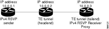
The following example verifies that RSVP and MPLS TE are enabled and coexist on the headend router (10.0.0.2 in Figure 2):
Router# show ip rsvp
RSVP: enabled (on 3 interface(s))
RSVP QoS enabled <-------
MPLS/TE signalling enabled <------
Signalling:
Refresh interval (msec): 30000
Refresh misses: 4
...
The following example verifies that RSVP and MPLS TE are enabled and coexist on the tailend router (10.0.0.3 in Figure 2):
Router# show ip rsvp
RSVP: enabled (on 3 interface(s))
RSVP QoS enabled <-------
MPLS/TE signalling enabled <------
Signalling:
Refresh interval (msec): 30000
Refresh misses: 4
...
The following examples verify that an IPv4 flow is traveling through a TE tunnel (a label-switched path [LSP]) on the headend router (10.0.0.2 in Figure 2):
Router# show ip rsvp sender
To From Pro DPort Sport Prev Hop I/F BPS
10.0.0.3 10.0.0.1 UDP 2 2 10.0.0.1 Et0/0 10K <-- IPv4 flow
10.0.0.3 10.0.0.2 0 1 11 none none 100K <-- TE tunnel
Router# show ip rsvp reservation
To From Pro DPort Sport Next Hop I/F Fi Serv BPS
10.0.0.3 10.0.0.1 UDP 2 2 10.0.0.3 Tu1 SE RATE 10K <-- IPv4 flow
10.0.0.3 10.0.0.2 0 1 11 10.1.0.2 Et1/0 SE LOAD 100K <-- TE tunnel
The following examples verify that an IPv4 flow is traveling through a TE tunnel (LSP) on the tailend router (10.0.0.3 in Figure 2):
Router# show ip rsvp sender
To From Pro DPort Sport Prev Hop I/F BPS
10.0.0.3 10.0.0.1 UDP 2 2 10.0.0.2 Et1/0 10K <-- IPv4 flow
10.0.0.3 10.0.0.2 0 1 11 10.1.0.1 Et1/0 100K <-- TE tunnel
Router# show ip rsvp reservation
To From Pro DPort Sport Next Hop I/F Fi Serv BPS
10.0.0.3 10.0.0.1 UDP 2 2 none none SE RATE 10K <-- IPv4 flow
10.0.0.3 10.0.0.2 0 1 11 none none SE LOAD 100K <-- TE tunnel
The following examples display detailed information about the IPv4 flow and the TE tunnel (LSP) on the headend router (10.0.0.2 in Figure 2):
Router# show ip rsvp sender detail
PATH: <----------------------------------------------- IPv4 flow information begins here.
Destination 10.0.0.3, Protocol_Id 17, Don't Police , DstPort 2
Sender address: 10.0.0.1, port: 2
Path refreshes:
arriving: from PHOP 10.0.0.10 on Et0/0 every 30000 msecs. Timeout in 189 sec
Traffic params - Rate: 10K bits/sec, Max. burst: 10K bytes
Min Policed Unit: 0 bytes, Max Pkt Size 2147483647 bytes
Path ID handle: 02000412.
Incoming policy: Accepted. Policy source(s): Default
Status:
  Output on Tunnel1, out of band. Policy status: Forwarding. Handle: 0800040E <--- TE
tunnel verified
Policy source(s): Default
Path FLR: Never repaired
PATH: <------------------------------------------------ TE tunnel information begins here.
Tun Dest: 10.0.0.3 Tun ID: 1 Ext Tun ID: 10.0.0.2
Tun Sender: 10.0.0.2 LSP ID: 11
Path refreshes:
sent: to NHOP 10.1.0.2 on Ethernet1/0
...
Router# show ip rsvp reservation detail
RSVP Reservation. Destination is 10.0.0.3, Source is 10.0.0.1,<--- IPv4 flow information
begins here.
Protocol is UDP, Destination port is 2, Source port is 2
Next Hop: 10.0.0.3 on Tunnel1, out of band <-------------------- TE tunnel verified
Reservation Style is Shared-Explicit, QoS Service is Guaranteed-Rate
...
Reservation: <--------------------------------------- TE Tunnel information begins here.
Tun Dest: 10.0.0.3 Tun ID: 1 Ext Tun ID: 10.0.0.2
Tun Sender: 10.0.0.2 LSP ID: 11
Next Hop: 10.1.0.2 on Ethernet1/0
Label: 0 (outgoing)
Reservation Style is Shared-Explicit, QoS Service is Controlled-Load
...
Router# show ip rsvp installed detail
RSVP: Ethernet0/0 has no installed reservations
RSVP: Ethernet1/0 has the following installed reservations
RSVP Reservation. Destination is 10.0.0.3. Source is 10.0.0.2,
Protocol is 0 , Destination port is 1, Source port is 11
Traffic Control ID handle: 03000405
Created: 04:46:55 EST Fri Oct 26 2007 <------ IPv4 flow information
Admitted flowspec:
Reserved bandwidth: 100K bits/sec, Maximum burst: 1K bytes, Peak rate: 100K bits/sec
Min Policed Unit: 0 bytes, Max Pkt Size: 1500 bytes
Resource provider for this flow: None
...
RSVP: Tunnel1 has the following installed reservations <------ TE tunnel verified
RSVP Reservation. Destination is 10.0.0.3. Source is 10.0.0.1,
Protocol is UDP, Destination port is 2, Source port is 2
Traffic Control ID handle: 01000415
Created: 04:57:07 EST Fri Oct 26 2007 <----- IPv4 flow information
Admitted flowspec:
Reserved bandwidth: 10K bits/sec, Maximum burst: 10K bytes, Peak rate: 10K bits/sec
Min Policed Unit: 0 bytes, Max Pkt Size: 0 bytes
Resource provider for this flow: None
...
Router# show ip rsvp interface detail
Et0/0:
RSVP: Enabled
Interface State: Up
Bandwidth:
Curr allocated: 0 bits/sec
Max. allowed (total): 3M bits/sec
Max. allowed (per flow): 3M bits/sec
...
Et1/0:
RSVP: Enabled
Interface State: Up
Bandwidth:
Curr allocated: 0 bits/sec
Max. allowed (total): 3M bits/sec
Max. allowed (per flow): 3M bits/sec
...
Tu1: <--------------------------------- TE tunnel information begins here.
RSVP: Enabled
RSVP aggregation over MPLS TE: Enabled
Interface State: Up
Bandwidth:
Curr allocated: 20K bits/sec
Max. allowed (total): 3M bits/sec
Max. allowed (per flow): 3M bits/sec
...
The following examples display detailed information about the IPv4 flow and the TE tunnel (LSP) on the tailend router (10.0.0.3 in Figure 2):
Router# show ip rsvp sender detail
PATH: <----------------------------------------------- IPv4 flow information begins here.
Destination 10.0.0.3, Protocol_Id 17, Don't Police , DstPort 2
Sender address: 10.0.0.1, port: 2
Path refreshes:
    arriving: from PHOP 10.0.0.2 on Et1/0 every 30000 msecs, out of band. Timeout in 188
sec
Traffic params - Rate: 10K bits/sec, Max. burst: 10K bytes
Min Policed Unit: 0 bytes, Max Pkt Size 2147483647 bytes
...
PATH: <------------------------------------------------ TE tunnel information begins here.
Tun Dest: 10.0.0.3 Tun ID: 1 Ext Tun ID: 10.0.0.2
Tun Sender: 10.0.0.2 LSP ID: 11
Path refreshes:
arriving: from PHOP 10.1.0.1 on Et1/0 every 30000 msecs. Timeout in 202 sec
...
Router# show ip rsvp reservation detail
RSVP Reservation. Destination is 10.0.0.3, Source is 10.0.0.1, <--- IPv4 flow information
begins here.
Protocol is UDP, Destination port is 2, Source port is 2
Next Hop: none
Reservation Style is Shared-Explicit, QoS Service is Guaranteed-Rate
...
Reservation: <--------------------------------------- TE tunnel information begins here.
Tun Dest: 10.0.0.3 Tun ID: 1 Ext Tun ID: 10.0.0.2
Tun Sender: 10.0.0.2 LSP ID: 11
Next Hop: none
Label: 1 (outgoing)
Reservation Style is Shared-Explicit, QoS Service is Controlled-Load
...
Router# show ip rsvp request detail
RSVP Reservation. Destination is 10.0.0.3, Source is 10.0.0.1,
Protocol is UDP, Destination port is 2, Source port is 2
Prev Hop: 10.0.0.2 on Ethernet1/0, out of band <-------------- TE tunnel verified
Reservation Style is Shared-Explicit, QoS Service is Guaranteed-Rate
Average Bitrate is 10K bits/sec, Maximum Burst is 10K bytes
...
Request: <------------------------------------ TE tunnel information begins here.
Tun Dest: 10.0.0.3 Tun ID: 1 Ext Tun ID: 10.0.0.2
Tun Sender: 10.0.0.2 LSP ID: 11
Prev Hop: 10.1.0.1 on Ethernet1/0
Label: 0 (incoming)
Reservation Style is Shared-Explicit, QoS Service is Controlled-Load
...
Example: Verifying the RSVP Local Policy Configuration
The following example verifies that a default local policy has been configured on tunnel interface 1:
Router# show run interface tunnnel 1
Building configuration...
Current configuration : 419 bytes
!
interface Tunnel1
bandwidth 3000
ip unnumbered Loopback0
tunnel destination 10.0.0.3
tunnel mode mpls traffic-eng
tunnel mpls traffic-eng autoroute announce
tunnel mpls traffic-eng priority 1 1
tunnel mpls traffic-eng bandwidth 100
tunnel mpls traffic-eng path-option 1 dynamic
tunnel mpls traffic-eng fast-reroute
ip rsvp policy local default <---------------- Local policy information begins here.
max bandwidth single 10
forward all
ip rsvp bandwidth 3000
end
The following example provides additional information about the default local policy configured on
tunnel interface 1:
Router# show ip rsvp policy local detail
Tunnel1:
Default policy:
Preemption Scope: Unrestricted.
Local Override: Disabled.
Fast ReRoute: Accept.
Handle: BC000413.
Accept Forward
Path: Yes Yes
Resv: Yes Yes
PathError: Yes Yes
ResvError: Yes Yes
Setup Priority Hold Priority
TE: N/A N/A
Non-TE: N/A N/A
Current Limit
Senders: 0 N/A
Receivers: 1 N/A
Conversations: 1 N/A
Group bandwidth (bps): 10K N/A
Per-flow b/w (bps): N/A 10K
Generic policy settings:
Default policy: Accept all
Preemption: Disabled
Additional References
The following sections provide references related to the MPLS TE Tunnel-Based Admission Control (TBAC) feature.
Related Documents
Standards
|
|
|
|---|---|
No new or modified standards are supported by this feature, and support for existing standards has not been modified by this feature. |
— |
MIBs
RFCs
Technical Assistance
Command Reference
The following commands are introduced or modified in the feature or features documented in this module. For information about these commands, see the Cisco IOS Quality of Service Solutions Command Reference at http://www.cisco.com/en/US/docs/ios/qos/command/reference/qos_book.html. For information about all Cisco IOS commands, use the Command Lookup Tool at http://tools.cisco.com/Support/CLILookup or a Cisco IOS master commands list.
•![]() ip rsvp qos
ip rsvp qos
•![]() show ip rsvp
show ip rsvp
•![]() show ip rsvp reservation
show ip rsvp reservation
•![]() show ip rsvp sender
show ip rsvp sender
•![]() show mpls traffic-eng link-management bandwidth-allocation
show mpls traffic-eng link-management bandwidth-allocation
Feature Information for MPLS TE—Tunnel-Based Admission Control (TBAC)
Table 1 lists the release history for this feature.
Not all commands may be available in your Cisco IOS software release. For release information about a specific command, see the command reference documentation.
Use Cisco Feature Navigator to find information about platform support and software image support. Cisco Feature Navigator enables you to determine which Cisco IOS and Catalyst OS software images support a specific software release, feature set, or platform. To access Cisco Feature Navigator, go to http://www.cisco.com/go/cfn. An account on Cisco.com is not required.
Note ![]() Table 1 lists only the Cisco IOS software release that introduced support for a given feature in a given Cisco IOS software release train. Unless noted otherwise, subsequent releases of that Cisco IOS software release train also support that feature.
Table 1 lists only the Cisco IOS software release that introduced support for a given feature in a given Cisco IOS software release train. Unless noted otherwise, subsequent releases of that Cisco IOS software release train also support that feature.
Glossary
admission control—The process by which an RSVP reservation is accepted or rejected on the basis of end-to-end available network resources.
aggregate—An RSVP flow that represents multiple E2E flows; for example, an MPLS-TE tunnel may be an aggregate for many E2E flows.
aggregation region—A area where E2E flows are represented by aggregate flows, with aggregators and deaggregators at the edge; for example, an MPLS-TE core, where TE tunnels are aggregates for E2E flows. An aggregation region contains a connected set of nodes that are capable of performing RSVP aggregation.
aggregator—The router that processes the E2E PATH message as it enters the aggregation region. This router is also called the TE tunnel headend router; it forwards the message from an exterior interface to an interior interface.
bandwidth—The difference between the highest and lowest frequencies available for network signals. The term is also used to describe the rated throughput capacity of a given network medium or protocol.
deaggregator—The router that processes the E2E PATH message as it leaves the aggregation region. This router is also called the TE tunnel tailend router; it forwards the message from an interior interface to an exterior interface.
E2E—end-to-end. An RSVP flow that crosses an aggregation region and whose state is represented in aggregate within this region; for example, a classic RSVP unicast flow that crosses an MPLS-TE core.
LSP—label-switched path. A configured connection between two routers, in which label switching is used to carry the packets. The purpose of an LSP is to carry data packets.
MPLS—Multiprotocol Label Switching. Packet-forwarding technology, used in the network core, that applies data link layer labels to tell switching nodes how to forward data, resulting in faster and more scalable forwarding than network layer routing normally can do.
QoS—quality of service. A measure of performance for a transmission system that reflects its transmission quality and service availability.
RSVP—Resource Reservation Protocol. A protocol that supports the reservation of resources across an IP network. Applications that run on IP end systems can use RSVP to indicate to other nodes the nature (bandwidth, jitter, maximum burst, and so on) of the packet streams that they want to receive.
state—Information that a router must maintain about each LSP. The information is used for rerouting tunnels.
TE—traffic engineering. The techniques and processes that are used to cause routed traffic to travel through the network on a path other than the one that would have been chosen if standard routing methods had been used.
tunnel—Secure communications path between two peers, such as two routers.
 Feedback