Downloads |
 Feedback Feedback
|
Table Of Contents
Supported Cisco AccessPath Stack Types
Configure Stack General Information
Configure Stack Trunk and Name Server Information
Configure Stack Trunk Interface
Configure Stack Network Management
Configure Stack Security Server
Configuring System Controllers
Configure System Controller General Information
Configure System Controller Name Server Information
Configure System Controller Trunk Interface
Configure System Controller Network Management
Configure System Controller Security
Configure System Controller Security Server
Configure System Controller Access and Template
Schedule System Controller Download
Scheduling System Controller Deletion
Configuring Containers
This chapter provides information about configuring containers in Cisco Access Manager (CAM). Containers logically organize devices that are managed in CAM. You can configure three container types as described in the following sections:
•
Configuring System Controllers
Groups are the highest level of containers. All stacks and System Controllers you configure in CAM belong to a group. If you do not configure a stack or System Controller to belong to a user-defined group, it will automatically belong to the default group, CAMROOT.
Stacks and System Controllers are hierarchical equivalents. They are the logical and physical containers of shelves. Currently, you can configure the shelves in stacks to be a combination of Cisco AS5300, Cisco 7206, Catalyst 5002, and Cisco 3640 devices and you can configure shelves in System Controllers to be Cisco AS5800 devices.
For information about configuring shelves for stacks and System Controllers, see Chapter 5, "."
Tips
To configure using CAM, you must supply information for all fields presented in bold in each dialog box of the configuration screens. Pull-down menus and data-entry fields will be disabled if your previous configuration choices make them unnecessary.
Configuring Groups
Groups provide a method for logically organizing your devices into generic domains. A group can be made up of devices such as stacks, System Controllers, and even other groups. The group can represent geographical regions, classes of users, or some other classification that helps you to categorize your devices.
When configure a group, it belongs to either CAMROOT (the default group) or to a user-defined group.
To configure a group, complete the tasks in the following sections. All three tasks are optional.
Creating a Group
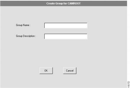
You can create as many user-defined groups as you need. The CAMROOT group is automatically created when you start CAM. The dialog box that appears allows you to create a group. (See .)
Figure 4-1 Create Group Dialog Box
To create a group:
1
Select the CAMROOT group or any user-defined group.
The group to which you want to add the new group. The group you add is subordinate to the group you select in the Device Tree View.
2
Click Configure.
The Task Selection bar displays all the configuration tasks CAM can perform for groups.
3
Click Create Group.
4
Enter the group name.
Define a name that easily identifies the generic domain. For example, if the group logically organizes your devices by geographical region, use the region as its name. The group name can be up to 64 characters in length. This name is stored in the CAM server database.
5
Enter a group description.
An optional description to provide useful information about the group. You can specify up to 64 characters.
6
Click OK.
You have successfully created a group. CAM displays the newly created group in the Device Tree View. You can now add a stack, System Controller, or another group to it. For more information about how to do this, see the "Configuring Stacks" section, "Configuring System Controllers" section, or repeat these steps.
Modifying a Group
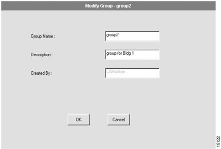
You can modify a user-defined group, but not the default group CAMROOT. The dialog box that appears allows you to modify a group. (See .)
Figure 4-2 Modify Group Dialog Box
To modify a group:
1
Select any user-defined group in the Device Tree View.
The group you want to modify.
2
Click Configure.
The Task Selection bar displays all the configure tasks CAM can perform for groups.
3
Click Modify.
4
Enter new information in the Group Name and/or Description field.
The group name and group description can each be up to 64 characters in length.
5
Click OK.
You have successfully modified a group. If the change is not reflected in the Device Tree View, click Refresh. See "Refreshing Your System" section for more information.
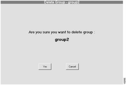
Deleting a Group
You can delete any user-defined group that is empty. This means you can only delete a group after all the stacks in the group are deleted. You cannot delete the default group CAMROOT. The dialog box that appears allows you to delete a group. (See .)
Figure 4-3 Delete Group Dialog Box
To delete a group:
1
Select a user-defined group in the Device Tree View.
The group you want to delete.
2
Click Configure.
The Task Selection bar displays all the configure tasks CAM can perform for groups.The Delete button is activated only when all stacks in the group are deleted first.
3
Click Delete.
4
Click Yes.
You have successfully deleted a group. CAM removes it from the Device Tree View. If the change is not reflected in the Device Tree View, click Refresh. See "Refreshing Your System" section for more information.
Configuring Stacks
Stacks are containers for shelves. The devices (switch, number of NAS(s), and number of Cisco 7206s) contained in the stack determine the stack type. CAM supports several stack types, which are listed in the "Supported Cisco AccessPath Stack Types" section.
In addition, the configuration parameters for the stack are interdependent. CAM shows the valid values from which you can make your choice. These parameter dependencies are listed in the "Creating a Stack" section.
To configure a stack, complete the tasks in the following sections. The first two tasks are required; the third and fourth tasks are optional.
•
Supported Cisco AccessPath Stack Types
CAM supports several stack types. The following table lists the CAM-supported stack types and their components:
Creating a Stack
The procedure for creating a stack should be thought of as a series of planning sheets, with which you design the stack. This procedure creates a container into which you must then create all of the individual shelves as described in Chapter 5, "."
During the stack creation or stack modification procedure, CAM steps you through a series of dialog boxes in which you provide configuration information. Several dialog boxes are common to both the stack creation and stack modification procedures. At these dialog boxes, you can:
1
2
3
5
Several parameters that you configure during the stack creation and stack modification procedures are interdependent. This means that some selections you make on one configuration dialog box can determine the values from which you can select later on (including if the parameter even applies to the type of stack you have configured). The following table provides a matrix that helps you to understand the stack parameter dependencies.
Table 4-2 Stack Parameter Dependencies
Type
Switch
Type
(E1-R2 only)PRI
T1 or E1
primary-5ess
primary-4ess
primary-dms100
primary-net5
primary-ntt
primary-ts014-
-
multichannel only
single channel only
single and multichannelsCE1
E1
-
p7
r2-analog
r2-digital
r2-pulse(See the "Configure Stack Trunk Interface" section for a list of countries.)
-
CT1
T1
-
sas-loop-start
sas-ground-start
fxs-loop-start
fxs-ground-start
e&m-fgb
e&m-fgd
e&m-immediatestar-
-
PRI and CE1
E1
primary-5ess
primary-4ess
primary-dms100
primary-net5
primary-ntt
primary-ts014p7
r2-analog
r2-digital
r2-pulse(See the "Configure Stack Trunk Interface" section for a list of countries.)
multichannel only
single channel only
single and multi channelsPRI and CT1
T1
primary-5ess
primary-4ess
primary-dms100
primary-net5
primary-ntt
primary-ts014sas-loop-start
sas-ground-start
fxs-loop-start
fxs-ground-start
e&m-fgb
e&m-fgd
e&m-immediatestar-
multichannel only
single channel only
single and multichannels
The procedures for creating and modifying a stack are similar but not identical. For information common to both, continue reading this section. For information specific to modifying a stack, skip to the "Modifying a Stack" section.
To add a stack, follow these steps:
1
Select the CAMROOT group or any user-defined group.
The group to which you want to add a stack. If you do not select a group, the stack is added to CAMROOT.
2
Click Configure.
The Task Selection bar displays all the configuration tasks CAM can perform for groups.
3
Click Create Stack.
Proceed to the "Configure Stack General Information" section.
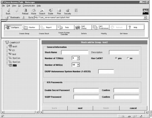
Configure Stack General Information
The first dialog box that appears allows you to configure general information about the stack. (See .)
Figure 4-4 Stack Add for Group Dialog Box (1 of 7)
To configure general information about the stack:
1
Enter a stack name.
The case-sensitive stack group authentication name. It must be unique in the rack.
2
(Optional.) Enter a stack description.
Description cannot exceed 64 characters.
3
Select the number of Cisco 7206(s) in the stack.
Defines the maximum number of Cisco 7206s. For all stack types that use a Catalyst 5000 series Switch Shelf, the maximum is 2. (See "Supported Cisco AccessPath Stack Types" section for details.)
4
Select the number of network access servers (NAS) in the stack.
Defines the maximum number of Access Server Shelves in the stack. The number of Access Server Shelves depends on your configuration. (See "Supported Cisco AccessPath Stack Types" section for details.)
5
Select yes or no.
The Catalyst 5002 is optional depending on your configuration. (See "Supported Cisco AccessPath Stack Types" section for details.)
6
(Modify only.) Select now or later for Config the Stack.
If you are modifying a stack you can choose whether to configure the stack now or later. If you choose later, then you need to schedule the download. (See "Scheduling a Stack Download" section for information.)
7
Enter the EIGRP system number.
The Enhanced Interior Gateway Routing Protocol (EIGRP) Autonomous system number must be a value from 1 to 65535.
8
Enter a Cisco IOS secret password.
The Cisco IOS enable secret password is encrypted so that it cannot be read when crossing a network. After you issue this command, the encryption cannot be reversed. The encrypted version of the password appears in output of the show running-config and show startup-config commands.
The password cannot exceed 25 characters. You must enter the same password in the Confirm field.
9
Enter an SGBP password.
The Stack Group Bidding Protocol (SGBP) password establishes a username-based authentication system; the stack password is used to access the name argument.
The password cannot exceed 25 characters.You must enter the same password in the Confirm field.
10
Click next.
Proceed to the"Configure Stack Trunk and Name Server Information" section.
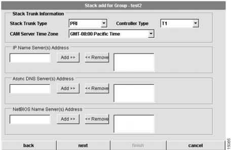
Configure Stack Trunk and Name Server Information
The second dialog box that appears allows you to configure trunk and name server information about the stack. (See .)
Figure 4-5 Stack Add for Group Dialog Box (2 of 7)
To configure trunk and name server information:
1
Select a stack trunk type.
Select the trunk type supported by your service provider. Available choices include:
•
•
•
•
•
2
Select the CAM server time zone.
CAM retrieves the default value for your time zone from your local host. Time zones are expressed relative to Greenwich Mean Time (GMT). Verify that this field has the correct value.
3
Select a stack controller type.
The controller type (T1 or E1) accepts incoming calls and sends outgoing calls through ISDN PRI lines. (For all selections of Stack Trunk Type except PRI, this defaults to the correct selection for your network.)
4
(Optional.) Specify your name server address(es).
Domain name servers resolve host names and IP addresses. You can specify one or more addresses.
To add an address, enter an address in the left box and click the Add button. It displays in the right box. To remove an address, highlight an address in the right box and click the Remove button.
5
(Optional.) Specify your Async DNS server address(es).
This server address enables remote users to gather DNS information transparently as part of the Point-to-Point Protocol (PPP) negotiation. Dial-in clients using PPP applications, such as CiscoRemote and Windows 95, need Domain Name System (DNS) address information as described in RFC 1877.
To add an address, enter an address in the left box and click the Add button. It displays in the right box.To remove an address, highlight an address in the right box and click the Remove button.
6
(Optional.) Specify your NetBIOS name server address(es).
This server address enables remote users to gather NBNS information transparently as part of the PPP negotiation. Dial-in clients using PPP applications, such as CiscoRemote and Windows 95, need NetBIOS name server (NBNS) address information as described in RFC 1877.
To add an address, enter an address in the left box, and click the Add button. It displays in the right box.To remove an address, highlight an address in the right box and click the Remove button.
7
Click next.
Proceed to the "Configure Stack Trunk Interface" section.
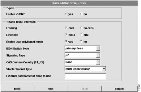
Configure Stack Trunk Interface
The third dialog box that appears allows you to configure trunk interface information for the stack. (See .)
Figure 4-6 Stack Add for Group Dialog Box (3 of 7)
To configure trunk interface information:
1
Select yes or no to enable or disable Virtual Private Dialup Network (VPDN) support.
If you select no, none of the shelves in this stack can support VPDN. Selecting yes allows for a mixed configuration in which some shelves support VPDN and some do not. (You will configure the use of VPDN on a shelf-by-shelf basis when you create the shelves in the stack. See "."
2
Select your framing.
Framing is the type of transmission unit used in the T1 or E1 link. Available choices for Channelized T1 and PRI include:
•
•
•
•
3
Select a linecode.
Linecode is the Variety of Zero Code Suppression used on the link, which in turn affects a number of its characteristics. Available choices for PRI and Channelized T1 include:
•
•
•
4
Select yes or no to enable or disable user privileged mode.
Select yes to enable user privileged mode. Select no allow users to access the EXEC facility and start EXEC sessions. User privileged mode provides read/write privileges, but also allows a user to create and modify other users. The default is yes.
5
Select your ISDN switch type.
ISDN switch type for your T1 or E1 PRI lines. Set this value if you have selected one of the PRI trunk types. You should obtain the correct switch type from your ISDN service provider (telco). Available choices include:
•
•
•
•
•
•
CAM provides your selection to the Access Server Shelves in the stack by default.
6
Select a signaling type.
The Cisco AS5300 stack supports channel associated signaling (CAS) for channelized T1/E1 lines. Set this value if you have selected one of the PRI trunk types.
Typically, all channels of a channelized T1 or E1 line are used for analog calls. However, the Cisco AS5300 stack requires a signal converter to perform conversions between R2 signaling and ear and mouth (E&M) (also called "receive and transmit") signaling. Valid selections for channelized lines include:
•
•
•
•
•
•
•
•
•
•
•
•
•
7
Select a CAS custom country.
Channel associated signaling (CAS). If you have selected E1 R2 signaling, you might need to select a country customization for this signaling. The options include:
•
•
•
•
•
•
•
•
•
•
•
•
•
•
•
•
•
•
•
•
8
Select your stack channel type.
Channel type servicing your T1 PRI or E1 PRI lines. The Channel type can be:
•
•
•
9
Set the external host name for CHAP to use.
Set the Challenge Handshake Authentication Protocol (CHAP) name that the remote users will see when they dial in.
10
Click next.
Proceed to the "Configure Stack Addressing" section.
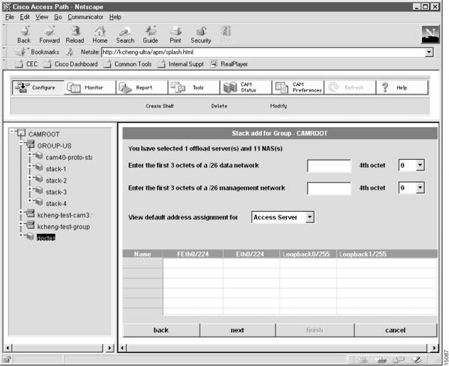
Configure Stack Addressing
The fourth dialog box that appears allows to configure stack addressing information. (See .)
Figure 4-7 Stack Add for Group Dialog Box (4 of 7)
To configure stack addressing information:
1
Enter the first 3 octets of the starting /24 network.
Depending on the Cisco AccessPath system configuration you have selected, this dialog box shows the number of contiguous class C (/24) networks you need. In this field, enter the first 3 octets of the network address for the first class C network. CAM uses this information to create IP addresses for the ports in your Cisco AccessPath system.
2
Enter the first 3 octets of your management network.
In addition to your data network, you need a management network. This network is a /26 network for Cisco AccessPath system stacks.
3
Enter the 4th octet.
Select the 4th octet of the starting class C network address. This affects the address map that applies to your configuration. This value applies only to the /26 management network.
4
(Optional.) Select a shelf type to show address assignment for the shelves in the stack.
Use this pull-down menu to select the shelves for which you want to see the planned IP addressing. Select from the following:
•
•
•
5
Click next.
Proceed to the "Configure Stack Network Management" section.
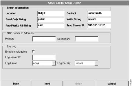
Configure Stack Network Management
The fifth dialog box that appears allows you to configure network management information for the stack. (See .)
Figure 4-8 Stack Add for Group Dialog Box (5 of 7)
To configure network management information:
1
Enter the location of the stack.
The physical location of this Cisco AccessPath system (for example, Bldg. 5).
2
Enter a contact.
The contact person for this Cisco AccessPath system.
3
Enter a read-only string.
The Simple Network Management Protocol (SNMP) read community string.
4
Enter a write string.
The SNMP write community string.
5
Enter a read/write all string.
This SNMP read/write all community string applies only to stacks that include Catalyst 5002. See the "Supported Cisco AccessPath Stack Types" section for the devices that make up your stack.
6
Enter the trap server IP address.
The IP address of trap server host.
7
(Optional.) Configure the primary Network time Protocol (NTP) server and secondary NTP server IP addresses.
The IP address(es) of NTP server(s) synchronize the system clock.
8
(Optional.) Choose to enable or disable syslogging.
When this box is checked, syslogging is enabled, and a log of system activity is created.
9
(Optional.) Configure the log server IP address.
If you enable syslogging, you must specify the IP address of syslog server host.
10
(Optional.) Configure the log level.
You must select a level of logging information. Available levels include:
•
•
•
•
•
•
•
•
11
(Optional.) Select a syslog facility.
This is syslog facility. Available values include:
•
•
•
•
•
•
•
•
•
•
•
•
•
•
•
•
•
•
•
•
•
•
•
•
12
Click next.
Proceed to the "Configure Stack Security" section.
Configure Stack Security
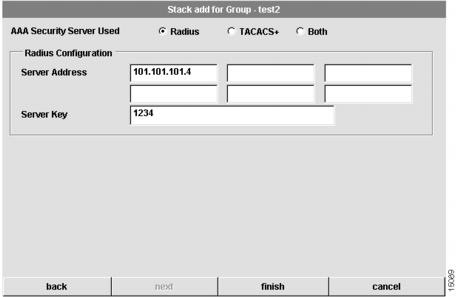
The sixth dialog box that appears allows you to configure security information for the stack. CAM supports two types of authentication, authorization, and accounting (AAA) security servers. The dialog box that displays depends on the type of AAA server you select. (See through .) If you select a Remote Access Dial-In User Service (RADIUS) security server, the following dialog box appears:
Figure 4-9 Stack Add for Group Dialog Box (6 of 7—RADIUS only)
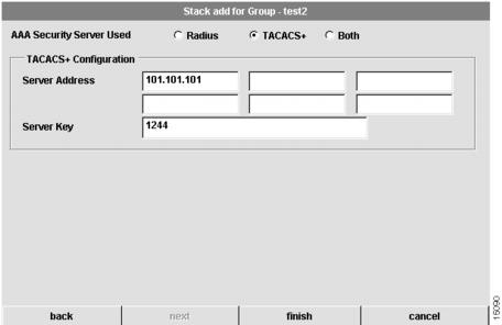
If you select a Terminal Access Controller Access Control System (TACACS+) security server, the following dialog box appears:
Figure 4-10 Stack Add for Group Dialog Box (6 of 7—TACACS+ only)
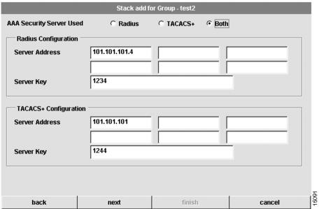
If you select Both, the following dialog box appears:
Figure 4-11 Stack Add for Group Dialog Box (6 of 7—Both)
To configure security information for the stack:
1
Configure the type of AAA security server used.
You can select RADIUS, TACACS+, or both as your remote security database. If you select RADIUS, see . If you select TACACS+, see . If you select Both, see .
2
Configure the security server IP address.
IP address of the remote RADIUS or TACACS+ server host. This host is typically a UNIX system running RADIUS or TACACS+ software.
3
Configure a server key.
Shared secret text string used between the Access Server Shelf and the RADIUS or TACACS+ server. The Access Server Shelf and RADIUS or TACACS+ server use this text string to encrypt passwords and exchange responses.
4
Click next if you selected Both in Step 1.
Proceed to the "Configure Stack Security Server" section.
5
Click finish if you selected RADIUS or TACACS+ only.
You have successfully added or modified a stack.
Proceed to the "Shelf Configuration for Stacks" section.If you have selected Both in Step 1, proceed to "Scheduling a Stack Download" section.
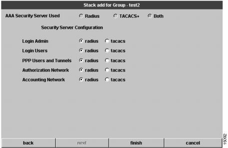
Configure Stack Security Server
This dialog box only appears if you have selected Both (TACACS+ and RADIUS) as the AAA security server used. (See .)
You must configure advanced security features, such as authentication method lists, which you then apply to lines and interfaces. These authentication method lists are security profiles that indicate the protocol AppleTalk Remote Access Protocol (ARAP) or PPP, or login and authentication method (TACACS+, RADIUS, or local authentication).
Figure 4-12 Stack Add for Group Dialog Box (7 of 7)
To configure security information for the stack:
1
Configure advanced security features.
At this dialog box you can specify whether TACACS+ or RADIUS provide authentication for the following services:
•
•
•
•
•
2
Click finish.
You have finished everything but the downloading of the configuration.
Proceed to the "Shelf Configuration for Stacks" section.
Modifying a Stack
The procedure for modifying a stack actually alters the configurations of the shelves in the stack instead of simply designing the stack through a series of planning sheets. In most cases, by the time you modify a stack, you probably have already created shelves and configured them. If the shelves in a stack were configured (that is, if CAM downloaded the configurations to the shelves in the stack), modifying a stack automatically updates all of the shelf configurations. The procedures to modify stacks and shelves are similar to those to create the stacks and shelves.
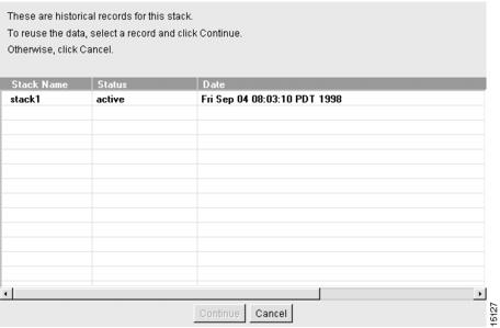
When you modify a stack, CAM creates a new configuration record and saves it in the database. CAM lists the contents of that record in the Modify Stack—Historical Records dialog box. (See .) At the same time, CAM creates a new configuration record for each shelf in the stack, saves it to the database, and lists the record in their respective Modify Shelf—Historical Record dialog boxes. The stack determines the shelves' status.
By listing all the records that have been created for the stack, you can select previous configurations or the most recent configuration record to use for your system.
Figure 4-13 Modify Stack—Historical Records Dialog Box
The Modify Stack—Historical Records dialog box lists the following the stack record fields:
During the stack modification procedure, CAM steps you through a series of dialog boxes in which you can provide new configuration information. Several dialog boxes are common to both the stack modification and stack creation procedures. At these dialog boxes, you can:
1
2
3
4
5
6
Note
To modify a stack:
1
Select a stack from the Device Tree View.
The stack you want to modify.
2
Click Configure.
The Task Selection bar displays all the configuration tasks CAM can perform for stacks.
3
Click Modify.
A dialog box containing historical records for the selected stack appears. (See .)
4
Select a stack record.
The stack record you want to modify.
5
Click Continue.
Proceed to the "Configure Stack General Information" section to continue the stack modification procedure.
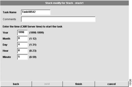
Scheduling a Stack Download
When you modify a stack, you can choose whether to configure the stack now or later. If you choose later, you are able to schedule the download at the last dialog box of the stack modification procedure. (See .)
Figure 4-14 Stack Modify for Stack—Schedule Task Dialog Box
To schedule a stack download, follow these steps:
1
Enter a task name.
Enter a task name for the scheduled stack configuration procedure. This task can be viewed from the Task Manager in the Tools menu.
2
(Optional.) Enter comments.
Enter any comments in the comments field.
3
Enter the time on the server when the download task should start.
Use these fields to schedule the job. The download will occur when the server time matches the time you configure.
•
•
•
•
•
4
Click finish.
You have scheduled the stack download task. You can manage this task through the Task Manager as described in the "Using the Task Manager" section on page 8-59. After a scheduled task executes, you might need to refresh your system. See the "Refreshing Your System" section for details.
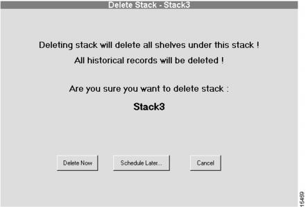
Deleting a Stack
CautionWhen a stack is deleted, all related information about the stack and its shelves is deleted from the database. Only use this procedure if you are sure you want to delete the stack, its shelves, and its historical data. (See .)
Figure 4-15 Delete Stack Dialog Box
To delete a stack:
1
Select a stack from the Device Tree View.
The stack you want to delete.
2
Click Configure.
The Task Selection bar displays all the configuration tasks CAM can perform for the stack.
3
Click Delete Now, Schedule Later..., or Cancel.
If this is the correct stack, and you are sure you want to delete it and all of its historical data, click Delete Now or Schedule Later.... Otherwise, click Cancel.
If you click Schedule Later..., continue with the "Scheduling Stack Deletion" section
Scheduling Stack Deletion
Scheduling the stack deletion is the final step in the delete stack procedure. (See .)
Figure 4-16 Delete Stack Schedule Dialog Box
To schedule stack deletion:
1
Enter a task name.
Enter a task name for the scheduled stack deletion procedure. This task can be viewed from the Task Manager in the Tools menu.
2
(Optional.) Enter comments.
Enter any comments in the comments field.
3
Enter the time on the server when the deletion task should start.
Use these fields to schedule the job. The deletion will occur when the server time matches the time you configure.
•
•
•
•
•
4
Click finish.
You have scheduled the stack delete task. You can manage this task through the Task Manager as described in the "Using the Task Manager" section on page 8-59. After a scheduled task executes, you might need to refresh
your system. See the "Refreshing Your System" section for details.
Configuring System Controllers
System Controllers provide local gathering and monitoring functions for dial shelves and router shelves within a single point of presence (POP).
To configure a System Controller, complete the following tasks in the following sections. The first two tasks are required; the third and fourth tasks are optional.
•
•
Creating a System Controller
During the System Controller creation or System Controller modification procedure, CAM steps you through a series of dialog boxes in which you provide configuration information. At these dialog boxes, you can:
1
2
3
4
5
6
7
8
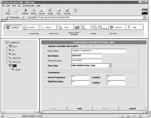
Configure System Controller General Information
The first dialog box that appears allows you to configure general information about the System Controller. (See .)
Figure 4-17 Create System Controller for Group Dialog Box (1 of 8)
To configure general information about the System Controller:
1
(Optional.) Enter a System Controller description.
Description cannot exceed 64 characters.
2
Enter a host name.
The case-sensitive host name group. It must be unique in the rack.
3
(Optional.) Enter the System Controller serial number.
The serial number uniquely identifies the System Controller hardware unit. The serial number can contain up to 32 characters.
4
Select the CAM server time zone.
CAM retrieves the default value for your time zone from your local host. Time zones are expressed relative to Greenwich Mean Time (GMT). Verify that this field has the correct value.
5
Enter a Cisco IOS secret password.
The Cisco IOS enable secret password is encrypted so that it cannot be read when crossing a network. After you issue this command, the encryption cannot be reversed. The encrypted version of the password appears in output of the show running-config and show startup-config commands.
The password cannot exceed 25 characters. You must enter the same password in the Confirm field.
6
Enter a Shelf discovery password.
The System Controller uses this password to discover the shelves it manages. This defines the periodic handshake between the System Controller and the shelves. This password must be the same on both the shelf and System Controller.
The password cannot exceed 25 characters.You must enter the same password in the Confirm field.
7
Click next.
Proceed to the "Configure System Controller Name Server Information" section.
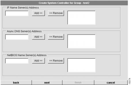
Configure System Controller Name Server Information
The second dialog box that appears allows you to configure name server information for the System Controller. (See .)
Figure 4-18 Create System Controller for Group Dialog Box (2 of 8)
To configure System Controller name server information, follow these steps:
1
(Optional.) Specify your name server address(es).
Domain name servers resolve host names and IP addresses. You can specify one or more addresses.
To add an address, enter an address in the left box and click the Add button. It displays in the right box. To remove an address, highlight an address in the right box and click the Remove button.
2
(Optional.) Specify your Async DNS server address(es).
Server address enables remote users to gather DNS information transparently as part of the Point-to-Point Protocol (PPP) negotiation. Dial-in clients using PPP applications such as CiscoRemote and Windows 95 need Domain Name System (DNS) address information as described in RFC 1877.
To add an address, enter an address in the left box and click the Add button. It displays in the right box.To remove an address, highlight an address in the right box and click the Remove button.
3
(Optional.) Specify your NetBIOS name server address(es).
Server address enables remote users to gather NBNS information transparently as part of the PPP negotiation. Dial-in clients using PPP applications such as CiscoRemote and Windows 95 need NetBIOS name server (NBNS) address information as described in RFC 1877.
To add an address, enter an address in the left box and click the Add button. It displays in the right box.To remove an address, highlight an address in the right box and click the Remove button.
4
Click next.
Proceed to the "Configure System Controller Trunk Interface" section.
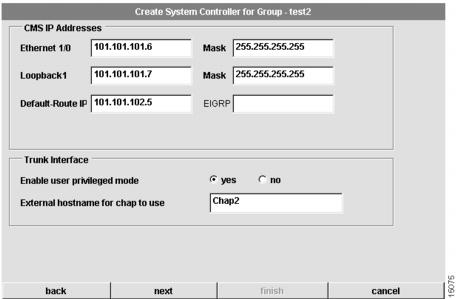
Configure System Controller Trunk Interface
The third dialog box that appears allows you to configure trunk interface information for the System Controller. (See .)
Figure 4-19 Create System Controller for Group Dialog Box (3 of 8)
To configure System Controller trunk interface information:
1
Enter the Ethernet I/O IP Address.
An IP address in dotted decimal format.
2
Enter the Loopback1 IP address.
An IP address in dotted decimal format.
3
Enter the Default-Route IP address.
An IP address in dotted decimal format.
4
Enter the mask for the Ethernet I/O and Loopback1.
A mask, typically 255.255.255.255 in dotted decimal format.
5
(Optional.) Enter EIGRP network number.
We recommend that you specify a routing protocol for the System Controller and its shelves. If you specify an EIGRP network number, CAM automatically configures the System controller and all of its shelves to run EIGRP. If you do not specify EIGRP as the routing protocol for the System Controller and its shelves, you must manually configure the routing protocol for the System Controller and its shelves.
6
Select yes or no to enable or disable user privileged mode.
Select yes to enable user privileged mode. Select no to refuse user privileged mode to all but CAM administrators. User privileged mode provides read/write privileges but also allows a user to create and modify other users.
7
Set the external host name for CHAP to use.
Set the Challenge Handshake Authentication Protocol (CHAP) name that the remote users will see when they dial in.
8
Click next.
Proceed to the "Configure System Controller Network Management" section.
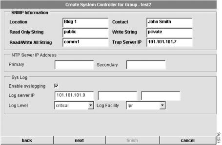
Configure System Controller Network Management
The fourth dialog box that appears allows you to configure network management information for the System Controller. (See .)
Figure 4-20 Create System Controller for Group Dialog Box (4 of 8)
To configure network management information:
1
Enter the location of the System Controller.
The physical location of this System Controller (for example, Bldg. 6).
2
Enter a contact.
The contact person for this System Controller system.
3
Enter a read-only string.
The Simple Network Management Protocol (SNMP) read community string.
4
Enter a write string.
The SNMP write community string.
5
Enter a read/write all string.
The SNMP read/write all community string.
6
Enter the trap server IP address.
The IP address of trap server host.
7
(Optional.) Configure the primary Network time Protocol (NTP) server and secondary NTP server IP addresses.
The IP address(es) of NTP server(s) synchronize the system clock.
8
(Optional.) Choose to enable or disable syslogging.
When this box is checked, syslogging is enabled, and a log of system activity is created.
9
(Optional.) Configure the log server IP address.
If you enable syslogging, you must specify the IP address of syslog server host.
10
(Optional.) Configure the log level.
You must select a level of logging information. Available levels include:
•
•
•
•
•
•
•
•
11
(Optional.) Select a syslog facility.
The syslog facility to use. Available values include:
•
•
•
•
•
•
•
•
•
•
•
•
•
•
12
Click next.
Proceed to the "Configure System Controller Security" section.
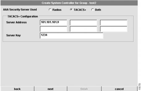
Configure System Controller Security
The fifth dialog box that appears allows you to configure security information for the System Controller. CAM supports two types of authentication, authorization, and accounting (AAA) security servers. The dialog box that displays depends on the type of AAA server you select. (See through .) If you select a Remote Access Dial-In User Service (RADIUS) security server, the following dialog box appears:
Figure 4-21 Create System Controller for Group Dialog Box (5 of 8—RADIUS)
If you select a Terminal Access Controller Access Control System (TACACS+) security server, the following dialog box appears:
Figure 4-22 Create System Controller for Group Dialog Box (5 of 8—TACACS+)
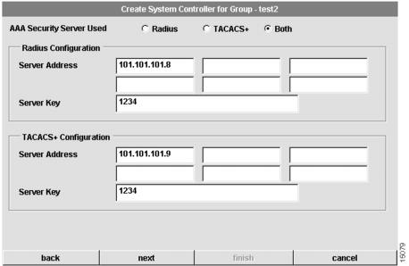
If you select Both, the following dialog box appears:
Figure 4-23 Create System Controller for Group Dialog Box (5 of 8—Both)
To configure security information for the System Controller:
1
Configure the type of AAA security server used.
You can select RADIUS, TACACS+, or both as your remote security database.If you select RADIUS, see . If you select TACACS+, see . If you select Both, see .
2
Configure the security server IP address.
IP address of the remote RADIUS or TACACS+ server host. This host is typically a UNIX system running TACACS+ or RADIUS software.
3
Configure a server key.
Shared secret text string used between the Access Server Shelf and the RADIUS or TACACS+ server. The Access Server Shelf and RADIUS or TACACS+ server use this text string to encrypt passwords and exchange responses.
4
Click next.
If you selected Both, proceed to the Configure System Controller Security Server. If you selected either RADIUS or TACACS+, proceed to the "Configure System Controller Access and Template" section.
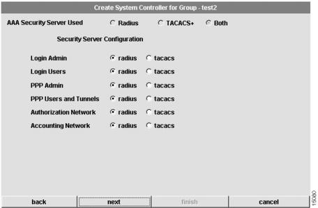
Configure System Controller Security Server
The sixth dialog box that appears only applies if you have selected Both (RADIUS and TACACS+) as the AAA security server used. (See .)
You must configure advanced security features such as authentication method lists, which you then apply to lines and interfaces. These authentication method lists are security profiles that indicate the protocol (AppleTalk Remote Access Protocol [ARAP] or PPP) or login and authentication method (RADIUS, TACACS+, or local authentication).
Figure 4-24 Create System Controller for Group Dialog Box (6 of 8)
To configure security information for the system:
1
Configure advanced server features.
At this dialog you can specify whether RADIUS or TACACS+ provide authentication for the following services:
•
•
•
•
•
•
2
Click next.
Proceed to the "Configure System Controller Access and Template" section.
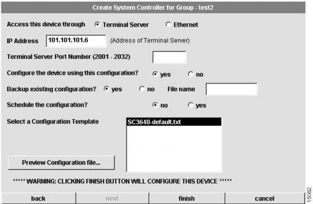
Configure System Controller Access and Template
The seventh dialog box that appears allows you to configure access and template information for the System Controller. (See .)
Figure 4-25 Create System Controller for Group Dialog Box (7 of 8)
To configure security information for the system:
1
Select the access.
The access to the System Controller. You can select a terminal server or Ethernet.
2
Enter an IP address.
The IP address of Ethernet0 or the terminal server.
3
Enter a Terminal Server Port.
The port number for the terminal server. This field only applies if you selected terminal server as the access.
4
Click yes or no to configure the device.
If you click yes, CAM uses this configuration. If you click no, you can use your own configuration tool to download the configuration to the System Controller. However, you cannot use CAM to manage the device, but you need to manually enable the poller to poll the device.
5
The poller is disabled.
This option appears only if you have selected no in Step 4. However, it is always disabled.
6
Click yes or no to backup existing configuration.
If you click yes, CAM will back up the existing configuration on the device. You need to provide a file name (full path) in the file name field. If you click no, the existing configuration is not backed up.
7
Click yes or no to schedule the configuration.
If you click yes, you need to provide schedule information at the Schedule Task dialog box. If you click no, CAM configures after you click finish in Step 10.
8
Select a Configuration Template.
Select from the list of templates. The default template is SC3640-default.txt.
9
Click Preview Configuration File.
You can preview the configuration file created using the selection you made at the previous System Controller dialog boxes. If you need to make changes, click back to the dialog box(es) and make the necessary changes.
10
Click finish.
You have finished everything but the downloading of the configuration.
If you have clicked yes in Step 7, proceed to the "Schedule System Controller Download" section.
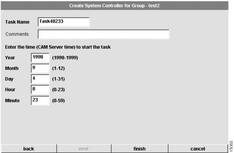
Schedule System Controller Download
When you create or modify a System Controller, you can choose whether to configure the System Controller now or later. If you choose later, you are able to schedule the download at the eighth dialog box that appears. (See .)
Figure 4-26 Create System Controller for Group Dialog Box—(8 of 8)
To schedule System Controller download:
1
Enter a task name.
Enter a task name for the scheduled System Controller configuration procedure. This task can be viewed from the Task Manager in the Tools menu.
2
(Optional.) Enter comments.
Enter any comments in the comments field.
3
Enter the time on the server when the download task should start.
Use these fields to schedule the job. The download will occur when the server time matches the time you configure.
•
•
•
•
•
4
Click finish.
You have scheduled the System Controller download task. You can manage this task through the Task Manager as described in the "Using the Task Manager" section on page 8-59. After a scheduled task executes, you might need to refresh your system. See the "Refreshing Your System" section for details.
Modifying a System Controller
The procedure for modifying a System Controller actually alters the configurations of the shelves in the System Controller instead of simply designing the System Controller through a series of planning sheets. In most cases, by the time you modify a System Controller, you probably have already created shelves and configured them. If the shelves in a System Controller were configured (that is, if CAM downloaded the configurations to the shelves in the System Controller), modifying a System Controller automatically updates all of the shelf configurations. The procedures to modify System Controllers and shelves are similar to those you used to create the System Controllers and shelves.
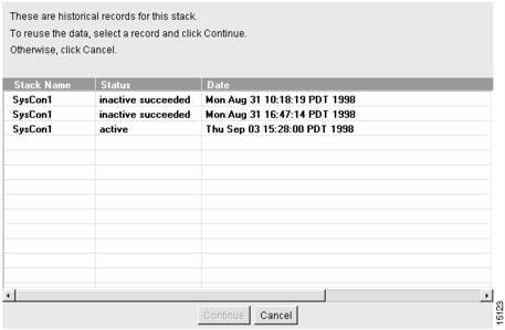
When you modify a System Controller, CAM creates a new configuration record and saves it in the database. CAM lists the contents of that record in the Modify System Controller—Historical Record dialog box. (See .) At the same time, CAM creates a new configuration record for each shelf in the System Controller, saves it to the database, and lists the record in their respective Modify Shelf—Historical Record dialog boxes. The System Controller determines the shelves' status.
By listing all the records that have been created for a System Controller, you can select previous configurations or the most recent configuration record to use for your system.
Figure 4-27 Modify System Controller—Historical Records Dialog Box
The Modify System Controller—Historical Record dialog box lists the following the system record fields:
During the system modification procedure, CAM steps you through a series of dialog boxes in which you can provide new configuration information. Several dialog boxes are common to both the System Controller modification and System Controller creation procedures. At these dialog boxes, you can:
1
2
3
4
5
6
7
8
To modify a System Controller:
1
Select a System Controller from the Device Tree View.
The System Controller you want to modify.
2
Click Configure.
The Task Selection bar displays all the configuration tasks CAM can perform for the System Controller.
3
Click Modify.
A dialog box containing historical records for the selected System Controller appears. (See )
4
Select a stack record.
The stack record you want to modify.
5
Click Continue.
Proceed to "Configure System Controller General Information" section to continue the system modification procedure.
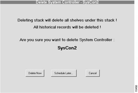
Deleting a System Controller
CautionWhen a System Controller is deleted, all related information about the System Controller and its shelves is deleted from the database. Only use this procedure if you are sure you want to delete the System Controller, its shelves, and its historical data.
To delete a System Controller:
1
Select a System Controller from the Device Tree View.
The System Controller you want to delete.
2
Click Configure.
The Task Selection bar displays all the configuration tasks CAM can perform for the System Controller.
3
Click Delete Now, Schedule later..., or Cancel.
If this is the correct System Controller, and you are sure you want to delete it and all of its historical data, click Delete Now or Schedule Later.... Otherwise, click Cancel. Continue with the "Scheduling System Controller Deletion" section.
Scheduling System Controller Deletion
Scheduling the System Controller deletion is the final step in the delete System Controller procedure. (See .)
Figure 4-28 Delete System Controller Dialog Box
To schedule System Controller deletion:
1
Enter a task name.
Enter a task name for the scheduled System Controller deletion procedure. This task can be viewed from the Task Manager in the Tools menu.
2
(Optional.) Enter comments.
Enter any comments in the comments field.
3
Enter the time on the server when the deletion task should start.
Use these fields to schedule the job. The deletion will occur when the server time matches the time you configure.
•
•
•
•
•
4
Click finish.
You have scheduled the System Controller delete task. You can manage this task through the Task Manager as described in the "Using the Task Manager" section on page 8-59. After a scheduled task executes, you might need to refresh your system. See the "Refreshing Your System" section for details.