Downloads |
 Feedback Feedback
|
Table Of Contents
Shelf Configuration for Stacks
Creating or Modifying a Shelf in a Stack
Configure Shelf Global Information/Passwords
Configure VPDN/Shelf Trunk Interface (Cisco AS5300 Shelves Only)
Configure the Shelf Configuration Parameters
Schedule the Shelf Configuration
Shelf Configuration for System Controllers
Creating or Modifying a Shelf in a System Controller
Creating a Shelf in a System Controller
Modifying a Shelf in a System Controller
Configure Shelf Global Information/Passwords
Configure Trunk Card Information
Configure the Shelf Configuration Parameters
Schedule the Shelf Configuration
Configuring Shelves
This chapter describes the procedures for creating and modifying shelves for two types of containers in Cisco Access Manager (CAM):
•
Shelf Configuration for Stacks
•
Each system is created in CAM by first creating a container (stack or System Controller), and then creating all of the shelves (access servers, routers, and switches) that make up that container. After you have finished creating each shelf, you can have CAM download to that shelf the configuration file based on your choices in the shelf creation process.
Note
You can modify containers and shelves to accommodate changes you make in your system or its network connections using procedures similar to those you used to create the containers and shelves. CAM also allows you to delete these shelves.
Shelf Configuration for Stacks
CAM allows you to configure shelves for stacks in the following ways:
•
Creating or Modifying a Shelf in a Stack
The following sections provide detailed procedures for creating or modifying shelves in a stack.
Note
The steps are:
1
2
3
4
5
You must supply information for all fields presented in bold in each dialog box. (Note that pull-down menus are disabled if your previous stack or shelf configuration choices make them unnecessary.)
CautionWe strongly recommend that you configure the Cisco 3640 (Console Management Shelf) first in a stack.
CautionWe strongly recommend that you delete the running configuration completely before adding a shelf.
CautionWhen you create or modify a shelf and download the configuration to the shelf, the previous configuration file on that shelf is erased and overwritten by the configuration based on the configuration template you select, unless a save of the previous configuration is explicitly specified during the operation.
Creating a Shelf in a Stack
To create a shelf in a stack:
Modifying a Shelf in a Stack
To modify a shelf in a stack:
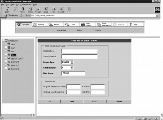
Configure Shelf Global Information/Passwords
Configure the information in the Shelf Configuration dialog box (see ) as the first step in either the Create Shelf or Modify Shelf procedure. (See the following table for a detailed procedure for configuring this information.)
1
(Optional.) Enter a description of the shelf.
This description of the shelf is for your convenience. (64 character limit.)
2
(Optional.) Enter a serial number.
The serial number of the shelf. (32 character limit.)
3
Select a device type.
The device types displayed in this menu depend on two things:
•
–
–
–
•
–
–
–
–
4
Select a shelf number.
The shelf number is a unique identifier of the shelf indicating where it is located in the stack.
This pull-down menu displays only the shelf numbers that are available for the device type you are creating, and depends on the stack type and the shelves that you have already created in the stack.
Note
5
Enter a host name.
A case-sensitive, unique name for the shelf. The default host name contains the stack ID, the device type, and the shelf number. For example, s5AS01 would be the first Access Server Shelf in a stack with the stack ID s5.
6
(Optional.) Enter an original secret password.
When CAM enters the enable mode, if the secret password was preconfigured to the shelf, then it prompts CAM for the original secret password.
Note
7
(Optional.) Enter an original line password.
When CAM Telnets into the shelf, if the line password was preconfigured to the shelf, then it prompts CAM for the original line password.
Note
8
Continue with either the "Configure VPDN/Shelf Trunk Interface (Cisco AS5300 Shelves Only)" section or the "Configure the Shelf Addresses" section, depending on the kind of shelf you are configuring.
•
•
Figure 5-1 Shelf Configuration Dialog Box 1—Shelf Add for Stack
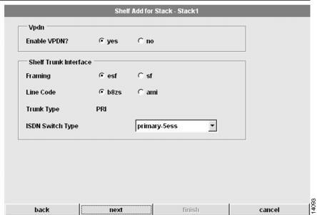
Configure VPDN/Shelf Trunk Interface (Cisco AS5300 Shelves Only)
Configuring VPDN and the Shelf Trunk Interface is the second step in either the Create Shelf or Modify Shelf procedure for Cisco AS5300 shelves only. (See and the following table for instructions.)
1
(Optional.) Enable or disable VPDN support.
(An option for Cisco AS5300-based Cisco AccessPath systems using PRI, T1/PRI, or E1/PRI trunk types, where VPDN was enabled during the Create Stack or Modify Stack process.)
Select yes or no to enable or disable VPDN1 support.
2
Select your framing.
Type of transmission unit used in the T1 or E1 link.
Available choices for Channelized E1 and PRI include:
•
•
Available choices for Channelized T1 and PRI include:
•
•
3
Select a line code.
Variety of Zero Code Suppression used on the link, which in turn affects a number of its characteristics.
Available choices for Channelized E1 and PRI include:
•
•
Available choices for Channelized T1 and PRI include:
•
•
4
(Optional.) Select a trunk type.
Trunk type of the shelf. Valid selections (which are limited depending on the configuration of the stack) include:
•
•
•
Note
5
(PRI trunk type only.) Select an ISDN switch type.
ISDN switch type that services your T1 or E1 PRI lines. You should obtain the correct switch type from your ISDN service provider (telco).
Available choices include:
•
•
•
•
•
•
6
Continue with the next section, "Configure the Shelf Addresses."
Depending on the type of shelf you are configuring, proceed as follows:
•
•
•
1 VPDN = Virtual Private Dialup Network.
Figure 5-2 Shelf Configuration Dialog Box 2—Shelf Add for Stack
Configure the Shelf Addresses
The Shelf Address dialog boxes, which make up the third step in either the Create Shelf or Modify Shelf procedure, vary depending on the shelf you are creating or modifying. Use the appropriate procedure for your shelf.
Note
Configure Cisco 3640 Addresses
To configure the addresses for the Cisco 3640:
1
Configure the Ethernet 1/0 address.
Ethernet port 1/0 IP address.
2
Configure the Ethernet 1/0 mask.
Ethernet port 1/0 subnet mask.
3
Configure the Ethernet 1/1 address.
Ethernet port 1/1 IP address.
4
Configure the Ethernet 1/1 mask.
Ethernet port 1/1 subnet mask.
5
Configure the Loopback1 address.
Network management IP address for the shelf.
6
Configure the Loopback1 mask.
Network management subnet mask for the shelf.
7
Configure the Async Aux IP address.
IP address used for the remote dial-in out-of-band management.
8
Configure the Async Aux IP mask.
Subnet mask for the connection to remote dial-in out-of-band management.
9
Configure the shelf configuration parameters.
Continue with the "Configure the Shelf Configuration Parameters" section.
Configure Cisco AS5300 Addresses
To configure the addresses for the Cisco AS5300:
1
Configure the Ethernet address.
Ethernet IP address.
2
Configure the Ethernet mask.
Subnet mask of the Ethernet.
3
Configure the Loopback0 address.
Virtual IP interface carrying all the dial-in users. Exists only in the Access Server Shelves. Assign an IP network number to the loopback interface, then let each asynchronous interface borrow this network number.
4
Configure the Loopback0 mask.
Subnet mask of Loopback0.
5
Configure the Loopback1 address.
Network management address for the shelf.
6
Configure the Loopback1 mask.
Network management subnet mask for the shelf.
7
Configure the beginning and ending IP local pool addresses.
IP local pool is a pool of IP addresses that exists inside the Access Server Shelves, all of which are on the same IP subnet as loopback interface 0. (In Cisco AccessPath-TS3 systems, the loopback interface 0 is on the first class C network, but the IP pool addresses begin in the second class C network.)
8
Configure the Fast Ethernet address.
The Fast Ethernet IP address.
9
Configure the Fast Ethernet mask.
The subnet mask of the Fast Ethernet.
10
Configure the shelf configuration parameters.
Continue with the "Configure the Shelf Configuration Parameters" section.
Configure Cisco 7206 Addresses
To configure the addresses for the Cisco 7206:
1
Configure the default route.
Static route that can be overridden by dynamic routing information.
2
Configure the FE0/0 primary address.
Fast Ethernet primary IP address.
3
Configure the FE0/0 primary mask.
Fast Ethernet primary subnet mask.
4
Configure the FE1/0 primary address.
Fast Ethernet primary IP address.
5
Configure the FE1/0 primary mask.
Fast Ethernet primary subnet mask.
6
Configure the Loopback1 address.
Network management address for the shelf.
7
Configure the Loopback1 mask.
Network management subnet mask for the shelf.
8
Configure the shelf configuration parameters.
Continue with the "Configure the Shelf Configuration Parameters" section.
Configure Catalyst 5002 Address
To configure the addresses for the Catalyst 5002:
1
Configure an sc0 address.
IP address of the in-band interface.
2
Configure an sc0 mask.
Subnet mask of the in-band interface.
3
Configure the shelf configuration parameters.
Continue with the next section, "Configure the Shelf Configuration Parameters."
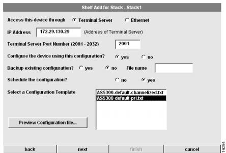
Configure the Shelf Configuration Parameters
Configuring the shelf configuration parameters is the fourth step in either the Create Shelf or Modify Shelf procedure. (See and the following table.)
1
Select an access method.
Select Terminal Server or Ethernet as the method to download the configuration to the shelf.
Note
•
•
2
Enter the IP address for the shelf configuration.
IP address of the Terminal Server or Ethernet port for use when configuring the shelves using a Telnet connection.
On the Cisco 3640, use the IP address of the Ethernet 0 or auxiliary port.
Note
3
(Optional.) Configure the Terminal Server port number.
If you chose Terminal Server to access the shelf, enter the port number.
4
Choose whether or not to configure the device using this configuration.
Select yes to download the configuration to the devices. Select no to generate configuration files and update the CAM database only, without downloading to the devices.
Note
5
(Optional.) Choose whether or not to back up the existing configuration.
Only applies if you selected yes in Step 4. If you choose yes, enter the filename of what you want to call the back up file.
6
(Optional.) Choose whether or not to enable the poller to poll this device.
Only applies if you selected no in Step 4.
7
(Optional.) Choose whether or not to schedule the configuration.
Only applies if you selected yes in Step 4.
Select no if you want the configuration downloaded to the shelf now. Select yes if you want to execute the configuration at a later time.
8
Select a configuration template.
Select a default or custom configuration template.
9
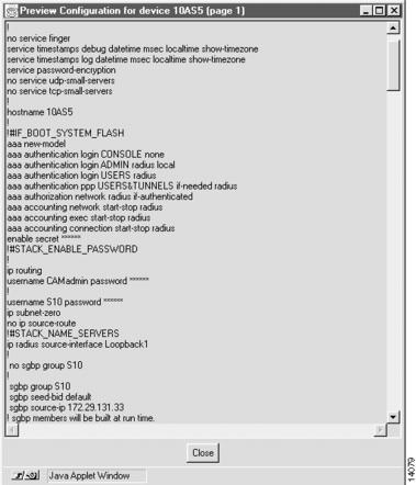
(Optional.) Preview the configuration file.
Click Preview Configuration file... to preview the configuration file that is based on the setting of your input in each dialog box. (See .)
10
Click finish or continue with the next section, "Schedule the Shelf Configuration."
Click finish to start downloading the configuration file. Otherwise, click next to schedule the shelf configuration.
Figure 5-3 Shelf Configuration Dialog Box 4—Shelf Add for Stack
Figure 5-4 View Configuration Popup Screen
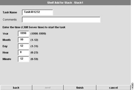
Schedule the Shelf Configuration
Scheduling the shelf configuration is the fifth and final step in either the Create Shelf or Modify Shelf procedure. (See and the following table.)
Figure 5-5 Shelf Configuration Dialog Box 5—Shelf Add for Stack
Tips
If your configuration fails:
1
2
3
4
Deleting a Shelf
Use the following procedure to delete a shelf.
CautionWhen a shelf is deleted, all related information about the shelf is deleted from the database. Only use this procedure if you are sure you want to delete the shelf and its historical data.
1
Select the shelf you want to delete.
Click on the name of the shelf you want to delete.
2
Click Configure.
The Task Selection bar displays all the configuration tasks CAM can perform for shelves.
3
Click Delete.
The first Delete Shelf dialog box appears.
4
Click Delete Now or Schedule Later....
If this is the correct shelf, and you are sure you want to delete it and all of its historical data, click Delete Now or Schedule Later.... Otherwise, click Cancel.
5
(Optional.) Continue with the next section, "Schedule the Shelf Deletion."
Only applies if you chose Schedule Later... in Step 4.
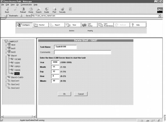
Schedule the Shelf Deletion
Scheduling the shelf deletion is the final step in the Delete procedure. (See and the following table.)
Figure 5-6 Delete Shelf Dialog Box 2—Delete Shelf
Shelf Configuration for System Controllers
CAM allows you to configure shelves for System Controllers in the following ways:
•
Creating or Modifying a Shelf in a System Controller
The following sections provide detailed procedures for creating or modifying shelves in a System Controller.
Note
The steps are:
1
3
4
5
6
You must supply information for all fields presented in bold in each dialog box. (Note that pull-down menus are disabled if your previous System Controller or shelf configuration choices make them unnecessary.)
Note
CautionWhen you create or modify a shelf and download the configuration to the shelf, the previous configuration file on that shelf is erased and overwritten by the configuration based on the configuration template you select, unless a save of the previous configuration is explicitly specified during the operation.
Creating a Shelf in a System Controller
To create a shelf in a System Controller:
Modifying a Shelf in a System Controller
To modify a shelf in a System Controller:
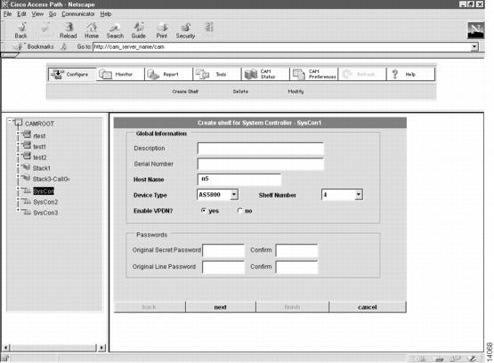
Configure Shelf Global Information/Passwords
Configure the information in the Shelf Configuration dialog box (see ) as the first step in either the Create Shelf or Modify Shelf procedure. (See the following table for a detailed procedure for configuring this information.)
1
(Optional.) Enter a description of the shelf.
This description of the shelf is for your convenience. (64 character limit.)
2
(Optional.) Enter a serial number.
The serial number of the shelf. (32 character limit.)
3
Enter a host name.
A case-sensitive unique name for the shelf.
4
Select a device type.
The available device type includes the Cisco AS5800.
5
Select a shelf number.
The shelf number is a unique identifier of the shelf indicating where it is located in the System Controller. Shelf numbers are even numbers, 0 through 20, going from bottom to top.
This pull-down menu displays only the shelf numbers that are available for the device type you are creating.
6
(Optional.) Enable or disable VPDN support.
(An option for System Controllers using PRI, T1/PRI, or E1/PRI trunk types, where VPDN was enabled during the Create System Controller or Modify System Controller process.)
Select yes or no to enable or disable VPDN1 support.
7
(Optional.) Enter an original secret password.
When CAM enters the enable mode, if the secret password was preconfigured to the shelf, then it prompts CAM for the original secret password.
Note
8
(Optional.) Enter an original line password.
When CAM Telnets into the shelf, if the line password was preconfigured to the shelf, then it prompts CAM for the original line password.
Note
9
Click next.
Continue with the next section, "Configure Trunk/Modem Slots."
1 VPDN = Virtual Private Dialup Network.
Figure 5-7 Shelf Configuration Dialog Box 1—Create Shelf for System Controller
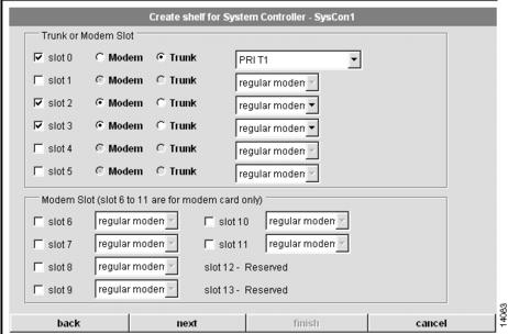
Configure Trunk/Modem Slots
Configuring the Trunk and Modem Slots is the second step in either the Create Shelf or Modify Shelf procedure. (See and the following table.)
1
Select the slots you want to use for the modem feature board(s) and the trunk feature board(s).
Check the boxes next to the slot numbers you want to use.
Note
Note
Note
2
For the slots you selected, choose Modem or Trunk.
Choose Modem or Trunk, depending on whether the slot is for a modem feature board or a trunk feature board.
If you choose Modem, select the modem type:
•
•
If you choose Trunk, select the trunk type:
•
•
•
•
•
•
3
Click next.
Continue with the next section, "Configure Trunk Card Information."
Figure 5-8 Shelf Configuration Dialog Box 2—Create Shelf for System Controller
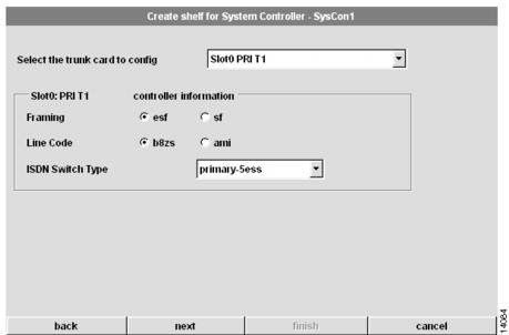
Configure Trunk Card Information
Configuring the Trunk Card Information is the third step in either the Create Shelf or Modify Shelf procedure. (See and the following table.)
1
Select the trunk card to configure.
Select the trunk card to configure based on the slot(s) you configured for the trunk card(s) in the previous section, "Configure Trunk/Modem Slots."
2
Select the framing for the trunk card that you selected.
Type of transmission unit used in the T1 or E1 link.
Available choices for Channelized E1 and PRI include:
•
•
Available choices for Channelized T1 and PRI include:
•
•
3
(Non-CT3 trunk type only.) Select a line code for the trunk card that you selected.
Variety of Zero Code Suppression used on the link, which in turn affects a number of its characteristics.
Available choices for Channelized E1 and PRI include:
•
•
Available choices for Channelized T1 and PRI include:
•
•
4
(PRI trunk type only.) Select an ISDN switch type.
ISDN switch type that services your T1 or E1 PRI lines. You should obtain the correct switch type from your ISDN service provider (telco).
Available choices include:
•
•
•
•
•
•
5
(Non-PRI trunk type only.) Select a signaling type.
The Cisco AS5800 supports channel associated signaling for channelized T1/E1 lines.
Typically, all channels of a channelized T1 or E1 line are used for analog calls. However, the Cisco AS5800 requires a signal converter to perform conversions between R2 signaling and ear and mouth (E&M) signaling.
The Cisco AS5800 supports E&M signaling on its T1/E1 controllers.
Valid selections for Channelized E1 include:
•
•
•
•
Valid selections for Channelized T1 include:
•
•
•
•
•
•
•
6
(E1 R2 configurations only.) Select a CAS1 custom country.
If you selected E1 R2 signaling, you may need to select a country customization for this signaling. The options include:
•
•
•
•
•
•
•
•
•
•
•
•
•
•
•
•
•
•
•
•
7
Click next.
Continue with the next section, "Configure Interface/Addresses."
1 CAS = Channel Associated Signalling.
Figure 5-9 Shelf Configuration Dialog Box 3—Create Shelf for System Controller
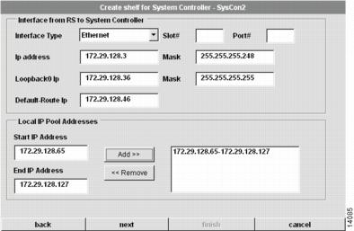
Configure Interface/Addresses
Configuring the interface from the Router Shelf (RS) to the System Controller and configuring the local IP pool addresses is the fourth step in either the Create Shelf or Modify Shelf procedure. (See and the following table for instructions.)
Note
1
Select the interface type.
Select the interface type that connects the shelf to the
System Controller.Available choices include:
•
•
•
2
Enter the slot number.
Slot number for this interface.
3
Enter the port number.
Port number of the slot for this interface.
4
Configure the IP address.
IP address of this interface.
5
Configure the mask.
Subnet mask for this interface.
6
Configure the Loopback0 IP address.
Virtual IP interface carrying all the dial-in users which exists only in the Access Server Shelves. Assign an IP network number to the loopback interface, and then let each asynchronous interface borrow this network number.
7
Configure the Loopback0 mask.
Subnet mask of Loopback0.
8
Configure the Loopback1 IP address.
Network management address for the shelf.
9
Configure the Loopback1 mask.
Network management subnet mask for the shelf.
10
Configure the default route IP address.
IP address of the default route.
11
Configure the starting and ending local IP pool addresses.
Local IP pool is a pool of IP addresses that exists inside the Access Server Shelves, all of which are on the same IP subnet as loopback interface 0.
Specify the discontiguous IP addresses for the dial-in user. Refer to the appropriate Cisco IOS configuration guides and command references documentation for the maximum pool range.
After entering Start IP Address and End IP Address, click the Add>> button to add the address pool to your pool list in the right box. Highlight any pool in the right box and click <<Remove if you want to remove the pool or modify the address(s) from the list. The addresses that you removed display in the Start IP Address and End IP Address fields again. To modify this address pool, change the address(s), and click Add>> again, to add the pool to the list.
12
Click next.
Continue with the next section, "Configure the Shelf Configuration Parameters."
Figure 5-10 Shelf Configuration Dialog Box 4—Create Shelf for System Controller
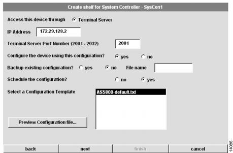
Configure the Shelf Configuration Parameters
Configuring the shelf configuration parameters is the fifth step in either the Create Shelf or Modify Shelf procedure. (See and the following table.)
1
Select an access method.
Select Terminal Server as the method to download the configuration to the shelf.
Note
In the Cisco AS5800, enter the write erase command, and then enter reload.
2
Enter the IP address for the shelf configuration.
IP address of the Terminal Server port for use when configuring the shelves using a Telnet connection.
Note
3
Configure the Terminal Server port number.
Enter the port number for the Terminal Server.
4
Choose whether or not to configure the device using this configuration.
Select yes to download the configuration to the devices. Select no to generate configuration files and update the CAM database only, without downloading to the devices.
Note
5
(Optional.) Choose whether or not to back up the existing configuration.
Only applies if you selected yes in Step 4. If you choose yes, enter the filename of what you want to call the back up file.
6
(Optional.) Choose whether or not to enable the poller to poll this device.
Only applies if you selected no in Step 4.
7
(Optional.) Choose whether or not to schedule the configuration.
Only applies if you selected yes in Step 4.
Select no if you want the configuration downloaded to the shelf now. Select yes if you want to execute the configuration at a later time.
8
Select a configuration template.
Select a default or custom configuration template.
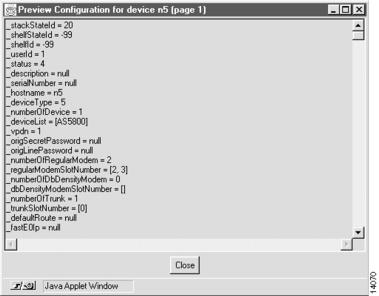
9
(Optional.) Preview the configuration file.
Click Preview Configuration file... to preview the configuration file that is based on the setting of your input in each dialog box. (See .)
10
Click finish or continue with the next section, "Schedule the Shelf Configuration."
Click finish to start downloading the configuration file. Otherwise, click next to schedule the shelf configuration.
Figure 5-11 Shelf Configuration Dialog Box 5—Create Shelf for System Controller
Figure 5-12 View Configuration Popup Screen
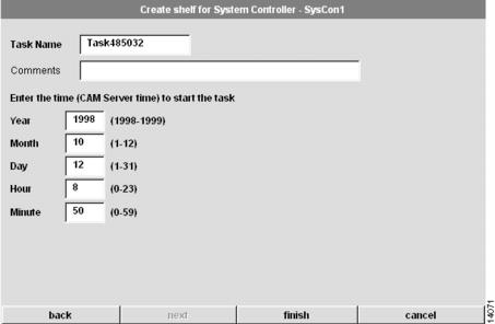
Schedule the Shelf Configuration
Scheduling the shelf configuration is the sixth and final step in either the Create Shelf or Modify Shelf procedure. (See and the following table.)
Figure 5-13 Shelf Configuration Dialog Box 6—Create Shelf for System Controller
Tips
If your configuration fails:
1
2
3
4
Deleting a Shelf
Use the following procedure to delete a shelf.
CautionWhen a shelf is deleted, all related information about the shelf is deleted from the database. Only use this procedure if you are sure you want to delete the shelf and its historical data.
1
Select the shelf you want to delete.
Click on the name of the shelf you want to delete.
2
Click Configure.
The Task Selection bar displays all the configuration tasks CAM can perform for shelves.
3
Click Delete.
The first Delete Shelf dialog box appears.
4
Click Delete Now or Schedule Later....
If this is the correct shelf, and you are sure you want to delete it and all of its historical data, click Delete Now or Schedule Later.... Otherwise, click Cancel.
5
(Optional.) Continue with the next section, "Schedule the Shelf Deletion."
Only applies if you chose Schedule Later... in Step 4.
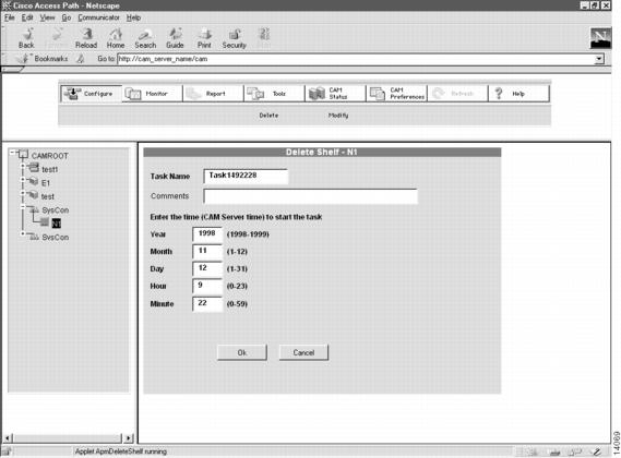
Schedule the Shelf Deletion
Scheduling the shelf deletion is the final step in the Delete procedure. (See and the following table.)
Figure 5-14 Delete Shelf Dialog Box 2—Delete Shelf