Setting Up OER Network Components
Available Languages
Table Of Contents
Setting Up OER Network Components
Prerequisites for Setting Up OER Network Components
Restrictions for Setting Up OER Network Components
Information About Setting Up OER Network Components
Border Routers in an OER-Managed Network
OER Border Router Support for Cisco Catalyst 6500 Series Switches
OER-Managed Network Interfaces
How to Set Up OER Network Components
Setting Up the OER Master Controller
Key Chain Authentication for OER
Master Controller Process Disablement
Setting Up an OER Border Router
Interface Configuration in an OER-Managed Network
Disabling a Border Router Process
Configuring an Interim Border Router
Configuring OER to Control Traffic with Static Routing in Networks Using NAT
Inside Global Addresses Overloading
Configuring iBGP Peering on the Border Routers Managed by OER
Redistributing BGP Routes into an IGP in an OER-Managed Network
Redistributing Static Routes into an IGP in an OER-Managed Network
Redistributing Static Routes into EIGRP in an OER-Managed Network
Registering an Application Interface Provider and Configuring Host Devices
Displaying Information about Application Interface Provider Activity
Configuration Examples for Setting Up OER Network Components
Configuring the OER Master Controller: Example
Configuring an OER Border Router: Example
Configuring an Interim Border Router: Example
Configuring OER to Control Traffic with Static Routing in Networks Using NAT: Example
Configuring iBGP Peering on the Border Routers Managed by OER: Example
Redistributing BGP Routes into an IGP in an OER-Managed Network: Example
Redistributing Static Routes into an IGP in an OER-Managed Network: Example
Redistributing Static Routes into EIGRP in an OER-Managed Network: Example
OER Master Controller and Two Border Routers Deployment: Example
OER Master Controller and Border Router Deployed on a Single Router: Example
Registering an Application Interface Provider and Configuring Host Devices: Example
Feature Information for Setting Up OER Network Components
Setting Up OER Network Components
First Published: January 29, 2007Last Updated: August 21, 2007This module describes the concepts and tasks to help you set up the network components required for an Optimized Edge Routing (OER)-managed network. OER network components are described and configuration tasks are provided to help you configure a master controller (MC) and one or more border routers (BRs) that enable communication between these two software components.
Finding Feature Information in This Module
Your Cisco IOS software release may not support all of the features documented in this module. To reach links to specific feature documentation in this module and to see a list of the releases in which each feature is supported, use the "Feature Information for Setting Up OER Network Components" section.
Finding Support Information for Platforms and Cisco IOS and Catalyst OS Software Images
Use Cisco Feature Navigator to find information about platform support and Cisco IOS and Catalyst OS software image support. To access Cisco Feature Navigator, go to http://www.cisco.com/go/cfn. An account on Cisco.com is not required.
Contents
•
Prerequisites for Setting Up OER Network Components
•
•
•
•
•
Prerequisites for Setting Up OER Network Components
•
•
•
If you have configured internal Border Gateway Protocol (iBGP) on the border routers, BGP peering must be either established and consistently applied throughout your network or redistributed into the Interior Gateway Protocol (IGP).
If an IGP is deployed in your network, static route redistribution must be configured with the redistribute command. IGP or static routing should also be applied consistently throughout an OER-managed network; the border router should have a consistent view of the network.
Restrictions for Setting Up OER Network Components
•
•
•
•
•
Information About Setting Up OER Network Components
To configure a basic OER-managed network, you should understand the following concepts:
•
•
OER-Managed Network
Figure 1 shows an OER-managed network. This network contains a master controller and two border routers. OER is configured on Cisco routers using the Cisco IOS command-line interface (CLI). OER deployment has two primary components: a master controller and one or more border routers. The master controller is the intelligent decision maker, while the border routers are enterprise edge routers with exit interfaces at the network edge. Border routers are either used to access the Internet or used as WAN exit links. OER communication between the master controller and the border routers is carried separately from routing protocol traffic. This communication is protected by Message Digest 5 (MD5) authentication. Each border router has both an external interface, which is connected, for example, to an ISP by a WAN link, and an internal interface that is reachable by the master controller.
Figure 1 OER-Managed Network
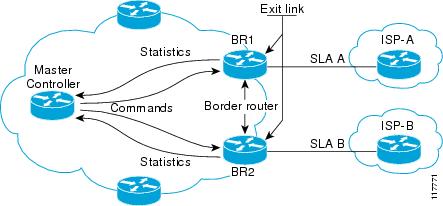
External interfaces are used to forward outbound traffic from the network and as the source for active monitoring. Internal interfaces are used for OER communication and for passive monitoring. In Cisco IOS Release 12.4(9)T, the ability to monitor and control inbound traffic was introduced. At least one external and one internal interface must be configured on each border router. At least two external interfaces are required in an OER-managed network. A local interface is configured on the border router for communication with the master controller.
OER Master Controller
The master controller is a single router that coordinates all OER functions within an OER-managed network. A Cisco router can be configured either to run a standalone master controller process or to perform other functions, such as routing or running a border router process. Figure 2 shows an example of a standalone router configured as a master controller.
Figure 2 Master Controller Example
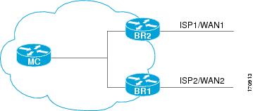
The master controller maintains communication and authenticates the sessions with the border routers. Outbound traffic flows are monitored by the border routers using active or passive monitoring, and the data is collected in a central policy database residing on the router configured as the master controller. Then the master controller applies default or user-defined policies to alter routing to optimize prefixes and exit links. OER administration and control is centralized on the master controller, which makes all policy decisions and controls the border routers. The master controller does not have to be in the traffic forwarding path, but it must be reachable by the border routers. The master controller can support up to 10 border routers and up to 20 OER-managed external interfaces.
Central Policy Database
The master controller continuously monitors the network and maintains a central policy database in which collected statistical information is stored. The master controller compares long-term and short-term measurements. The long-term measurements are collected every 60 minutes. Short-term measurements are collected every 5 minutes. The master controller analyzes these statistics to determine which routes have the lowest delay, highest outbound throughput, relative or absolute packet loss, relative or absolute link cost, and prefix reachability to analyze and optimize the performance of monitored prefixes and to distribute the load from overutilized exit links to underutilized exit links. The locations of the exit links on the border routers are shown in Figure 1.

Tip
Border Routers in an OER-Managed Network
The border router is an enterprise edge router with one or more exit links to another participating network, such as an Internet Service Provider (ISP), and is the site where all policy decisions and changes to routing in the network are enforced. The border router participates in prefix monitoring and route optimization by first reporting prefix and exit link measurements to the master controller and then by enforcing policy changes received from the master controller. The border router enforces policy changes by injecting a preferred route to alter routing in the network. The border router is deployed on the edge of the network, so the border router must be in the forwarding path. A border router process can be enabled on the same router as a master controller process.
Policy Enforcement Point
The border router is the policy enforcement point. Default or user-defined policies are configured on the master controller to set the performance level for prefixes and exit links. The master controller automatically alters routing in the OER-managed network, as necessary, by sending control commands to the border routers to inject a preferred route. The preferred route is advertised or redistributed through the internal network. The preferred route alters default routing behavior so that out-of-policy prefixes are moved from overutilized exit links to underutilized exit links, bringing prefixes and exit links in-policy, thus optimizing the overall performance of the enterprise network.
Tip
Single Hop Peer Restriction Avoidance using OER Interim Border Routers
In Cisco IOS Release 12.4(2)T and 12.2(33)SRB, support for a border router that is more than one hop away from another border router was introduced. In releases prior to Cisco IOS Release 12.4(2)T, the border routers must be one hop away from each other. However, if the design of your network requires the border routers to be separated by more than one hop, a Cisco router between the border routers can be configured as an interim border router. The interim border routers act as transit routers between the border routers in your network. The master controller discovers the paths between interim and standard border routers and policy routes traffic through the appropriate external interface on a standard border router.
The configuration of an interim border router is similar to standard border router configuration. There is only one exception. No external interfaces are defined in the master controller configuration for the interim border router. However, a single internal interface must be configured for the interim border router to establish connectivity with the master controller. The configuration on the interim border router is the same as with a standard border router.

Note
OER Border Router Support for Cisco Catalyst 6500 Series Switches
In Cisco IOS Release 12.2(33)SXH support for using a Cisco Catalyst 6500 series switch as an OER border router was introduced. Only border router functionality is included in the Cisco IOS Release 12.2(33)SXH images; no master controller configuration is available. The master controller that communicates with the Cisco Catalyst 6500 series switch being used as a border router must be a router running Cisco IOS Release 12.4(6)T or a later release.
The OER master controller software has been modified to handle the limited functionality supported by the Cisco Catalyst 6500 border routers. Using the Route Processor (RP), the Catalyst 6500 border routers can capture throughput statistics only for a traffic class compared to the delay, loss, unreachability, and throughput statistics collected by non-Catalyst 6500 border routers. A master controller will automatically detect the limited capabilities of the Catalyst 6500 border routers and will downgrade other border routers to capture only the throughput statistics for traffic classes. By ignoring other types of statistics, the master controller is presented with a uniform view of the border router functionality.
If one of the border router is identified as a Catalyst 6500 border router, then the master controller starts periodic active probing of the all the traffic classes under OER control and ignores the passive performance statistics. Active probing results received for each traffic class are evaluated against the policies configured for that traffic class.
For more details about profiling and monitoring modifications introduced to support the Cisco Catalyst 6500 series switch as an OER border router, see the "Measuring the Traffic Class Performance and Link Utilization Using OER" module and the "Using OER to Profile the Traffic Classes" module.
OER-Managed Network Interfaces
An OER-managed network must have at least two egress interfaces that can carry outbound traffic and that can be configured as external interfaces. These interfaces should connect to an ISP or WAN link (Frame-Relay, ATM) at the network edge. The router must also have one interface (reachable by the internal network) that can be configured as an internal interface for passive monitoring. There are three interface configurations required to deploy OER:
•
•
•
Tip
The following interface types can be configured as external and internal interfaces:
•
•
•
•
•
•
•
•
•
•
•
•
•
The following interface types can be configured as local interfaces:
•
•
•
•
•
•
•
•
•
•
•
•
•
•
•
•
•
Note
OER Deployment Scenarios
OER can be deployed in an enterprise network, remote office network, or small office home office (SOHO) network using one of the following three configurations shown in Figure 3:
•
•
•
Figure 3 OER Deployment Scenarios
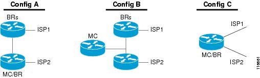
In each deployment scenario, a single master controller is deployed. The master controller does not have to be in the traffic forwarding path but must be reachable by the border routers. A master controller process can be enabled on router that is also configured to run a border router process. The master controller can support up to 10 border routers and up to 20 OER-managed external interfaces. At least one border router process and two external interfaces are required in an OER-managed network.
Note
Routing Control Using OER
Figure 4 shows an OER-managed network. The master controller alters IPv4 routing behavior inside of the OER-managed network to optimize traffic class and exit link performance. OER uses a command and response protocol to manage all communication between the border router and the master controller. The border routers are enterprise edge routers. Routing protocol peering or static routing is established between the border routers and internal peers. The border routers advertise a default route to internal peers through BGP peering, static routing, or route redistribution into an IGP. The master controller alters routing behavior in the OER-managed network by sending control commands to the border routers to inject a preferred route into the internal network.
Figure 4 OER Controls Default Routing Behavior Through Peering or Redistribution
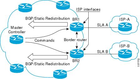
When the master controller determines the best exit for a traffic class prefix, it sends a route control command to the border router with the best exit. The border router searches for a parent route for the monitored prefix. The BGP routing table is searched before the static routing table. The parent route can be a default route for the monitored prefix. If a parent route is found that includes the prefix (the parent route prefix may be equivalent or less specific than the original prefix) and points to the desired exit link by either the route to its next hop or by a direct reference to the interface, a preferred route is injected into the internal network from the border router. OER injects the preferred route where the first parent is found. The preferred route can be an injected BGP route or an injected static route. The preferred route is learned by internal peers, which in turn recalculate their routing tables, causing the monitored prefix to be moved to the preferred exit link. The preferred route is advertised only to the internal network, not to external peers.
Border Router Peering with the Internal Network
The master controller alters default routing behavior in the OER-managed network by injecting preferred routes into the routing tables of the border routers. The border routers peer with other routers in the internal network through BGP peering, BGP or static route redistribution into an IGP, or static routing. The border routers advertise the preferred route to internal peers.
The border routers should be close to one another in terms of hops and throughput and should have a consistent view of the network; routing should be configured consistently across all border routers. The master controller verifies that a monitored prefix has a parent route with a valid next hop before it commands the border routers to alter routing. The border router will not inject a route where one does not already exist. This behavior is designed to prevent traffic from being lost because of an invalid next hop.
Note
BGP Peering with OER
Standard iBGP peering can be established between the border routers and other internal peers. External BGP (eBGP) peering or a default route is configured to the ISP. In an iBGP network, the local preference attribute is used to set the preference for injected routes. Local preference is a discretionary attribute that is used to apply the degree of preference to a route during BGP best-path selection. This attribute is exchanged only between iBGP peers and is not advertised outside of the OER-managed network or to eBGP peers. The prefix with the highest local preference value is locally advertised as the preferred path to the destination. OER applies a local preference value of 5000 to injected routes by default. A local preference value from 1 to 65535 can be configured.
Note
Note
BGP Redistribution into an IGP
BGP redistribution can be used if the border routers are configured to run BGP (for ISP peering for example) and the internal peers are configured to run another routing protocol (such as Enhanced Interior Gateway Routing Protocol [EIGRP], Open Shortest Path First [OSPF] or Routing Information Protocol [RIP]). The border routers can advertise a single, default route or full routing tables to the internal network. If you use BGP to redistribute more than a default route into an IGP, we recommend that you use IP prefix-list and route-map statements to limit the number of redistributed prefixes (BGP routing tables can be very large).
Static Routing and Static Route Redistribution into an IGP
Static routing or static route redistribution can be configured in the internal network. OER alters routing for this type of network by injecting temporary static routes. The temporary static route replaces the parent static route. OER will not inject a temporary static route where a parent static route does not exist. OER applies a default tag value of 5000 to identify the injected static route. In a network where only static routing is configured, no redistribution configuration is required. In a network where an IGP is deployed and BGP is not run on the border routers, static routes to border router exit interfaces must be configured, and these static routes must be redistributed into the IGP.

Caution
Split Prefixes Injected into the Routing Table
When configured to control a subset of a larger network, the master controller will add an appropriate route or split prefix to the existing routing table, as necessary. A split prefix is a more specific route that is derived from a less specific parent prefix. For example, if a /24 prefix is configured to be optimized, but only a /16 route is installed to the routing table, the master controller will inject a /24 prefix using the attributes of the /16 prefix. Any subset of the less-specific prefix can be derived, including a single host route. Split prefixes are processed only inside the OER-managed network and are not advertised to external networks. If BGP is deployed in the OER-managed network, the master controller will inject a more specific BGP route. If BGP is not deployed, the master controller will inject a more specific temporary static route.
OER and NAT
When Cisco IOS OER and NAT functionality are configured on the same router and OER controls the routing for a traffic class using static routing, some applications may fail to operate due to dropped packets. This dropping of packets behavior is seen when static routing is used to connect to multiple ISPs from the same router, OER uses static routing to control the traffic class routing, and one or more of the ISPs use Unicast Reverse Path Forwarding (Unicast RPF) filtering for security reasons. Packets are dropped at the ingress router performing Unicast RPF because OER changes the route for an outgoing packet for a traffic class from one exit interface to another after the NAT translation from a private IP address to a public IP address is performed. When the packet is transmitted, Unicast RPF filtering at the ingress router (for example, an ISP router) will show a different source IP address from the source IP address pool assigned by NAT, and the packet is dropped. For example, Figure 5 shows how OER works with NAT.
Figure 5 OER with NAT
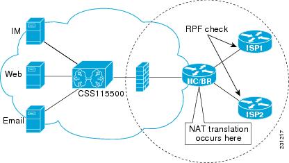
The NAT translation occurs at the router that is connected to the internal network, and this router can be a border router or a combined master controller and border router. If OER changes routes to optimize traffic class performance and to perform load balancing, traffic from the border router in Figure 5 that was routed through the interface to ISP1 may be rerouted through the interface to ISP2 after the traffic performance is measured and policy thresholds are applied. The RPF check occurs at the ISP routers and any packets that are now routed through ISP2 will fail the RPF check at the ingress router for ISP2 because the IP address of the source interface has changed.
The solution involves a minimal configuration change with a new keyword, oer, that has been added to the ip nat inside source command. When the oer keyword is configured, new NAT translations are given the source IP address of the interface that OER has selected for the packet and OER forces existing flows to be routed through the interface for which the NAT translation was created. For example, OER is configured to manage traffic on a border router with two interfaces, InterfaceA to ISP1 and InterfaceB to ISP2 in Figure 5. OER is first configured to control a traffic class representing Web traffic and the NAT translation for this traffic already exists with the source IP address in the packets set to InterfaceA. OER measures the traffic performance and determines that InterfaceB is currently the best exit for traffic flows, but OER does not change the existing flow. When OER is then configured to learn and measure a traffic class representing e-mail traffic, and the e-mail traffic starts, the NAT translation is done for InterfaceB. The OER static routing NAT solution is a single box solution and configurations with interfaces on multiple routers using NAT and managed by OER are not supported. Network configurations using NAT and devices such as PIX firewalls that do not run Cisco IOS software are not supported.
For details about configuring the OER static routing NAT solution, see the "Configuring OER to Control Traffic with Static Routing in Networks Using NAT" task.
OER Application Interface
In Cisco IOS Release 12.4(15)T support for an OER application interface was introduced. The OER application interface defines the mode of communication and messaging between applications and the network for the purpose of optimizing the traffic associated with the applications. A provider is defined as an entity outside the network in which the router configured as an OER master controller exists, for example, an ISP, or a branch office of the same company. The provider has one or more host devices running one or more applications that use the OER application interface to communicate with an OER master controller. A provider must be registered with an OER master controller before an application on a host device can interface with OER. Host devices in the provider network running an application that communicates with OER must also be configured at an OER master controller with an IP address and key chain password.
After registration, a host device in the provider network can initiate a session with an OER master controller. When a provider application initiates a session with an OER master controller, a session identifier (ID) number is allocated to the session. After a session is established, the application can send a request for reports containing performance numbers for traffic classes, dynamically create policies to influence the existing traffic classes, or specify new traffic class criteria.
The application interface can be used by Cisco partners to develop applications. An example of application developed by a partner is OER Manager by Fluke Networks. OER Manager is a complete graphical-user interface (GUI) interface for the Optimized Edge Routing technology. It provides detailed reporting on traffic class performance and OER behavior as well as easy-to-use configuration of OER traffic classes and policies. For more details about OER Manager, go to http://www.flukenetworks.com/pfr.
The OER application interface permits a maximum of five concurrent sessions, and keepalives are used to check that the session between the host application device and the OER master controller is still active. If the session is dropped, all policies created in the session are dropped. An application may negotiate an ability for the session to persist in the case of a temporary outage.
Application Interface Priority
The OER application interface has three main levels of priority to help resolve conflicts with requests coming from providers, host devices, and policies. In Table 1 the three priority levels are shown with the scope of the priority, whether the priority level can be configured on the master controller, the range and default values, if applicable.
When multiple providers are registered with OER, an optional priority value can be specified to give OER the ability to order requests coming in from multiple providers. Host devices in a provider network can also be assigned a priority. The lower the priority value, the higher the priority. If you configure a priority, each provider must be assigned a different priority number. If you try to assign the same priority number to two different providers, an error message is displayed on the console. Host devices must also be configured with different priority numbers if a priority is configured. If a priority has not been configured for the provider or host device, the priority is set to the default value of 65535, which is the lowest priority.
The application administrator assigns a priority to all applications. This priority is conveyed to the Network in terms of a policy priority. The lower the application priority number, the higher the priority of the application. Policy priority is handled using the policy sequence number. A policy sequence number—see Table 2—is a 64 bit number calculated by placing provider priority in bytes 1 and 2, host priority in bytes 3 and 4, policy priority in bytes 5 and 6 and Session ID in bytes 7 and 8. The policy sequence number is calculated by the OER master controller. An example policy sequence number is 18446744069421203465, representing a provider priority value of 65535, a host priority of 65535, a policy priority of 101, and a session ID of 9.
Use the show oer master policy command to view the policy sequence number. The lower the sequence number, the higher the priority for the policy.
Table 2 Formulation of a Policy Sequence Number
Provider Priority
Host Priority
Policy Priority
Session ID
In the situation where an application tries to create two policies with same policy priority; the second policy creation attempt will fail.
OER Application Interface Reporting Deployment
An application communicating through an OER application interface can request performance reports from OER and use the report information to create graphs and charts of the information. Figure 6 shows a diagram of an example reporting model. In this example, the topology contains multiple sites using OER within the site. Each site has a master controller but the company wants to review reports about activities in each site such as overall inter-site traffic activity, voice and video traffic activity, and data center access reports. An OER application interface solution is implemented with a reporting application—see Figure 6—that resides in a central location. The reporting application is registered at each OER master controller and the application initiates a session with each master controller and requests traffic class performance information. The master controller at each site exports information to the application, which consolidates the information and displays graphs and charts. Reports can be requested at specified intervals to keep the information on the reporting application updated.
Figure 6 OER Application Interface Reporting Model
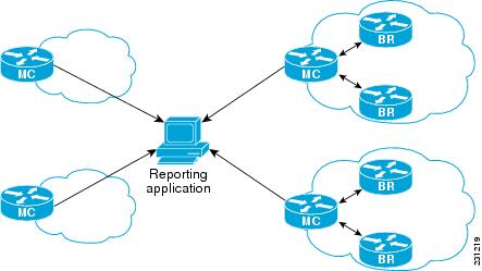
At each site the master controller can monitor provider activity. Several Cisco IOS command-line interface (CLI) commands allow you to view provider information including details about dynamic policies created by the application. Reporting can also be implemented for a single site.
In summary, the OER application interface provides an automated method for networks to be aware of applications and provides application-aware performance routing.
OER Logging and Reporting
Cisco IOS OER supports standard syslog functions. The notice level of syslog is enabled by default. System logging is enabled and configured in Cisco IOS software under global configuration mode. The logging command in OER master controller or OER border router configuration mode is used only to enable or disable system logging under OER. OER system logging supports the following message types:
•
•
•
•
To modify system, terminal, destination, and other system global logging parameters, use the logging commands in global configuration mode. For more information about global system logging configuration, see to the "Troubleshooting, Logging, and Fault Management" section of the Cisco IOS Network Management Configuration Guide, Release 12.4.
How to Set Up OER Network Components
To set up an OER-managed network you must configure routing protocol peering or redistribution between border routers and peer routers in order for OER to control routing. Perform the first two tasks to set up the OER master controller and OER border routers. After performing these required tasks, the other tasks are optional and depend on the existing routing configuration in your network. For example, if only static routing is configured in your network, no optional configuration tasks are necessary for initial OER configuration.
•
•
•
•
•
•
•
•
•
•
Setting Up the OER Master Controller
Perform this task to set up the OER master controller to manage an OER-managed network. This task must be performed on the router designated as the OER master controller. For an example network configuration of a master router and two border routers, see Figure 7. Communication is first established between the master controller and the border routers with key-chain authentication being configured to protect the communication session between the master controller and the border routers. Internal and external border router interfaces are also specified.
Figure 7 Master Controller and Border Router Diagram
Key Chain Authentication for OER
Communication between the master controller and the border router is protected by key-chain authentication. The authentication key must be configured on both the master controller and the border router before communication can be established. The key-chain configuration is defined in global configuration mode on both the master controller and the border router before key-chain authentication is enabled for master controller-to-border router communication. For more information about key management in Cisco IOS software, see the "Managing Authentication Keys" section of the "Configuring IP Routing Protocol-Independent Features" chapter in the Cisco IOS IP Routing Protocols Configuration Guide, Release 12.4.
Master Controller Process Disablement
To disable a master controller and completely remove the process configuration from the running configuration, use the no oer master command in global configuration mode.
To temporarily disable a master controller, use the shutdown command in OER master controller configuration mode. Entering the shutdown command stops an active master controller process but does not remove any configuration parameters. The shutdown command is displayed in the running configuration file when enabled.
Manual Port Configuration
Communication between the master controller and border router is automatically carried over port 3949 when connectivity is established. Port 3949 is registered with the Internet Assigned Numbers Authority (IANA) for OER communication. Support for port 3949 was introduced in Cisco IOS Release 12.3(11)T and 12.2(33)SRB. Manual port number configuration is required only if you are running Cisco IOS Release 12.3(8)T or if you need to configure OER communication to use a dynamic port number.
Prerequisites
Interfaces must be defined and reachable by the master controller and the border router before an OER-managed network can be configured.
Note
Tip
SUMMARY STEPS
1.
2.
3.
4.
5.
6.
7.
8.
9.
10.
11.
12.
13.
14.
15.
16.
17.
18.
19.
20.
DETAILED STEPS
Step 1
enable
Example:Router> enable
Enables privileged EXEC mode.
•
Step 2
configure terminal
Example:Router# configure terminal
Enters global configuration mode.
Step 3
key chain name-of-chain
Example:Router(config)# key chain border1_OER
Enables key-chain authentication and enters key-chain configuration mode.
•
•
Step 4
key key-id
Example:Router(config-keychain)# key 1
Identifies an authentication key on a key chain.
•
Step 5
key-string text
Example:Router(config-keychain-key)# key-string b1
Specifies the authentication string for the key and enters key-chain key configuration mode.
•
•
•
Step 6
exit
Example:Router(config-keychain-key)# exit
Exits key-chain key configuration mode and returns to key-chain configuration mode.
Step 7
exit
Example:Router(config-keychain)# exit
Exits key-chain configuration mode and returns to global configuration mode.
Step 8
Repeat Step 3 through Step 7 with appropriate changes to configure key chain authentication for each border router.
—
Step 9
oer master
Example:Router(config)# oer master
Enters OER master controller configuration mode to configure a router as a master controller.
•
Note
Step 10
port port-number
Example:Router(config-oer-mc)# port 65534
(Optional) Configures a dynamic port for communication between the master controller and border router.
•
Note
Step 11
logging
Example:Router(config-oer-mc)# logging
Enables syslog messages for a master controller or border router process.
•
Step 12
border ip-address [key-chain key-chain-name]
Example:Router(config-oer-mc)# border 10.1.1.2 key-chain border1_OER
Enters OER-managed border router configuration mode to establish communication with a border router.
•
•
•
Note
Step 13
interface type number external
Example:Router(config-oer-mc-br)# interface Ethernet 1/0 external
Configures a border router interface as an OER-managed external interface.
•
•
TipNote
Step 14
exit
Example:Router(config-oer-mc-br-if)# exit
Exits OER-managed border exit interface configuration mode and returns to OER-managed border router configuration mode.
Step 15
interface type number internal
Example:Router(config-oer-mc-br)# interface Ethernet 0/0 internal
Configures a border router interface as an OER controlled internal interface.
•
•
Note
Step 16
exit
Example:Router(config-oer-mc-br)# exit
Exits OER-managed border router configuration mode and returns to OER master controller configuration mode.
Step 17
Repeat Step 12 through Step 16 with appropriate changes to establish communication with each border router.
—
Step 18
keepalive timer
Example:Router(config-oer-mc)# keepalive 10
(Optional) Configures the length of time that an OER master controller will maintain connectivity with an OER border router after no keepalive packets have been received.
•
Step 19
end
Example:Router(config-oer-mc-learn)# end
Exits OER Top Talker and Top Delay learning configuration mode and returns to privileged EXEC mode.
Step 20
show running-config
Example:Router# show running-config
(Optional) Displays the running configuration to verify the configuration entered in this task.
Examples
The following partial output shows the section of the running configuration file that contains the OER master controller configuration from this task. A second border router was also identified.
Router# show running-config!key chain border1_OERkey 1key-string b1key chain border2_OERkey 1key-string b2oer masterport 65534keepalive 10logging!border 10.1.1.2 key-chain border1_OERinterface Ethernet0/0 internalinterface Ethernet1/0 external!border 10.1.1.3 key-chain border2_OERinterface Ethernet0/0 internalinterface Ethernet1/0 external...Setting Up an OER Border Router
Perform this task to set up an OER border router. This task must be performed at each border router in your OER-managed network. For an example network configuration of a master router and two border routers, see Figure 7. Communication is first established between the border router and the master controller with key-chain authentication being configured to protect the communication session between the border router and the master controller. A local interface is configured as the source for communication with the master controller, and external interfaces are configured as OER-managed exit links.
Interface Configuration in an OER-Managed Network
•
•
•
Tip
Disabling a Border Router Process
To disable a border router and completely remove the process configuration from the running configuration, use the no oer border command in global configuration mode.
To temporarily disable a border router process, use the shutdown command in OER border router configuration mode. Entering the shutdown command stops an active border router process but does not remove any configuration parameters. The shutdown command is displayed in the running configuration file when enabled.
Prerequisites
Perform the task "Setting Up the OER Master Controller" section to set up the master controller and define the interfaces and establish communication with the border routers.
Tip
Restrictions
•
•
•
SUMMARY STEPS
1.
2.
3.
4.
5.
6.
7.
8.
9.
10.
11.
12.
DETAILED STEPS
Step 1
enable
Example:Router> enable
Enables privileged EXEC mode.
•
Step 2
configure terminal
Example:Router# configure terminal
Enters global configuration mode.
Step 3
key chain name-of-chain
Example:Router(config)# key chain border1_OER
Enables key-chain authentication and enters key-chain configuration mode.
•
Step 4
key key-id
Example:Router(config-keychain)# key 1
Identifies an authentication key on a key chain and enters key-chain key configuration mode.
•
Step 5
key-string text
Example:Router(config-keychain-key)# key-string b1
Specifies the authentication string for the key.
•
•
Step 6
exit
Example:Router(config-keychain-key)# exit
Exits key-chain key configuration mode and returns to key-chain configuration mode.
Step 7
exit
Example:Router(config-keychain)# exit
Exits key-chain configuration mode and returns to global configuration mode.
Step 8
oer border
Example:Router(config)# oer border
Enters OER border router configuration mode to configure a router as a border router.
•
Note
Step 9
port port-number
Example:Router(config-oer-br)# port 65534
(Optional) Configures a dynamic port for communication between an OER master controller and border router.
•
Note
Step 10
local type number
Example:Router(config-oer-br)# local Ethernet 0/0
Identifies a local interface on an OER border router as the source for communication with an OER master controller.
•
TipStep 11
master ip-address key-chain key-chain-name
Example:Router(config-oer-br)# master 10.1.1.1 key-chain border1_OER
Enters OER-managed border router configuration mode to establish communication with a master controller.
•
•
Step 12
end
Example:Router(config-oer-br)# end
Exits OER Top Talker and Top Delay learning configuration mode and returns to privileged EXEC mode.
What to Do Next
If the design of your network requires any border routers to be separated by more than one hop, a Cisco router between the border routers can be configured as an interim border router. Support for an interim border router was introduced in Cisco IOS Release 12.4(2)T, 12.2(33)SRB, and later releases. To configure an interim border router. proceed to the "Configuring an Interim Border Router" task.
If your network is configured to use only static routing, no additional configuration is required. The OER-managed network should be operational, as long as valid static routes that point to external interfaces on the border routers are configured. You can proceed to the "Where to Go Next" section at the end of this document for information about further OER customization.
Otherwise, routing protocol peering or static redistribution must be configured between the border routers and other routers in the OER-managed network.
The master controller implements policy changes by altering IP routing behavior in the OER-managed network. If iBGP peering is enabled on the border routers, the master controller will inject iBGP routes into routing tables on the border routers. To configure iBGP peering on the border routers managed by OER, proceed to the "Configuring iBGP Peering on the Border Routers Managed by OER" task.
If BGP is configured on the border routers and another IGP is deployed in the internal network, proceed to the "Redistributing BGP Routes into an IGP in an OER-Managed Network" task for more information about configuring redistribution from BGP into the IGP.
If BGP is not configured in the internal network, then static routes to the border exits must be configured and the static routes must be redistributed into the IGP. For more information, see the "Redistributing Static Routes into an IGP in an OER-Managed Network" task.
If you need to configure static redistribution into EIGRP, see the "Redistributing Static Routes into EIGRP in an OER-Managed Network" task for more information.
Configuring an Interim Border Router
In Cisco IOS Release 12.4(2)T and 12.2(33)SRB, support for a border router that is more than one hop away from another border router was introduced. In releases prior to Cisco IOS Release 12.4(2)T, the border routers must be one hop away from each other. However, if the design of your network requires the border routers to be separated by more than one hop, a Cisco router between the border routers can be configured as an interim border router. The interim border routers act as transit routers between the border routers in your network. The master controller discovers the paths between interim and standard border routers and policy routes traffic through the appropriate external interface on a standard border router.
Perform this task on the master controller to configure an interim border router. The configuration of an interim border router is similar to standard border router configuration. The physical configuration on the interim border router is the same as on a standard border router. The difference is in the configuration on the master controller. Only a single internal interface is configured. No external interface configuration is required.
Prerequisites
•
•
SUMMARY STEPS
1.
2.
3.
4.
5.
6.
7.
8.
9.
10.
11.
DETAILED STEPS
Step 1
enable
Example:Router> enable
Enables privileged EXEC mode.
•
Step 2
configure terminal
Example:Router# configure terminal
Enters global configuration mode.
Step 3
key chain name-of-chain
Example:Router(config)# key chain OER
Enables key-chain authentication and enters key chain configuration mode.
•
Step 4
key key-id
Example:Router(config-keychain)# key 1
Identifies an authentication key on a key chain.
•
Step 5
key-string text
Example:Router(config-keychain-key)# key-string CISCO
Specifies the authentication string for the key.
•
•
Step 6
exit
Example:Router(config-keychain-key)# exit
Exits key chain key configuration mode and enters key chain configuration mode.
Step 7
exit
Example:Router(config-keychain)# exit
Exits key chain configuration mode and returns to global configuration mode.
Step 8
oer master
Example:Router(config)# oer master
Enters OER master controller configuration mode to configure a router as a master controller.
•
Note
Step 9
border ip-address [key-chain key-chain-name]
Example:Router(config-oer-mc)# border 10.100.1.1 key-chain OER
Enters OER-managed border router configuration mode to establish communication with a border router.
•
•
•
Note
Step 10
interface type number internal
Example:Router(config-oer-mc-br)# interface Ethernet 0/1 internal
Configures a border router interface as an OER controlled internal interface.
•
•
Step 11
end
Example:Router(config-oer-mc-br)# end
Exits OER-managed border router configuration mode and returns to privileged EXEC mode.
What to Do Next
If your network is configured to use only static routing without NAT, no additional configuration is required. The OER-managed network should be operational, as long as valid static routes that point to external interfaces on the border routers are configured. You can proceed to the "Where to Go Next" section at the end of this document for information about further OER customization.
If your network is configured to use NAT and static routing is used by OER to control traffic classes, proceed to the "Configuring OER to Control Traffic with Static Routing in Networks Using NAT" task.
Otherwise, routing protocol peering or static redistribution must be configured between the border routers and other routers in the OER-managed network.
The master controller implements policy changes by altering IP routing behavior in the OER-managed network. If iBGP peering is enabled on the border routers, the master controller will inject iBGP routes into routing tables on the border routers. To configure iBGP peering on the border routers managed by OER, proceed to the "Configuring iBGP Peering on the Border Routers Managed by OER" task.
If BGP is configured on the border routers and another IGP is deployed in the internal network, proceed to the "Redistributing BGP Routes into an IGP in an OER-Managed Network" task for more information about configuring redistribution from BGP into the IGP.
If BGP is not configured in the internal network, then static routes to the border exits must be configured and the static routes must be redistributed into the IGP. For more information, see the "Redistributing Static Routes into an IGP in an OER-Managed Network" task.
If you need to configure static redistribution into EIGRP, see the "Redistributing Static Routes into EIGRP in an OER-Managed Network" task for more information.
Configuring OER to Control Traffic with Static Routing in Networks Using NAT
Perform this task to allow OER to control traffic with static routing in a network using NAT. This task allows OER to optimize traffic classes while permitting your internal users access to the internet.
When Cisco IOS OER and NAT functionality are configured on the same router and OER controls the routing for a traffic class using static routing, some applications may fail to operate due to dropped packets. This dropping of packets behavior is seen when static routing is used to connect to multiple ISPs from the same router, OER uses static routing to control the traffic class routing, and one or more of the ISPs use Unicast Reverse Path Forwarding (Unicast RPF) filtering for security reasons.
In this task, the oer keyword is used with the ip nat inside source command. When the oer keyword is configured, new NAT translations are given the source IP address of the interface that OER has selected for the packet and OER forces existing flows to be routed through the interface where the NAT translation was created. This task uses a single IP address but an IP address pool can also be configured. For a configuration example using an IP address pool, see "Configuring OER to Control Traffic with Static Routing in Networks Using NAT: Example" section.
Note
For more details about configuring NAT, see the "Configuring NAT for IP Address Conservation" chapter of the Cisco IOS IP Addressing Services Configuration Guide, Release 12.4T.
NAT
NAT enables private IP internetworks that use nonregistered IP addresses to connect to the Internet. NAT operates on a router, usually connecting two networks together, and translates the private (not globally unique) address in the internal network into legal addresses before packets are forwarded onto another network. NAT can be configured to advertise only one address for the entire network to the outside world. This ability provides additional security, effectively hiding the entire internal network behind that one address.
NAT is also used at the Enterprise edge to allow internal users access to the Internet and to allow Internet access to internal devices such as mail servers.
Inside Global Addresses Overloading
You can conserve addresses in the inside global address pool by allowing the router to use one global address for many local addresses. When this overloading is configured, the router maintains enough information from higher-level protocols (for example, TCP or UDP port numbers) to translate the global address back to the correct local address. When multiple local addresses map to one global address, the TCP or UDP port numbers of each inside host distinguish between the local addresses.
SUMMARY STEPS
1.
2.
3.
4.
5.
6.
7.
8.
9.
10.
11.
12.
13.
14.
15.
16.
DETAILED STEPS
Step 1
enable
Example:Router> enable
Enables privileged EXEC mode.
•
Step 2
configure terminal
Example:Router# configure terminal
Enters global configuration mode.
Step 3
access-list access-list-number {permit | deny} ip-address mask
Example:Router(config)# access-list 1 permit 10.1.0.0 0.0.255.255
Defines a standard access list permitting the IP addresses that are to be translated.
•
Step 4
route-map map-tag [permit | deny] [sequence-number]
Example:Router(config)# route-map isp-1 permit 10
Enters route-map configuration mode to configure a route map.
•
Step 5
match ip address {access-list access-list-name | prefix-list prefix-list-name}
Example:Router(config-route-map)# match ip address access-list 1
Creates an access list or prefix list match clause entry in a route map to identify traffic to be translated by NAT.
•
Step 6
match interface interface-type interface-number [...interface-type interface-number]
Example:Router(config-route-map)# match interface serial 1/0
Creates a match clause in a route map to distribute any routes that match out one of the interfaces specified.
•
Step 7
exit
Example:Router(config-route-map)# exit
Exits route-map configuration mode and returns to global configuration mode.
Step 8
Repeat Step 4 through Step 7 for more route map configurations, as required.
—
Step 9
ip nat inside source {list {access-list-number | access-list-name} | route-map map-name} {interface type number | pool name} [mapping-id map-id | overload | reversible | vrf vrf-name] [oer]
Example:Router(config)# ip nat inside source interface FastEthernet1/0 overload oer
Establishes dynamic source translation with overloading, specifying the interface.
•
•
Step 10
interface type number
Example:Router(config)# interface FastEthernet1/0
Specifies an interface and enters interface configuration mode.
Step 11
ip address ip-address mask
Example:Router(config-if)# ip address 10.114.11.8 255.255.255.0
Sets a primary IP address for the interface.
Step 12
ip nat inside
Example:Router(config-if)# ip nat inside
Marks the interface as connected to the inside.
Step 13
exit
Example:Router(config-if)# exit
Exits interface configuration mode and returns to configuration mode.
Step 14
interface type number
Example:Router(config)# interface ethernet 0
Specifies a different interface and returns to interface configuration mode.
Step 15
ip address ip-address mask
Example:Router(config-if)# ip address 172.17.233.208 255.255.255.0
Sets a primary IP address for the interface.
Step 16
ip nat outside
Example:Router(config-if)# ip nat outside
Marks the interface as connected to the outside.
What to Do Next
Routing protocol peering or static redistribution must be configured between the border routers and other routers in the OER-managed network.
The master controller implements policy changes by altering IP routing behavior in the OER-managed network. If iBGP peering is enabled on the border routers, the master controller will inject iBGP routes into routing tables on the border routers. To configure iBGP peering on the border routers managed by OER, proceed to the "Configuring iBGP Peering on the Border Routers Managed by OER" task.
If BGP is configured on the border routers and another IGP is deployed in the internal network, proceed to the "Redistributing BGP Routes into an IGP in an OER-Managed Network" task for more information about configuring redistribution from BGP into the IGP.
If BGP is not configured in the internal network, then static routes to the border exits must be configured and the static routes must be redistributed into the IGP. For more information, see the "Redistributing Static Routes into an IGP in an OER-Managed Network" task.
If you need to configure static redistribution into EIGRP, see the "Redistributing Static Routes into EIGRP in an OER-Managed Network" task for more information.
Configuring iBGP Peering on the Border Routers Managed by OER
Perform this task at each border router to configure iBGP peering on the border routers managed by OER. The master controller implements policy changes by altering IP routing behavior in the OER-managed network. If iBGP peering is enabled on the border routers, the master controller will inject iBGP routes into routing tables on the border routers. The border routers advertise the preferred route through standard iBGP peering.
The local preference attribute is used to set the preference for injected BGP prefixes. If a local preference value of 5000 or higher has been configured for default BGP routing, you should configure a higher value in OER. Default local preference and static tag values are configurable with the mode command in OER master controller configuration mode.
All OER injected routes remain local to an autonomous system. The no-export community is automatically applied to injected routes to ensure that they are not advertised to external networks. Before injecting a route, the master controller verifies that a parent route with a valid next hop exists. This behavior is designed to prevent traffic from being lost.
Prerequisites
Routing protocol peering must be established in your network and consistently applied to the border routers; the border routers should have a consistent view of the network.
Restrictions
In Cisco IOS Release 12.4(6)T and prior releases, the IP address for each eBGP peering session must be reachable from the border router via a connected route. Peering sessions established through loopback interfaces or with the neighbor ebgp-multihop command are not supported. In Cisco IOS Release 12.4(9)T and 12.2(33)SRB, the neighbor ebgp-multihop command is supported.
SUMMARY STEPS
1.
2.
3.
4.
5.
6.
7.
DETAILED STEPS
What to Do Next
If BGP is configured on the border routers and another IGP is deployed in the internal network, proceed to the "Redistributing BGP Routes into an IGP in an OER-Managed Network" task for more information about configuring redistribution from BGP into the IGP.
If BGP is not configured in the internal network, then static routes to the border exits must be configured and the static routes must be redistributed into the IGP. For more information, see the "Redistributing Static Routes into an IGP in an OER-Managed Network" task.
If you need to configure static redistribution into EIGRP, see the "Redistributing Static Routes into EIGRP in an OER-Managed Network" task for more information.
Redistributing BGP Routes into an IGP in an OER-Managed Network
This task explains how to redistribute BGP routes into an IGP in an OER-managed network. Some of the examples in the "Detailed Steps" section of this task show redistribution into OSPF, but EIGRP, IS-IS, or RIP could also be used in this configuration.
When redistributing BGP routes into any IGP, be sure to use the ip prefix-list and route-map command statements to limit the number of prefixes. Redistributing full BGP routing tables into an IGP can have a detrimental effect on IGP network operation.
Prerequisites
IGP peering, static routing, and static route redistribution must be applied consistently throughout the OER-managed network; the border routers should have a consistent view of the network.
Restrictions
When two or more border routers are deployed in an OER-managed network, the next hop to an external network on each border router, as installed in the RIB, cannot be an IP address from the same subnet.
SUMMARY STEPS
1.
2.
3.
4.
5.
6.
7.
8.
9.
10.
11.
12.
13.
DETAILED STEPS
Step 1
enable
Example:Router> enable
Enables privileged EXEC mode.
•
Step 2
configure terminal
Example:Router# configure terminal
Enters global configuration mode.
Step 3
ip prefix-list list-name [seq seq-value] {deny network/length | permit network/length} [ge ge-value] [le le-value]
Example:Router(config)# ip prefix-list PREFIXES seq 5 permit 10.200.2.0/24
Defines the prefix range to redistribute into the IGP.
•
•
•
Step 4
ip prefix-list list-name [seq seq-value] {deny network/length | permit network/length} [ge ge-value] [le le-value]
Example:Router(config)# ip prefix-list PREFIXES seq 10 deny 0.0.0.0/0
Defines additional prefix list entries.
•
•
•
Step 5
route-map map-tag [permit | deny] [sequence-number]
Example:Router(config)# route-map BGP permit 10
Enters route-map configuration mode to configure a route map.
•
Step 6
match ip address prefix-list prefix-list-name
Example:Router(config-route-map)# match ip address prefix-list PREFIXES
Creates a prefix list match clause entry in a route map to redistribute BGP prefixes.
•
Step 7
exit
Example:Router(config-route-map)# exit
Exits route-map configuration mode and returns to global configuration mode.
Step 8
router bgp autonomous-system-number
Example:Router(config)# router bgp 65534
Enters router configuration mode to configure a BGP routing process.
Step 9
bgp redistribute-internal
Example:Router(config-router)# bgp redistribute-internal
Enables BGP redistribution into an IGP.
Step 10
exit
Example:Router(config-router)# exit
Exits router configuration mode and returns to global configuration mode.
Step 11
router {eigrp autonomous-system-number | is-is [area-tag] | ospf process-id | rip}
Example:Router(config)# router ospf 1
Enters router configuration mode and creates a routing process.
•
Step 12
redistribute static [metric metric-value] [route-map map-tag] [subnets]
Example:Router(config-router)# redistribute static route-map BGP subnets
Redistributes static routes into the specified protocol.
•
•
Note
Step 13
end
Example:Router(config-router)# end
Exits router configuration mode and returns to privileged EXEC mode.
What to Do Next
The master controller implements policy changes by altering default routing behavior in the OER-managed network. If iBGP peering is enabled on the border routers, the master controller will inject iBGP routes into routing tables on the border routers.
If BGP is not configured in the internal network, then static routes to the border exits must be configured and the static routes must be redistributed into the IGP. For more information, see the "Redistributing Static Routes into an IGP in an OER-Managed Network" task.
If you need to configure static redistribution into EIGRP, see the "Redistributing Static Routes into EIGRP in an OER-Managed Network" task for more information.
Redistributing Static Routes into an IGP in an OER-Managed Network
This task shows how to redistribute static routes into an IGP in an OER-managed network. This task should be performed on the border routers.
OER applies a default tag value of 5000 to injected temporary static routes. The static route is filtered through a route map and then redistributed into the IGP. If you use the tag value of 5000 for another routing function, you should use a different tag value for that function, or you can change the default static tag values by configuring the mode command in OER master controller configuration mode.
Before injecting a route, the master controller verifies that a parent route with a valid next hop exists. This behavior is designed to prevent traffic from being lost.
If static routing is configured in your network and no IGP is deployed, OER will inject temporary static routes as necessary. No redistribution or other specific network configuration is required.
The following IGPs are supported; EIGRP, OSPF, Intermediate System-to-Intermediate System (IS-IS), and RIP.
Caution
Note
Prerequisites
IGP peering, static routing, and static route redistribution must be applied consistently throughout the OER-managed network; the border routers should have a consistent view of the network.
Restrictions
When two or more border routers are deployed in an OER-managed network, the next hop to an external network on each border router, as installed in the RIB, cannot be an IP address from the same subnet as the next hop on the other border router.
SUMMARY STEPS
1.
2.
3.
4.
5.
6.
7.
8.
9.
10.
DETAILED STEPS
What to Do Next
If you need to configure static redistribution into EIGRP, see the "Redistributing Static Routes into EIGRP in an OER-Managed Network" task for more information.
Redistributing Static Routes into EIGRP in an OER-Managed Network
This task explains how to redistribute static routes into EIGRP. For EIGRP configurations, a tag is applied to the static route and a distribute list is configured on all egress interfaces.
OER applies a default tag value of 5000 to injected temporary static routes. The static route is filtered through a route map and then redistributed into the IGP.
Before injecting the temporary static route, the master controller verifies that a parent static route with a valid next hop exists. This behavior is designed to prevent traffic from being lost.
Caution
Prerequisites
IGP peering, static routing, and static route redistribution must be applied consistently throughout the OER-managed network; the border routers should have a consistent view of the network.
Restrictions
When two or more border routers are deployed in an OER-managed network, the next hop, as installed in the RIB, to an external network on each border router cannot be an IP address from the same subnet.
SUMMARY STEPS
1.
2.
3.
4.
5.
6.
7.
8.
9.
10.
11.
12.
13.
DETAILED STEPS
Registering an Application Interface Provider and Configuring Host Devices
Perform this task at a master controller to register an application interface provider with the master controller and to configure host devices. In Cisco IOS Release 12.4(15)T the OER application interface was introduced. The OER application interface defines the mode of communication and messaging between applications and the network for the purpose of optimizing the traffic associated with the applications. A provider must be registered with an OER master controller before the application can interface with OER.
Multiple providers can be registered and multiple host devices can be configured under each provider, but a host device cannot be configured under multiple providers. The OER application interface has a maximum number of five concurrent sessions. After the provider is registered using this task, an application running on a host device can initiate a session with the master controller.
To view information about providers and any default policies created by applications using the OER application interface, see the "Displaying Information about Application Interface Provider Activity" section. For more details about the OER application interface, see "OER Application Interface" section.
Prerequisites
The master controller and border routers must be running Cisco IOS Release 12.4(15)T, or later release.
SUMMARY STEPS
1.
2.
3.
4.
5.
6.
7.
DETAILED STEPS
Step 1
enable
Example:Router> enable
Enables privileged EXEC mode.
•
Step 2
configure terminal
Example:Router# configure terminal
Enters global configuration mode.
Step 3
oer master
Example:Router(config)# oer master
Enters OER master controller configuration mode to configure a router as a master controller.
•
Note
Step 4
api provider provider-id [priority value]
Example:Router(config-oer-mc)# api provider 1 priority 3000
Registers a provider with an OER master controller and enters OER master controller application interface provider configuration mode.
•
•
Step 5
host-address ip-address [key-chain key-chain-name] [priority value]
Example:Router(config-oer-mc-api-provider)# host-address 10.1.2.2 key-chain OER_HOST1
Configures information about a host device used by a provider to communicate with an OER master controller.
•
•
Step 6
Repeat Step 5 to configure additional host devices as required.
—
Step 7
end
Example:Router(config-router)# end
Exits OER master controller application interface provider configuration mode and returns to privileged EXEC mode.
Troubleshooting Tips
Use the debug oer api command on the master controller to troubleshoot issues with registering a provider or configuring a host device. Use the detailed keyword with caution in a production network.
Displaying Information about Application Interface Provider Activity
Perform this task on a master controller to display information about providers and any default policies created by applications using the OER application interface. In Cisco IOS Release 12.4(15)T the OER application interface was introduced. The OER application interface defines the mode of communication and messaging between applications and the network for the purpose of optimizing the traffic associated with the applications. This task can be used after a provider is registered with an OER master controller using the Registering an Application Interface Provider and Configuring Host Devices task and an application on a host device initiates a session. The show commands can be entered in any order.
Prerequisites
•
•
SUMMARY STEPS
1.
2.
3.
4.
DETAILED STEPS
Step 1
Enables privileged EXEC mode. Enter your password if prompted.
Router> enableStep 2
This command is used to display provider and host information including the ID of each configured provider, the priority of the provider and the host (if configured), and the IP addresses of each configured host device.
Router# show oer api provider detailAPI Version: Major 2, Minor 0Provider id 1001, priority 65535Host ip 10.3.3.3, priority 65535Session id 9, Version Major 2, Minor 0Num pfx created 2, Num policies created 2Last active connection time (sec) 00:00:01Policy ids : 101, 102,Host ip 10.3.3.4, priority 65535Session id 10, Version Major 2, Minor 0Num pfx created 1, Num policies created 1Last active connection time (sec) 00:00:03Policy ids : 103,Provider id 2001, priority 65535Host ip 172.19.198.57, priority 65535Session id 11, Version Major 2, Minor 0Num pfx created 0, Num policies created 0All Prefix report enabledAll exit report enabledStep 3
This command is used to display policy information. The following example uses the dynamic keyword to display the policies dynamically created by provider applications. Note that the first two dynamic policies were generated by the same host device at 10.3.3.3 and in the same session ID of 9, but the third section is for a different host device at 10.3.3.4.
Router# show oer master policy dynamicDynamic Policies:proxy id 10.3.3.3sequence no. 18446744069421203465, provider id 1001, provider priority 65535host priority 65535, policy priority 101, Session id 9backoff 90 90 90delay relative 50holddown 90periodic 0probe frequency 56mode route controlmode monitor bothmode select-exit goodloss relative 10jitter threshold 20mos threshold 3.60 percent 30unreachable relative 50next-hop not setforwarding interface not setresolve delay priority 11 variance 20resolve utilization priority 12 variance 20proxy id 10.3.3.3sequence no. 18446744069421269001, provider id 1001, provider priority 65535host priority 65535, policy priority 102, Session id 9backoff 90 90 90delay relative 50holddown 90periodic 0probe frequency 56mode route controlmode monitor bothmode select-exit goodloss relative 10jitter threshold 20mos threshold 3.60 percent 30unreachable relative 50next-hop not setforwarding interface not setresolve delay priority 11 variance 20resolve utilization priority 12 variance 20proxy id 10.3.3.4sequence no. 18446744069421334538, provider id 1001, provider priority 65535host priority 65535, policy priority 103, Session id 10backoff 90 90 90delay relative 50holddown 90periodic 0probe frequency 56mode route controlmode monitor bothmode select-exit goodloss relative 10jitter threshold 20mos threshold 3.60 percent 30unreachable relative 50next-hop not setforwarding interface not setresolve delay priority 11 variance 20resolve utilization priority 12 variance 20Step 4
This command is used to display the status of monitored prefixes. Using the report keyword, the following example shows prefix statistics including information about provider report requests for the 10.1.1.0 prefix:.
Router# show oer master prefix 10.1.1.0/24 reportPrefix Performance Report RequestCreated by: Provider 1001, Host 10.3.3.3, Session 9Last report sent 3 minutes ago, context 589855, frequency 4 minPrefix Performance Report RequestCreated by: Provider 1001, Host 10.3.3.4, Session 10Last report sent 1 minutes ago, context 655372, frequency 3 minOER Prefix Statistics:Pas - Passive, Act - Active, S - Short term, L - Long term, Dly - Delay (ms),P - Percentage below threshold, Jit - Jitter (ms),MOS - Mean Opinion ScoreLos - Packet Loss (packets-per-million), Un - Unreachable (flows-per-million),E - Egress, I - Ingress, Bw - Bandwidth (kbps), N - Not applicableU - unknown, * - uncontrolled, + - control more specific, @ - active probe all# - Prefix monitor mode is Special, & - Blackholed Prefix% - Force Next-Hop, ^ - Prefix is deniedPrefix State Time Curr BR CurrI/F ProtocolPasSDly PasLDly PasSUn PasLUn PasSLos PasLLosActSDly ActLDly ActSUn ActLUn EBw IBwActSJit ActPMOS ActSLos ActLLos--------------------------------------------------------------------------------10.1.1.0/24 INPOLICY 0 10.3.3.3 Et4/3 BGPN N N N N N138 145 0 0 N NN N
Configuration Examples for Setting Up OER Network Components
This section contains the following examples:
•
•
•
•
•
•
•
•
•
•
•
Configuring the OER Master Controller: Example
The following configuration example, starting in global configuration mode, shows the minimum configuration required to configure a master controller process to manage the internal network. A key-chain configuration named OER is defined in global configuration mode.
Router(config)# key chain OERRouter(config-keychain)# key 1Router(config-keychain-key)# key-string KEYSTRING2Router(config-keychain-key)# endThe master controller is configured to communicate with the 10.100.1.1 and 10.200.2.2 border routers. The keepalive interval is set to 10 seconds. Route control mode is enabled. Internal and external OER-controlled border router interfaces are defined.
Router(config)# oer masterRouter(config-oer-mc)# keepalive 10Router(config-oer-mc)# loggingRouter(config-oer-mc)# border 10.100.1.1 key-chain OERRouter(config-oer-mc-br)# interface Ethernet 0/0 externalRouter(config-oer-mc-br)# interface Ethernet 0/1 internalRouter(config-oer-mc-br)# exitRouter(config-oer-mc)# border 10.200.2.2 key-chain OERRouter(config-oer-mc-br)# interface Ethernet 0/0 externalRouter(config-oer-mc-br)# interface Ethernet 0/1 internalRouter(config-oer-mc)# exitConfiguring an OER Border Router: Example
The following configuration example, starting in global configuration mode, shows the minimum required configuration to enable a border router. The key-chain configuration is defined in global configuration mode.
Router(config)# key chain OERRouter(config-keychain)# key 1Router(config-keychain-key)# key-string KEYSTRING2Router(config-keychain-key)# endThe key-chain OER is applied to protect communication. An interface is identified to the master controller as the local interface (source) for OER communication.
Router(config)# oer borderRouter(config-oer-br)# local Ethernet 0/1Router(config-oer-br)# master 192.168.1.1 key-chain OERRouter(config-oer-br)# endConfiguring an Interim Border Router: Example
The following configuration example configures an interim border router on a master controller:
Router(config)# key chain OERRouter(config-keychain)# key 1Router(config-keychain-key)# key-string keystring3Router(config-keychain-key)# exitRouter(config-keychain)# exitRouter(config)# oer masterRouter(config-oer-mc)# border 10.100.1.1 key-chain OERRouter(config-oer-mc-br)# interface Ethernet 0/1 internalRouter(config-oer-mc-br)# endConfiguring OER to Control Traffic with Static Routing in Networks Using NAT: Example
The following configuration example configures a master controller to allow OER to control traffic with static routing in a network using NAT. This example shows how to use a pool of IP addresses for the NAT translation.
Figure 8 OER and NAT Network Diagram
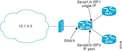
In Figure 8 there is a combined master controller and border router that is connected to the Internet through two different ISPs. The configuration below allows OER to optimize traffic classes while permitting the internal users access to the internet. In this example the traffic classes to be translated using NAT are specified using an access list and a route map. The use of a pool of IP addresses for NAT translation is then configured and the oer keyword is added to the ip nat inside source command to configure OER to keep existing traffic classes flowing through the interface that is the source address that was translated by NAT. New NAT translations can be given the IP address of the interface that OER has selected for the packet.
Note
Router(config)# access-list 1 permit 10.1.0.0 0.0.255.255Router(config)# route-map isp-2 permit 10BGP permit 10Router(config-route-map)# match ip address access-list 1Router(config-route-map)# match interface serial 2/0Router(config-route-map)# exitRouter(config)# ip nat pool ISP2 209.165.201.1 209.165.201.30 prefix-length 27Router(config)# ip nat inside source route-map isp-2 pool ISP2 oerRouter(config)# interface FastEthernet 3/0Router(config-if)# ip address 10.1.11.8 255.255.255.0Router(config-if)# ip nat insideRouter(config-if)# exitRouter(config)# interface serial 1/0Router(config-if)# ip address 192.168.3.1 255.255.255.0Router(config-if)# ip nat outsideRouter(config-if)# exitRouter(config)# interface serial 2/0Router(config-if)# ip address 172.17.233.208 255.255.255.0Router(config-if)# ip nat outsideRouter(config-if)# endFor more details about configuring NAT, see the "Configuring NAT for IP Address Conservation" chapter of the Cisco IOS IP Addressing Services Configuration Guide, Release 12.4T.
Configuring iBGP Peering on the Border Routers Managed by OER: Example
The following example, starting in global configuration mode, shows how to establish peering between two routers in autonomous system 65534 and to configure standard community exchange:
Border Router Configuration
Router(config)# router bgp 65534Router(config-router)# neighbor 10.100.1.3 remote-as 65534Router(config-router)# address-family ipv4Router(config-router-af)# neighbor 10.100.1.3 activateRouter(config-router-af)# neighbor 10.100.1.3 send-community standardInternal Border Peer Configuration
Router(config)# router bgp 65534Router(config-router)# neighbor 10.100.1.2 remote-as 65534Router(config-router)# address-family ipv4Router(config-router-af)# neighbor 10.100.1.2 activateRouter(config-router-af)# neighbor 10.100.1.2 send-community standardRedistributing BGP Routes into an IGP in an OER-Managed Network: Example
The following example, starting in global configuration mode, shows how to configure BGP to OSPF redistribution from the border router. Although this example shows redistribution into OSPF, EIGRP, IS-IS, or RIP could also be used in this configuration.
Note
Border Router Configuration
Router(config)# ip prefix-list PREFIXES seq 5 permit 10.200.2.0/24Router(config)# ip prefix-list PREFIXES seq 10 deny 0.0.0.0/0Router(config)# !Router(config)# route-map BGP permit 10Router(config-route-map)# match ip address prefix-list PREFIXESRouter(config-route-map)# exitRouter(config)# router bgp 65534Router(config-router)# bgp redistribute-internalIGP Peer Configuration
Router(config)# router ospf 1Router(config-router)# redistribute bgp 65534 route-map BGP subnetsRedistributing Static Routes into an IGP in an OER-Managed Network: Example
The following example, starting in global configuration mode, shows how to configure static redistribution to allow the master controller to influence routing in an internal network that is running RIP. The match tag command is used to match OER-injected temporary static routes. The set metric command is used to set the preference of the injected static route.
Border Router Configuration
Router(config)# ip route 0.0.0.0 0.0.0.0 Ethernet 0Router(config)# ip route 0.0.0.0 0.0.0.0 Ethernet 1Router(config)# route-map STATIC permit 10Router(config-route-map)# match tag 5000Router(config-route-map)# set metric -10Router(config-route-map)# exitRouter(config)# router ripRouter(config-router)# network 192.168.0.0Router(config-router)# network 172.16.0.0Router(config-router)# redistribute static route-map STATICInternal Border Peer Configuration
Router(config)# route ripRouter(config-router)# network 192.168.0.0Router(config-router)# network 172.16.0.0Redistributing Static Routes into EIGRP in an OER-Managed Network: Example
The following example, starting in global configuration mode, shows how to configure static redistribution to allow the master controller to influence routing in an internal network that is running EIGRP:
Border Router Configuration
Router(config)# ip route 0.0.0.0 0.0.0.0 Ethernet 0 tag 10Router(config)# ip route 0.0.0.0 0.0.0.0 Ethernet 1 tag 10Router(config)# !Router(config)# route-map RED deny 20Router(config-route-map)# match tag 10Router(config-route-map)# exitRouter(config)# route-map RED permit 30Router(config-route-map)# exitRouter(config)# route-map BLUE permit 10Router(config-route-map)# match tag 5000Router(config-route-map)# exitRouter(config)# route-map BLUE permit 20Router(config-route-map)# exitRouter(config)# route eigrp 1Router(config-router)# no auto-summaryRouter(config-router)# redistribute static route-map REDRouter(config-router)# network 10.0.0.0Router(config-router)# network 172.16.0.0Router(config-router)# network 192.168.0.0Router(config-router)# distribute-list route-map BLUE out Ethernet 0Router(config-router)# distribute-list route-map BLUE out Ethernet 1Internal Border Peer Configuration
Router(config)# route eigrp 1Router(config-router)# no auto-summaryRouter(config-router)# network 10.0.0.0Router(config-router)# network 172.16.0.0Router(config-router)# network 192.168.0.0Router(config-router)# endOER Master Controller and Two Border Routers Deployment: Example
Figure 9 shows an OER-managed network with two border router processes and a master controller process deployed separately on Cisco routers.
Figure 9
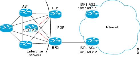
Master Controller Deployed with Two Border Routers
The master controller performs no routing functions. BGP is deployed on the border routers and internal peers in the OER-managed network. Each border router has an eBGP peering session with a different ISP. The eBGP peers (ISP border routers) are reachable through connected routes. Injected prefixes are advertised in the internal network through standard iBGP peering.
OER MC Configuration
The following example, starting in global configuration mode, shows the master controller configuration.
Router(config)# key chain OERRouter(config-keychain)# key 1Router(config-keychain-key)# key-string CISCORouter(config-keychain-key)# exitRouter(config)# oer masterRouter(config-oer-mc)# border 10.100.1.1 key-chain OERRouter(config-oer-mc-br)# interface Ethernet 0/0 externalRouter(config-oer-mc-br-if)# exitRouter(config-oer-mc-br)# interface Serial 1/1 internalRouter(config-oer-mc-br-if)# endRouter(config-oer-mc)# border 10.200.2.2 key-chain OERRouter(config-oer-mc-br)# interface Ethernet 2/2 externalRouter(config-oer-mc-br-if)# exitRouter(config-oer-mc-br)# interface Serial 3/3 internalRouter(config-oer-mc-br-if)# endBR1 Configuration
The following example, starting in global configuration mode, shows the configuration for BR1. eBGP peering is established with ISP1 (192.168.1.1 AS2). Standard community exchange and iBGP peering are established with BR2 (10.200.2.2) and internal peers (in the 10.150.1.0/24 network).
Router(config)# key chain OERRouter(config-keychain)# key 1Router(config-keychain-key)# key-string CISCORouter(config-keychain-key)# exitRouter(config-keychain)# exitRouter(config)# oer borderRouter(config-oer-br)# master 172.16.1.1 key-chain OERRouter(config-oer-br)# local Serial 1/1Router(config-oer-br)# exitRouter(config)# router bgp 1Router(config-router)# neighbor 192.168.1.1 remote-as 2Router(config-router)# neighbor 10.200.2.2 remote-as 1Router(config-router)# neighbor 10.150.1.1 remote-as 1Router(config-router)# neighbor 10.150.1.2 remote-as 1Router(config-router)# neighbor 10.150.1.3 remote-as 1Router(config-router)# address-family ipv4 unicastRouter(config-router-af)# neighbor 192.168.1.1 activateRouter(config-router-af)# neighbor 10.200.2.2 activateRouter(config-router-af)# neighbor 10.200.2.2 send-community standardRouter(config-router-af)# neighbor 10.150.1.1 activateRouter(config-router-af)# neighbor 10.150.1.1 send-community standardRouter(config-router-af)# neighbor 10.150.1.2 activateRouter(config-router-af)# neighbor 10.150.1.2 send-community standardRouter(config-router-af)# neighbor 10.150.1.3 activateRouter(config-router-af)# neighbor 10.150.1.3 send-community standardRouter(config-router-af)# endBR2 Configuration
The following example, starting in global configuration mode, shows the configuration for BR2. eBGP peering is established with ISP2 (192.168.2.2 AS1). Standard community exchange and iBGP peering is established with BR2 (10.100.1.1) and internal peers (in the 10.150.1.0/24 network).
Router(config)# key chain OERRouter(config-keychain)# key 1Router(config-keychain-key)# key-string CISCORouter(config-keychain-key)# endRouter(config)# oer borderRouter(config-oer-br)# master 172.16.1.1 key-chain OERRouter(config-oer-br)# local Serial 1/1Router(config-oer-br)# exitRouter(config)# router bgp 1Router(config-router)# neighbor 192.168.2.2 remote-as 3Router(config-router)# neighbor 10.100.1.1 remote-as 1Router(config-router)# neighbor 10.150.1.1 remote-as 1Router(config-router)# neighbor 10.150.1.2 remote-as 1Router(config-router)# neighbor 10.150.1.3 remote-as 1Router(config-router)# address-family ipv4 unicastRouter(config-router-af)# neighbor 192.168.2.2 activateRouter(config-router-af)# neighbor 10.200.2.2 activateRouter(config-router-af)# neighbor 10.200.2.2 send-community standardRouter(config-router-af)# neighbor 10.150.1.1 activateRouter(config-router-af)# neighbor 10.150.1.1 send-community standardRouter(config-router-af)# neighbor 10.150.1.2 activateRouter(config-router-af)# neighbor 10.150.1.2 send-community standardRouter(config-router-af)# neighbor 10.150.1.3 activateRouter(config-router-af)# neighbor 10.150.1.3 send-community standardRouter(config-router-af)# endInternal Peer Configuration
The following example, starting in global configuration mode, shows the internal peer configuration. Standard full-mesh iBGP peering is established with BR1 and BR2 and the internal peers in autonomous system 1.
Router(config)# router bgp 1Router(config-router)# neighbor 10.100.1.1 remote-as 1Router(config-router)# neighbor 10.200.2.2 remote-as 1Router(config-router)# neighbor 10.150.1.1 remote-as 1Router(config-router)# neighbor 10.150.1.2 remote-as 1Router(config-router)# neighbor 10.150.1.3 remote-as 1Router(config-router)# address-family ipv4 unicastRouter(config-router-af)# neighbor 10.100.1.1 activateRouter(config-router-af)# neighbor 10.100.1.1 send-community standardRouter(config-router-af)# neighbor 10.200.2.2 activateRouter(config-router-af)# neighbor 10.200.2.2 send-community standardRouter(config-router-af)# neighbor 10.150.1.1 activateRouter(config-router-af)# neighbor 10.150.1.1 send-community standardRouter(config-router-af)# neighbor 10.150.1.2 activateRouter(config-router-af)# neighbor 10.150.1.2 send-community standardRouter(config-router-af)# neighbor 10.150.1.3 activateRouter(config-router-af)# neighbor 10.150.1.3 send-community standardRouter(config-router-af)# endOER Master Controller and Border Router Process Deployed on a Single Router with a Second Border Router: Example
Figure 10 shows an OER-managed network with two border routers. BR1 is configured to run a master controller and border router process.
Figure 10 OER Master Controller and Border Router Process Deployed on a Single Router with a Second Border Router
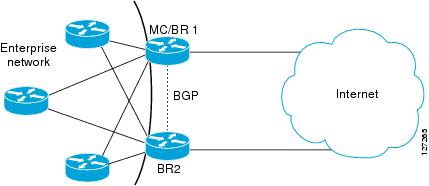
BR2 is configured as a border router. The internal network is running OSPF. Each border router peers with a different ISP. A static route to the egress interface is configured on each border router. The static routes are then redistributed into OSPF. Injected prefixes are advertised through static route redistribution.
BR1 Configuration: Master Controller and Border Router on a Single Router with Load Distribution Policy
The following example, starting in global configuration mode, shows the configuration of BR1. This router is configured to run both a master controller and a border router process. BR1 peers with ISP1. A traffic load distribution policy is configured under the master controller process that is applied to all exit links in the OER-managed network.
Router(config)# key chain OERRouter(config-keychain)# key 1Router(config-keychain-key)# key-string CISCORouter(config-keychain-key)# exitRouter(config-keychain)# exitRouter(config)# oer borderRouter(config-oer-br)# master 10.100.1.1 key-chain OERRouter(config-oer-br)# local Loopback 0Router(config-oer-br)# exitRouter(config)# oer masterRouter(config-oer-mc)# loggingRouter(config-oer-mc)# border 10.100.1.1 key-chain OERRouter(config-oer-mc-br)# interface Serial 0/0 externalRouter(config-oer-mc-br-if)# exitRouter(config-oer-mc-br)# interface Ethernet 1/1 internalRouter(config-oer-mc-br-if)# exitRouter(config-oer-mc-br)# exitRouter(config-oer-mc)# border 10.200.2.2 key-chain OERRouter(config-oer-mc-br)# interface Serial 2/2 externalRouter(config-oer-mc-br-if)# exitRouter(config-oer-mc-br)# interface Ethernet 3/3 internalRouter(config-oer-mc-br-if)# exitRouter(config-oer-mc-br)# exitRouter(config-oer-mc)# exitRouter(config)# ip route 0.0.0.0 0.0.0.0 Serial 0/0Router(config)# !Router(config)# route-map STATICRouter(config-route-map)# match tag 5000Router(config-route-map)# set metric -10Router(config-route-map)# exitRouter(config)# router ospf 1Router(config-router)# network 10.0.0.0 0.0.0.255 area 0Router(config-router)# redistribute static route-map STATIC subnetsRouter(config-router)# endBR2 Configuration
The following example, starting in global configuration mode, shows the configuration of BR2. This router is configured to run only a border router process.
Router(config)# key chain OERRouter(config-keychain)# key 1Router(config-keychain-key)# key-string CISCORouter(config-keychain-key)# exitRouter(config-keychain)# exitRouter(config)# oer borderRouter(config-oer-border)# master 10.100.1.1 key-chain OERRouter(config-oer-border)# local Ethernet3/3Router(config-oer-border)# exitRouter(config)# ip route 0.0.0.0 0.0.0.0 Serial 2/2Router(config)# !Router(config)# route-map STATIC permit 10Router(config-route-map)# match tag 5000Router(config-route-map)# set metric -10Router(config-route-map)# exitRouter(config)# router ospf 1Router(config-router)# network 10.0.0.0 0.255.255.255 area 0Router(config-router)# redistribute static route-map STATICRouter(config-router)# endInternal Peer Configuration
The following example, starting in global configuration mode, configures an OSPF routing process to establish peering with the border routers and internal peers. No redistribution is configured on the internal peers.
Router(config)# router ospf 1Router(config-router)# network 10.0.0.0 0.255.255.255 area 0Router(config-router)# redistribute static route-map STATIC subnetsRouter(config-router)# endOER Master Controller and Border Router Deployed on a Single Router: Example
Figure 11 shows a SOHO network in which the master controller and border router process are set up on a single router.
Figure 11 OER Deployed on a Single Router in a SOHO Configuration
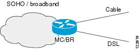
The router connects the SOHO network with two ISPs. OER is configured to learn prefixes based on highest outbound throughput and lowest delay. Prefixes with a response time longer than 80 milliseconds are out-of-policy and moved if the performance on the other link conforms to the policy.
Master Controller and Border Router Configuration on a Single Router
The following example, starting in global configuration mode, shows an OER master controller and border router process deployed on a single router:
Router(config)# key chain OERRouter(config-keychain)# key 1Router(config-keychain-key)# key-string KEYSTRING2Router(config-keychain-key)# exitRouter(config-keychain)# exitRouter(config)# oer borderRouter(config)# loggingRouter(config-oer-br)# master 10.100.1.1 key-chain OERRouter(config-oer-br)# local Loopback 0Router(config-oer-br)# exitRouter(config)# oer masterRouter(config-oer-mc)# loggingRouter(config-oer-mc)# border 10.100.1.1 key-chain OERRouter(config-oer-mc-br)# interface Ethernet 0/0 externalRouter(config-oer-mc-br-if)# exitRouter(config-oer-mc-br)# interface Ethernet 1/1 externalRouter(config-oer-mc-br-if)# exitRouter(config-oer-mc-br)# interface Ethernet 2/2 internalRouter(config-oer-mc-br-if)# exitRouter(config-oer-mc-br)# exitRouter(config-oer-mc)# exitRouter(config)# ip route 0.0.0.0 0.0.0.0 Ethernet 0/0Router(config)# ip route 0.0.0.0 0.0.0.0 Ethernet 1/1Router(config)# endRegistering an Application Interface Provider and Configuring Host Devices: Example
The following configuration example shows how to register a provider on a master controller. In this example, more than one provider is configured, so the priority is set for each provider. For the single host device configured for provider 1, no priority is set and the default priority value of 65535 is assigned giving this host device a lower priority than both the host devices configured for provider 2. After the provider is registered and an application on a host device initiates a session, some show commands can be entered on the master controller to help you track provider activity.
Router(config)# oer masterRouter(config-oer-mc)# api provider 1 priority 3000Router(config-oer-mc-api-provider)# host-address 10.1.2.2 key-chain OER_HOSTRouter(config-oer-mc-api-provider)# exitRouter(config-oer-mc)# api provider 2 priority 4000Router(config-oer-mc-api-provider)# host-address 10.2.2.2 key-chain OER_HOST priority 3000Router(config-oer-mc-api-provider)# host-address 10.2.2.3 key-chain OER_HOST priority 4000Router(config-oer-mc-api-provider)# end!Router# show oer api provider detailRouter# show oer master policy dynamicRouter# show oer master prefix 10.1.1.0/24 reportWhere to Go Next
Now that your OER network components are set up, you should read through the other modules in the following order:
•
•
•
•
After you understand the various OER phases, review the OER solutions modules that are listed under "Related Documents" section.
Additional References
The following sections provide references related to setting up OER network components.
Related Documents
Cisco OER technology overview
OER solution module: voice traffic optimization using OER active probes
OER solution module: configuring VPN IPsec/GRE tunnel interfaces as OER-managed exit links
"Configuring VPN IPsec/GRE Tunnel Interfaces As OER-Managed Exit Links" module
Cisco OER commands: complete command syntax, command mode, command history, defaults, usage guidelines and examples
Cisco IOS Optimized Edge Routing Command Reference, Release 12.4T
Cisco OER CPU and memory and test information
Cisco Optimized Edge Routing Cpu And Memory Performance Tests
Key Chain Authentication: information about authentication key configuration and management in Cisco IOS software
"Managing Authentication Keys" section of the Cisco IOS IP Routing Protocols Configuration Guide, Release 12.4
IP Routing Protocol commands
•
•
IP Routing Protocol configuration tasks
Cisco IOS IP Routing Protocols Configuration Guide, Release 12.4
Standards
No new or modified standards are supported, and support for existing standards has not been modified.
—
MIBs
RFCs
No new or modified RFCs are supported, and support for existing RFCs has not been modified.
—
Technical Assistance
Feature Information for Setting Up OER Network Components
Table 3 lists the features in this module and provides links to specific configuration information. Only features that were introduced or modified in Cisco IOS Release 12.3(8)T, 12.2(33)SRB, or a later release appear in the table.
For information on a feature in this technology that is not documented here, see the "Cisco IOS Optimized Edge Routing Features Roadmap."
Not all commands may be available in your Cisco IOS software release. For release information about a specific command, see the command reference documentation.
Use Cisco Feature Navigator to find information about platform support and software image support. Cisco Feature Navigator enables you to determine which Cisco IOS and Catalyst OS software images support a specific software release, feature set, or platform. To access Cisco Feature Navigator, go to http://www.cisco.com/go/cfn. An account on Cisco.com is not required.
Note
Table 3 Feature Information for Setting Up OER Network Components
Optimized Edge Routing
12.3(8)T
12.2(33)SRBOER was introduced.
Automatic Port Configuration 1
12.3(11)T
12.2(33)SRBSupport for automatic port configuration was introduced. Communication between the master controller and border router is automatically carried over port 3949 when connectivity is established. Port 3949 is registered with IANA for OER communication. Manual port number configuration is required only if you are running Cisco IOS Release 12.3(8)T or if you need to configure OER communication to use a dynamic port number.
The following section provides information about this feature:
•
No commands were introduced by this feature.
Support for NAT and Static Routing2
12.3(14)T
12.2(33)SRBSupport to allow OER to control traffic class routing using static routing in networks using NAT.
The following sections provide information about this feature:
•
•
The following command was modified by this feature: ip nat inside source.
Support for VLAN Interfaces3
12.3(14)T
12.2(33)SRBSupport to configure a VLAN interface as an internal interface was introduced.
The following section provides information about this feature:
•
No commands were introduced by this feature.
Application Performance Routing: PBR
12.4(2)T
12.2(33)SRBThe Application Performance Routing: PBR feature introduces the capability to optimize IP traffic based on the type of application that is carried by the monitored prefix. Independent policy configuration is applied to the subset (application) of traffic. The ability to configure a Cisco router as an interim border router to allow a border router to be more than one hop away from the master controller, was also introduced.
The following sections provide information about this feature:
•
•
•
The following commands were introduced or modified by this feature: debug oer border pbr, debug oer master prefix, match ip address (OER), show oer master active-probes, and show oer master appl.
Performance Routing - Application Interface
12.4(15)T
The Performance Routing - Application Interface feature introduces support for an OER application interface. The application interface defines the mode of communication and messaging between applications and the network for the purpose of optimizing the traffic associated with the applications. A provider must be registered with an OER master controller before the application can interface with OER. Host devices in the provider network running an application that communicates with OER using the application interface must also be configured at an OER master controller with an IP address and key chain password.
The following sections provide information about this feature:
•
•
•
The following commands were introduced or modified by this feature: api provider, debug oer api, host-address, show oer api provider, show oer master policy, and show oer master prefix.
OER Border Router Only Functionality
12.2(33)SXH
In Cisco IOS Release 12.2(33)SXH support for using a Cisco Catalyst 6500 series switch as an OER border router was introduced. Only border router functionality is included in the Cisco IOS Release 12.2(33)SXH images; no master controller configuration is available. The master controller that communicates with the Cisco Catalyst 6500 series switch being used as a border router must be a router running Cisco IOS Release 12.4(6)T or a later release. The OER master controller software has been modified to handle the limited functionality supported by the Cisco Catalyst 6500 border routers. Using the Route Processor (RP), the Catalyst 6500 border routers can capture throughput statistics only for a traffic class compared to the delay, loss, unreachability, and throughput statistics collected by non-Catalyst 6500 border routers. A master controller automatically detects the limited capabilities of the Catalyst 6500 border routers and downgrades other border routers to capture only the throughput statistics for traffic classes. By ignoring other types of statistics, the master controller is presented with a uniform view of the border router functionality.
The following sections provide information about this feature:
•
•
The following command was introduced or modified by this feature: show oer border passive cache.
1 This is a minor enhancement. Minor enhancements are not typically listed in Feature Navigator.
2 This is a minor enhancement. Minor enhancements are not typically listed in Feature Navigator.
3 This is a minor enhancement. Minor enhancements are not typically listed in Feature Navigator.

Any Internet Protocol (IP) addresses used in this document are not intended to be actual addresses. Any examples, command display output, and figures included in the document are shown for illustrative purposes only. Any use of actual IP addresses in illustrative content is unintentional and coincidental.
© 2007 Cisco Systems, Inc. All rights reserved.
 Feedback
Contact Cisco
- Open a Support Case

- (Requires a Cisco Service Contract)
This Document Applies to These Products
- Collaboration Endpoints - Retired Products
- Conferencing - Retired Products
- Contact Center - Retired Products
- Optical Networking - Retired Products
- Routers - Retired Products
- Security - Retired Products
- Servers - Unified Computing (UCS) Retired Products
- Storage Networking Retired Products
- Switches - Retired Products
- Video - Retired Products
- Wireless - Retired Products