- IPv6 Quality of Service
- IPv6 QoS: MQC Packet Classification
- Packet Classification Based on Layer 3 Packet Length
- IPv6 QoS: MQC Packet Marking/Remarking
- Marking Network Traffic
- Classifying Network Traffic
- Class-Based Ethernet CoS Matching and Marking
- QoS Group Match and Set for Classification and Marking
- Quality of Service for VPNs
- QoS Match VLAN
- Inbound Policy Marking for dVTI
- QoS Tunnel Marking for GRE Tunnels
- QoS for dVTI
- Classifying and Marking MPLS EXP
- Finding Feature Information
- Prerequisites for Marking Network Traffic
- Restrictions for Marking Network Traffic
- Information About Marking Network Traffic
- How to Mark Network Traffic
- Configuration Examples for Marking Network Traffic
- Additional References for Marking Network Traffic
- Feature Information for Marking Network Traffic
Marking Network Traffic
Marking network traffic allows you to set or modify the attributes for traffic (that is, packets) belonging to a specific class or category. When used in conjunction with network traffic classification, marking network traffic is the foundation for enabling many quality of service (QoS) features on your network. This module contains conceptual information and the configuration tasks for marking network traffic.
- Finding Feature Information
- Prerequisites for Marking Network Traffic
- Restrictions for Marking Network Traffic
- Information About Marking Network Traffic
- How to Mark Network Traffic
- Configuration Examples for Marking Network Traffic
- Additional References for Marking Network Traffic
- Feature Information for Marking Network Traffic
Finding Feature Information
Your software release may not support all the features documented in this module. For the latest caveats and feature information, see Bug Search Tool and the release notes for your platform and software release. To find information about the features documented in this module, and to see a list of the releases in which each feature is supported, see the feature information table at the end of this module.
Use Cisco Feature Navigator to find information about platform support and Cisco software image support. To access Cisco Feature Navigator, go to www.cisco.com/go/cfn. An account on Cisco.com is not required.
Prerequisites for Marking Network Traffic
In order to mark network traffic, Cisco Express Forwarding must be configured on both the interface receiving the traffic and the interface sending the traffic.
Restrictions for Marking Network Traffic
Traffic marking can be configured on an interface, a subinterface, or an ATM permanent virtual circuit (PVC). Marking network traffic is not supported on the following interfaces:
- ATM switched virtual circuit (SVC)
- Fast EtherChannel
- PRI
- Tunnel
Information About Marking Network Traffic
- Purpose of Marking Network Traffic
- Benefits of Marking Network Traffic
- Two Methods for Marking Traffic Attributes
- Method for Marking Traffic Attributes
- MQC and Network Traffic Marking
- Traffic Classification Compared with Traffic Marking
Purpose of Marking Network Traffic
Traffic marking is a method used to identify certain traffic types for unique handling, effectively partitioning network traffic into different categories.
After the network traffic is organized into classes by traffic classification, traffic marking allows you to mark (that is, set or change) a value (attribute) for the traffic belonging to a specific class. For instance, you may want to change the class of service (CoS) value from 2 to 1 in one class, or you may want to change the differentiated services code point (DSCP) value from 3 to 2 in another class. In this module, these values are referred to as attributes.
Attributes that can be set and modified include the following:
- Cell loss priority (CLP) bit
- CoS value of an outgoing packet
- Discard-class value
- Discard eligible (DE) bit setting in the address field of a Frame Relay frame
- DSCP value in the type of service (ToS) byte
- MPLS EXP field value in the topmost label on an input or output interface
- Multiprotocol Label Switching (MPLS) experimental (EXP) field on all imposed label entries
- Precedence value in the packet header
- QoS group identifier (ID)
- ToS bits in the header of an IP packet
Benefits of Marking Network Traffic
Improved Network Performance
Traffic marking allows you to fine-tune the attributes for traffic on your network. This increased granularity helps single out traffic that requires special handling and, thus, helps to achieve optimal application performance.
Traffic marking allows you to determine how traffic will be treated, based on how the attributes for the network traffic are set. It allows you to segment network traffic into multiple priority levels or classes of service based on those attributes, as follows:
- Traffic marking is often used to set the IP precedence or IP DSCP values for traffic entering a network. Networking devices within your network can then use the newly marked IP precedence values to determine how traffic should be treated. For example, voice traffic can be marked with a particular IP precedence or DSCP, and a queueing mechanism can then be configured to put all packets of that mark into a priority queue.
- Traffic marking can be used to identify traffic for any class-based QoS feature (any feature available in policy-map class configuration mode, although some restrictions exist).
-
Traffic marking can be used to assign traffic to a QoS group within a device. The device can use the QoS groups to determine how to prioritize traffic for transmission. The QoS group value is usually used for one of the two following reasons: - If a packet (for instance, in a traffic flow) that needs to be marked to differentiate user-defined QoS services is leaving a device and entering a switch, the device can set the CoS value of the traffic, because the switch can process the Layer 2 CoS header marking. Alternatively, the Layer 2 CoS value of the traffic leaving a switch can be mapped to the Layer 3 IP or MPLS value.
Two Methods for Marking Traffic Attributes
There are two methods for specifying and marking traffic attributes:
- You can specify and mark the traffic attribute by using a set command.
With this method, you configure individual set commands for the traffic attribute that you want to mark.
- You can specify and mark the traffic attribute by creating a mapping table (called a "table map").
With this method, you configure the traffic attributes that you want to mark once in a table map and then the markings can be propagated throughout the network.
These methods are further described in the sections that follow.
Method One Using a set Command
You specify the traffic attribute that you want to change with a setcommand configured in a policy map. The table below lists the available setcommands and the corresponding attribute. The table also includes the network layer and the network protocol typically associated with the traffic attribute.
| set Commands1 |
Traffic Attribute |
Network Layer |
Protocol |
|---|---|---|---|
| set atm-clp |
CLP bit |
Layer 2 |
ATM |
| set cos |
Layer 2 CoS value of the outgoing traffic |
Layer 2 |
ATM, Frame Relay |
| set discard-class |
discard-class value |
Layer 2 |
ATM, Frame Relay |
| set dscp |
DSCP value in the ToS byte |
Layer 3 |
IP |
| set fr-de |
DE bit setting in the address field of a Frame Relay frame |
Layer 2
|
Frame Relay
|
| set ip tos (route-map) |
ToS bits in the header of an IP packet |
Layer 3 |
IP |
| set mpls experimental imposition |
MPLS EXP field on all imposed label entries |
Layer 3 |
MPLS |
| set mpls experimental topmost |
MPLS EXP field value in the topmost label on either an input or an output interface |
Layer 3 |
MPLS |
| set precedence |
Precedence value in the packet header |
Layer 3 |
IP |
| set qos-group |
QoS group ID |
Layer 3 |
IP, MPLS |
If you are using individual set commands, those set commands are specified in a policy map. The following is a sample policy map configured with one of the set commands listed in the table above. In this sample configuration, the set atm-clpcommand has been configured in the policy map (policy1) to mark the CLP attribute.
 policy-map policy1
  class class1
   set atm-clp
   end
Method Two Using a Table Map
You can create a table map that can be used to mark traffic attributes. A table map is a kind of two-way conversion chart that lists and maps one traffic attribute to another. A table map supports a many-to-one type of conversion and mapping scheme. The table map establishes a to-from relationship for the traffic attributes and defines the change to be made to the attribute. That is, an attribute is set to one value that is taken from another value. The values are based on the specific attribute being changed. For instance, the Precedence attribute can be a number from 0 to 7, while the DSCP attribute can be a number from 0 to 63.
The following is a sample table map configuration:
table-map table-map1
map from 0 to 1
map from 2 to 3
exit
The table below lists the traffic attributes for which a to-from relationship can be established using the table map.
| The "To" Attribute |
The "From" Attribute |
|---|---|
| Precedence |
CoS |
| QoS group |
|
| DSCP |
CoS |
| QoS group |
|
| CoS |
Precedence |
| DSCP |
|
| QoS group |
Precedence |
| DSCP |
|
| MPLS EXP topmost |
|
| MPLS EXP topmost |
QoS group |
| MPLS EXP imposition |
Precedence |
| DSCP |
Once the table map is created, you configure a policy map to use the table map. In the policy map, you specify the table map name and the attributes to be mapped by using the table keyword and the table-map-name argument with one of the commands listed in the table below.
| Command Used in Policy Maps |
Maps These Attributes |
|---|---|
| set cos dscp table table-map-name |
CoS to DSCP |
| set cos precedence table table-map-name |
CoS to Precedence |
| set dscp cos table table-map-name |
DSCP to CoS |
| set dscp qos-group table table-map-name |
DSCP to qos-group |
| set mpls experimental imposition dscp table table-map-name |
MPLS EXP imposition to DSCP |
| set mpls experimental imposition precedence table table-map-name |
MPLS EXP imposition to precedence |
| set mpls experimental topmost qos-group table table-map-name |
MPLS EXP topmost to QoS-group |
| set precedence cos table table-map-name |
Precedence to CoS |
| set precedence qos-group table table-map-name |
Precedence to QoS-group |
| set qos-group dscp table table-map-name |
QoS-group to DSCP |
| set qos-group mpls exp topmost table table-map-name |
QoS-group to MPLS EXP topmost |
| set qos-group precedence table table-map-name |
QoS-group to Precedence |
The following is an example of a policy map (policy2) configured to use the table map (table-map1) created earlier:
policy map policy2
class class-default
set cos dscp table table-map1
exit
In this example, a mapping relationship was created between the CoS attribute and the DSCP attribute as defined in the table map.
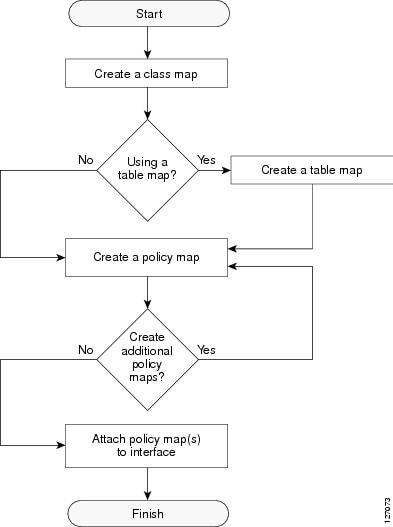
Traffic Marking Procedure Flowchart
The figure below illustrates the order of the procedures for configuring traffic marking.
Method for Marking Traffic Attributes
You specify and mark the traffic attribute that you want to change by using a set command configured in a policy map.
With this method, you configure individual set commands for the traffic attribute that you want to mark.
Using a set Command
The table below lists the available set commands and the corresponding attribute. The table below also includes the network layer and the network protocol typically associated with the traffic attribute.
| set Commands2 |
Traffic Attribute |
Network Layer |
Protocol |
|---|---|---|---|
| set cos |
Layer 2 CoS value of the outgoing traffic |
Layer 2 |
ATM, Frame Relay |
| set discard-class |
discard-class value |
Layer 2 |
ATM, Frame Relay |
| set dscp |
DSCP value in the ToS byte |
Layer 3 |
IP |
| set fr-de |
DE bit setting in the address field of a Frame Relay frame |
Layer 2
|
Frame Relay
|
| set ip tos (route-map) |
ToS bits in the header of an IP packet |
Layer 3 |
IP |
| set mpls experimental imposition |
MPLS EXP field on all imposed label entries |
Layer 3 |
MPLS |
| set mpls experimental topmost |
MPLS EXP field value in the topmost label on an input or output interface |
Layer 3 |
MPLS |
| set precedence |
Precedence value in the packet header |
Layer 3 |
IP |
| set qos-group |
QoS group ID |
Layer 3 |
IP, MPLS |
If you are using individual set commands, those set commands are specified in a policy map. The following is a sample policy map configured with one of the set commands listed in the table above. In this sample configuration, the set cos command has been configured in the policy map (policy1) to mark the CoS value.
 policy-map policy1
  class class1
   set cos 1
   end
For information on configuring a policy map, see the “Creating a Policy Map for Applying a QoS Feature to Network Traffic” section.
The final task is to attach the policy map to the interface. For information on attaching the policy map to the interface, see the “Attaching the Policy Map to an Interface” section.
MQC and Network Traffic Marking
To configure network traffic marking, you use the Modular QoS CLI (MQC).
The MQC is a CLI structure that allows you to complete the following tasks:
- Specify the matching criteria used to define a traffic class.
- Create a traffic policy (policy map). The traffic policy defines the QoS policy actions to be taken for each traffic class.
- Apply the policy actions specified in the policy map to an interface, subinterface, or ATM PVC by using the service-policy command.
Traffic Classification Compared with Traffic Marking
Traffic classification and traffic marking are closely related and can be used together. Traffic marking can be viewed as an additional action, specified in a policy map, to be taken on a traffic class.
Traffic classification allows you to organize into traffic classes on the basis of whether the traffic matches specific criteria. For example, all traffic with a CoS value of 2 is grouped into one class, and traffic with a DSCP value of 3 is grouped into another class. The match criteria are user-defined.
After the traffic is organized into traffic classes, traffic marking allows you to mark (that is, set or change) an attribute for the traffic belonging to that specific class. For instance, you may want to change the CoS value from 2 to 1, or you may want to change the DSCP value from 3 to 2.
The match criteria used by traffic classification are specified by configuring a match command in a class map. The marking action taken by traffic marking is specified by configuring a set command in a policy map. These class maps and policy maps are configured using the MQC.
The table below compares the features of traffic classification and traffic marking.
| Feature |
Traffic Classification |
Traffic Marking |
|---|---|---|
| Goal |
Groups network traffic into specific traffic classes on the basis of whether the traffic matches the user-defined criterion. |
After the network traffic is grouped into traffic classes, modifies the attributes for the traffic in a particular traffic class. |
| Configuration Mechanism |
Uses class maps and policy maps in the MQC. |
Uses class maps and policy maps in the MQC. |
| CLI |
In a class map, uses match commands (for example, match cos) to define the traffic matching criteria. |
Uses the traffic classes and matching criteria specified by traffic classification. In addition, uses set commands (for example, set cos) in a policy map to modify the attributes for the network traffic. |
How to Mark Network Traffic
- Creating a Class Map for Marking Network Traffic
- Creating a Table Map for Marking Network Traffic
- Creating a Policy Map for Applying a QoS Feature to Network Traffic
- Attaching the Policy Map to an Interface
Creating a Class Map for Marking Network Traffic
 Note |
The match protocol command is included in the steps below. The match protocol command is just an example of one of the match commands that can be used. See the command documentation for a complete list of match commands. |
1. enable
2. configure terminal
3. class-map class-map-name [match-all | match-any]
4. match protocol protocol-name
5. end
DETAILED STEPS
Creating a Table Map for Marking Network Traffic
Note |
If you are not using a table map, skip this procedure and advance to the “Creating a Policy Map for Applying a QoS Feature to Network Traffic”. |
1. enable
2. configure terminal
3. table-map table-map-name map from from-value to to-value [default default-action-or-value]
4. end
DETAILED STEPS
| Command or Action | Purpose | |
|---|---|---|
| Step 1 | enable Example: Device> enable |
Enables privileged EXEC mode. |
| Step 2 | configure terminal Example: Device# configure terminal |
Enters global configuration mode. |
| Step 3 | table-map table-map-name map from from-value to to-value [default default-action-or-value] Example: Example: Device(config)# table-map table-map1 map from 2 to 1 |
Creates a table map using the specified name and enters tablemap configuration mode.
|
| Step 4 | end Example: Device(config-tablemap)# end |
(Optional) Exits tablemap configuration mode and returns to privileged EXEC mode.
|
Creating a Policy Map for Applying a QoS Feature to Network Traffic
- Before modifying the encapsulation type from IEEE 802.1 Q to ISL, or vice versa, on a subinterface, detach the policy map from the subinterface. After changing the encapsulation type, reattach the policy map.
- A policy map containing the set qos-group command can only be attached as an input traffic policy. QoS group values are not usable for traffic leaving a device.
- A policy map containing the set cos command can only be attached as an output traffic policy.
1. enable
2. configure terminal
3. policy-map policy-map-name
4. class {class-name | class-default}
5. set cos cos-value
6. end
7. show policy-map
8. show policy-map policy-map class class-name
DETAILED STEPS
| Command or Action | Purpose | |||
|---|---|---|---|---|
| Step 1 | enable Example: Device> enable |
Enables privileged EXEC mode. |
||
| Step 2 | configure terminal Example: Device# configure terminal |
Enters global configuration mode. |
||
| Step 3 | policy-map policy-map-name Example: Device(config)# policy-map policy1 |
Specifies the name of the policy map and enters policy-map configuration mode. |
||
| Step 4 | class {class-name | class-default} Example: Device(config-pmap)# class class1 |
Specifies the name of the class whose policy you want to create and enters policy-map class configuration mode. This class is associated with the class map created earlier. |
||
| Step 5 | set cos cos-value Example: Device(config-pmap-c)# set cos 2 |
(Optional) Sets the CoS value in the type of service (ToS) byte.
|
||
| Step 6 | end Example: Device(config-pmap-c)# end |
Returns to privileged EXEC mode. |
||
| Step 7 | show policy-map Example: Device# show policy-map |
(Optional) Displays all configured policy maps. |
||
| Step 8 | show policy-map policy-map class class-name Example: Device# show policy-map policy1 class class1 |
(Optional) Displays the configuration for the specified class of the specified policy map. |
What to Do Next
Create and configure as many policy maps as you need for your network. To create and configure additional policy maps, repeat the steps in the “Creating a Policy Map for Applying a QoS Feature to Network Traffic” section. Then attach the policy maps to the appropriate interface, following the instructions in the “Attaching the Policy Map to an Interface” section.
Attaching the Policy Map to an Interface
Note |
Depending on the needs of your network, policy maps can be attached to an interface, a subinterface, or an ATM permanent virtual circuit (PVC). |
1. enable
2. configure terminal
3. interface type number [name-tag]
4. pvc [name] vpi/vci [ilmi | qsaal | smds | l2transport]
5. exit
6. service-policy {input | output} policy-map-name
7. end
8. show policy-map interface type number
DETAILED STEPS
| Command or Action | Purpose | |||
|---|---|---|---|---|
| Step 1 | enable Example: Device> enable |
Enables privileged EXEC mode. |
||
| Step 2 | configure terminal Example: Device# configure terminal |
Enters global configuration mode. |
||
| Step 3 | interface type number [name-tag] Example: Device(config)# interface serial4/0/0 |
Configures an interface type and enters interface configuration mode. |
||
| Step 4 | pvc [name] vpi/vci [ilmi | qsaal | smds | l2transport] Example: Device(config-if)# pvc cisco 0/16 |
(Optional) Creates or assigns a name to an ATM permanent virtual circuit (PVC), specifies the encapsulation type on an ATM PVC, and enters ATM virtual circuit configuration mode.
|
||
| Step 5 | exit Example: Device(config-atm-vc)# exit |
(Optional) Returns to interface configuration mode.
|
||
| Step 6 | service-policy {input | output} policy-map-name Example: Device(config-if)# service-policy input policy1 |
Attaches a policy map to an input or output interface.
|
||
| Step 7 | end Example: Device(config-if)# end |
Returns to privileged EXEC mode. |
||
| Step 8 | show policy-map interface type number Example: Device# show policy-map interface serial4/0/0 |
(Optional) Displays the traffic statistics of all classes that are configured for all service policies either on the specified interface or subinterface or on a specific PVC on the interface. |
Configuration Examples for Marking Network Traffic
- Example: Creating a Class Map for Marking Network Traffic
- Example Creating a Policy Map for Applying a QoS Feature to Network Traffic
- Example: Attaching the Policy Map to an Interface
Example: Creating a Class Map for Marking Network Traffic
The following is an example of creating a class map to be used for marking network traffic. In this example, a class called class1 has been created. Ttraffic with a protocol type of FTP will be put in this class.
Device> enable
Device# configure terminal
Device(config)# class-map class1
Device(config-cmap)# match protocol ftp
Device(config-cmap)# end
Example Creating a Policy Map for Applying a QoS Feature to Network Traffic
The following is an example of creating a policy map to be used for traffic classification. In this example, a policy map called policy1 has been created, and the bandwidth command has been configured for class1. The bandwidth command configures the QoS feature CBWFQ.
Router> enable
Router# configure terminal
Router(config)# policy-map policy1
Router(config-pmap)# class class1
Router(config-pmap-c)# bandwidth percent 50
Router(config-pmap-c)# end
Router#
show policy-map policy1 class class1
Router# exit
Note |
This example uses the bandwidth command. The bandwidth command configures the QoS feature class-based weighted fair queuing (CBWFQ). CBWFQ is just an example of a QoS feature that can be configured. Use the appropriate command for the QoS feature that you want to use. |
Example: Attaching the Policy Map to an Interface
The following is an example of attaching the policy map to the interface. In this example, the policy map called policy1 has been attached in the input direction to the serial interface 4/0/0.
Device> enable
Device# configure terminal
Device(config)# interface serial4/0/0
Device(config-if)# service-policy input policy1
Device(config-if)# end
Additional References for Marking Network Traffic
Related Documents
Related Topic |
Document Title |
|---|---|
| Cisco commands |
|
| QoS commands: complete command syntax, command modes, command history, defaults, usage guidelines, and examples |
Cisco IOS Quality of Service Solutions Command Reference |
| MQC |
“Applying QoS Features Using the MQC” module |
| Classifying network traffic |
“Classifying Network Traffic” module |
Technical Assistance
Description |
Link |
|---|---|
| The Cisco Support and Documentation website provides online resources to download documentation, software, and tools. Use these resources to install and configure the software and to troubleshoot and resolve technical issues with Cisco products and technologies. Access to most tools on the Cisco Support and Documentation website requires a Cisco.com user ID and password. |
Feature Information for Marking Network Traffic
The following table provides release information about the feature or features described in this module. This table lists only the software release that introduced support for a given feature in a given software release train. Unless noted otherwise, subsequent releases of that software release train also support that feature.
Use Cisco Feature Navigator to find information about platform support and Cisco software image support. To access Cisco Feature Navigator, go to www.cisco.com/go/cfn. An account on Cisco.com is not required.
| Feature Name |
Software Releases |
Feature Configuration Information |
|---|---|---|
| Class-Based Marking |
12.2(2)T Cisco IOS XE Release 2.1 Cisco IOS XE Release 2.2 Cisco IOS XE Release 3.2SE |
The Class-Based Packet Marking feature provides a user-friendly command-line interface (CLI) for efficient packet marking by which users can differentiate packets. This feature was implemented on Cisco ASR 1000 Series Routers. This feature was integrated into Cisco IOS XE Release 2.2. |
| Enhanced Packet Marking |
12.2(13)T Cisco IOS XE Release 3.9S |
The Enhanced Packet Marking feature allows you to map and convert the marking of a packet from one value to another by using a kind of conversion chart called a table map. The table map establishes an equivalency from one value to another. For example, the table map can map and convert the class of service (CoS) value of a packet to the precedence value of the packet. This value mapping can be propagated for use on the network, as needed. |
| QoS Packet Marking |
12.2(8)T Cisco IOS XE Release 2.1 Cisco IOS XE Release 2.2 Cisco IOS XE Release 3.5S Cisco IOS XE Release 3.9S |
The QoS Packet Marking feature allows you to mark packets by setting the IP precedence bit or the IP differentiated services code point (DSCP) in the Type of Service (ToS) byte, and to associate a local QoS group value with a packet. This feature was implemented on Cisco ASR 1000 Series Routers. This feature was integrated into Cisco IOS XE Software Release 2.2. In Cisco IOS XE Release 3.5S, support was added for the Cisco ASR 903 Router. In Cisco IOS XE Release 3.9S, support was added for the Cisco CSR 1000V. |
| IP DSCP marking for Frame-Relay PVC |
12.2(15)T Cisco IOS XE Release 2.1 |
This feature was implemented on Cisco ASR 1000 Series Routers. |
| PXF Based Frame Relay DE Bit Marking |
12.2(31)SB2 15.0(1)S |
PXF Based Frame Relay DE Bit Marking was integrated into the Cisco IOS Release 15.0(1)S release. |
 Feedback