- L2VPN Protocol-Based CLIs
- Any Transport over MPLS
- L2VPN Interworking
- L2VPN Pseudowire Preferential Forwarding
- L2VPN Multisegment Pseudowires
- MPLS Quality of Service
- QoS Policy Support on L2VPN ATM PVPs
- MPLS Pseudowire Status Signaling
- L2VPN VPLS Inter-AS Option B
- IEEE 802.1Q Tunneling (QinQ) for AToM
- Configuring the Managed IPv6 Layer 2 Tunnel Protocol Network Server
- L2VPN Pseudowire Redundancy
- Pseudowire Group Switchover
- L2VPN Pseudowire Switching
- Xconnect as a Client of BFD
- H-VPLS N-PE Redundancy for QinQ Access
- H-VPLS N-PE Redundancy for MPLS Access
- VPLS MAC Address Withdrawal
- Configuring Virtual Private LAN Services
- Routed Pseudo-Wire and Routed VPLS
- VPLS Autodiscovery BGP Based
- N:1 PVC Mapping to PWE with Nonunique VPIs
- QoS Policies for VFI Pseudowires
- VPLS BGP Signaling L2VPN Inter-AS Option A
- VPLS BGP Signaling L2VPN Inter-AS Option B
- Frame Relay over L2TPv3
- Loop-Free Alternate Fast Reroute with L2VPN
Contents
- L2VPN Multisegment Pseudowires
- Finding Feature Information
- Prerequisites for L2VPN Multisegment Pseudowires
- Restrictions for L2VPN Multisegment Pseudowires
- Information About L2VPN Multisegment Pseudowires
- L2VPN Pseudowire Defined
- L2VPN Multisegment Pseudowire Defined
- How to Configure L2VPN Multisegment Pseudowires
- Configuring L2VPN Multisegment Pseudowires
- Configuring L2VPN Multisegment Pseudowires using the commands associated with the L2VPN Protocol-Based CLIs feature
- Displaying Information About the L2VPN Multisegment Pseudowires
- Displaying Information About the L2VPN Multisegment Pseudowires using the commands associated with the L2VPN Protocol-Based CLIs feature
- Performing ping mpls and trace mpls Operations on the L2VPN Multisegment Pseudowires
- Additional References
- Feature Information for L2VPN Multisegment Pseudowires
L2VPN Multisegment Pseudowires
The L2VPN Multisegment Pseudowires feature enables you to configure two or more Layer 2 pseudowire segments that function as a single pseudowire. The L2VPN Multisegment Pseudowires feature span multiple cores or autonomous systems of the same or different carrier networks.
- Finding Feature Information
- Prerequisites for L2VPN Multisegment Pseudowires
- Restrictions for L2VPN Multisegment Pseudowires
- Information About L2VPN Multisegment Pseudowires
- How to Configure L2VPN Multisegment Pseudowires
- Additional References
- Feature Information for L2VPN Multisegment Pseudowires
Finding Feature Information
Your software release may not support all the features documented in this module. For the latest caveats and feature information, see Bug Search Tool and the release notes for your platform and software release. To find information about the features documented in this module, and to see a list of the releases in which each feature is supported, see the feature information table at the end of this module.
Use Cisco Feature Navigator to find information about platform support and Cisco software image support. To access Cisco Feature Navigator, go to www.cisco.com/go/cfn. An account on Cisco.com is not required.
Prerequisites for L2VPN Multisegment Pseudowires
Before configuring this feature, see the following documents:
- Any Transport over MPLS
- L2VPN Pseudowire Switching
- MPLS LSP Ping/Traceroute for LDP/TE, and LSP Ping for VCCV
- Pseudowire Setup and Maintenance Using the Label Distribution Protocol (LDP) (RFC 4447)
Restrictions for L2VPN Multisegment Pseudowires
- Only Mutliprotocol (MPLS) Layer 2 pseudowires are supported.
- Only manual configuration of the pseudowires (including S-PE and T-PE routers) is supported.
- The L2VPN Pseudowire Switching feature is supported for pseudowires advertised with FEC 128. FEC 129 is not supported.
- The S-PE router is limited to 1600 pseudowires.
Information About L2VPN Multisegment Pseudowires
L2VPN Pseudowire Defined
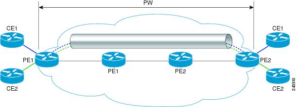
An L2VPN pseudowire (PW) is a tunnel established between two provider edge (PE) routers across the core carrying the Layer 2 payload encapsulated as MPLS data, as shown in the figure below. This helps carriers migrate from traditional Layer 2 networks such as Frame Relay and ATM to an MPLS core. In the L2VPN pseudowire shown in the figure, the PWs between two PE routers are located within the same autonomous system. Routers PE1 and PE2 are called terminating PE routers (T-PEs). Attachment circuits are bounded to the PW on these PE routers.
L2VPN Multisegment Pseudowire Defined
An L2VPN multisegment pseudowire (MS-PW) is a set of two or more PW segments that function as a single PW. It is also known as switched PW. MS-PWs span multiple cores or autonomous systems of the same or different carrier networks. A L2VPN MS-PW can include up to 254 PW segments.
The figure below is an example of a Multisegment Pseudowire topology.
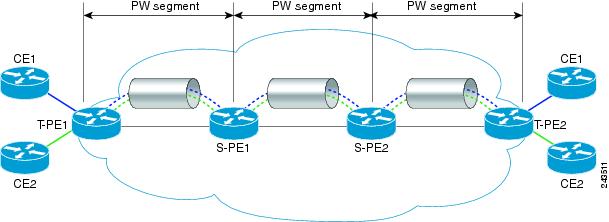
The end routers are called terminating PE routers (T-PEs), and the switching routers are called S-PE routers. The S-PE router terminates the tunnels of the preceding and succeeding PW segments in an MS-PW. The S-PE router can switch the control and data planes of the preceding and succeeding PW segments of the MS-PW. An MS-PW is declared to be up when all the single-segment PWs are up. For more information, see the L2VPN Pseudowire Switching document.
How to Configure L2VPN Multisegment Pseudowires
- Configuring L2VPN Multisegment Pseudowires
- Configuring L2VPN Multisegment Pseudowires using the commands associated with the L2VPN Protocol-Based CLIs feature
- Displaying Information About the L2VPN Multisegment Pseudowires
- Displaying Information About the L2VPN Multisegment Pseudowires using the commands associated with the L2VPN Protocol-Based CLIs feature
- Performing ping mpls and trace mpls Operations on the L2VPN Multisegment Pseudowires
Configuring L2VPN Multisegment Pseudowires
Perform the following steps on the S-PE routers to create L2VPN Multisegment Pseudowires.
1.
enable
2.
configure
terminal
3. mpls label protocol ldp
4.
mpls
ldp
router-id
interface
force
5.
pseudowire-class
name
6.
encapsulation
mpls
7.
switching
tlv
8.
exit
9.
l2
vfi
name
point-to-point
10.
description
string
11.
neighbor
ip-address
vcid
{
encapsulation
mpls
pw-class
pw-class-name}
DETAILED STEPS
Configuring L2VPN Multisegment Pseudowires using the commands associated with the L2VPN Protocol-Based CLIs feature
Perform this task on the S-PE routers to create L2VPN multisegment pseudowires.
1.
enable
2.
configure
terminal
3.
mpls
label protocol ldp
4.
mpls
ldp
router-id
interface
force
5.
interface pseudowire number
6.
encapsulation
mpls
7.
switching
tlv
8.
neighbor
peer-address vcid-value
9.
exit
10.
l2vpn
xconnect
context
context-name
11.
description
string
12.
member
ip-address
vcid
encapsulation
mpls
DETAILED STEPS
| Command or Action | Purpose | |||
|---|---|---|---|---|
| Step 1 |
enable
Example: Device> enable |
Enables privileged EXEC mode. | ||
| Step 2 |
configure
terminal
Example: Device# configure terminal |
Enters global configuration mode. | ||
| Step 3 |
mpls
label protocol ldp Example: Device(config)# mpls label protocol ldp |
Configures the use of Label Distribution Protocol (LDP) on all interfaces. | ||
| Step 4 |
mpls
ldp
router-id
interface
force
Example: Device(config)# mpls ldp router-id loopback0 force |
Specifies the preferred interface for determining the LDP router ID. | ||
| Step 5 |
interface pseudowire number
Example: Device(config)# interface pseudowire 1 |
Establishes an interface pseudowire with a value that you specify, and enters pseudowire configuration mode. | ||
| Step 6 |
encapsulation
mpls
Example: Device(config-pw)# encapsulation mpls |
Specifies the tunneling encapsulation. | ||
| Step 7 |
switching
tlv
Example: Device(config-pw)# switching tlv |
(Optional) Enables the advertisement of the switching point type-length variable (TLV) in the label binding. | ||
| Step 8 |
neighbor
peer-address vcid-value Example: Router(config-pw)# neighbor 10.0.0.1 123 |
Specifies the peer IP address and virtual circuit (VC) ID value of a Layer 2 VPN (L2VPN) pseudowire. | ||
| Step 9 |
exit
Example: Device(config-pw)# exit |
Exits pseudowire configuration mode. | ||
| Step 10 |
l2vpn
xconnect
context
context-name Example: Device(config)# l2vpn xconnect context con1 |
Creates a Layer 2 VPN (L2VPN) cross connect context and enters xconnect configuration mode.
| ||
| Step 11 |
description
string
Example: Device(config-xconnect)# description segment1 |
Provides a description of the switching provider edge router for a multisegment pseudowire. | ||
| Step 12 |
member
ip-address
vcid
encapsulation
mpls
Example: Device(config-xconnect)# member 10.10.10.10 1 encapsulation mpls |
Specifies the devices that form a point-to-point Layer 2 VPN (L2VPN) virtual forwarding interface (VFI) connection.
|
Displaying Information About the L2VPN Multisegment Pseudowires
1.
show
mpls
l2transport
binding
2.
show
mpls
l2transport
vc
detail
DETAILED STEPS
| Step 1 |
show
mpls
l2transport
binding
Use the show mpls l2transport binding command to display information about the pseudowire switching point, as shown in bold in the output. (In the following examples PE1 and PE4 are the T-PE routers.) Example:
Router# show mpls l2transport binding

  Destination Address: 10.1.1.1,  VC ID: 102
    Local Label:  17
        Cbit: 1,    VC Type: FastEthernet,    GroupID: 0
        MTU: 1500,   Interface Desc: n/a
        VCCV: CC Type: CW [1], RA [2], TTL [3]
              CV Type: LSPV [2]
    Remote Label: 16
        Cbit: 1,    VC Type: FastEthernet,    GroupID: 0
        MTU: 1500,   Interface Desc: n/a
        VCCV: CC Type: CW [1], RA [2], TTL [3]
              CV Type: LSPV [2]
        PW Switching Point:
             Vcid   local IP addr      remote IP addr      Description
             101    10.11.11.11        10.20.20.20         PW Switching Point PE3
             100    10.20.20.20        10.11.11.11         PW Switching Point PE2
|
| Step 2 |
show
mpls
l2transport
vc
detail
Use the show mpls l2transport vc detail command to display status of the pseudowire switching point. In the following example, the output (shown in bold) displays the segment that is the source of the fault of the multisegment pseudowire: Example:
Router# show mpls l2transport vc detail
Local interface: Se3/0/0 up, line protocol up, HDLC up
  Destination address: 12.1.1.1, VC ID: 100, VC status: down
    Output interface: Se2/0, imposed label stack {23}
    Preferred path: not configured
    Default path: active
    Next hop: point2point
  Create time: 00:03:02, last status change time: 00:01:41
  Signaling protocol: LDP, peer 10.1.1.1:0 up
    Targeted Hello: 10.1.1.4(LDP Id) -> 10.1.1.1, LDP is UP
    Status TLV support (local/remote)   : enabled/supported
      LDP route watch                   : enabled
      Label/status state machine        : established, LruRrd
      Last local dataplane   status rcvd: No fault
      Last local SSS circuit status rcvd: No fault
      Last local SSS circuit status sent: DOWN(PW-tx-fault)
      Last local  LDP TLV    status sent: No fault
      Last remote LDP TLV    status rcvd: DOWN(PW-tx-fault)
       PW Switching Point:
       Fault type  Vcid   local IP addr   remote IP addr   Description
       PW-tx-fault  101   10.1.1.1        10.1.1.1         S-PE2
      Last remote LDP ADJ    status rcvd: No fault
    MPLS VC labels: local 19, remote 23
    Group ID: local 0, remote 0
    MTU: local 1500, remote 1500
    Remote interface description:
  Sequencing: receive disabled, send disabled
  VC statistics:
    packet totals: receive 16, send 27
    byte totals:   receive 2506, send 3098
    packet drops:  receive 0, seq error 0, send 0
|
Displaying Information About the L2VPN Multisegment Pseudowires using the commands associated with the L2VPN Protocol-Based CLIs feature
1.
show
l2vpn
atom
binding
2.
show
l2vpn
atom
vc
detail
DETAILED STEPS
| Step 1 |
show
l2vpn
atom
binding
Use the show l2vpn atom binding command to display information about the pseudowire switching point, as shown in bold in the output. (In the following examples PE1 and PE4 are the T-PE routers.) Example:
Device# show l2vpn atom binding

  Destination Address: 10.1.1.1,  VC ID: 102
    Local Label:  17
        Cbit: 1,    VC Type: FastEthernet,    GroupID: 0
        MTU: 1500,   Interface Desc: n/a
        VCCV: CC Type: CW [1], RA [2], TTL [3]
              CV Type: LSPV [2]
    Remote Label: 16
        Cbit: 1,    VC Type: FastEthernet,    GroupID: 0
        MTU: 1500,   Interface Desc: n/a
        VCCV: CC Type: CW [1], RA [2], TTL [3]
              CV Type: LSPV [2]
        PW Switching Point:
             Vcid   local IP addr      remote IP addr      Description
             101    10.11.11.11        10.20.20.20         PW Switching Point PE3
             100    10.20.20.20        10.11.11.11         PW Switching Point PE2
|
| Step 2 |
show
l2vpn
atom
vc
detail
Use the show l2vpn atom vc detail command to display status of the pseudowire switching point. In the following example, the output (shown in bold) displays the segment that is the source of the fault of the multisegment pseudowire: Example:
Device# show l2vpn atom vc detail
Local interface: Se3/0/0 up, line protocol up, HDLC up
  Destination address: 12.1.1.1, VC ID: 100, VC status: down
    Output interface: Se2/0, imposed label stack {23}
    Preferred path: not configured
    Default path: active
    Next hop: point2point
  Create time: 00:03:02, last status change time: 00:01:41
  Signaling protocol: LDP, peer 10.1.1.1:0 up
    Targeted Hello: 10.1.1.4(LDP Id) -> 10.1.1.1, LDP is UP
    Status TLV support (local/remote)   : enabled/supported
      LDP route watch                   : enabled
      Label/status state machine        : established, LruRrd
      Last local dataplane   status rcvd: No fault
      Last local SSS circuit status rcvd: No fault
      Last local SSS circuit status sent: DOWN(PW-tx-fault)
      Last local  LDP TLV    status sent: No fault
      Last remote LDP TLV    status rcvd: DOWN(PW-tx-fault)
       PW Switching Point:
       Fault type  Vcid   local IP addr   remote IP addr   Description
       PW-tx-fault  101   10.1.1.1        10.1.1.1         S-PE2
      Last remote LDP ADJ    status rcvd: No fault
    MPLS VC labels: local 19, remote 23
    Group ID: local 0, remote 0
    MTU: local 1500, remote 1500
    Remote interface description:
  Sequencing: receive disabled, send disabled
  VC statistics:
    packet totals: receive 16, send 27
    byte totals:   receive 2506, send 3098
    packet drops:  receive 0, seq error 0, send 0
|
Performing ping mpls and trace mpls Operations on the L2VPN Multisegment Pseudowires
You can use the ping mpls and trace mplscommands to verify that all the segments of the MPLS multisegment pseudowire are operating.
You can use the ping mpls command to verify connectivity at the following pseudowire points:
- From one end of the pseudowire to the other
- From one of the pseudowires to a specific segment
- The segment between two adjacent S-PE routers
You can use the trace mplscommand to verify connectivity at the following pseudowire points:
1.
ping
mpls
pseudowire
destination-address
vc-id
[segment
segment-number]
2.
trace
mpls
pseudowire
destination-address
vc-id
segment
segment-number
segment-number
DETAILED STEPS
| Step 1 |
ping
mpls
pseudowire
destination-address
vc-id
[segment
segment-number]
Where:
The following examples use the topology shown in the second figure above : ping mpls pseudowire <addr-of-S-PE1> <vc-id between T-PE1 and S-PE1> ping mpls pseudowire <addr-of-S-PE1> <vc-id between T-PE1 and S-PE1> segment 2 Example: |
| Step 2 |
trace
mpls
pseudowire
destination-address
vc-id
segment
segment-number
segment-number
Where:
The following examples use the topology shown in the second figure above :
trace mpls pseudowire <addr-of-S-PE1> <vc-id between T-PE1 and S-PE1> segment 2 This example performs a trace from T-PE1 to S-PE2.
trace mpls pseudowire <addr-of-S-PE1> <vc-id between T-PE1 and S-PE1> segment 2 4 The following command performs a trace operation on S-PE router 10.10.10.9, on segment 1 and then on segment 2: Example:
router# trace mpls pseudowire 10.10.10.9 220 segment 1
Tracing MS-PW segments within range [1-1] peer address 10.10.10.9 and timeout 2 seconds
Codes: '!' - success, 'Q' - request not sent, '.' - timeout,
  'L' - labeled output interface, 'B' - unlabeled output interface,
  'D' - DS Map mismatch, 'F' - no FEC mapping, 'f' - FEC mismatch,
  'M' - malformed request, 'm' - unsupported tlvs, 'N' - no label entry,
  'P' - no rx intf label prot, 'p' - premature termination of LSP,
  'R' - transit router, 'I' - unknown upstream index,
  'X' - unknown return code, 'x' - return code 0
Type escape sequence to abort.
L 1 10.10.9.9 0 ms [Labels: 18 Exp: 0]
    local 10.10.10.22 remote 10.10.10.9 vc id 220
router# trace mpls pseudowire 10.10.10.9 220 segment 2
Tracing MS-PW segments within range [1-2] peer address 10.10.10.9 and timeout 2 seconds
Codes: '!' - success, 'Q' - request not sent, '.' - timeout,
  'L' - labeled output interface, 'B' - unlabeled output interface,
  'D' - DS Map mismatch, 'F' - no FEC mapping, 'f' - FEC mismatch,
  'M' - malformed request, 'm' - unsupported tlvs, 'N' - no label entry,
  'P' - no rx intf label prot, 'p' - premature termination of LSP,
  'R' - transit router, 'I' - unknown upstream index,
  'X' - unknown return code, 'x' - return code 0
Type escape sequence to abort.
L 1 10.10.9.9 4 ms [Labels: 18 Exp: 0]
    local 10.10.10.22 remote 10.10.10.9 vc id 220
! 2 10.10.3.3 4 ms [Labels: 16 Exp: 0]
    local 10.10.10.9 remote 10.10.10.3 vc id 220
|
Additional References
Related Documents
|
Related Topic |
Document Title |
|---|---|
|
Cisco IOS commands |
|
|
Description of commands associated with MPLS and MPLS applications |
Cisco IOS Multiprotocol Label Switching Command Reference |
|
Layer 2 VPNS |
Standards
|
Standard |
Title |
|---|---|
|
RFC 4777 |
Pseudowire Setup and Maintenance Using the Label Distribution Protocol (LDP) |
MIBs
|
MIB |
MIBs Link |
|---|---|
|
No new or modified MIBs are supported by this feature, and support for existing MIBs has not been modified by this feature. |
To locate and download MIBs for selected platforms, Cisco software releases, and feature sets, use Cisco MIB Locator found at the following URL: |
RFCs
|
RFC |
Title |
|---|---|
|
No new or modified RFCs are supported by this feature, and support for existing RFCs has not been modified by this feature. |
-- |
Technical Assistance
|
Description |
Link |
|---|---|
|
The Cisco Support and Documentation website provides online resources to download documentation, software, and tools. Use these resources to install and configure the software and to troubleshoot and resolve technical issues with Cisco products and technologies. Access to most tools on the Cisco Support and Documentation website requires a Cisco.com user ID and password. |
Feature Information for L2VPN Multisegment Pseudowires
The following table provides release information about the feature or features described in this module. This table lists only the software release that introduced support for a given feature in a given software release train. Unless noted otherwise, subsequent releases of that software release train also support that feature.
Use Cisco Feature Navigator to find information about platform support and Cisco software image support. To access Cisco Feature Navigator, go to www.cisco.com/go/cfn. An account on Cisco.com is not required.
|
Feature Name |
Releases |
Feature Information |
|---|---|---|
|
MPLS OAM Support for Multisegment Pseudowires |
Cisco IOS XE Release 2.3 Cisco IOS XE Release 3.5S |
The L2VPN Multisegment Pseudowires feature enables you to configure two or more Layer 2 pseudowire segments that function as a single pseudowire. The L2VPN Multisegment Pseudowires feature span multiple cores or autonomous systems of the same or different carrier networks. In isco IOS XE Release 2.3, this feature was introduced and implemented on the Cisco ASR 1000 Series Routers. In Cisco IOS XE Release 3.5S, support was added for the Cisco ASR 903 Router. The following commands were introduced or modified: description (l2 vfi), ping mpls, show mpls l2transport binding, show mpls l2transport vc, switching tlv, trace mpls. |