- Locator ID Separation Protocol (LISP) Overview
- Configuring LISP (Locator ID Separation Protocol)
- LISP Multicast
- LISP Shared Model Virtualization
- LISP Parallel Model Virtualization
- LISP Host Mobility Across Subnet
- LISP Delegate Database Tree (DDT)
- LISP ESM Multihop Mobility
- LISP Support for Disjoint RLOC Domains
- Redistribution of RIB Routes into LISP
- Export Map Server Site Database in Map Server
- LISP Data Plane Security
- LISP Reliable Registration
- Overlapping Prefix
- LISP Generalized SMR
- TTL Propagate Disable and Site-ID Qualification
- Finding Feature Information
- Information About LISP Shared Model Virtualization
- How to Configure LISP Shared Model Virtualization
- Configuration Examples for LISP Shared Model Virtualization
- Additional References
- Feature Information for LISP Shared Model Virtualization
LISP Shared Model Virtualization
This guide describes how to configure Locator ID Separation Protocol (LISP) shared model virtualization using Software on all LISP-related devices, including the Egress Tunnel Router, Ingress Tunnel Router (ITR), Proxy ETR (PETR), Proxy ITR (PITR), Map Resolver (MR), and Map Server (MS).
LISP implements a new routing architecture that utilizes a "level of indirection" to separate an IP address into two namespaces: Endpoint Identifiers (EIDs), which are assigned to end-hosts, and Routing Locators (RLOCs), which are assigned to devices (primarily routers) that make up the global routing system. Splitting EID and RLOC functions yields several advantages including: improved routing system scalability, multihoming with ingress traffic engineering; efficient IPv6 Transition support; high-scale virtualization/multitenancy support; data center/VM-mobility support, including session persistence across mobility events; and seamless mobile node support.
- Finding Feature Information
- Information About LISP Shared Model Virtualization
- How to Configure LISP Shared Model Virtualization
- Configuration Examples for LISP Shared Model Virtualization
- Additional References
- Feature Information for LISP Shared Model Virtualization
Finding Feature Information
Your software release may not support all the features documented in this module. For the latest caveats and feature information, see Bug Search Tool and the release notes for your platform and software release. To find information about the features documented in this module, and to see a list of the releases in which each feature is supported, see the feature information table.
Use Cisco Feature Navigator to find information about platform support and Cisco software image support. To access Cisco Feature Navigator, go to www.cisco.com/go/cfn. An account on Cisco.com is not required.
Information About LISP Shared Model Virtualization
- Overview of LISP Virtualization
- LISP Shared Model Virtualization
- LISP Shared Model Virtualization Architecture
- LISP Shared Model Virtualization Implementation Considerations and Caveats
Overview of LISP Virtualization
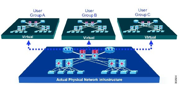
Deploying physical network infrastructure requires both capital investments for hardware, as well as manpower investments for installation and operational management support. When distinct user groups within an organization desire to control their own networks, it rarely makes economic sense for these user groups to deploy and manage separate physical networks. Physical plants are rarely utilized to their fullest, resulting in stranded capacity (bandwidth, processor, memory, etc.). In addition, the power, rack space, and cooling needs to physical plants do not satisfy modern “green” requirements. Network virtualization offers the opportunity to satisfy organizational needs, while efficiently utilizing physical assets.
The purpose of network virtualization, as shown in the figure below, is to create multiple, logically separated topologies across one common physical infrastructure.
When considering the deployment of a virtualized network environment, take into account both the device and the path level.
Device Level Virtualization
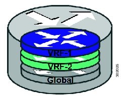
Virtualization at the device level entails the use of the virtual routing and forwarding (VRF) to create multiple instances of Layer 3 routing tables, as illustrated in the figure below. VRFs provide segmentation across IP addresses, allowing for overlapped address space and traffic separation. Separate routing, QoS, security, and management policies can be applied to each VRF instance. An IGP or EGP routing process is typically enabled within a VFR, just as it would be in the global (default) routing table. As described in detail below, LISP binds VRFs to instance IDs for similar purposes.
Path Level Virtualization
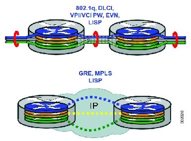
VRF table separation is maintained across network paths using any number of traditional mechanisms, as illustrated in the figure below. Single-hop path segmentation (hop-by-hop) is typically accomplished by techniques such as 802.1q VLANs, VPI/VCI PW, or EVN. LISP can also be used. Traditional multi-hop mechanisms include MPLS and GRE tunnels. As described in detail below, LISP binds VRFs to instance IDs (IIDs), and then these IIDs are included in the LISP header to provide data plane (traffic flow) separation for single or multihop needs.
LISP Virtualization at the Device Level
Recalling that LISP implements Locator ID separation and, in so doing, creates two namespaces (EIDs and RLOCs), it is easy to see that LISP virtualization can consider both EID and RLOC namespaces for virtualization. That is, either or both can be virtualized.
EID virtualization—Enabled by binding a LISP instance ID to an EID VRF. Instance IDs are numerical tags defined in the LISP canonical address format (LCAF) draft, and are used to maintain address space segmentation in both the control plane and data plane.
RLOC virtualization—Tying locator addresses and associated mapping services to the specific VRF within which they are reachable enables RLOC virtualization.
Because LISP considers virtualization of both EID and RLOC namespaces, two models of operation are defined: shared model and parallel model. For completeness, the discussions below begin first with a review of the default (non-virtualized) model of LISP, and then cover the details of shared and parallel models.
Default (Non-Virtualized) LISP Model
By default, LISP is not virtualized in either EID space or RLOC space. That is, unless otherwise configured, both EID and RLOC addresses are resolved in the default (global) routing table. This concept is illustrated in the figure below.
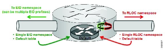
As shown in the figure above, both EID and RLOC addresses are resolved in the default table. The mapping system must also be reachable via the default table. This default model can be thought of as a single instantiation of the parallel model of LISP virtualization where EID and RLOC addresses are within the same namespace such as is the case in this default table.
LISP Shared Model Virtualization
LISP shared model virtualized EID space is created by binding VRFs associated with an EID space to Instance IDs. A common, shared locator space is used by all virtualized EIDs. This concept is illustrated in the figure below.
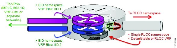
As shown in the figure above, EID space is virtualized through its association with VRFs, and these VRFs are tied to LISP Instance IDs to segment the control plane and data plane in LISP. A common, shared locator space, the default (global) table as shown in the figure above, is used to resolve RLOC addresses for all virtualized EIDs. The mapping system must also be reachable via the common locator space.
LISP Shared Model Virtualization Architecture
Architecturally, LISP shared model virtualization can be deployed in single or multitenancy configurations. In the shared model single tenancy case, xTRs are dedicated to a customer but share infrastructure with other customers. Each customer and all sites associated with it use the same instance ID and are part of a VPN using their own EID namespace as shown in the figure below.
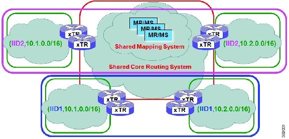
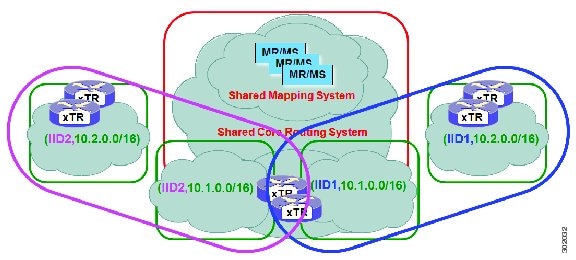
In the shared model multitenancy case, a set of xTRs is shared (virtualized) among multiple customers. These customers also share a common infrastructure with other single and multitenant customers. Each customer and all sites associated with it use the same instance ID and are part of a VPN using their own EID namespace as shown in the figure below.
LISP Shared Model Virtualization Implementation Considerations and Caveats
When LISP Shared Model is implemented, several important considerations and caveats are important. Instance IDs must be unique to an EID VRF. Review the example below:
xTR-1(config)# vrf definition alpha
xTR-1(config-vrf)# address-family ipv4
xTR-1(config-vrf-af)# exit
xTR-1(config)# vrf definition beta
xTR-1(config-vrf)# address-family ipv4
xTR-1(config-vrf-af)# exit
xTR-1(config-vrf)# exit
xTR-1(config)# router lisp
xTR-1(config-router-lisp)# eid-table vrf alpha instance-id 101
xTR-1(config-router-lisp-eid-table)# exit
xTR-1(config-router-lisp)# eid-table vrf beta instance-id 101
Instance ID 101 is bound to the vrf alpha EID table.
In the above example, two EID VRFs are created: alpha and beta. Under the router lisp command, an EID table VRF named alpha is specified and associated with the instance ID 101. Next, an EID table VRF named beta is specified and also associated with the instance ID 101. As indicated by the router, this is not permissible since instance ID 101 is already associated with the EID VRF named alpha. That is, you cannot connect the same instance-id to more than one EID VRF.
How to Configure LISP Shared Model Virtualization
- Configure Simple LISP Shared Model Virtualization
- Configure Large-Scale LISP Shared Model Virtualization
- Verifying and Troubleshooting LISP Virtualization
Configure Simple LISP Shared Model Virtualization
Perform this task to enable and configure LISP ITR/ETR (xTR) functionality with LISP map server and map resolver to implement LISP shared model virtualization. This LISP shared model reference configuration is for a very simple two-site LISP topology, including xTRs and an MS/MR.
The configuration implemented in this task and illustrated in the figure below shows a basic LISP shared model virtualization solution. In this example, two LISP sites are deployed, each containing two VRFs: PURPLE and GOLD. LISP is used to provide virtualized connectivity between these two sites across a common IPv4 core, while maintaining address separation between the two VRFs.
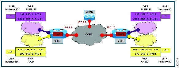
Each LISP Site uses a single edge router configured as both an ITR and ETR (xTR), with a single connection to its upstream provider. The RLOC is IPv4, and IPv4 and IPv6 EID prefixes are configured. Each LISP site registers to a map server/map resolver (MS/MR) device located in the network core within the shared RLOC address space. The topology used in this most basic LISP configuration is shown in the figure above.
The components illustrated in the topology shown in the figure above are described below:
-
LISP site: -
The CPE functions as a LISP ITR and ETR (xTR).
-
Both LISP xTRs have two VRFs: GOLD and PURPLE, with each VRF containing both IPv4 and IPv6 EID-prefixes, as shown in the figure above. Note the overlapping prefixes, used for illustration purposes. A LISP instance-id is used to maintain separation between two VRFs. Note that in this example, the share key is configured "per-site" and not "per-VRF." (Case 2 illustrates a configuration where the shared key is per-VPN.)
-
Each LISP xTR has a single RLOC connection to a shared IPv4 core network.
-
-
Mapping system: -
One map server/map resolver system is shown in the figure above and assumed available for the LISP xTR to register to. The MS/MR has an IPv4 RLOC address of 10.0.2.2, within the shared IPv4 core.
-
The map server site configurations are virtualized using LISP instance-ids to maintain separation between the two VRFs.
-
Perform the steps in this task (once through for each xTR in the LISP site) to enable and configure LISP ITR and ETR (xTR) functionality when using a LISP map-server and map-resolver for mapping services. The example configurations at the end of this task show the full configuration for two xTRs (xTR1 and xTR2).
The configuration below assumes that the referenced VRFs were created using the vrf definition command.
1.
configure
terminal
2.
router
lisp
3.
eid-table
vrfvrf-name
instance-id
instance-id
5. Repeat Step 4 until all EID-to-RLOC mappings for the LISP site are configured.
6.
exit
7.
ipv4
itr
8.
ipv4
etr
9.
ipv4
itr
map-resolver
map-resolver-address
10.
ipv4
etr
map-server
map-server-address
key
key-type
authentication-key
11.
ipv6
itr
12.
ipv6
etr
13.
ipv6
itr
map-resolver
map-resolver-address
14.
ipv6
etr
map-server
map-server-address
key
key-type
authentication-key
15.
exit
16.
ip
route
ipv4-prefix
next-hop
17.
exit
DETAILED STEPS
Example:
The examples below show the complete configuration for the LISP topology illustrated in the figure shown above the task steps and follows the examples in the steps in this task. On the xTRs, the VRFs and EID prefixes are assumed to be attached to VLANs configured on the devices.
Example configuration for the Left xTR:
hostname Left-xTR
!
ipv6 unicast-routing
!
vrf definition PURPLE
 address-family ipv4
 exit
 address-family ipv6
 exit
!
vrf definition GOLD
 address-family ipv4
 exit
 address-family ipv6
 exit
!
interface Ethernet0/0
 ip address 10.0.0.2 255.255.255.0
!
interface Ethernet1/0.1
 encapsulation dot1q 101
 vrf forwarding PURPLE
 ip address 192.168.1.1 255.255.255.0
 ipv6 address 2001:DB8:A:A::1/64
!
interface Ethernet1/0.2
 encapsulation dot1q 102
 vrf forwarding GOLD
 ip address 192.168.1.1 255.255.255.0
 ipv6 address 2001:DB8:B:A::1/64
!
router lisp
 eid-table vrf PURPLE instance-id 101
  database-mapping 192.168.1.0/24 10.0.0.2 priority 1 weight 1
  database-mapping 2001:DB8:A:A::/64 10.0.0.2 priority 1 weight 1
 eid-table vrf GOLD instance-id 102
  database-mapping 192.168.1.0/24 10.0.0.2 priority 1 weight 1
  database-mapping 2001:DB8:B:A::/64 10.0.0.2 priority 1 weight 1
 exit
 !
 ipv4 itr map-resolver 10.0.2.2
 ipv4 itr
 ipv4 etr map-server 10.0.2.2 key Left-key
 ipv4 etr
 ipv6 itr map-resolver 10.0.2.2
 ipv6 itr
 ipv6 etr map-server 10.0.2.2 key Left-key
 ipv6 etr
 exit
!
ip route 0.0.0.0 0.0.0.0 10.0.0.1
!
Example configuration for Right xTR:
hostname Right-xTR
!
ipv6 unicast-routing
!
vrf definition PURPLE
 address-family ipv4
 exit
 address-family ipv6
 exit
!
vrf definition GOLD
 address-family ipv4
 exit
 address-family ipv6
 exit
!
interface Ethernet0/0
 ip address 10.0.1.2 255.255.255.0
!
interface Ethernet1/0.1
 encapsulation dot1q 101
 vrf forwarding PURPLE
 ip address 192.168.2.1 255.255.255.0
 ipv6 address 2001:DB8:A:B::1/64
!
interface Ethernet1/0.2
 encapsulation dot1q 102
 vrf forwarding GOLD
 ip address 192.168.2.1 255.255.255.0
 ipv6 address 2001:DB8:B:B::1/64
!
router lisp
 eid-table vrf PURPLE instance-id 101
  database-mapping 192.168.2.0/24 10.0.1.2 priority 1 weight 1
  database-mapping 2001:DB8:A:B::/64 10.0.1.2 priority 1 weight 1
 eid-table vrf GOLD instance-id 102
  database-mapping 192.168.2.0/24 10.0.1.2 priority 1 weight 1
  database-mapping 2001:DB8:B:B::/64 10.0.1.2 priority 1 weight 1
 exit
 !
 ipv4 itr map-resolver 10.0.2.2
 ipv4 itr
 ipv4 etr map-server 10.0.2.2 key Right-key
 ipv4 etr
 ipv6 itr map-resolver 10.0.2.2
 ipv6 itr
 ipv6 etr map-server 10.0.2.2 key Right-key
 ipv6 etr
 exit
!
ip route 0.0.0.0 0.0.0.0 10.0.1.1
!
Configuring a Private LISP Mapping System for LISP Shared Model Virtualization
Perform this task to configure and enable standalone LISP map server/map resolver functionality for LISP shared model virtualization. In this task, a Cisco router is configured as a standalone map server/map resolver (MR/MS) for a private LISP mapping system. Because the MR/MS is configured as a stand-alone device, it has no need for LISP Alternate Logical Topology (ALT) connectivity. All relevant LISP sites must be configured to register with this map server so that this map server has full knowledge of all registered EID Prefixes within the (assumed) private LISP system.
1.
enable
2.
configure
terminal
3.
router lisp
4.
site
site-name
5.
authentication-key [key-type]
authentication-key
6.
eid-prefix
instance-id
instance-id
EID-prefix
7.
eid-prefix
instance-id
instance-id
EID-prefix
8.
exit
9.
ipv4
map-resolver
10.
ipv4
map-server
11.
ipv6
map-resolver
12.
ipv6
map-server
13.
end
DETAILED STEPS
| Command or Action | Purpose | |||
|---|---|---|---|---|
| Step 1 |
enable
Example: Router> enable |
Enables privileged EXEC mode. | ||
| Step 2 |
configure
terminal
Example: Router# configure terminal |
Enters global configuration mode. | ||
| Step 3 |
router lisp
Example: Router(config)# router lisp |
Enters LISP configuration mode (IOS only). | ||
| Step 4 |
site
site-name
Example: Router(config-router-lisp)# site Left |
Specifies a LISP site named Left and enters LISP site configuration mode.
| ||
| Step 5 |
authentication-key [key-type]
authentication-key
Example: Router(config-router-lisp-site)# authentication-key 0 Left-key |
Configures the password used to create the SHA-2 HMAC hash for authenticating the map register messages sent by an ETR when registering to the map server.
| ||
| Step 6 |
eid-prefix
instance-id
instance-id
EID-prefix
Example: Router(config-router-lisp-site)# eid-prefix instance-id 102 192.168.1.0/24 |
| ||
| Step 7 |
eid-prefix
instance-id
instance-id
EID-prefix
Example: Router(config-router-lisp-site)# eid-prefix instance-id 102 2001:db8:a:b::/64 |
| ||
| Step 8 |
exit
Example: Router(config-router-lisp-site)# exit |
Exits LISP site configuration mode and returns to LISP configuration mode. | ||
| Step 9 |
ipv4
map-resolver
Example: Router(config-router-lisp)# ipv4 map-resolver |
Enables LISP map resolver functionality for EIDs in the IPv4 address family. | ||
| Step 10 |
ipv4
map-server
Example: Router(config-router-lisp)# ipv4 map-server |
Enables LISP map server functionality for EIDs in the IPv4 address family. | ||
| Step 11 |
ipv6
map-resolver
Example: Router(config-router-lisp)# ipv6 map-resolver |
Enables LISP map resolver functionality for EIDs in the IPv6 address family. | ||
| Step 12 |
ipv6
map-server
Example: Router(config-router-lisp)# ipv6 map-server |
Enables LISP map server functionality for EIDs in the IPv6 address family. | ||
| Step 13 |
end
Example: Router(config-router-lisp)# end |
Exits LISP configuration mode and returns to privileged EXEC mode. |
Example:
Example configuration for the map server/map resolver.
hostname MSMR
!
interface Ethernet0/0
 ip address 10.0.2.2 255.255.255.0
!
 router lisp
  !
  site Left
   authentication-key Left-key
   eid-prefix instance-id 101 192.168.1.0/24
   eid-prefix instance-id 101 2001:DB8:A:A::/64
   eid-prefix instance-id 102 192.168.1.0/24
   eid-prefix instance-id 102 2001:DB8:B:A::/64
   exit
  !
  site Right
   authentication-key Right-key
   eid-prefix instance-id 101 192.168.2.0/24
   eid-prefix instance-id 101 2001:DB8:A:B::/64
   eid-prefix instance-id 102 192.168.2.0/24
   eid-prefix instance-id 102 2001:DB8:B:B::/64
   exit
  !
  ipv4 map-server
  ipv4 map-resolver
  ipv6 map-server
  ipv6 map-resolver
  exit
 !
 ip route 0.0.0.0 0.0.0.0 10.0.2.1
Configure Large-Scale LISP Shared Model Virtualization
Perform this task to enable and configure LISP ITR/ETR (xTR) functionality with LISP map server and map resolver to implement LISP shared model virtualization. This LISP shared model reference configuration is for a large-scale, multiple-site LISP topology, including xTRs and multiple MS/MRs.
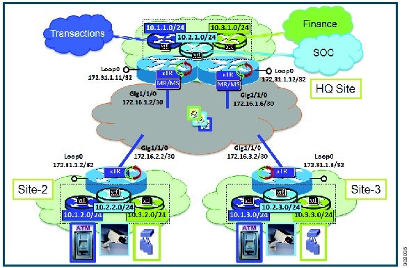
The configuration demonstrated in this task shows a more complex, larger scale LISP virtualization solution. In this task, an enterprise is deploying LISP Shared Model where EID space is virtualized over a shared, common core network. A subset of their entire network is illustrated in Figure 12. In this figure, three sites are shown: a multihomed "Headquarters" (HQ) site, and two remote office sites. The HQ site routers are deployed as xTRs and also as map resolver/map servers. The remote site routers only act as xTRs, and use the MS/MRs at the HQ site for LISP control plane support.
The components illustrated in the topology shown in the figure above are described below:
-
LISP site: -
Each CPE router functions as a LISP ITR and ETR (xTR), as well as a Map-Server/Map-Resolver (MS/MR).
-
Both LISP xTRs have three VRFs: TRANS (for transactions), SOC (for security operations), and FIN (for financials). Each VRF contains only IPv4 EID-prefixes. Note that no overlapping prefixes are used, but segmentation between each VRF by LISP instance-ids makes this possible. Also note that in this example, the separate authentication key is configured “per-vrf�? and not “per-site.�? This affects both the xTR and MS configurations.
-
The HQ LISP Site is multi-homed to the shared IPv4 core, but each xTR at the HQ site has a single RLOC.
-
Each CPE also functions as an MS/MR to which the HQ and Remote LISP sites can register.
-
The map server site configurations are virtualized using LISP instance IDs to maintain separation between the three VRFs.
-
The configuration below assumes that the referenced VRFs were created using the vrf definition command.
1.
configure
terminal
2.
router
lisp
3.
site
site-name
4.
authentication-key [key-type]
authentication-key
5.
eid-prefix
instance-id
instance-id
EID-prefix/prefix-length
accept-more-specifics
6.
exit
7. Repeat steps 3 through 6 for each LISP site to be configured.
8.
ipv4
map-resolver
9.
ipv4
map-server
10.
eid-table
vrfvrf-name
instance-id
instance-id
11.
database-mapping
EID-prefix/prefix-length
locator
priority
priority
weight
weight
12. Repeat Step 11 until all EID-to-RLOC mappings within this eid-table vrf and instance ID for the LISP site are configured.
13.
ipv4
etr
map-server
map-server-address
key
key-type
authentication-key
14. Repeat Step 13 to configure another locator address for the same LISP map server
15.
exit
16.
ipv4
itr
map-resolver
map-resolver-address
17. Repeat Step 16 to configure another locator address for the LISP map resolver
18.
ipv4
itr
19.
ipv4
etr
20.
exit
21.
ip
route
ipv4-prefix
next-hop
22.
exit
DETAILED STEPS
| Command or Action | Purpose | |||||
|---|---|---|---|---|---|---|
| Step 1 |
configure
terminal
Example: Router# configure terminal |
Enters global configuration mode. | ||||
| Step 2 |
router
lisp
Example: Router(config)# router lisp |
Enters LISP configuration mode ( software only). | ||||
| Step 3 |
site
site-name
Example: Router(config-router-lisp)# site TRANS |
Specifies a LISP site named TRANS and enters LISP site configuration mode.
| ||||
| Step 4 |
authentication-key [key-type]
authentication-key
Example: Router(config-router-lisp-site)# authentication-key 0 TRANS-key |
Configures the password used to create the SHA-2 HMAC hash for authenticating the map register messages sent by an ETR when registering to the map server.
| ||||
| Step 5 |
eid-prefix
instance-id
instance-id
EID-prefix/prefix-length
accept-more-specifics
Example: Router(config-router-lisp-site)# eid-prefix instance-id 1 10.1.0.0/16 accept-more-specifics |
| ||||
| Step 6 |
exit
Example: Router(config-router-lisp-site)# exit |
Exits LISP site configuration mode and returns to LISP configuration mode. | ||||
| Step 7 | Repeat steps 3 through 6 for each LISP site to be configured. |
In this example, steps 3 through 6 would be repeated for the site SOC and FIN as illustrated in the complete configuration example at the end of this task. | ||||
| Step 8 |
ipv4
map-resolver
Example: Router(config-router-lisp)# ipv4 map-resolver |
Enables LISP map resolver functionality for EIDs in the IPv4 address family. | ||||
| Step 9 |
ipv4
map-server
Example: Router(config-router-lisp)# ipv4 map-server |
Enables LISP map server functionality for EIDs in the IPv4 address family. | ||||
| Step 10 |
eid-table
vrfvrf-name
instance-id
instance-id
Example: Router(config-router-lisp)# eid-table vrf TRANS instance-id 1 |
Configures an association between a VRF table and a LISP instance ID, and enters eid-table configuration submode. | ||||
| Step 11 |
database-mapping
EID-prefix/prefix-length
locator
priority
priority
weight
weight
Example: Router(config-router-lisp-eid-table)# database-mapping 10.1.1.0/24 172.16.1.2 priority 1 weight 100 |
Configures an EID-to-RLOC mapping relationship and its associated traffic policy for this LISP site. | ||||
| Step 12 | Repeat Step
11 until all EID-to-RLOC mappings within this eid-table vrf and instance ID for
the LISP site are configured.
Example: Router(config-router-lisp-eid-table)# database-mapping 10.1.1.0/24 172.16.1.6 priority 1 weight 100 |
Configures an EID-to-RLOC mapping relationship and its associated traffic policy for this LISP site. | ||||
| Step 13 |
ipv4
etr
map-server
map-server-address
key
key-type
authentication-key
Example: Router(config-router-lisp-eid-table)# ipv4 etr map-server 172.16.1.2 key 0 TRANS-key |
Configures a locator address for the LISP map server and an authentication key for which this router, acting as an IPv4 LISP ETR, will use to register with the LISP mapping system.
| ||||
| Step 14 | Repeat Step 13
to configure another locator address for the same LISP map server
Example: Router(config-router-lisp-eid-table)# ipv4 etr map-server 172.16.1.6 key 0 TRANS-key |
Configures a locator address for the LISP map server and an authentication key for which this router, acting as an IPv4 LISP ETR, will use to register with the LISP mapping system. | ||||
| Step 15 |
exit
Example: Router(config-router-lisp-eid-table)# exit |
Exits eid-table configuration submode and returns to LISP configuration mode. | ||||
| Step 16 |
ipv4
itr
map-resolver
map-resolver-address
Example: Router(config-router-lisp)# ipv4 itr map-resolver 172.16.1.2 |
Configures a locator address for the LISP map resolver to which this router will send map request messages for IPv4 EID-to-RLOC mapping resolutions.
| ||||
| Step 17 | Repeat Step 16
to configure another locator address for the LISP map resolver
Example: Router(config-router-lisp)# ipv4 itr map-resolver 172.16.1.6 |
Configures a locator address for the LISP map resolver to which this router will send map request messages for IPv4 EID-to-RLOC mapping resolutions.
| ||||
| Step 18 |
ipv4
itr
Example: Router(config-router-lisp)# ipv4 itr |
Enables LISP ITR functionality for the IPv4 address family. | ||||
| Step 19 |
ipv4
etr
Example: Router(config-router-lisp)# ipv4 etr |
Enables LISP ETR functionality for the IPv4 address family. | ||||
| Step 20 |
exit
Example: Router(config-router-lisp)# exit |
Exits LISP configuration mode and returns to global configuration mode. | ||||
| Step 21 |
ip
route
ipv4-prefix
next-hop
Example: Router(config)# ip route 0.0.0.0 0.0.0.0 172.16.1.1 |
Configures a default route to the upstream next hop for all IPv4 destinations. | ||||
| Step 22 |
exit
Example: Router(config)# exit |
Exits global configuration mode. |
Example:
The examples below show the complete configuration for the HQ-RTR-1 and HQ-RTR-2 (xTR/MS/MR located at the HQ Site), and Site2-xTR LISP devices illustrated in the figure above and in this task. Note that both HQ-RTR-1 and HQ-RTR-2 are provided in order to illustrate the proper method for configuring a LISP multihomed site.
Example configuration for HQ-RTR-1 with an xTR, a map server and a map resolver:
hostname HQ-RTR-1
!
vrf definition TRANS
 address-family ipv4
 exit
!
vrf definition SOC
address-family ipv4
 exit
!
vrf definition FIN
address-family ipv4
 exit
!
interface Loopback0
 description Management Loopback (in default space)
 ip address 172.31.1.11 255.255.255.255
!
interface GigabitEthernet0/0/0
 description WAN Link to IPv4 Core
 ip address 172.16.1.2 255.255.255.252
 negotiation auto
!
interface GigabitEthernet0/0/1
 vrf forwarding TRANS
 ip address 10.1.1.1 255.255.255.0
 negotiation auto
!
interface GigabitEthernet0/0/2
 vrf forwarding SOC
 ip address 10.2.1.1 255.255.255.0
 negotiation auto
!
interface GigabitEthernet0/0/3
 vrf forwarding FIN
 ip address 10.3.1.1 255.255.255.0
 negotiation auto
!
router lisp
 eid-table default instance-id 0
  database-mapping 172.31.1.11/32 172.16.1.2 priority 1 weight 50
  database-mapping 172.31.1.11/32 172.16.1.6 priority 1 weight 50
  ipv4 etr map-server 172.16.1.2 key DEFAULT-key
  ipv4 etr map-server 172.16.1.6 key DEFAULT-key
  exit
 !
 eid-table vrf TRANS instance-id 1
  database-mapping 10.1.1.0/24 172.16.1.2 priority 1 weight 50
  database-mapping 10.1.1.0/24 172.16.1.6 priority 1 weight 50
  ipv4 etr map-server 172.16.1.2 key TRANS-key
  ipv4 etr map-server 172.16.1.6 key TRANS-key
  exit
 !
 eid-table vrf SOC instance-id 2
  database-mapping 10.2.1.0/24 172.16.1.2 priority 1 weight 50
  database-mapping 10.2.1.0/24 172.16.1.6 priority 1 weight 50
  ipv4 etr map-server 172.16.1.2 key SOC-key
  ipv4 etr map-server 172.16.1.6 key SOC-key
  exit
 !
 eid-table vrf FIN instance-id 3
  database-mapping 10.3.1.0/24 172.16.1.2 priority 1 weight 50
  database-mapping 10.3.1.0/24 172.16.1.6 priority 1 weight 50
  ipv4 etr map-server 172.16.1.2 key FIN-key
  ipv4 etr map-server 172.16.1.6 key FIN-key
  exit
 !
 site DEFAULT
  authentication-key DEFAULT-key
  eid-prefix 172.31.1.0/24 accept-more-specifics
  exit
 !
 site TRANS
  authentication-key TRANS-key
  eid-prefix instance-id 1 10.1.0.0/16 accept-more-specifics
  exit
 !
 site SOC
  authentication-key SOC-key
  eid-prefix instance-id 2 10.2.0.0/16 accept-more-specifics
  exit
 !
 site FIN
  authentication-key FIN-key
  eid-prefix instance-id 3 10.3.0.0/16 accept-more-specifics
  exit
 !
 ipv4 map-server
 ipv4 map-resolver
 ipv4 itr map-resolver 172.16.1.2
 ipv4 itr map-resolver 172.16.1.6
 ipv4 itr
 ipv4 etr
 exit
!
ip route 0.0.0.0 0.0.0.0 172.16.1.1
Example configuration for HQ-RTR-2 with an xTR, a map server and a map resolver:
hostname HQ-RTR-2
!
vrf definition TRANS
address-family ipv4
 exit
!
vrf definition SOC
address-family ipv4
 exit
!
vrf definition FIN
address-family ipv4
 exit
!
interface Loopback0
 description Management Loopback (in default space)
 ip address 172.31.1.12 255.255.255.255
!
interface GigabitEthernet0/0/0
 description WAN Link to IPv4 Core
 ip address 172.16.1.6 255.255.255.252
 negotiation auto
!
interface GigabitEthernet0/0/1
 vrf forwarding TRANS
 ip address 10.1.1.2 255.255.255.0
 negotiation auto
!
interface GigabitEthernet0/0/2
 vrf forwarding SOC
 ip address 10.2.1.2 255.255.255.0
 negotiation auto
!
interface GigabitEthernet0/0/3
 vrf forwarding FIN
 ip address 10.3.1.2 255.255.255.0
 negotiation auto
!
router lisp
 eid-table default instance-id 0
  database-mapping 172.31.1.12/32 172.16.1.2 priority 1 weight 50
  database-mapping 172.31.1.12/32 172.16.1.6 priority 1 weight 50
  ipv4 etr map-server 172.16.1.2 key DEFAULT-key
  ipv4 etr map-server 172.16.1.6 key DEFAULT-key
  exit
 !
 eid-table vrf TRANS instance-id 1
  database-mapping 10.1.1.0/24 172.16.1.2 priority 1 weight 50
  database-mapping 10.1.1.0/24 172.16.1.6 priority 1 weight 50
  ipv4 etr map-server 172.16.1.2 key TRANS-key
  ipv4 etr map-server 172.16.1.6 key TRANS-key
  exit
 !
 eid-table vrf SOC instance-id 2
  database-mapping 10.2.1.0/24 172.16.1.2 priority 1 weight 50
  database-mapping 10.2.1.0/24 172.16.1.6 priority 1 weight 50
  ipv4 etr map-server 172.16.1.2 key SOC-key
  ipv4 etr map-server 172.16.1.6 key SOC-key
  exit
 !
 eid-table vrf FIN instance-id 3
  database-mapping 10.3.1.0/24 172.16.1.2 priority 1 weight 50
  database-mapping 10.3.1.0/24 172.16.1.6 priority 1 weight 50
  ipv4 etr map-server 172.16.1.2 key FIN-key
  ipv4 etr map-server 172.16.1.6 key FIN-key
  exit
 !
 site DEFAULT
  authentication-key DEFAULT-key
  eid-prefix 172.31.1.0/24 accept-more-specifics
  exit
 !
 site TRANS
  authentication-key TRANS-key
  eid-prefix instance-id 1 10.1.0.0/16 accept-more-specifics
  exit
 !
 site SOC
  authentication-key SOC-key
  eid-prefix instance-id 2 10.2.0.0/16 accept-more-specifics
  exit
 !
 site FIN
  authentication-key FIN-key
  eid-prefix instance-id 3 10.3.0.0/16 accept-more-specifics
  exit
 !
 ipv4 map-server
 ipv4 map-resolver
 ipv4 itr map-resolver 172.16.1.2
 ipv4 itr map-resolver 172.16.1.6
 ipv4 itr
 ipv4 etr
 exit
!
ip route 0.0.0.0 0.0.0.0 172.16.1.5
Configure a Remote Site for Large-Scale LISP Shared Model Virtualization
Perform this task to enable and configure LISP ITR/ETR (xTR) functionality at a remote site to implement LISP shared model virtualization as part of a large-scale, multiple-site LISP topology.
The configuration demonstrated in this task is part of a more complex, larger scale LISP virtualization solution. In this task, the configuration applies to one of the remote sites shown in the figure below. In this task, the remote site routers only act as xTRs, and use the MS/MRs at the HQ site for LISP control plane support.
The components illustrated in the topology shown in the figure above are described below:
The configuration below assumes that the referenced VRFs were created using the vrf definition command and that the Configure a Large-Scale LISP Shared Model Virtualization task has been performed at one or more central (headquarters) sites.
1.
configure
terminal
2.
router
lisp
3.
eid-table
vrfvrf-name
instance-id
instance-id
4.
database-mapping
EID-prefix/prefix-length
locator
priority
priority
weight
weight
5.
ipv4
etr
map-server
map-server-address
key
key-type
authentication-key
6. Repeat Step 13 to configure another locator address for the same LISP map server
7.
exit
8.
ipv4
itr
map-resolver
map-resolver-address
9. Repeat Step 16 to configure another locator address for the LISP map resolver
10.
ipv4
itr
11.
ipv4
etr
12.
exit
13.
ip
route
ipv4-prefix
next-hop
14.
exit
DETAILED STEPS
| Command or Action | Purpose | |||||
|---|---|---|---|---|---|---|
| Step 1 |
configure
terminal
Example: Router# configure terminal |
Enters global configuration mode. | ||||
| Step 2 |
router
lisp
Example: Router(config)# router lisp |
Enters LISP configuration mode ( software only). | ||||
| Step 3 |
eid-table
vrfvrf-name
instance-id
instance-id
Example: Router(config-router-lisp)# eid-table vrf TRANS instance-id 1 |
Configures an association between a VRF table and a LISP instance ID, and enters eid-table configuration submode. | ||||
| Step 4 |
database-mapping
EID-prefix/prefix-length
locator
priority
priority
weight
weight
Example: Router(config-router-lisp-eid-table)# database-mapping 10.1.2.0/24 172.16.2.2 priority 1 weight 100 |
Configures an EID-to-RLOC mapping relationship and its associated traffic policy for this LISP site.
| ||||
| Step 5 |
ipv4
etr
map-server
map-server-address
key
key-type
authentication-key
Example: Router(config-router-lisp-eid-table)# ipv4 etr map-server 172.16.1.2 key 0 TRANS-key |
Configures a locator address for the LISP map server and an authentication key for which this router, acting as an IPv4 LISP ETR, will use to register with the LISP mapping system.
| ||||
| Step 6 | Repeat Step 13
to configure another locator address for the same LISP map server
Example: Router(config-router-lisp-eid-table)# ipv4 etr map-server 172.16.1.6 key 0 TRANS-key |
Configures a locator address for the LISP map server and an authentication key for which this router, acting as an IPv4 LISP ETR, will use to register with the LISP mapping system. | ||||
| Step 7 |
exit
Example: Router(config-router-lisp-eid-table)# exit |
Exits eid-table configuration submode and returns to LISP configuration mode. | ||||
| Step 8 |
ipv4
itr
map-resolver
map-resolver-address
Example: Router(config-router-lisp)# ipv4 itr map-resolver 172.16.1.2 |
Configures a locator address for the LISP map resolver to which this router will send map request messages for IPv4 EID-to-RLOC mapping resolutions.
| ||||
| Step 9 | Repeat Step 16
to configure another locator address for the LISP map resolver
Example: Router(config-router-lisp)# ipv4 itr map-resolver 172.16.1.6 |
Configures a locator address for the LISP map resolver to which this router will send map request messages for IPv4 EID-to-RLOC mapping resolutions.
| ||||
| Step 10 |
ipv4
itr
Example: Router(config-router-lisp)# ipv4 itr |
Enables LISP ITR functionality for the IPv4 address family. | ||||
| Step 11 |
ipv4
etr
Example: Router(config-router-lisp)# ipv4 etr |
Enables LISP ETR functionality for the IPv4 address family. | ||||
| Step 12 |
exit
Example: Router(config-router-lisp)# exit |
Exits LISP configuration mode and returns to global configuration mode. | ||||
| Step 13 |
ip
route
ipv4-prefix
next-hop
Example: Router(config)# ip route 0.0.0.0 0.0.0.0 172.16.2.1 |
Configures a default route to the upstream next hop for all IPv4 destinations. | ||||
| Step 14 |
exit
Example: Router(config)# exit |
Exits global configuration mode. |
Example:
The example below show the complete configuration for the remote site device illustrated in the figure above and in this task. Note that only one remote site configuration is shown here.
Example configuration for Site 2 with an xTR, and using the map server and a map resolver from the HQ site:
hostname Site2-xTR
!
vrf definition TRANS
address-family ipv4
 exit
!
vrf definition SOC
address-family ipv4
 exit
!
vrf definition FIN
address-family ipv4
 exit
!
interface Loopback0
 description Management Loopback (in default space)
 ip address 172.31.1.2 255.255.255.255
!
interface GigabitEthernet0/0/0
 description WAN Link to IPv4 Core
 ip address 172.16.2.2 255.255.255.252
 negotiation auto
!
interface GigabitEthernet0/0/1
 vrf forwarding TRANS
 ip address 10.1.2.1 255.255.255.0
 negotiation auto
!
interface GigabitEthernet0/0/2
 vrf forwarding SOC
 ip address 10.2.2.1 255.255.255.0
 negotiation auto
!
interface GigabitEthernet0/0/3
 vrf forwarding FIN
 ip address 10.3.2.1 255.255.255.0
 negotiation auto
!
router lisp
 eid-table default instance-id 0
  database-mapping 172.31.1.2/32 172.16.2.2 priority 1 weight 100
  ipv4 etr map-server 172.16.1.2 key DEFAULT-key
  ipv4 etr map-server 172.16.1.6 key DEFAULT-key
  exit
 !
 eid-table vrf TRANS instance-id 1
  database-mapping 10.1.2.0/24 172.16.2.2 priority 1 weight 100
  ipv4 etr map-server 172.16.1.2 key TRANS-key
  ipv4 etr map-server 172.16.1.6 key TRANS-key
  exit
 !
 eid-table vrf SOC instance-id 2
  database-mapping 10.2.2.0/24 172.16.2.2 priority 1 weight 100
  ipv4 etr map-server 172.16.1.2 key SOC-key
  ipv4 etr map-server 172.16.1.6 key SOC-key
  exit
 !
 eid-table vrf FIN instance-id 3
  database-mapping 10.3.2.0/24 172.16.2.2 priority 1 weight 100
  ipv4 etr map-server 172.16.1.2 key FIN-key
  ipv4 etr map-server 172.16.1.6 key FIN-key
  exit
 !
 ipv4 itr map-resolver 172.16.1.2
 ipv4 itr map-resolver 172.16.1.6
 ipv4 itr
 ipv4 etr
 exit
!
ip route 0.0.0.0 0.0.0.0 172.16.2.1
Verifying and Troubleshooting LISP Virtualization
After configuring LISP, verifying and troubleshooting LISP configuration and operations may be performed by following the optional steps described below. Note that certain verification and troubleshooting steps may only apply to certain types of LISP devices.
In this task, the topology is shown in the figure below and the configuration is from the “Configure Simple LISP Shared Model Virtualization” task, but the commands are applicable to both LISP shared and parallel model virtualization.
 Note | The following examples do not show every available command and every available output display. Refer to the Cisco IOS LISP Command Reference for detailed explanations of each command. |
1.
enable
2.
show running-config | section router lisp
3.
show [ip |
ipv6]
lisp
4.
show [ip |
ipv6]
lisp
map-cache
5.
show [ip |
ipv6]
lisp
database [eid-table
vrf
vrf-name]
6.
show
lisp
site [name
site-name]
7.
lig {[self {ipv4 |
ipv6}] | {hostname |
destination-EID}
8.
ping {hostname |
destination-EID}
9.
clear [ip |
ipv6]
lisp
map-cache
DETAILED STEPS
| Step 1 |
enable
Enables privileged EXEC mode. Enter your password if prompted. Example: Router> enable |
| Step 2 |
show running-config | section router lisp
The show running-config | section router lisp command is useful for quickly verifying the LISP configuration on the device. This command applies to any LISP device. The following is sample output from the show running-config | section router lisp command when a simple LISP site is configured with virtualized IPv4 and IPv6 EID prefixes and a shared IPv4 core: Example: Router# show running-config | section router lisp router lisp eid-table vrf PURPLE instance-id 101 database-mapping 192.168.1.0/24 10.0.0.2 priority 1 weight 1 database-mapping 2001:DB8:A:A::/64 10.0.0.2 priority 1 weight 1 eid-table vrf GOLD instance-id 102 database-mapping 192.168.1.0/24 10.0.0.2 priority 1 weight 1 database-mapping 2001:DB8:B:A::/64 10.0.0.2 priority 1 weight 1 exit ! ipv4 itr map-resolver 10.0.2.2 ipv4 itr ipv4 etr map-server 10.0.2.2 key Left-key ipv4 etr ipv6 itr map-resolver 10.0.2.2 ipv6 itr ipv6 etr map-server 10.0.2.2 key Left-key ipv6 etr exit |
| Step 3 |
show [ip |
ipv6]
lisp
The show ip lisp and show ipv6 lisp commands are useful for quickly verifying the operational status of LISP as configured on the device, as applicable to the IPv4 and IPv6 address families respectively. This command applies to any LISP device. Example: The first example shows a summary of LISP operational status and IPv6 address family information by EID table:
Router# show ipv6 lisp eid-table summary

Instance count: 2
Key: DB - Local EID Database entry count (@ - RLOC check pending
                                          * - RLOC consistency problem),
     DB no route - Local EID DB entries with no matching RIB route,
     Cache - Remote EID mapping cache size, IID - Instance ID,
     Role - Configured Role

                      Interface    DB  DB no  Cache Incom Cache
EID VRF name             (.IID)  size  route   size plete  Idle Role
PURPLE                LISP0.101     1      0      1  0.0%  0.0% ITR-ETR
GOLD                  LISP0.102     1      0      1  0.0%  0.0% ITR-ETR
Example: The second example shows LISP operational status and IPv6 address family information for the VRF named PURPLE: Router# show ipv6 lisp eid-table vrf PURPLE Instance ID: 101 Router-lisp ID: 0 Locator table: default EID table: PURPLE Ingress Tunnel Router (ITR): enabled Egress Tunnel Router (ETR): enabled Proxy-ITR Router (PITR): disabled Proxy-ETR Router (PETR): disabled Map Server (MS): disabled Map Resolver (MR): disabled Map-Request source: 2001:DB8:A:A::1 ITR Map-Resolver(s): 10.0.2.2 ETR Map-Server(s): 10.0.2.2 (00:00:24) ITR use proxy ETR RLOC(s): none Example: The third example shows LISP operational status and IPv6 address family information for the instance ID of 101:
Router# show ipv6 lisp instance-id 101

  Instance ID:                      101
  Ingress Tunnel Router (ITR):      enabled
  Egress Tunnel Router (ETR):       enabled
  Proxy-ITR Router (PITR):          disabled
  Proxy-ETR Router (PETR):          disabled
  Map Server (MS):                  disabled
  Map Resolver (MR):                disabled
  Map-Request source:               2001:DB8:A:A::1
  ITR Map-Resolver(s):              10.0.2.2
  ETR Map-Server(s):                10.0.2.2 (00:00:11)
  ITR Solicit Map Request (SMR):    accept and process
    Max SMRs per map-cache entry:   8 more specifics
    Multiple SMR suppression time:  60 secs
  ETR accept mapping data:          disabled, verify disabled
  ETR map-cache TTL:                1d00h
|
| Step 4 |
show [ip |
ipv6]
lisp
map-cache
The show ip lisp map-cache and show ipv6 lisp map-cache commands are useful for quickly verifying the operational status of the map cache on a device configured as an ITR or PITR, as applicable to the IPv4 and IPv6 address families respectively. Example: The following example shows IPv6 mapping cache information based on a configuration when a simple LISP site is configured with virtualized IPv4 and IPv6 EID prefixes and a shared IPv4 core. This example output assumes that a map-cache entry has been received for another site with the IPv6 EID prefix 2001:db8:b:b::/64. Router# show ip lisp map-cache eid-table vrf GOLD LISP IPv6 Mapping Cache for EID-table vrf GOLD (IID 102), 2 entries ::/0, uptime: 01:09:52, expires: never, via static send map-request Negative cache entry, action: send-map-request 2001:DB8:B:B::/64, uptime: 00:00:10, expires: 23:59:42, via map-reply, complete Locator Uptime State Pri/Wgt 10.0.1.2 00:00:10 up 1/1 |
| Step 5 |
show [ip |
ipv6]
lisp
database [eid-table
vrf
vrf-name]
The show ip lisp database and show ipv6 lisp database commands are useful for quickly verifying the operational status of the database mapping on a device configured as an ETR, as applicable to the IPv4 and IPv6 address families respectively. Example: The following example shows IPv6 mapping database information for the VRF named GOLD. Router# show ipv6 lisp database eid-table vrf GOLD LISP ETR IPv6 Mapping Database for EID-table vrf GOLD (IID 102), LSBs: 0x1, 1 entries EID-prefix: 2001:DB8:B:A::/64 10.0.0.2, priority: 1, weight: 1, state: site-self, reachable |
| Step 6 |
show
lisp
site [name
site-name]
The show lisp site command is useful for quickly verifying the operational status of LISP sites, as configured on a map server. This command only applies to a device configured as a map server. The following example output is based on a configuration when a simple LISP site is configured with virtualized IPv4 and IPv6 EID prefixes and shows the information for the instance ID of 101. Example:
Router# show lisp site instance-id 101

LISP Site Registration Information

Site Name      Last      Up   Who Last             Inst     EID Prefix
               Register       Registered           ID
Left           00:00:36  yes  10.0.0.2             101      192.168.1.0/24
               00:00:43  yes  10.0.0.2             101      2001:DB8:A:A::/64
Right          00:00:31  yes  10.0.1.2             101      192.168.2.0/24
               00:00:02  yes  10.0.1.2             101      2001:DB8:A:B::/64
Example: This second example shows LISP site information for the IPv6 EID prefix of 2001:db8:a:a:/64 and instance ID of 101.
Router# show lisp site 2001:db8:a:a:/64 instance-id 101

LISP Site Registration Information

Site name: Left
Allowed configured locators: any
Requested EID-prefix:
  EID-prefix: 2001:DB8:A:A::/64 instance-id 101
    First registered:     02:41:55
    Routing table tag:    0
    Origin:               Configuration
    Registration errors:
      Authentication failures:   4
      Allowed locators mismatch: 0
    ETR 10.0.0.2, last registered 00:00:22, no proxy-reply, no map-notify
                  TTL 1d00h
      Locator   Local  State      Pri/Wgt
      10.0.0.2  yes    up           1/1
|
| Step 7 |
lig {[self {ipv4 |
ipv6}] | {hostname |
destination-EID}
The LISP Internet Groper (lig) command is useful for testing the LISP control plane. The lig command can be used to query for the indicated destination hostname or EID, or the routers local EID-prefix. This command provides a simple means of testing whether a destination EID exists in the LISP mapping database system, or your site is registered with the mapping database system. This command is applicable for both the IPv4 and IPv6 address families and applies to any LISP device that maintains a map cache (for example, if configured as an ITR or PITR). The following example output is based on a configuration when a simple LISP site is configured with virtualized IPv4 and IPv6 EID prefixes and shows the information for the instance ID of 101 and the IPv4 EID prefix of 192.168.2.1. Example: Router# lig instance-id 101 192.168.2.1 Mapping information for EID 192.168.2.1 from 10.0.1.2 with RTT 12 msecs 192.168.2.0/24, uptime: 00:00:00, expires: 23:59:52, via map-reply, complete Locator Uptime State Pri/Wgt 10.0.1.2 00:00:00 up 1/1 Example: This second example output shows information about the VRF named PURPLE: Router# lig eid-table vrf PURPLE self Mapping information for EID 192.168.1.0 from 10.0.0.1 with RTT 20 msecs 192.168.1.0/24, uptime: 00:00:00, expires: 23:59:52, via map-reply, self Locator Uptime State Pri/Wgt 10.0.0.1 00:00:00 up, self 1/1 |
| Step 8 |
ping {hostname |
destination-EID}
The following example output from the ping command is based on a configuration when a simple LISP site is configured with virtualized IPv4 and IPv6 EID prefixes. (Note that ping is not a LISP command and does not know about an EID table or an instance ID. When virtualization is included, output limiters can only be specified by VRF.) Example: Router# ping vrf PURPLE 2001:DB8:a:b::1 source 2001:DB8:a:a::1 rep 100 Type escape sequence to abort. Sending 100, 100-byte ICMP Echos to 2001:DB8:A:B::1, timeout is 2 seconds: Packet sent with a source address of 2001:DB8:A:A::1%PURPLE !!!!!!!!!!!!!!!!!!!!!!!!!!!!!!!!!!!!!!!!!!!!!!!!!!!!!!!!!!!!!!!!!!!!!! Success rate is 100 percent (100/100), round-trip min/avg/max = 0/0/1 ms Example: Router# ping vrf GOLD Protocol [ip]: ipv6 Target IPv6 address: 2001:db8:b:b::1 Repeat count [5]: Datagram size [100]: Timeout in seconds [2]: Extended commands? [no]: y Source address or interface: 2001:db8:b:a::1 . . . Type escape sequence to abort. Sending 5, 100-byte ICMP Echos to 2001:DB8:B:B::1, timeout is 2 seconds: Packet sent with a source address of 2001:DB8:B:A::1%GOLD !!!!! Success rate is 100 percent (5/5), round-trip min/avg/max = 0/0/0 ms |
| Step 9 |
clear [ip |
ipv6]
lisp
map-cache
The clear ip lisp map-cache and clear ipv6 lisp map-cache commands remove all IPv4 or IPv6 dynamic LISP map-cache entries stored by the router. This can be useful trying to quickly verify the operational status of the LISP control plane. This command applies to a LISP device that maintains a map cache (for example, if configured as an ITR or PITR). Example: The following example displays IPv4 mapping cache information for instance ID 101, shows the command used to clear the mapping cache for instance ID 101, and displays the show information after clearing the cache. Router# show ip lisp map-cache instance-id 101 LISP IPv4 Mapping Cache for EID-table vrf PURPLE (IID 101), 2 entries 0.0.0.0/0, uptime: 00:25:17, expires: never, via static send map-request Negative cache entry, action: send-map-request 192.168.2.0/24, uptime: 00:20:13, expires: 23:39:39, via map-reply, complete Locator Uptime State Pri/Wgt 10.0.1.2 00:20:13 up 1/1 Router# clear ip lisp map-cache instance-id 101 Router# show ip lisp map-cache instance-id 101 LISP IPv4 Mapping Cache, 1 entries 0.0.0.0/0, uptime: 00:00:02, expires: never, via static send map-request Negative cache entry, action: send-map-request |
Configuration Examples for LISP Shared Model Virtualization
Complete configuration examples are available within each task under the “How to Configure LISP Shared Model Virtualization” section.
Additional References
Related Documents
|
Document Title |
Location |
|---|---|
|
Cisco IOS IP Routing: LISP Command Reference |
http://www.cisco.com/en/US/docs/ios-xml/ios/iproute_lisp/command/ip-lisp-cr-book.html |
|
Enterprise IPv6 Transitions Strategy Using the Locator/ID Separation Protocol |
|
|
Cisco IOS LISP0 Virtual Interface, Application Note, Version 1.0 |
|
|
Cross-Platform Release Notes for Cisco IOS Release 15.2M&T |
http://www.cisco.com/en/US/docs/ios/15_2m_and_t/release/notes/15_2m_and_t.html |
Standards
|
Standard |
Title |
|---|---|
|
IANA Address Family Numbers |
http://www.iana.org/assignments/address-family-numbers/address-family-numbers.xml |
MIBs
|
MIB |
MIBs Link |
|---|---|
|
None |
To locate and download MIBs for selected platforms, Cisco IOS software releases, and feature sets, use Cisco MIB Locator found at the following URL: http://www.cisco.com/go/mibs |
RFCs
|
RFC |
Title |
|---|---|
|
draft-ietf-lisp-22 |
Locator/ID Separation Protocol (LISP) http://tools.ietf.org/html/draft-ietf-lisp-22 |
|
draft-ietf-lisp-ms-16 |
LISP Map Server http://tools.ietf.org/html/draft-ietf-lisp-ms-16 |
|
draft-ietf-lisp-alt-10 |
LISP Alternative Topology (LISP+ALT) http://tools.ietf.org/html/draft-ietf-lisp-alt-10 |
|
draft-ietf-lisp-LCAF-06 |
LISP Canonical Address Format (LCAF) http://tools.ietf.org/wg/lisp/ |
|
draft-ietf-lisp-interworking-06 |
Interworking LISP with IPv4 and IPv6 http://tools.ietf.org/html/draft-ietf-lisp-interworking-06 |
|
draft-ietf-lisp-lig-06 |
LISP Internet Groper (LIG) http://tools.ietf.org/html/draft-ietf-lisp-lig-06 |
|
draft-ietf-lisp-mib-03 |
LISP MIB http://tools.ietf.org/wg/lisp/draft-ietf-lisp-mib/ |
Technical Assistance
|
Description |
Link |
|---|---|
|
The Cisco Support and Documentation website provides online resources to download documentation, software, and tools. Use these resources to install and configure the software and to troubleshoot and resolve technical issues with Cisco products and technologies. Access to most tools on the Cisco Support and Documentation website requires a Cisco.com user ID and password. |
Feature Information for LISP Shared Model Virtualization
The following table provides release information about the feature or features described in this module. This table lists only the software release that introduced support for a given feature in a given software release train. Unless noted otherwise, subsequent releases of that software release train also support that feature.
Use Cisco Feature Navigator to find information about platform support and Cisco software image support. To access Cisco Feature Navigator, go to www.cisco.com/go/cfn. An account on Cisco.com is not required.Feature Name |
Releases |
Feature Information |
|---|---|---|
|
LISP Shared Model Virtualization |
15.2(2)T 15.1(1)SY1 |
LISP Shared Model Virtualization feature uses Endpoint Identifier (EID) spaces that are created by binding VRFs associated with an EID space to Instance IDs. A common, “shared” locator space is used by all virtualized EIDs. |
 Feedback