- Locator ID Separation Protocol (LISP) Overview
- Configuring LISP (Locator ID Separation Protocol)
- LISP Multicast
- LISP Shared Model Virtualization
- LISP Parallel Model Virtualization
- LISP Host Mobility Across Subnet
- LISP Delegate Database Tree (DDT)
- LISP ESM Multihop Mobility
- LISP Support for Disjoint RLOC Domains
- Redistribution of RIB Routes into LISP
- Export Map Server Site Database in Map Server
- LISP Data Plane Security
- LISP Reliable Registration
- Overlapping Prefix
- LISP Generalized SMR
- TTL Propagate Disable and Site-ID Qualification
- Prerequsites for Configuring LISP
- How to Configure LISP
- Configure a Dual-Homed LISP Site with Two IPv4 RLOCs and an IPv4 EID
- Configure a Multihomed LISP Site with Two xTRs and Two IPv4 RLOCs and an IPv4 EID
- Configure a Multihomed LISP Site with Two xTRs and Two IPv4 RLOCs and Both an IPv4 and an IPv6 EID
- Configure a Multihomed LISP Site with Two xTRs that Each have Both an IPv4 and an IPv6 RLOC and Both an IPv4 and an IPv6 EID
- Configure a Private LISP Mapping System Using a Standalone Map Resolver/Map Server
- Configure a Public Mapping System Using Separate ALT-Connected Map Resolver and Map Server Devices
- Configure a PETR and a PITR
- Verify and Troubleshoot Locator ID Separation Protocol
- Additional References
- Feature Information for LISP
Configuring LISP (Locator ID
Separation Protocol)
This guide describes how to configure basic Locator ID Separation Protocol (LISP) functionality on all LISP-related devices, including the egress tunnel router (ETR), ingress tunnel router (ITR), proxy ETR (PETR), proxy ITR (PITR), map resolver (MR), map server (MS), and LISP-ALT device.
LISP is a network architecture and protocol that implements the use of two namespaces instead of a single IP address. These namespaces, known as endpoint identifiers (EIDs), are assigned to end-hosts and routing locators (RLOCs), which are assigned to devices (primarily routers) that make up the global routing system. Splitting EID and RLOC functions delivers improvements in routing system scalability, multi-homing efficiency, and ingress traffic engineering.
- Prerequsites for Configuring LISP
- How to Configure LISP
- Additional References
- Feature Information for LISP
Prerequsites for Configuring LISP
-
If a LISP xTR is also a First Hop Router (FH) or a Rendezvous Point (RP), then the xTR needs to have at least one connected interface that is covered by a local LISP database mapping. Before an ITR forwards traffic over LISP, it does a source check to ensure that the source address of the traffic stream is a local EID (database mapping). Since PIM register and register-stop messages are sourced directly from the router itself, to be forwarded over LISP, the messages must come from an interface covered by a database mapping. A loopback or other connected interface is fine for this purpose. No additional configuration is required to ensure the proper address is selected.
This prerequisite is not required on a Proxy xTR, which does not do a source check.
How to Configure LISP
- Configure a Dual-Homed LISP Site with Two IPv4 RLOCs and an IPv4 EID
- Configure a Multihomed LISP Site with Two xTRs and Two IPv4 RLOCs and an IPv4 EID
- Configure a Multihomed LISP Site with Two xTRs and Two IPv4 RLOCs and Both an IPv4 and an IPv6 EID
- Configure a Multihomed LISP Site with Two xTRs that Each have Both an IPv4 and an IPv6 RLOC and Both an IPv4 and an IPv6 EID
- Configure a Private LISP Mapping System Using a Standalone Map Resolver/Map Server
- Configure a Public Mapping System Using Separate ALT-Connected Map Resolver and Map Server Devices
- Configure a PETR and a PITR
- Verify and Troubleshoot Locator ID Separation Protocol
Configure a Dual-Homed LISP Site with Two IPv4 RLOCs and an IPv4 EID
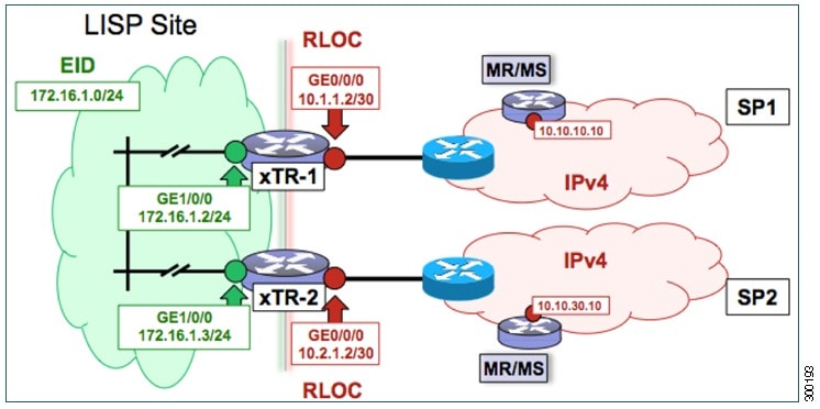
Perform this task to configure a dual-homed LISP site with two IPv4 RLOCs and an IPv4 EID. In this task, a LISP site uses a single edge router configured as both an ITR and an ETR (known as an xTR) with two connections to upstream providers. Both of the RLOCs and the EID prefix are IPv4. The LISP site registers to two map resolver/map server (MR/MS) devices in the network core. The topology used in this LISP configuration is shown in the figure below.

The components illustrated in the topology shown in the figure are described below:
-
LISP site: - The CPE functions as a LISP ITR and ETR (xTR).
- The LISP xTR is authoritative for the IPv4 EID prefix of 172.16.1.0/24.
- The LISP xTR has two RLOC connections to the core. The RLOC connection to SP1 is 10.1.1.2/30; the RLOC connection to SP2 is 10.2.1.2/30.
- For this simple dual-homed configuration, the LISP site policy specifies equal load sharing between service provider (SP) links for ingress traffic engineering.
-
Mapping system: -
Two map resolver/map server (MR/MS) systems are assumed to be available for the LISP xTR to configure. The MR/MSs have IPv4 RLOCs 10.10.10.10 and 10.10.30.10.
-
Mapping Services are assumed to be provided as part of this LISP solution via a private mapping system or as a public LISP mapping system. From the perspective of the configuration of this LISP site xTR, there is no difference. 
Note
Map server and map resolver configurations are not shown here. See the "Configure a Private LISP Mapping System Using a Standalone Map Resolver/Map Server" section for information about map server and map resolver configuration.
-
This task shows how to enable and configure LISP ITR and ETR (xTR) functionality when using a LISP map server and map resolver for mapping services.
1.
configure
terminal
2.
router
lisp
4. Repeat one of the choices in Step 3 to configure a second RLOC.
5.
ipv4
itr
6.
ipv4
etr
7.
ipv4
itr
map-resolver
map-resolver-address
8.
ipv4
etr
map-server
map-server-address
key
key-type
authentication-key
9.
exit
10.
ip
route
ipv4-prefix
next-hop
11.
exit
DETAILED STEPS
Example:
This example shows the complete configuration for the LISP topology illustrated in the figure above and in this task.
hostname xTR
!
no ip domain lookup
ip cef
!
interface Loopback0
 ip address 172.17.1.1 255.255.255.255
!
interface LISP0
!
interface GigabitEthernet0/0/0
 description Link to SP1 (RLOC)
 ip address 10.1.1.2 255.255.255.252
!
interface GigabitEthernet0/0/1
 description Link to SP2 (RLOC)
 ip address 10.2.1.2 255.255.255.252
!
interface GigabitEthernet1/0/0
 description Link to Site (EID)
 ip address 172.16.1.1 255.255.255.0
!
router lisp
 database-mapping 172.16.1.0/24 10.1.1.2 priority 1 weight 50
 database-mapping 172.16.1.0/24 10.2.1.2 priority 1 weight 50
 ipv4 itr
 ipv4 etr
 ipv4 itr map-resolver 10.10.10.10
 ipv4 itr map-resolver 10.10.30.10
 ipv4 etr map-server 10.10.10.10 key 0 some-key
 ipv4 etr map-server 10.10.30.10 key 0 some-key
 exit
!
ip route 0.0.0.0 0.0.0.0 10.1.1.1
ip route 0.0.0.0 0.0.0.0 10.2.1.1
Configure a Multihomed LISP Site with Two xTRs and Two IPv4 RLOCs and an IPv4 EID
Perform this task to configure a multihomed LISP site with two xTRs, two IPv4 RLOCs, and an IPv4 EID. In this task, a LISP site uses two edge routers. Each edge router is configured as an xTR (each performs as both an ITR and an ETR) and each also includes a single IPv4 connection to an upstream provider. (Two different providers are used in this example but the same upstream provider could be used for both connections.) Both of the RLOCs and the EID prefix are IPv4. The LISP site registers to two map resolver/map server (MR/MS) devices in the network core. The topology used in this typical multihomed LISP configuration is shown in the figure below.
The components illustrated in the topology shown in the figure are described below:
-
LISP site: - Two CPE routers make up the LISP site: xTR-1 and xTR-2.
- Both CPE routers function as LISP xTRs (that is, an ITR and an ETR).
- The LISP site is authoritative for the IPv4 EID prefix of 172.16.1.0/24.
- Each LISP xTR has a single IPv4 RLOC connection to the core: the RLOC connection for xTR-1 to SP1 is 10.1.1.2/30; the RLOC connection for xTR-2 to SP2 is 10.2.1.2/30.
- For this multihomed case, the LISP site policy specifies equal load-sharing between service provider (SP) links for ingress traffic engineering.
-
Mapping system: -
Two map resolver/map server (MR/MS) systems are assumed to be available for the LISP xTR to configure. The MR/MSs have IPv4 RLOCs 10.10.10.10 and 10.10.30.10.
-
Mapping services are assumed to be provided as part of this LISP solution via a private mapping system or as a public LISP mapping system. From the perspective of the configuration of these LISP site xTRs, there is no difference.
Note
Map server and map resolver configurations are not shown here. See the "Configure a Private LISP Mapping System Using a Standalone Map Resolver/Map Server" section for information about map server and map resolver configuration.
-
Perform the steps in this task (once through for each xTR in the LISP site) to enable and configure LISP ITR and ETR (xTR) functionality when using a LISP map server and map resolver for mapping services. The example configurations at the end of this task show the full configuration for configuring two xTRs (xTR1 and xTR2).
1.
configure
terminal
2.
router
lisp
3.
database-mapping
EID-prefix/prefix-length
locator
priority
priority
weight
weight
4. Repeat Step 3 to configure a second RLOC for the same xTR.
5.
ipv4
itr
6.
ipv4
etr
7.
ipv4
itr
map-resolver
map-resolver-address
8. Repeat Step 7 to configure a second locator address for the map resolver.
9.
ipv4
etr
map-server
map-server-address
key
key-type
authentication-key
10. Repeat Step 9 to configure a second locator address for the map server.
11.
exit
12.
ip
route
ipv4-prefix
next-hop
13.
exit
DETAILED STEPS
| Command or Action | Purpose | |||||
|---|---|---|---|---|---|---|
| Step 1 |
configure
terminal
Example: Router# configure terminal |
Enters global configuration mode. | ||||
| Step 2 |
router
lisp
Example: Router(config)# router lisp |
Enters LISP configuration mode ( software only). | ||||
| Step 3 |
database-mapping
EID-prefix/prefix-length
locator
priority
priority
weight
weight
Example: Router(config-router-lisp)# database-mapping 172.16.1.0/24 10.1.1.2 priority 1 weight 50 |
Configures an EID-to-RLOC mapping relationship and its associated traffic policy for this LISP site.
| ||||
| Step 4 | Repeat Step 3
to configure a second RLOC for the same xTR.
Example: Router(config-router-lisp)# database-mapping 172.16.1.0/24 10.2.1.2 priority 1 weight 50 |
Configures an EID-to-RLOC mapping relationship and its associated traffic policy for an xTR on this LISP site.
| ||||
| Step 5 |
ipv4
itr
Example: Router(config-router-lisp)# ipv4 itr |
Enables LISP ITR functionality for the IPv4 address family. | ||||
| Step 6 |
ipv4
etr
Example: Router(config-router-lisp)# ipv4 etr |
Enables LISP ETR functionality for the IPv4 address family. | ||||
| Step 7 |
ipv4
itr
map-resolver
map-resolver-address
Example: Router(config-router-lisp)# ipv4 itr map-resolver 10.10.10.10 |
Configures a locator address for the LISP map resolver to which this router will send Map-Request messages for IPv4 EID-to-RLOC mapping resolutions.
| ||||
| Step 8 | Repeat Step 7
to configure a second locator address for the map resolver.
Example: Router(config-router-lisp)# ipv4 itr map-resolver 10.10.30.10 |
Configures a second locator address for the LISP map resolver to which this router will send Map-Request messages for IPv4 EID-to-RLOC mapping resolutions. | ||||
| Step 9 |
ipv4
etr
map-server
map-server-address
key
key-type
authentication-key
Example: Router(config-router-lisp)# ipv4 etr map-server 10.10.10.10 key 0 some-key |
Configures a locator address for the LISP map server and an authentication key that this router, acting as an IPv4 LISP ETR, will use to register with the LISP mapping system.
| ||||
| Step 10 | Repeat Step 9
to configure a second locator address for the map server.
Example: Router(config-router-lisp)# ipv4 etr map-server 10.10.30.10 key 0 some-key |
Configures a second locator address for the LISP map server and the authentication key that this router will use to register with the LISP mapping system. | ||||
| Step 11 |
exit
Example: Router(config-router-lisp)# exit |
Exits LISP configuration mode and returns to global configuration mode. | ||||
| Step 12 |
ip
route
ipv4-prefix
next-hop
Example: Router(config)# ip route 0.0.0.0 0.0.0.0 10.1.1.1 |
Configures a default route to the upstream next hop for all IPv4 destinations. | ||||
| Step 13 |
exit
Example: Router(config)# exit |
Exits global configuration mode. |
Example:
The examples below show the complete configuration for the LISP topology illustrated in the figure above and in this task:
Example configuration for xTR-1:
!
hostname xTR-1
!
no ip domain lookup
ip cef
!
interface Loopback0
 ip address 172.17.1.1 255.255.255.255
!
interface LISP0
!
interface GigabitEthernet0/0/0
 description Link to SP1 (RLOC)
 ip address 10.1.1.2 255.255.255.252
!
interface GigabitEthernet1/0/0
 description Link to Site (EID)
 ip address 172.16.1.2 255.255.255.0
!
router lisp
 database-mapping 172.16.1.0/24 10.1.1.2 priority 1 weight 50
 database-mapping 172.16.1.0/24 10.2.1.2 priority 1 weight 50
 ipv4 itr
 ipv4 etr
 ipv4 itr map-resolver 10.10.10.10
 ipv4 itr map-resolver 10.10.30.10
 ipv4 etr map-server 10.10.10.10 key 0 some-key
 ipv4 etr map-server 10.10.30.10 key 0 some-key
 exit
!
ip route 0.0.0.0 0.0.0.0 10.1.1.1
Example configuration for xTR-2:
!
hostname xTR-2
!
no ip domain lookup
ip cef
!
interface Loopback0
 ip address 172.17.1.2 255.255.255.255
!
interface LISP0
!
interface GigabitEthernet0/0/0
 description Link to SP2 (RLOC)
 ip address 10.2.1.2 255.255.255.252
!
interface GigabitEthernet1/0/0
 description Link to Site (EID)
 ip address 172.16.1.3 255.255.255.0
!
router lisp
 database-mapping 172.16.1.0/24 10.1.1.2 priority 1 weight 50
 database-mapping 172.16.1.0/24 10.2.1.2 priority 1 weight 50
 ipv4 itr
 ipv4 etr
 ipv4 itr map-resolver 10.10.10.10
 ipv4 itr map-resolver 10.10.30.10
 ipv4 etr map-server 10.10.10.10 key 0 some-key
 ipv4 etr map-server 10.10.30.10 key 0 some-key
 exit
!
ip route 0.0.0.0 0.0.0.0 10.2.1.1
Configure a Multihomed LISP Site with Two xTRs and Two IPv4 RLOCs and Both an IPv4 and an IPv6 EID
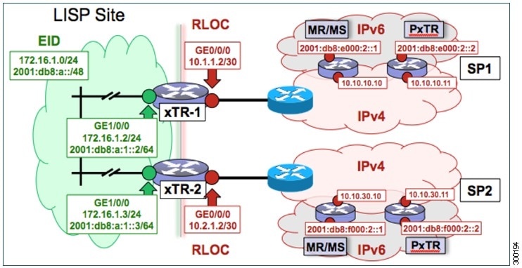
Perform this task to configure a multihomed LISP site with two xTRs, two IPv4 RLOCs, and both an IPv4 and an IPv6 EID. In this task, a LISP site uses two edge routers. Each edge router is configured as an xTR (each performs as both an ITR and an ETR) and each also includes a single IPv4 connection to an upstream provider. (Two different providers are used in this example but the same upstream provider could be used for both connections.) Both of the RLOCs and one of the EIDs are IPv4. However, in this example, the LISP site includes an IPv6 EID, as well.
This LISP site requires the use of Proxy Ingress/Egress Tunnel Router (PxTR) LISP infrastructure for access to non-LISP IPv6 addresses. That is, the LISP site uses only its IPv4 RLOCs to reach IPv6 LISP and non-LISP addresses. Additionally, this LISP site registers to two map resolver/map server (MR/MS) devices in the network core. The topology used in this multihomed LISP configuration is shown in the figure below.
The components illustrated in the topology shown in the figure are described below:
-
LISP site: - Two CPE routers make up the LISP site: xTR-1 and xTR-2.
- Both CPE routers function as LISP xTRs (that is, an ITR and an ETR).
- The LISP site is authoritative for both the IPv4 EID prefix of 172.16.1.0/24 and the IPv6 EID prefix 2001:db8:a::/48.
- Each LISP xTR has a single RLOC connection to the core: the RLOC connection for xTR-1 to SP1 is 10.1.1.2/30; the RLOC connection for xTR-2 to SP2 is 10.2.1.2/30.
- For this multihomed case, the LISP site policy specifies equal load-sharing between service provider (SP) links for ingress traffic engineering.
-
Mapping system: -
Two map resolver/map server (MR/MS) systems are assumed to be available for the LISP xTR to configure. The MR/MSs have IPv4 RLOCs 10.10.10.10 and 10.10.30.10.
-
Mapping services are assumed to be provided as part of this LISP solution via a private mapping system or as a public LISP mapping system. From the perspective of the configuration of these LISP site xTRs, there is no difference.
Note
Map server and map resolver configurations are not shown here. See the "Configure a Private LISP Mapping System Using a Standalone Map Resolver/Map Server" section for information about map server and map resolver configuration.
- PxTR services are also assumed to be provided as part of this LISP solution via a private or public mapping system. From the perspective of the configuration of these LISP site xTRs, there is no difference.
- The PxTRs have IPv4 RLOCs of 10.10.10.11 and 10.10.30.11 and will be used (as PETRs) for LISP IPv6 EIDs to reach non-LISP IPv6 sites. Return traffic is attracted by the PITR function (with the assumption that the PITR advertises coarse aggregates for IPv6 LISP EIDs into the IPv6 core.)
-
Perform the steps in this task (once through for each xTR in the LISP site) to enable and configure LISP ITR and ETR (xTR) functionality when using a LISP map server and map resolver for mapping services. The example configurations at the end of this task show the full configuration for two xTRs (xTR1 and xTR2).
1.
configure
terminal
2.
router
lisp
3.
database-mapping
EID-prefix/prefix-length
locator
priority
priority
weight
weight
4. Repeat Step 3 to configure a second RLOC (10.2.1.2) for the same xTR and IPv4 EID prefix.
5. Repeat Step 3 and Step 4 to configure the same RLOC connections, again, for the same xTR but, when repeating these two steps, associate the IPv6 EID prefix, 2001:db8:a::/48, instead of the IPv4 EID prefix.
6.
ipv4
itr
7.
ipv4
etr
8.
ipv4
itr
map-resolver
map-resolver-address
9. Repeat Step 8 to configure a second locator address of the map resolver.
10.
ipv4
etr
map-server
map-server-address
key
key-type
authentication-key
11. Repeat Step 10 to configure a second locator address for the map server.
12.
ipv6
itr
13.
ipv6
etr
14.
ipv6
itr
map-resolver
map-resolver-address
15. Repeat Step 14 to configure a second locator address for the map resolver.
16.
ipv6
etr
map-server
map-server-address
key
key-type
authentication-key
17. Repeat Step 16 to configure a second locator address for the map server.
18.
ipv6
use-petr
petr-address
19. Repeat Step 18 to configure a second locator address for the PETR.
20.
exit
21.
ip
route
ipv4-prefix
next-hop
22.
exit
DETAILED STEPS
| Command or Action | Purpose | |||||||
|---|---|---|---|---|---|---|---|---|
| Step 1 |
configure
terminal
Example: Router# configure terminal |
Enters global configuration mode. | ||||||
| Step 2 |
router
lisp
Example: Router(config)# router lisp |
Enters LISP configuration mode ( software only). | ||||||
| Step 3 |
database-mapping
EID-prefix/prefix-length
locator
priority
priority
weight
weight
Example: Router(config-router-lisp)# database-mapping 172.16.1.0/24 10.1.1.2 priority 1 weight 50 |
Configures an EID-to-RLOC mapping relationship and its associated traffic policy for this LISP site.
| ||||||
| Step 4 | Repeat Step 3
to configure a second RLOC (10.2.1.2) for the same xTR and IPv4 EID prefix.
Example: Router(config-router-lisp)# database-mapping 172.16.1.0/24 10.2.1.2 priority 1 weight 50 |
Configures an EID-to-RLOC mapping relationship and its associated traffic policy for an xTR on this LISP site.
| ||||||
| Step 5 | Repeat Step 3 and Step 4 to configure the same RLOC connections, again, for the same xTR but, when repeating these two steps, associate the IPv6 EID prefix, 2001:db8:a::/48, instead of the IPv4 EID prefix. |
— | ||||||
| Step 6 |
ipv4
itr
Example: Router(config-router-lisp)# ipv4 itr |
Enables LISP ITR functionality for the IPv4 address family. | ||||||
| Step 7 |
ipv4
etr
Example: Router(config-router-lisp)# ipv4 etr |
Enables LISP ETR functionality for the IPv4 address family. | ||||||
| Step 8 |
ipv4
itr
map-resolver
map-resolver-address
Example: Router(config-router-lisp)# ipv4 itr map-resolver 10.10.10.10 |
Configures a locator address for the LISP map resolver to which this router will send Map-Request messages for IPv4 EID-to-RLOC mapping resolutions.
| ||||||
| Step 9 | Repeat Step 8
to configure a second locator address of the map resolver.
Example: Router(config-router-lisp)# ipv4 itr map-resolver 10.10.30.10 |
Configures a second locator address for the LISP map resolver to which this router will send Map-Request messages for IPv4 EID-to-RLOC mapping resolutions. | ||||||
| Step 10 |
ipv4
etr
map-server
map-server-address
key
key-type
authentication-key
Example: Router(config-router-lisp)# ipv4 etr map-server 10.10.10.10 key 0 some-key |
Configures a locator address for the LISP map server and an authentication key that this router, acting as an IPv4 LISP ETR, will use to register with the LISP mapping system.
| ||||||
| Step 11 | Repeat Step
10 to configure a second locator address for the map server.
Example: Router(config-router-lisp)# ipv4 etr map-server 10.10.30.10 key 0 some-key |
Configures a second locator address for the LISP map server and the authentication key that this router will use to register with the LISP mapping system. | ||||||
| Step 12 |
ipv6
itr
Example: Router(config-router-lisp)# ipv6 itr |
Enables LISP ITR functionality for the IPv6 address family. | ||||||
| Step 13 |
ipv6
etr
Example: Router(config-router-lisp)# ipv6 etr |
Enables LISP ETR functionality for the IPv6 address family. | ||||||
| Step 14 |
ipv6
itr
map-resolver
map-resolver-address
Example: Router(config-router-lisp)# ipv6 itr map-resolver 10.10.10.10 |
Configures a locator address for the LISP map resolver to which this router will send Map-Request messages for IPv6 EID-to-RLOC mapping resolutions.
| ||||||
| Step 15 | Repeat Step
14 to configure a second locator address for the map resolver.
Example: Router(config-router-lisp)# ipv6 itr map-resolver 10.10.30.10 |
Configures a second locator address for the LISP map resolver to which this router will send Map-Request messages for IPv4 EID-to-RLOC mapping resolutions. | ||||||
| Step 16 |
ipv6
etr
map-server
map-server-address
key
key-type
authentication-key
Example: Router(config-router-lisp)# ipv6 etr map-server 10.10.10.10 key 0 some-key |
Configures a locator address for the LISP map server and an authentication key that this router, acting as an IPv6 LISP ETR, will use to register to the LISP mapping system.
| ||||||
| Step 17 | Repeat Step
16 to configure a second locator address for the map server.
Example: Router(config-router-lisp)# ipv6 itr map-server 10.10.30.10 key 0 some-key |
Configures a second locator address for the LISP map server and an authentication key that this router, acting as an IPv6 LISP ETR, will use to register with the LISP mapping system. | ||||||
| Step 18 |
ipv6
use-petr
petr-address
Example: Router(config-router-lisp)# ipv6 use-petr 10.10.10.11 |
Configures a locator address for the Proxy Egress Tunnel Router (PETR) to which each xTR will forward LISP-encapsulated IPv6 EIDs (using the xTR's IPv4 RLOC) to reach non-LISP IPv6 addresses.
| ||||||
| Step 19 | Repeat Step
18 to configure a second locator address for the PETR.
Example: Router(config-router-lisp)# ipv6 use-petr 10.10.30.11 |
Configures a second locator address for the PETR to which each xTR will forward LISP-encapsulated IPv6 EIDs (using the xTR's IPv4 RLOC) to reach non-LISP IPv6 addresses. | ||||||
| Step 20 |
exit
Example: Router(config-router-lisp)# exit |
Exits LISP configuration mode and returns to global configuration mode. | ||||||
| Step 21 |
ip
route
ipv4-prefix
next-hop
Example: Router(config)# ip route 0.0.0.0 0.0.0.0 10.1.1.1 |
Configures a default route to the upstream next hop for all IPv4 destinations. | ||||||
| Step 22 |
exit
Example: Router(config)# exit |
Exits global configuration mode. |
Example:
The examples below show the complete configuration for the LISP topology illustrated in the figure above and in this task:
Example configuration for xTR-1:
!
hostname xTR-1
!
no ip domain lookup
ip cef
ipv6 unicast-routing
ipv6 cef
!
interface Loopback0
 ip address 172.17.1.1 255.255.255.255
!
interface LISP0
!
interface GigabitEthernet0/0/0
 description Link to SP1 (RLOC)
 ip address 10.1.1.2 255.255.255.252
!
interface GigabitEthernet1/0/0
 description Link to Site (EID)
 ip address 172.16.1.2 255.255.255.0
 ipv6 address 2001:db8:a:1::2/64
!
router lisp
 database-mapping 172.16.1.0/24 10.1.1.2 priority 1 weight 50
 database-mapping 172.16.1.0/24 10.2.1.2 priority 1 weight 50
 database-mapping 2001:db8:a::/48 10.1.1.2 priority 1 weight 50
 database-mapping 2001:db8:a::/48 10.2.1.2 priority 1 weight 50
 ipv4 itr
 ipv4 etr
 ipv4 itr map-resolver 10.10.10.10
 ipv4 itr map-resolver 10.10.30.10
 ipv4 etr map-server 10.10.10.10 key 0 some-key
 ipv4 etr map-server 10.10.30.10 key 0 some-key
 ipv6 itr
 ipv6 etr
 ipv6 itr map-resolver 10.10.10.10
 ipv6 itr map-resolver 10.10.30.10
 ipv6 etr map-server 10.10.10.10 key 0 some-key
 ipv6 etr map-server 10.10.30.10 key 0 some-key
 ipv6 use-petr 10.10.10.11
 ipv6 use-petr 10.10.30.11
 exit
!
ip route 0.0.0.0 0.0.0.0 10.1.1.1
!
ipv6 route ::/0
Example configuration for xTR-2:
!
no ip domain lookup
ip cef
ipv6 unicast-routing
ipv6 cef
!
interface Loopback0
 ip address 172.17.1.2 255.255.255.255
!
interface LISP0
!
interface GigabitEthernet0/0/0
 description Link to SP2 (RLOC)
 ip address 10.2.1.2 255.255.255.252
!
interface GigabitEthernet1/0/0
 description Link to Site (EID)
 ip address 172.16.1.3 255.255.255.0
 ipv6 address 2001:db8:a:1::3/64
!
router lisp
 database-mapping 172.16.1.0/24 10.1.1.2 priority 1 weight 50
 database-mapping 172.16.1.0/24 10.2.1.2 priority 1 weight 50
 database-mapping 2001:db8:a::/48 10.1.1.2 priority 1 weight 50
 database-mapping 2001:db8:a::/48 10.2.1.2 priority 1 weight 50
 ipv4 itr
 ipv4 etr
 ipv4 itr map-resolver 10.10.10.10
 ipv4 itr map-resolver 10.10.30.10
 ipv4 etr map-server 10.10.10.10 key 0 some-xtr-key
 ipv4 etr map-server 10.10.30.10 key 0 some-xtr-key
 ipv6 itr
 ipv6 etr
 ipv6 itr map-resolver 10.10.10.10
 ipv6 itr map-resolver 10.10.30.10
 ipv6 etr map-server 10.10.10.10 key 0 some-xtr-key
 ipv6 etr map-server 10.10.30.10 key 0 some-xtr-key
 ipv6 use-petr 10.10.10.11
 ipv6 use-petr 10.10.30.11
 exit
!
ip route 0.0.0.0 0.0.0.0 10.2.1.1
!
ipv6 route ::/0
Configure a Multihomed LISP Site with Two xTRs that Each have Both an IPv4 and an IPv6 RLOC and Both an IPv4 and an IPv6 EID
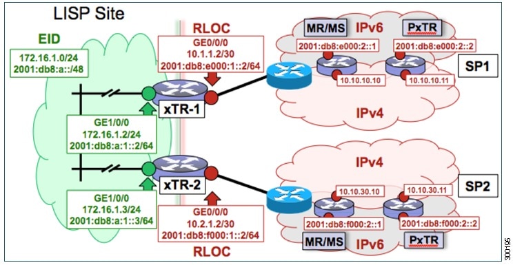
Perform this task to configure a multihomed LISP site with two xTRs, each with both an IPv4 and an IPv6 RLOC and both with an IPv4 and an IPv6 EID. In this task, a LISP site uses two edge routers. Each edge router is configured as an xTR (each performs as both an ITR and an ETR) and each also includes a single, dual stack (IPv4 and IPv6) connection to an upstream provider. (Two different providers are used in this example but the same upstream provider could be used for both connections.) Each xTR has an IPv4 RLOC and an IPv6 RLOC and both IPv4 and IPv6 EID prefixes are being used within the LISP site. However, because the site has both IPv4 and IPv6 RLOCs, it does not require a Proxy Ingress/Egress Tunnel Router (PxTR) LISP infrastructure for access to non-LISP IPv6 addresses. (The PxTR infrastructure can still be configured as a resiliency mechanism if desired.)
The LISP site registers to two map resolver/map server (MR/MS) devices in the network core using both IPv4 and IPv6 locators. The topology used in this multihomed LISP configuration is shown in the figure below.
The components illustrated in the topology shown in the figure are described below:
-
LISP site: - Two CPE routers make up the LISP site: xTR-1 and xTR-2.
- Both CPE routers function as LISP xTRs (that is, an ITR and an ETR).
- The LISP site is authoritative for both the IPv4 EID prefix of 172.16.1.0/24 and the IPv6 EID prefix 2001:db8:a::/48.
- Each LISP xTR has a single IPv4 RLOC connection and a single IPv6 RLOC connection to the core: the RLOC connections for xTR-1 to SP1 include an IPv4 RLOC, 10.1.1.2/30, and an IPv6 RLOC, 2001:db8:e000:1::2/64. The xTR-2 connections to SP2 include IPv4 RLOC 10.2.1.2/30 and IPv6 RLOC 2001:db8:f000:1::2/64.
- For this multihomed case, the LISP site policy specifies equal load-sharing between service provider (SP) links for ingress traffic engineering.
-
Mapping system: -
Two map resolver/map server systems are assumed to be available for the LISP xTR to configure. The MR/MSs have IPv4 RLOCs 10.10.10.10 and 10.10.30.10 and IPv6 RLOCs 2001:db8:e000:2::1 and 2001:db8:f000:2::1.
-
Mapping services are assumed to be provided as part of this LISP solution via a private mapping system or as a public LISP mapping system. From the perspective of the configuration of these LISP site xTRs, there is no difference.
Note
Map resolver and map server configurations are not shown here. See the "Configure a Private LISP Mapping System Using a Standalone Map Resolver/Map Server" section for information about map resolver and map server configuration.
- PxTR services are not required in this example since both xTRs have dual-stack connectivity to the core.
-
Perform the steps in this task (once through for each xTR in the LISP site) to enable and configure LISP ITR and ETR (xTR) functionality when using a LISP map resolver and map server for mapping services. The example configurations at the end of this task show the full configuration for two xTRs (xTR1 and xTR2).
1.
configure
terminal
2.
router
lisp
3.
database-mapping
EID-prefix/prefix-length
locator
priority
priority
weight
weight
4. Repeat Step 3 to configure a second IPv4 RLOC for the same xTR and IPv4 EID prefix.
5. Repeat Step 3 and Step 4 to configure the same RLOC connections, again, for the same xTR but, when repeating these two steps, associate the IPv6 EID prefix, 2001:db8:a::/48, instead of the IPv4 EID prefix.
6. Repeat Step 3, Step 4, and Step 5 to configure the second set of IPv4 and IPv6 RLOC connections on the same xTR for both the IPv4 and IPv6 EID prefixes.
7.
ipv4
itr
8.
ipv4
etr
9.
ipv4
itr
map-resolver
map-resolver-address
10. Repeat Step 9 to configure a second locator address of the LISP map resolver.
11. Repeat Step 9 and Step 10 to configure the IPv6 locator addresses of the LISP two map resolvers.
12.
ipv4
etr
map-server
map-server-address
key
key-type
authentication-key
13. Repeat Step 12 to configure a second locator address of the map server.
14. Repeat Step 12 and Step 13 to configure the IPv6 locator addresses of the two map servers.
15.
ipv6
itr
16.
ipv6
etr
17.
ipv6
itr
map-resolver
map-resolver-address
18. Repeat Step 17 to configure a second IPv6 locator address of the LISP map resolver.
19. Repeat Step 17 and Step18 to configure the IPv6 (instead of IPv4) locator addresses for the two map resolvers to which this router will send Map-Request messages for IPv6 EID-to-RLOC mapping resolutions.
20.
ipv6
etr
map-server
map-server-address
key
key-type
authentication-key
21. Repeat Step 20 to configure a second locator address of the LISP map server.
22. Repeat Steps 20 and 21 to configure the IPv6 locator addresses of the two map servers for which this router, acting as an IPv6 LISP ETR, will use to register to the LISP mapping system.
23.
exit
24.
ip
route
ipv4-prefix
next-hop
25.
exit
DETAILED STEPS
| Command or Action | Purpose | |||||
|---|---|---|---|---|---|---|
| Step 1 |
configure
terminal
Example: Router# configure terminal |
Enters global configuration mode. | ||||
| Step 2 |
router
lisp
Example: Router(config)# router lisp |
Enters LISP configuration mode ( software only). | ||||
| Step 3 |
database-mapping
EID-prefix/prefix-length
locator
priority
priority
weight
weight
Example: Router(config-router-lisp)# database-mapping 172.16.1.0/24 10.1.1.2 priority 1 weight 50 |
Configures an EID-to-RLOC mapping relationship and its associated traffic policy for this LISP site.
| ||||
| Step 4 | Repeat Step 3
to configure a second IPv4 RLOC for the same xTR and IPv4 EID prefix.
Example: Router(config-router-lisp)# database-mapping 172.16.1.0/24 10.2.1.2 priority 1 weight 50 |
Configures an EID-to-RLOC mapping relationship and its associated traffic policy for an xTR on this LISP site.
| ||||
| Step 5 | Repeat Step 3
and Step 4 to configure the same RLOC connections, again, for the same xTR but,
when repeating these two steps, associate the IPv6 EID prefix, 2001:db8:a::/48,
instead of the IPv4 EID prefix.
Example: Router(config-router-lisp)# database-mapping 2001:db8:a::/48 10.1.1.2 priority 1 weight 50 Example: Router(config-router-lisp)# database-mapping 2001:db8:a::/48 10.2.1.2 priority 1 weight 50 |
— | ||||
| Step 6 | Repeat Step 3, Step 4, and Step 5 to configure the second set of IPv4 and IPv6 RLOC connections on the same xTR for both the IPv4 and IPv6 EID prefixes. |
— | ||||
| Step 7 |
ipv4
itr
Example: Router(config-router-lisp)# ipv4 itr |
Enables LISP ITR functionality for the IPv4 address family. | ||||
| Step 8 |
ipv4
etr
Example: Router(config-router-lisp)# ipv4 etr |
Enables LISP ETR functionality for the IPv4 address family. | ||||
| Step 9 |
ipv4
itr
map-resolver
map-resolver-address
Example: Router(config-router-lisp)# ipv4 itr map-resolver 10.10.10.10 |
Configures a locator address for the LISP map resolver to which this router will send Map-Request messages for IPv4 EID-to-RLOC mapping resolutions.
| ||||
| Step 10 | Repeat Step 9
to configure a second locator address of the LISP map resolver.
Example: Router(config-router-lisp)# ipv4 itr map-resolver 10.10.30.10 |
Configures a second locator address for the LISP map resolver to which this router will send Map-Request messages for IPv4 EID-to-RLOC mapping resolutions. | ||||
| Step 11 | Repeat Step 9 and Step 10 to configure the IPv6 locator addresses of the LISP two map resolvers. |
— | ||||
| Step 12 |
ipv4
etr
map-server
map-server-address
key
key-type
authentication-key
Example: Router(config-router-lisp)# ipv4 etr map-server 10.10.10.10 key 0 some-key |
Configures a locator address for the LISP map server and an authentication key that this router, acting as an IPv4 LISP ETR, will use to register with the LISP mapping system.
| ||||
| Step 13 | Repeat Step
12 to configure a second locator address of the map server.
Example: Router(config-router-lisp)# ipv4 etr map-server 10.10.30.10 key 0 some-key |
Configures a second IPv4 locator address of the LISP map server and the authentication key that this router, acting as an IPv4 LISP ETR, will use to register with the LISP mapping system. | ||||
| Step 14 | Repeat Step
12 and Step 13 to configure the IPv6 locator addresses of the two map servers.
Example: ipv4 etr map-server 2001:db8:e000:2::1 key 0 some-xtr-key Example: ipv4 etr map-server 2001:db8:f000:2::1 key 0 some-xtr-key |
— | ||||
| Step 15 |
ipv6
itr
Example: Router(config-router-lisp)# ipv6 itr |
Enables LISP ITR functionality for the IPv6 address family. | ||||
| Step 16 |
ipv6
etr
Example: Router(config-router-lisp)# ipv6 etr |
Enables LISP ETR functionality for the IPv6 address family. | ||||
| Step 17 |
ipv6
itr
map-resolver
map-resolver-address
Example: Router(config-router-lisp)# ipv6 itr map-resolver 10.10.10.10 |
Configures a locator address for the LISP map resolver to which this router will send Map-Request messages for IPv6 EID-to-RLOC mapping resolutions.
| ||||
| Step 18 | Repeat Step
17 to configure a second IPv6 locator address of the LISP map resolver.
Example: Router(config-router-lisp)# ipv6 itr map-resolver 10.10.30.10 |
Configures a second locator address of the map resolver to which this router will send Map-Request messages for IPv6 EID-to-RLOC mapping resolutions. | ||||
| Step 19 | Repeat Step
17 and Step18 to configure the IPv6 (instead of IPv4) locator addresses for the
two map resolvers to which this router will send Map-Request messages for IPv6
EID-to-RLOC mapping resolutions.
Example: ipv6 itr map-resolver 2001:db8:e000:2::1 Example: ipv6 itr map-resolver 2001:db8:f000:2::1 |
— | ||||
| Step 20 |
ipv6
etr
map-server
map-server-address
key
key-type
authentication-key
Example: Router(config-router-lisp)# ipv6 etr map-server 10.10.10.10 key 0 some-key |
Configures a locator address for the LISP map server and an authentication key that this router, acting as an IPv6 LISP ETR, will use to register to the LISP mapping system.
| ||||
| Step 21 | Repeat Step
20 to configure a second locator address of the LISP map server.
Example: Router(config-router-lisp)# ipv6 etr map-server 10.10.30.10 key 0 some-key |
Configures a second locator address for the LISP map server and an authentication key that this router, acting as an IPv6 LISP ETR, will use to register with the LISP mapping system. | ||||
| Step 22 | Repeat Steps
20 and 21 to configure the IPv6 locator addresses of the two map servers for
which this router, acting as an IPv6 LISP ETR, will use to register to the LISP
mapping system.
Example: ipv6 etr map-server 2001:db8:e000:2::1 key 0 some-xtr-key Example: ipv6 etr map-server 2001:db8:f000:2::1 key 0 some-xtr-key |
— | ||||
| Step 23 |
exit
Example: Router(config-router-lisp)# exit |
Exits LISP configuration mode and returns to global configuration mode. | ||||
| Step 24 |
ip
route
ipv4-prefix
next-hop
Example: Router(config)# ip route 0.0.0.0 0.0.0.0 10.1.1.1 |
Configures a default route to the upstream next hop for all IPv4 destinations. | ||||
| Step 25 |
exit
Example: Router(config)# exit |
Exits global configuration mode. |
Example:
The examples below show the complete configuration for the LISP topology illustrated in the figure above and in this task:
Example configuration for xTR-1:
!
hostname xTR-1
!
no ip domain lookup
ip cef
ipv6 unicast-routing
ipv6 cef
!
interface Loopback0
 ip address 172.17.1.1 255.255.255.255
!
interface LISP0
!
interface GigabitEthernet0/0/0
 description Link to SP1 (RLOC)
 ip address 10.1.1.2 255.255.255.252
 ipv6 address 2001:db8:e000:1::2/64
!
interface GigabitEthernet1/0/0
 description Link to Site (EID)
 ip address 172.16.1.2 255.255.255.0
 ipv6 address 2001:db8:a:1::2/64
!
router lisp
 database-mapping 172.16.1.0/24 10.1.1.2 priority 1 weight 50
 database-mapping 172.16.1.0/24 10.2.1.2 priority 1 weight 50
 database-mapping 2001:db8:a::/48 10.1.1.2 priority 1 weight 50
 database-mapping 2001:db8:a::/48 10.2.1.2 priority 1 weight 50
 database-mapping 172.16.1.0/24 2001:db8:e000:1::2 priority 1 weight 50
 database-mapping 172.16.1.0/24 2001:db8:f000:1::2 priority 1 weight 50
 database-mapping 2001:db8:a::/48 2001:db8:e000:1::2 priority 1 weight 50
 database-mapping 2001:db8:a::/48 2001:db8:f000:1::2 priority 1 weight 50
 ipv4 itr
 ipv4 etr
 ipv4 itr map-resolver 10.10.10.10
 ipv4 itr map-resolver 10.10.30.10
 ipv4 itr map-resolver 2001:db8:e000:2::1
 ipv4 itr map-resolver 2001:db8:f000:2::1
 ipv4 etr map-server 10.10.10.10 key 0 some-xtr-key
 ipv4 etr map-server 10.10.30.10 key 0 some-xtr-key
 ipv4 etr map-server 2001:db8:e000:2::1 key 0 some-xtr-key
 ipv4 etr map-server 2001:db8:f000:2::1 key 0 some-xtr-key
 ipv6 itr
 ipv6 etr
 ipv6 itr map-resolver 10.10.10.10
 ipv6 itr map-resolver 10.10.30.10
 ipv6 itr map-resolver 2001:db8:e000:2::1
 ipv6 itr map-resolver 2001:db8:f000:2::1
 ipv6 etr map-server 10.10.10.10 key 0 some-xtr-key
 ipv6 etr map-server 10.10.30.10 key 0 some-xtr-key
 ipv6 etr map-server 2001:db8:e000:2::1 key 0 some-xtr-key
 ipv6 etr map-server 2001:db8:f000:2::1 key 0 some-xtr-key
 exit
!
ip route 0.0.0.0 0.0.0.0 10.1.1.1
!
ipv6 route ::/0 2001:db8:e000:1::1
!
Example configuration for xTR-2:
!
hostname xTR-2
!
no ip domain lookup
ip cef
ipv6 unicast-routing
ipv6 cef
!
interface Loopback0
 ip address 172.17.1.2 255.255.255.255
!
interface LISP0
!
interface GigabitEthernet0/0/0
 description Link to SP2 (RLOC)
 ip address 10.2.1.2 255.255.255.252
 ipv6 address 2001:db8:f000:1::2/64
!
interface GigabitEthernet1/0/0
 description Link to Site (EID)
 ip address 172.16.1.3 255.255.255.0
 ipv6 address 2001:db8:a:1::3/64
!
router lisp
 database-mapping 172.16.1.0/24 10.1.1.2 priority 1 weight 50
 database-mapping 172.16.1.0/24 10.2.1.2 priority 1 weight 50
 database-mapping 2001:db8:a::/48 10.1.1.2 priority 1 weight 50
 database-mapping 2001:db8:a::/48 10.2.1.2 priority 1 weight 50
 database-mapping 172.16.1.0/24 2001:db8:e000:1::2 priority 1 weight 50
 database-mapping 172.16.1.0/24 2001:db8:f000:1::2 priority 1 weight 50
 database-mapping 2001:db8:a::/48 2001:db8:e000:1::2 priority 1 weight 50
 database-mapping 2001:db8:a::/48 2001:db8:f000:1::2 priority 1 weight 50
 ipv4 itr
 ipv4 etr
 ipv4 itr map-resolver 10.10.10.10
 ipv4 itr map-resolver 10.10.30.10
 ipv4 itr map-resolver 2001:db8:e000:2::1
 ipv4 itr map-resolver 2001:db8:f000:2::1
 ipv4 etr map-server 10.10.10.10 key 0 some-xtr-key
 ipv4 etr map-server 10.10.30.10 key 0 some-xtr-key
 ipv4 etr map-server 2001:db8:e000:2::1 key 0 some-xtr-key
 ipv4 etr map-server 2001:db8:f000:2::1 key 0 some-xtr-key
 ipv6 itr
 ipv6 etr
 ipv6 itr map-resolver 10.10.10.10
 ipv6 itr map-resolver 10.10.30.10
 ipv6 itr map-resolver 2001:db8:e000:2::1
 ipv6 itr map-resolver 2001:db8:f000:2::1
 ipv6 etr map-server 10.10.10.10 key 0 some-xtr-key
 ipv6 etr map-server 10.10.30.10 key 0 some-xtr-key
 ipv6 etr map-server 2001:db8:e000:2::1 key 0 some-xtr-key
 ipv6 etr map-server 2001:db8:f000:2::1 key 0 some-xtr-key
 exit
!
ip route 0.0.0.0 0.0.0.0 10.2.1.1
!
ipv6 route ::/0 2001:db8:f000:1::1
!
Configure a Private LISP Mapping System Using a Standalone Map Resolver/Map Server
Perform this task to configure and enable standalone LISP map resolver/map server (MR/MS) functionality for both IPv4 and IPv6 address families. In this task, a Cisco device is configured as a standalone MR/MS for a private LISP mapping system. Because the MR/MS is configured as a standalone device, it has no need for LISP alternative logical topology (ALT) connectivity. All relevant LISP sites must be configured to register with this map server so that this map server has full knowledge of all registered EID prefixes within the (assumed) private LISP system. However, because this device is functioning as a map resolver/map server, the data structure associated with an ALT virtual routing and forwarding (VRF) table must still be configured to hold LISP EIDs for registered sites.
The map resolver/map server is configured with both IPv4 and IPv6 RLOC addresses. The topology used in this most basic LISP MR/MS configuration is shown in the figure below.

The components illustrated in the topology shown in the figure are described below, although the map resolver is configured separately:
The LISP device is configured to function as a standalone map resolver/map server (MR/MS).
The xTRs in the LISP site are assumed to be registered to this map server. That is, the xTR registers the IPv4 EID prefix of 172.16.1.0/24 and, when IPv6 EIDs are used, the xTR also registers the IPv6 EID of prefix 2001:db8:a::/48.
The MR/MS has an IPv4 locator of 10.10.10.10/24 and an IPv6 locator of 2001:db8:e000:2::1/64.
1.
configure
terminal
2.
vrf
definition
vrf-name
3.
address-family
ipv4
[unicast]
4.
exit-address-family
5.
address-family
ipv6
6.
exit-address-family
7.
exit
8.
router lisp
9.
ipv4
alt-vrf
vrf-name
10.
ipv4
map-server
11.
ipv4
map-resolver
12.
ipv6
alt-vrf
vrf-name
13.
ipv6
map-server
14.
ipv6
map-resolver
15.
site
site-name
16.
eid-prefix
EID-prefix
17.
authentication-key [key-type]
authentication-key
18.
exit
19. Repeat Steps 15 through 18 to configure additional LISP sites.
20.
exit
21.
ip
route
ipv4-prefix
next-hop
22.
ipv6
route
ipv6-prefix
next-hop
23.
exit
DETAILED STEPS
| Command or Action | Purpose | |||||
|---|---|---|---|---|---|---|
| Step 1 |
configure
terminal
Example: Router# configure terminal |
Enters global configuration mode. | ||||
| Step 2 |
vrf
definition
vrf-name
Example: Router(config)# vrf definition lisp |
Creates a virtual routing and forwarding (VRF) table and enters VRF configuration mode. | ||||
| Step 3 |
address-family
ipv4
[unicast]
Example: Router(config-vrf)# address-family ipv4 |
Enters VRF IPv4 address family configuration mode to specify an IPv4 address family for a VRF table. | ||||
| Step 4 |
exit-address-family
Example: Router(config-vrf-af)# exit-address-family |
Exits VRF IPv4 address family configuration mode and returns to VRF configuration mode. | ||||
| Step 5 |
address-family
ipv6
Example: Router(config-vrf)# address-family ipv6 |
Enters VRF IPv6 address family configuration mode to specify an IPv6 address family for a VRF table. | ||||
| Step 6 |
exit-address-family
Example: Router(config-vrf-af)# exit-address-family |
Exits VRF IPv6 address family configuration mode and returns to VRF configuration mode. | ||||
| Step 7 |
exit
Example: Router(config-vrf)# exit |
Exits VRF configuration mode and enters global configuration mode. | ||||
| Step 8 |
router lisp
Example: Router(config)# router lisp |
Enters LISP configuration mode ( software only). | ||||
| Step 9 |
ipv4
alt-vrf
vrf-name
Example: Router(config-router-lisp)# ipv4 alt-vrf lisp |
Associates a VRF table with the LISP ALT for IPv4 EIDs. | ||||
| Step 10 |
ipv4
map-server
Example: Router(config-router-lisp)# ipv4 map-server |
Enables LISP map server functionality for EIDs in the IPv4 address family. | ||||
| Step 11 |
ipv4
map-resolver
Example: Router(config-router-lisp)# ipv4 map-resolver |
Enables LISP map resolver functionality for EIDs in the IPv4 address family. | ||||
| Step 12 |
ipv6
alt-vrf
vrf-name
Example: Router(config-router-lisp)# ipv6 alt-vrf lisp |
Associates a VRF table with the LISP ALT for IPv6 EIDs. | ||||
| Step 13 |
ipv6
map-server
Example: Router(config-router-lisp)# ipv6 map-server |
Enables LISP map server functionality for EIDs in the IPv6 address family. | ||||
| Step 14 |
ipv6
map-resolver
Example: Router(config-router-lisp)# ipv6 map-resolver |
Enables LISP map resolver functionality for EIDs in the IPv6 address family. | ||||
| Step 15 |
site
site-name
Example: Router(config-router-lisp)# site Site-1 |
Specifies a LISP site named Site-1 and enters LISP site configuration mode.
| ||||
| Step 16 |
eid-prefix
EID-prefix
Example: Router(config-router-lisp-site)# eid-prefix 172.16.1.0/24 |
Configures an IPv4 or IPv6 EID prefix associated with this LISP site.
| ||||
| Step 17 |
authentication-key [key-type]
authentication-key
Example: Router(config-router-lisp-site)# authentication-key 0 some-key |
Configures the authentication key associated with this site.
| ||||
| Step 18 |
exit
Example: Router(config-router-lisp-site)# exit |
Exits LISP site configuration mode and returns to LISP configuration mode. | ||||
| Step 19 | Repeat Steps 15 through 18 to configure additional LISP sites. | — | ||||
| Step 20 |
exit
Example: Router(config-router-lisp)# exit |
Exits LISP configuration mode and returns to global configuration mode. | ||||
| Step 21 |
ip
route
ipv4-prefix
next-hop
Example: Router(config)# ip route 0.0.0.0 0.0.0.0 10.1.1.1 |
Configures an IPv4 static route. | ||||
| Step 22 |
ipv6
route
ipv6-prefix
next-hop
Example: Router(config)# ipv6 route ::/0 2001:db8:e000:1::1 |
Configures an IPv6 static route. | ||||
| Step 23 |
exit
Example: Router(config)# exit |
Exits global configuration mode and returns to privileged EXEC mode. |
Example:
The example below shows the complete configuration for the LISP topology illustrated in the figure above and in this task. However, this example is for a full configuration of a standalone LISP MR/MS and includes some basic IPv4 and IPv6 configuration not covered in this task:
!
hostname MR-MS
!
vrf definition lisp
!
 address-family ipv4
 exit-address-family
 !
 address-family ipv6
 exit-address-family
!
no ip domain lookup
ip cef
ipv6 unicast-routing
ipv6 cef
!
interface Loopback0
 ip address 172.17.2.1 255.255.255.255
!
interface LISP0
!
interface GigabitEthernet0/0/0
 description Link to SP1 (RLOC)
 ip address 10.10.10.10 255.255.255.0
 ipv6 address 2001:db8:e000:2::1/64
!
router lisp
 site Site-1
  authentication-key some-key
  eid-prefix 172.16.1.0/24
  eid-prefix 2001:db8:a::/48
  exit
 !
 site Site-2
  authentication-key another-key
  eid-prefix 172.16.2.0/24
  eid-prefix 2001:db8:b::/48
  exit
 !
!---more LISP site configs---
 !
 ipv4 map-server
 ipv4 map-resolver
 ipv4 alt-vrf lisp
 ipv6 map-server
 ipv6 map-resolver
 ipv6 alt-vrf lisp
 exit
!
ip route 0.0.0.0 0.0.0.0 10.10.10.1
!
ipv6 route ::/0 2001:db8:e000:2::fof
Configure a Public Mapping System Using Separate ALT-Connected Map Resolver and Map Server Devices
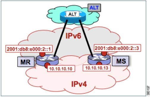
The following tasks show how to configure a map resolver (MR) and a map server (MS) on separate devices, each using LISP alternative logical topology (ALT) connectivity. The MR and MS share their EID prefix information via the LISP ALT connectivity, which is typical of a public LISP deployment model where higher performance and scalability (for tasks such as the handling of Map-Request messages) is required. The LISP ALT is implemented as an overlay virtualized network using GRE tunnels and BGP, which allows for separation of EID prefixes from the underlying core network.
Configuring an ALT-Connected LISP Map Resolver
Perform this task to configure LISP alternative logical topology (ALT) map resolver functionality for both IPv4 and IPv6 address family mapping services.
Note | You must also configure an ALT-connected LISP map server (see the Configuring an ALT-Connected LISP Map Server task). |
In the figure below, the map resolver (MR) and map server (MS) are configured on separate devices and share their EID prefix information via connectivity.
The map resolver illustrated in the topology shown in the figure is described below; the map server and LISP ALT are configured in separate tasks:
Two LISP devices are configured, one as an MS and the other as an MR.
The MS has an IPv4 locator of 10.10.10.13/24 and an IPv6 locator of 2001:db8:e000:2::3/64.
The MR has an IPv4 locator of 10.10.10.10/24 and an IPv6 locator of 2001:db8:e000:2::1/64.
Assume that the xTRs in the LISP site register to this map server. That is, the xTR registers the IPv4 EID-prefix of 172.16.1.0/24 and, when IPv6 EIDs are used, the xTR registers the IPv6 EID-prefix of 2001:db8:a::/48.
NoteThe configuration of the xTR must be changed to use the MS RLOC for its map server configuration and the MR RLOC for its map resolver configuration. For example:
Other Infrastructure
1.
configure
terminal
2.
vrf
definition
vrf-name
3.
rd
route-distinguisher
4.
address-family
ipv4
[unicast]
5.
exit-address-family
6.
address-family
ipv6
7.
exit-address-family
8.
exit
9.
interface
type
number
10.
vrf
forwarding
vrf-name
11.
ip
address
ip-address
mask
12.
ipv6
address
ipv6-address/mask
13.
tunnel
source
interface-type
interface-number
14.
tunnel destination
ipv4-address
15.
exit
16.
router lisp
17.
ipv4
map-resolver
18.
ipv4
alt-vrf
vrf-name
19.
ipv6
map-resolver
20.
ipv6
alt-vrf
vrf-name
21.
exit
22.
router
bgp
autonomous-system-number
23.
address-family
ipv4
[unicast |
multicast
|
vrf
vrf-name]
24.
neighbor
ip-address
remote-as
autonomous-system-number
25.
neighbor
ip-address
activate
26.
exit
27.
address-family
ipv6
vrf
vrf-name
28.
neighbor
ip-address
remote-as
autonomous-system-number
29.
neighbor
ip-address
activate
30.
exit
31.
exit
32.
ip
route
ipv4-prefix
next-hop
33.
ipv6
route
ipv6-prefix
next-hop
34.
exit
DETAILED STEPS
| Command or Action | Purpose | |
|---|---|---|
| Step 1 |
configure
terminal
Example: Router# configure terminal |
Enters global configuration mode. |
| Step 2 |
vrf
definition
vrf-name
Example: Router(config)# vrf definition lisp |
Creates a virtual routing and forwarding (VRF) table and enters VRF configuration mode. |
| Step 3 |
rd
route-distinguisher
Example: Router(config-vrf)# rd 1:1 |
Creates routing and forwarding tables for a VRF. |
| Step 4 |
address-family
ipv4
[unicast]
Example: Router(config-vrf)# address-family ipv4 |
Enters VRF IPv4 address family configuration mode to specify an IPv4 address family for a VRF table. |
| Step 5 |
exit-address-family
Example: Router(config-vrf-af)# exit-address-family |
Exits VRF IPv4 address family configuration mode and returns to VRF configuration mode. |
| Step 6 |
address-family
ipv6
Example: Router(config-vrf)# address-family ipv6 |
Enters VRF IPv6 address family configuration mode to specify an IPv6 address family for a VRF table. |
| Step 7 |
exit-address-family
Example: Router(config-vrf-af)# exit-address-family |
Exits VRF IPv6 address family configuration mode and returns to VRF configuration mode. |
| Step 8 |
exit
Example: Router(config-vrf)# exit |
Exits VRF configuration mode and enters global configuration mode. |
| Step 9 |
interface
type
number
Example: Router(config)# interface tunnel 192 |
Specifies the interface type of tunnel and the interface number and enters interface configuration mode. |
| Step 10 |
vrf
forwarding
vrf-name
Example: Router(config-if)# vrf forwarding lisp |
Associates a VRF instance configured in Step 2 with the tunnel interface configured in Step 9. |
| Step 11 |
ip
address
ip-address
mask
Example: Router(config-if)# ip address 192.168.1.1 255.255.255.252 |
Configures an IPv4 address for the tunnel interface. |
| Step 12 |
ipv6
address
ipv6-address/mask
Example: Router(config-if)# ipv6 address 2001:db8:ffff::1/64 |
Configures an IPv6 address for the tunnel interface. |
| Step 13 |
tunnel
source
interface-type
interface-number
Example: Router(config-if)# tunnel source GigabitEthernet 0/0/0 |
Configures the tunnel source. |
| Step 14 |
tunnel destination
ipv4-address
Example: Router(config-if)# tunnel destination 10.10.10.13 |
Configures the tunnel destination IPv4 address for the tunnel interface. |
| Step 15 |
exit
Example: Router(config-if)# exit |
Exits interface configuration mode and enters global configuration mode. |
| Step 16 |
router lisp
Example: Router(config)# router lisp |
Enters LISP configuration mode ( software only). |
| Step 17 |
ipv4
map-resolver
Example: Router(config-router-lisp)# ipv4 map-resolver |
Enables LISP map resolver functionality for EIDs in the IPv4 address family. |
| Step 18 |
ipv4
alt-vrf
vrf-name
Example: Router(config-router-lisp)# ipv4 alt-vrf lisp |
Associates a VRF table with the LISP ALT for IPv4 EIDs. |
| Step 19 |
ipv6
map-resolver
Example: Router(config-router-lisp)# ipv6 map-resolver |
Enables LISP map resolver functionality for EIDs in the IPv6 address family. |
| Step 20 |
ipv6
alt-vrf
vrf-name
Example: Router(config-router-lisp)# ipv6 alt-vrf lisp |
Associates a VRF table with the LISP ALT for IPv6 EIDs. |
| Step 21 |
exit
Example: Router(config-router-lisp)# exit |
Exits LISP configuration mode and returns to global configuration mode. |
| Step 22 |
router
bgp
autonomous-system-number
Example: Router(config)# router bgp 65010 |
Enters router configuration mode for the specified routing process. |
| Step 23 |
address-family
ipv4
[unicast |
multicast
|
vrf
vrf-name]
Example: Router(config-router)# address-family ipv4 vrf lisp |
|
| Step 24 |
neighbor
ip-address
remote-as
autonomous-system-number
Example: Router(config-router-af)# neighbor 192.168.1.2 remote-as 65011 |
Adds the IP address of the neighbor in the specified autonomous system to the IPv4 multiprotocol BGP neighbor table of the local router. |
| Step 25 |
neighbor
ip-address
activate
Example: Router(config-router-af)# neighbor 192.168.1.2 activate |
Enables the neighbor to exchange prefixes for the IPv4 unicast address family. |
| Step 26 |
exit
Example: Router(config-router-af)# exit |
Exits IPv4 address family configuration mode and returns to router configuration mode. |
| Step 27 |
address-family
ipv6
vrf
vrf-name
Example: Router(config-router)# address-family ipv6 vrf lisp |
|
| Step 28 |
neighbor
ip-address
remote-as
autonomous-system-number
Example: Router(config-router-af)# neighbor 2001:db8:ffff::2 remote-as 65011 |
Adds the IPv6 address of the neighbor in the specified autonomous system to the IPv6 multiprotocol BGP neighbor table of the local router. |
| Step 29 |
neighbor
ip-address
activate
Example: Router(config-router-af)# neighbor 2001:db8:ffff::2 activate |
Enables the neighbor to exchange prefixes for the IPv6 unicast address family. |
| Step 30 |
exit
Example: Router(config-router-af)# exit |
Exits address family configuration mode and returns to router configuration mode. |
| Step 31 |
exit
Example: Router(config-router)# exit |
Exits router configuration mode and returns to global configuration mode. |
| Step 32 |
ip
route
ipv4-prefix
next-hop
Example: Router(config)# ip route 0.0.0.0 0.0.0.0 10.10.10.1 |
Configures an IPv4 static route. |
| Step 33 |
ipv6
route
ipv6-prefix
next-hop
Example: Router(config)# ipv6 route ::/0 2001:db8:e000:2::f0f |
Configures an IPv6 static route. |
| Step 34 |
exit
Example: Router(config)# exit |
Exits global configuration mode and returns to privileged EXEC mode. |
Examples
The example below shows the full configuration for a LISP map resolver including some basic IP and IPv6 configuration not included in the task table for this task:
!
vrf definition lisp
 rd 1:1
 !
 address-family ipv4
 exit-address-family
 !
 address-family ipv6
 exit-address-family
!
no ip domain lookup
ip cef
ipv6 unicast-routing
ipv6 cef
!
interface Loopback0
 no ip address
!
interface Tunnel192
 vrf forwarding lisp
 ip address 192.168.1.1 255.255.255.252
 ipv6 address 2001:db8:ffff::1/64
 tunnel source GigabitEthernet 0/0/0
 tunnel destination 10.10.10.13
!
interface GigabitEthernet 0/0/0
 description Link to SP1 (RLOC)
 ip address 10.10.10.10 255.255.255.0
 ipv6 address 2001:db8:e000:2::1/64
!
router lisp
 ipv4 map-resolver
 ipv4 alt-vrf lisp
 ipv6 map-resolver
 ipv6 alt-vrf lisp
 exit
!
router bgp 65010
 bgp asnotation dot
 bgp log-neighbor-changes
 !
 address-family ipv4 vrf lisp
  neighbor 192.168.1.2 remote-as 65011
  neighbor 192.168.1.2 activate
 exit-address-family
 !
 address-family ipv6 vrf lisp
  neighbor 2001:db8:ffff::2 remote-as 65011
  neighbor 2001:db8:ffff::2 activate
 exit-address-family
!
ip route 0.0.0.0 0.0.0.0 10.10.10.1
!
ipv6 route ::/0 2001:db8:e000:2::f0f
!
Configuring an ALT-Connected LISP Map Server
Perform this task to configure LISP alternative logical topology (ALT) map server functionality for both IPv4 and IPv6 address family mapping services.
Note | You must also configure an ALT-connected LISP map resolver (see the Configuring an ALT-Connected LISP Map Resolver task). |
In the figure below, the map resolver (MR) and map server (MS) are configured on separate devices and share their EID prefix information via connectivity.
The map server illustrated in the topology shown in the figure is described below; the map resolver and LISP ALT are configured in separate tasks:
Two LISP devices are configured, one as an MS and the other as an MR.
The MS has an IPv4 locator of 10.10.10.13/24 and an IPv6 locator of 2001:db8:e000:2::3/64.
The MR has an IPv4 locator of 10.10.10.10/24 and an IPv6 locator of 2001:db8:e000:2::1/64.
Assume that the xTRs in the LISP site register to this map server. That is, the xTR registers the IPv4 EID-prefix of 172.16.1.0/24 and, when IPv6 EIDs are used, the xTR registers the IPv6 EID-prefix of 2001:db8:a::/48.
NoteThe configuration of the xTR must be changed to use the MS RLOC for its map server configuration and the MR RLOC for its map resolver configuration. For example:
Other Infrastructure
1.
configure
terminal
2.
vrf
definition
vrf-name
3.
rd
route-distinguisher
4.
address-family
ipv4
[unicast]
5.
exit-address-family
6.
address-family
ipv6
7.
exit-address-family
8.
exit
9.
interface
type
number
10.
vrf
forwarding
vrf-name
11.
ip
address
ip-address
mask
12.
ipv6
address
ipv6-address/mask
13.
tunnel
source
interface-type
interface-number
14.
tunnel destination
ipv4-address
15.
exit
16.
router lisp
17.
ipv4
map-server
18.
ipv4
alt-vrf
vrf-name
19.
ipv6
map-server
20.
ipv6
alt-vrf
vrf-name
21.
site
site-name
22.
eid-prefix
EID-prefix
23.
authentication-key
key-type
authentication-key
24.
exit
25. Repeat Steps 21 through 24 to configure additional LISP sites.
26.
exit
27.
router
bgp
autonomous-system-number
28.
address-family
ipv4
[unicast |
multicast
|
vrf
vrf-name]
29.
redistribute
lisp
30.
neighbor
ip-address
remote-as
autonomous-system-number
31.
neighbor
ip-address
activate
32.
exit
33.
address-family
ipv6
vrf
vrf-name
34.
redistribute
lisp
35.
neighbor
ip-address
remote-as
autonomous-system-number
36.
neighbor
ip-address
activate
37.
exit
38.
exit
39.
ip
route
ipv4-prefix
next-hop
40.
ipv6
route
ipv6-prefix
next-hop
41.
exit
DETAILED STEPS
| Command or Action | Purpose | |||||
|---|---|---|---|---|---|---|
| Step 1 |
configure
terminal
Example: Router# configure terminal |
Enters global configuration mode. | ||||
| Step 2 |
vrf
definition
vrf-name
Example: Router(config)# vrf definition lisp |
Creates a virtual routing and forwarding (VRF) table and enters VRF configuration mode. | ||||
| Step 3 |
rd
route-distinguisher
Example: Router(config-vrf)# rd 1:1 |
Creates routing and forwarding tables for a VRF. | ||||
| Step 4 |
address-family
ipv4
[unicast]
Example: Router(config-vrf)# address-family ipv4 |
Enters VRF IPv4 address family configuration mode to specify an IPv4 address family for a VRF table. | ||||
| Step 5 |
exit-address-family
Example: Router(config-vrf-af)# exit-address-family |
Exits VRF IPv4 address family configuration mode and returns to VRF configuration mode. | ||||
| Step 6 |
address-family
ipv6
Example: Router(config-vrf)# address-family ipv6 |
Enters VRF IPv6 address family configuration mode to specify an IPv6 address family for a VRF table. | ||||
| Step 7 |
exit-address-family
Example: Router(config-vrf-af)# exit-address-family |
Exits VRF IPv6 address family configuration mode and returns to VRF configuration mode. | ||||
| Step 8 |
exit
Example: Router(config-vrf)# exit |
Exits VRF configuration mode and enters global configuration mode. | ||||
| Step 9 |
interface
type
number
Example: Router(config)# interface tunnel 191 |
Specifies the interface type of tunnel and the interface number and enters interface configuration mode. | ||||
| Step 10 |
vrf
forwarding
vrf-name
Example: Router(config-if)# vrf forwarding lisp |
Associates a VRF instance configured in Step 2 with the tunnel interface configured in Step 9. | ||||
| Step 11 |
ip
address
ip-address
mask
Example: Router(config-if)# ip address 192.168.1.6 255.255.255.252 |
Configures an IPv4 address for the tunnel interface. | ||||
| Step 12 |
ipv6
address
ipv6-address/mask
Example: Router(config-if)# ipv6 address 2001:DB8:ffff::6/64 |
Configures an IPv6 address for the tunnel interface. | ||||
| Step 13 |
tunnel
source
interface-type
interface-number
Example: Router(config-if)# tunnel source GigabitEthernet 0/0/0 |
Configures the tunnel source. | ||||
| Step 14 |
tunnel destination
ipv4-address
Example: Router(config-if)# tunnel destination 10.10.10.13 |
Configures the tunnel destination IPv4 address for the tunnel interface. | ||||
| Step 15 |
exit
Example: Router(config-if)# exit |
Exits interface configuration mode and enters global configuration mode. | ||||
| Step 16 |
router lisp
Example: Router(config)# router lisp |
Enters LISP configuration mode ( software only). | ||||
| Step 17 |
ipv4
map-server
Example: Router(config-router-lisp)# ipv4 map-server |
Enables LISP map server functionality for EIDs in the IPv4 address family. | ||||
| Step 18 |
ipv4
alt-vrf
vrf-name
Example: Router(config-router-lisp)# ipv4 alt-vrf lisp |
Associates a VRF table with the LISP ALT for IPv4 EIDs. | ||||
| Step 19 |
ipv6
map-server
Example: Router(config-router-lisp)# ipv6 map-server |
Enables LISP map server functionality for EIDs in the IPv6 address family. | ||||
| Step 20 |
ipv6
alt-vrf
vrf-name
Example: Router(config-router-lisp)# ipv6 alt-vrf lisp |
Associates a VRF table with the LISP ALT for IPv6 EIDs. | ||||
| Step 21 |
site
site-name
Example: Router(config-router-lisp)# site Site-1 |
Specifies a LISP site and enters LISP site configuration mode.
| ||||
| Step 22 |
eid-prefix
EID-prefix
Example: Router(config-router-lisp-site)# eid-prefix 172.16.1.0/24 |
Configures an IPv4 or IPv6 EID prefix associated with this LISP site.
| ||||
| Step 23 |
authentication-key
key-type
authentication-key
Example: Router(config-router-lisp-site)# authentication-key 0 some-key |
Configures the authentication key associated with this site.
| ||||
| Step 24 |
exit
Example: Router(config-router-lisp-site)# exit |
Exits LISP site configuration mode and returns to LISP configuration mode. | ||||
| Step 25 | Repeat Steps 21 through 24 to configure additional LISP sites. | — | ||||
| Step 26 |
exit
Example: Router(config-router-lisp)# exit |
Exits LISP configuration mode and returns to global configuration mode. | ||||
| Step 27 |
router
bgp
autonomous-system-number
Example: Router(config)# router bgp 65011 |
Enters router configuration mode for the specified routing process. | ||||
| Step 28 |
address-family
ipv4
[unicast |
multicast
|
vrf
vrf-name]
Example: Router(config-router)# address-family ipv4 vrf lisp |
| ||||
| Step 29 |
redistribute
lisp
Example: Router(config-router-af)# redistribute lisp |
Redistributes EID prefixes known to LISP into BGP. | ||||
| Step 30 |
neighbor
ip-address
remote-as
autonomous-system-number
Example: Router(config-router-af)# neighbor 192.168.1.1 remote-as 65010 |
Adds the IP address of the neighbor in the specified autonomous system to the IPv4 multiprotocol BGP neighbor table of the local router. | ||||
| Step 31 |
neighbor
ip-address
activate
Example: Router(config-router-af)# neighbor 192.168.1.1 activate |
Enables the neighbor to exchange prefixes for the IPv4 unicast address family. | ||||
| Step 32 |
exit
Example: Router(config-router-af)# exit |
Exits address family configuration mode and returns to router configuration mode. | ||||
| Step 33 |
address-family
ipv6
vrf
vrf-name
Example: Router(config-router)# address-family ipv6 vrf lisp |
| ||||
| Step 34 |
redistribute
lisp
Example: Router(config-router-af)# redistribute lisp |
Redistributes EID prefixes known to LISP into BGP. | ||||
| Step 35 |
neighbor
ip-address
remote-as
autonomous-system-number
Example: Router(config-router-af)# neighbor 2001:db8:ffff::1 remote-as 65010 |
Adds the IPv6 address of the neighbor in the specified autonomous system to the IPv6 multiprotocol BGP neighbor table of the local router. | ||||
| Step 36 |
neighbor
ip-address
activate
Example: Router(config-router-af)# neighbor 2001:db8:ffff::1 activate |
Enables the neighbor to exchange prefixes for the IPv6 unicast address family. | ||||
| Step 37 |
exit
Example: Router(config-router-af)# exit |
Exits address family configuration mode and returns to router configuration mode. | ||||
| Step 38 |
exit
Example: Router(config-router)# exit |
Exits router configuration mode and returns to global configuration mode. | ||||
| Step 39 |
ip
route
ipv4-prefix
next-hop
Example: Router(config)# ip route 0.0.0.0 0.0.0.0 10.10.10.1 |
Configures an IPv4 static route. | ||||
| Step 40 |
ipv6
route
ipv6-prefix
next-hop
Example: Router(config)# ipv6 route ::/0 2001:db8:e000:2::f0f |
Configures an IPv6 static route. | ||||
| Step 41 |
exit
Example: Router(config)# exit |
Exits global configuration mode and returns to privileged EXEC mode. |
Example:
The example below shows the full configuration for a LISP map server including some basic IP and IPv6 configuration not included in the task table for this task:
!
hostname MS
!
vrf definition lisp
 rd 1:1
 !
 address-family ipv4
 exit-address-family
 !
 address-family ipv6
 exit-address-family
!
no ip domain lookup
ip cef
ipv6 unicast-routing
ipv6 cef
!
interface Loopback0
 no ip address
!
interface Tunnel192
 vrf forwarding lisp
 ip address 192.168.1.2 255.255.255.252
 ipv6 address 2001:db8:ffff::2/64
 tunnel source GigabitEthernet 0/0/0
 tunnel destination 10.10.10.10
!
interface GigabitEthernet 0/0/0
 description Link to SP1 (RLOC)
 ip address 10.10.10.13 255.255.255.0
 ipv6 address 2001:db8:e000:2::3/64
!
router lisp
 site Site-1
  authentication-key 0 some-xtr-key
  eid-prefix 172.16.1.0/24
  eid-prefix 2001:db8:a::/48
  exit
 !
 site Site-2
  authentication-key 0 another-xtr-key
  eid-prefix 172.16.2.0/24
  eid-prefix 2001:db8:b::/48
  exit
 !
 !---configure more LISP sites as required---
 !
 ipv4 map-server
 ipv4 alt-vrf lisp
 ipv6 map-server
 ipv6 alt-vrf lisp
 exit
!
router bgp 65011
 bgp asnotation dot
 bgp log-neighbor-changes
 !
 address-family ipv4 vrf lisp
  redistribute lisp
  neighbor 192.168.1.1 remote-as 65010
  neighbor 192.168.1.1 activate
 exit-address-family
 !
 address-family ipv6 vrf lisp
  redistribute lisp
  neighbor 2001:db8:ffff::1 remote-as 65010
  neighbor 2001:db8:ffff::1 activate
 exit-address-family
!
ip route 0.0.0.0 0.0.0.0 10.10.10.1
!
ipv6 route ::/0 2001:db8:e000:2::f0f
Configure a PETR and a PITR
The following tasks show how to design and deploy a Proxy Egress Tunnel Router (PETR) and a Proxy Ingress Tunnel Router (PITR). The example scenario shows deployment of a PETR and PITR as separate devices but it is also possible to deploy a single device that acts simultaneously as a PETR and a PITR, which is called a PxTR.
- Deploying a Proxy Egress Tunnel Router with both an IPv4 and an IPv6 RLOC
- Deploying a Proxy Ingress Tunnel Router with both an IPv4 and an IPv6 RLOC
Deploying a Proxy Egress Tunnel Router with both an IPv4 and an IPv6 RLOC
Perform this task to deploy a Proxy Egress Tunnel Router (PETR) for both IPv4 and IPv6 address families. You can also perform this task to configure PETR functionality on a single device that acts simultaneously as a PETR and as a Proxy Ingress Tunnel Router (PITR), referred to as a PxTR.
A PETR simply takes in LISP encapsulated packets and decapsulates them and forwards them. For example, a PETR can be used to provide IPv6 LISP EIDs access to non-LISP EIDs when the LISP site only has IPv4 RLOC connectivity. A PETR, therefore, is used for LISP-to-non-LISP access in situations where cross-address family connectivity is an issue. (A PETR can still be used for matching EID and RLOC address families if desired.) Note that a PITR is required to provide return-traffic flow. A PETR is simple to deploy because it need only provide dual-stack connectivity to the core.
The topology used in this PETR example is shown in the figure. The PETR and PITR in this example are deployed as separate devices and each have both an IPv4 and an IPv6 locator.

The components illustrated in the topology shown in the figure are described below:
1.
enable
2.
configure
terminal
3.
router lisp
4.
ipv4
proxy-etr
5.
ipv6
proxy-etr
6.
exit
7.
ip
route
ipv4-prefix
next-hop
8.
ipv6
route
ipv6-prefix
next-hop
9.
exit
DETAILED STEPS
| Command or Action | Purpose | |
|---|---|---|
| Step 1 |
enable
Example: Router> enable |
Enables privileged EXEC mode. |
| Step 2 |
configure
terminal
Example: Router# configure terminal |
Enters global configuration mode. |
| Step 3 |
router lisp
Example: Router(config)# router lisp |
Enters LISP configuration mode ( software only). |
| Step 4 |
ipv4
proxy-etr
Example: Router(config-router-lisp)# ipv4 proxy-etr |
Enables PETR functionality for IPv4 EIDs. |
| Step 5 |
ipv6
proxy-etr
Example: Router(config-router-lisp)# ipv6 proxy-etr |
Enables PETR functionality for IPv6 EIDs. |
| Step 6 |
exit
Example: Router(config-router-lisp)# exit |
Exits LISP configuration mode and enters global configuration mode. |
| Step 7 |
ip
route
ipv4-prefix
next-hop
Example: Router(config)# ip route 0.0.0.0 0.0.0.0 10.10.10.1 |
Configures an IPv4 static route. |
| Step 8 |
ipv6
route
ipv6-prefix
next-hop
Example: Router(config)# ipv6 route ::/0 2001:db8:e000:2::f0f |
Configures an IPv6 static route. |
| Step 9 |
exit
Example: Router(config)# exit |
Exits global configuration mode and returns to privileged EXEC mode. |
Example:
The example below shows the full configuration for a PETR including some basic IP and IPv6 configuration not included in the task table for this task:
!
hostname PETR
!
no ip domain lookup
ip cef
ipv6 unicast-routing
ipv6 cef
!
interface Loopback0
 no ip address
!
interface GigabitEthernet 0/0/0
 description Link to Core (RLOC)
 ip address 10.10.10.14 255.255.255.0
 ipv6 address 2001:db8:e000:2::4/64
!
router lisp
 ipv4 proxy-etr
 ipv6 proxy-etr
 exit
!
ip route 0.0.0.0 0.0.0.0 10.10.10.1
!
ipv6 route ::/0 2001:db8:e000:2::f0f
Deploying a Proxy Ingress Tunnel Router with both an IPv4 and an IPv6 RLOC
Perform this task to deploy a Proxy Ingress Tunnel Router (PITR) for both IPv4 and IPv6 address families. You can also perform this task to configure PITR functionality on a single device that acts simultaneously as a PITR and as a Proxy Egress Tunnel Router (PETR), referred to as a PxTR.
A PITR attracts non-LISP packets by advertising a coarse-aggregate prefix for LISP EIDs into the core (such as the Internet or a Multiprotocol Label Switching (MPLS) core) and then performs LISP encapsulation services (like an ITR) to provide access to LISP EIDs. Thus, a PITR provides non-LISP-to-LISP interworking. A PITR is also used to provide address family “hop-over�? for non-LISP-to-LISP traffic. For example, a dual-stacked PxTR can be used to provide a return-traffic path from non-LISP IPv6 sites to IPv6 LISP sites that contain only IPv4 RLOCs.
Note | To attract non-LISP traffic destined to LISP sites, the PITR must advertise coarse-aggregate EID prefixes into the underlying network infrastructure. In an Internet-as-the-core example, attracting non-LISP traffice destined to LISP sites is typically managed via external BGP (eBGP) and by advertising the coarse-aggregate that includes all appropriate EID prefixes into the Internet. The example configuration in the figure utilizes this approach. Because this is a standard BGP configuration, summary and detailed command guidance is not provided in the task table for this task, although the complete configuration example that follows the task table does include an accurate example of this eBGP peering. Any other approach that advertises coarse-aggregates that include all appropriate EID prefixes into the core are also acceptable. |
The topology used in this example is shown in the figure. The PITR is deployed as a separate device, with both an IPv4 and an IPv6 locator. A map resolver and core-peering router are also shown in the figure for reference because they are required components for completing the PITR configuration shown in the figure.
The components illustrated in the topology shown in the figure are described below:
-
When deployed as a standalone LISP device, the PITR has dual-stack connectivity to the core network.
-
The PITR IPv4 locator is 10.10.10.11/24 and the IPv6 locator is 2001:db8:e000:2::2/64.
-
The use of LISP EID prefixes throughout this task (172.16.1.0/24 and 2001:db8:a::/48 configuration) is assumed and are part of LISP EID blocks that can be summarized in coarse-aggregates and advertised by the PITR into the core network. The advertisement of the IPv4 coarse-aggregate of 172.16.0.0/16 and the IPv6 coarse-aggregate of 2001:db8::/33 by the PITR into the IPv4 and IPv6 core networks is also assumed.
-
The PITR eBGP peers with the core router with locators 10.10.11.1 and 2001:db8:e000:3::1 in order to advertise the coarse-aggregate IPv4 EID prefix of 172.16.0.0/16 and the IPv6 EID prefix of 2001:db8::/33 into the IPv4 and IPv6 cores, respectively.
-
The PITR is configured to use the LISP ALT (GRE+BGP) via the map server with locators 10.10.10.13 and 2001:db8:e000:2::3. The relevant configuration is shown for the PITR.
Other Infrastructure
-
The MS has IPv4 and IPv6 tunnel endpoints in the VRF table (named lisp) of 192.168.5/30 and 2001:db8:ffff::5/64, respectively. The configuration of the map server is not in the task table.
-
The core router has an IPv4 address of 10.10.11.1 and an IPv6 address of 2001:db8:e000:3::1. These addresses will be used for eBGP peering. The core router configuration is assumed to be familiar as a typical ISP peering router and is therefore not included in the task table.
1.
configure
terminal
2.
vrf
definition
vrf-name
3.
rd
route-distinguisher
4.
address-family
ipv4
[unicast]
5.
exit-address-family
6.
address-family
ipv6
7.
exit-address-family
8.
exit
9.
interface
type
number
10.
vrf
forwarding
vrf-name
11.
ip
address
ip-address
mask
12.
ipv6
address
ipv6-address/mask
13.
tunnel
source
interface-type
interface-number
14.
tunnel
destination
ipv4-address
15.
exit
16.
router
lisp
17.
ipv4
alt-vrf
vrf-name
18.
ipv4
proxy-itr
ipv4-locator [ipv6-locator]
19.
ipv4
map-cache-limit
map-cache-limit
20.
ipv6
alt-vrf
vrf-name
21.
ipv6
proxy-itr
ipv6-locator [ipv4-locator]
22.
ipv6
map-cache-limit
map-cache-limit
23.
exit
24.
router
bgp
autonomous-system-number
25.
address-family
ipv4 [unicast |
multicast |
vrf
vrf-name]
26.
neighbor
ip-address
remote-as
autonomous-system-number
27.
neighbor
ip-address
activate
28.
exit
29.
address-family
ipv6 [unicast |
multicast |
vrf
vrf-name]
30.
neighbor
ip-address
remote-as
autonomous-system-number
31.
neighbor
ip-address
activate
32.
exit
33.
exit
34.
ip
route
ipv4-prefix
next-hop
35.
ip
route
ipv4-prefix
next-hop
36.
ipv6
route
ipv6-prefix
next-hop
37.
ipv6
route
ipv6-prefix
next-hop
38.
exit
DETAILED STEPS
| Command or Action | Purpose | |
|---|---|---|
| Step 1 |
configure
terminal
Example: Router# configure terminal |
Enters global configuration mode. |
| Step 2 |
vrf
definition
vrf-name
Example: Router(config)# vrf definition lisp |
Configures a virtual routing and forwarding (VRF) table and enters VRF configuration mode. |
| Step 3 |
rd
route-distinguisher
Example: Router(config-vrf)# rd 1:1 |
Creates routing and forwarding tables for a VRF. |
| Step 4 |
address-family
ipv4
[unicast]
Example: Router(config-vrf)# address-family ipv4 |
Enters VRF IPv4 address family configuration mode to specify an IPv4 address family for a VRF table. |
| Step 5 |
exit-address-family
Example: Router(config-vrf-af)# exit-address-family |
Exits VRF address family configuration mode and returns to VRF configuration mode. |
| Step 6 |
address-family
ipv6
Example: Router(config-vrf)# address-family ipv6 |
Enters VRF IPv6 address family configuration mode to specify an IPv6 address family for a VRF table. |
| Step 7 |
exit-address-family
Example: Router(config-vrf-af)# exit-address-family |
Exits VRF address family configuration mode and returns to VRF configuration mode. |
| Step 8 |
exit
Example: Router(config-vrf)# exit |
Exits VRF configuration mode and enters global configuration mode. |
| Step 9 |
interface
type
number
Example: Router(config)# interface tunnel 191 |
Specifies the interface type of tunnel and the interface number and enters interface configuration mode. |
| Step 10 |
vrf
forwarding
vrf-name
Example: Router(config-if)# vrf forwarding lisp |
Associates a VRF instance configured in Step 2 with the tunnel interface configured in Step 9. |
| Step 11 |
ip
address
ip-address
mask
Example: Router(config-if)# ip address 192.168.1.6 255.255.255.252 |
Configures an IPv4 address for the tunnel interface. |
| Step 12 |
ipv6
address
ipv6-address/mask
Example: Router(config-if)# ipv6 address 2001:DB8:ffff::6/64 |
Configures an IPv6 address for the tunnel interface. |
| Step 13 |
tunnel
source
interface-type
interface-number
Example: Router(config-if)# tunnel source GigabitEthernet 0/0/0 |
Configures the tunnel source. |
| Step 14 |
tunnel
destination
ipv4-address
Example: Router(config-if)# tunnel destination 10.10.10.13 |
Configures the tunnel destination IPv4 address for the tunnel interface. |
| Step 15 |
exit
Example: Router(config-if)# exit |
Exits interface configuration mode and enters global configuration mode. |
| Step 16 |
router
lisp
Example: Router(config)# router lisp |
Enters LISP configuration mode ( software only). |
| Step 17 |
ipv4
alt-vrf
vrf-name
Example: Router(config-router-lisp)# ipv4 alt-vrf lisp |
Associates a VRF table with the LISP ALT for IPv4 EIDs. |
| Step 18 |
ipv4
proxy-itr
ipv4-locator [ipv6-locator]
Example: Router(config-router-lisp)# ipv4 proxy-itr 10.10.10.11 2001:db8:e000:2::2 |
Enables Proxy Ingress Tunnel Router (PITR) functionality for IPv4 EIDs, and specifies the IPv4 and (optionally) the IPv6 RLOCs (local to the PITR) to use when LISP-encapsulating packets to LISP sites. |
| Step 19 |
ipv4
map-cache-limit
map-cache-limit
Example: Router(config-router-lisp)# ipv4 map-cache-limit 100000 |
Specifies the maximum number of IPv4 map-cache entries to be maintained by the PITR.
|
| Step 20 |
ipv6
alt-vrf
vrf-name
Example: Router(config-router-lisp)# ipv6 alt-vrf lisp |
Associates a VRF table with the LISP ALT for IPv6 EIDs. |
| Step 21 |
ipv6
proxy-itr
ipv6-locator [ipv4-locator]
Example: Router(config-router-lisp)# ipv6 proxy-itr 2001:db8:e000:2::2 10.10.10.11 |
Enables Proxy Ingress Tunnel Router (PITR) functionality for IPv6 EIDs, and specifies the IPv6 and (optionally) the IPv4 RLOCs (local to the PITR) to use when LISP-encapsulating packets to LISP sites. |
| Step 22 |
ipv6
map-cache-limit
map-cache-limit
Example: Router(config-router-lisp)# ipv6 map-cache-limit 100000 |
Specifies the maximum number of IPv6 map-cache entries to be maintained by the PITR.
The default map-cache-limit is 10000. In this example, since the device is being configured as a PITR, a larger map-cache limit is configured. |
| Step 23 |
exit
Example: Router(config-router-lisp)# exit |
Exits LISP configuration mode and returns to global configuration mode. |
| Step 24 |
router
bgp
autonomous-system-number
Example: Router(config)# router bgp 65015 |
Enters router configuration mode for the specified routing process. |
| Step 25 |
address-family
ipv4 [unicast |
multicast |
vrf
vrf-name]
Example: Router(config-router)# address-family ipv4 vrf lisp |
|
| Step 26 |
neighbor
ip-address
remote-as
autonomous-system-number
Example: Router(config-router-af)# neighbor 192.168.1.5 remote-as 65011 |
Adds the IP address of the neighbor in the specified autonomous system to the IPv4 multiprotocol BGP neighbor table of the local router. |
| Step 27 |
neighbor
ip-address
activate
Example: Router(config-router-af)# neighbor 192.168.1.5 activate |
Enables the neighbor to exchange prefixes for the IPv4 unicast address family. |
| Step 28 |
exit
Example: Router(config-router-af)# exit |
Exits address family configuration mode. |
| Step 29 |
address-family
ipv6 [unicast |
multicast |
vrf
vrf-name]
Example: Router(config-router-af)# address-family ipv6 vrf lisp |
|
| Step 30 |
neighbor
ip-address
remote-as
autonomous-system-number
Example: Router(config-router-af)# neighbor 2001:db8:ffff::5 remote-as 65011 |
Adds the IPv6 address of the neighbor in the specified autonomous system to the IPv6 multiprotocol BGP neighbor table of the local router. |
| Step 31 |
neighbor
ip-address
activate
Example: Router(config-router-af)# neighbor 2001:db8:ffff::5 activate |
Enables the neighbor to exchange prefixes for the IPv6 unicast address family. |
| Step 32 |
exit
Example: Router(config-router-af)# exit |
Exits address family configuration mode. |
| Step 33 |
exit
Example: Router(config-router)# exit |
Exits router configuration mode. |
| Step 34 |
ip
route
ipv4-prefix
next-hop
Example: Router(config)# ip route 0.0.0.0 0.0.0.0 10.10.10.1 |
Configures an IPv4 static route. |
| Step 35 |
ip
route
ipv4-prefix
next-hop
Example: Router(config)# ip route 172.16.0.0 255.255.0.0 Null0 tag 123 |
Configures an IPv4 static route.
|
| Step 36 |
ipv6
route
ipv6-prefix
next-hop
Example: Router(config)# ipv6 route ::/0 2001:db8:e000:2::f0f |
Configures an IPv6 static route. |
| Step 37 |
ipv6
route
ipv6-prefix
next-hop
Example: Router(config)# ipv6 route 2001:db8::/33 Null0 tag 123 |
Configures an IPv6 static route.
|
| Step 38 |
exit
Example: Router(config)# exit |
Exits global configuration mode. |
Example:
The example below shows the full configuration for a PITR includes some basic IP, BGP, and route map configuration not included in the task table for this task:
!
hostname PITR
!
no ip domain lookup
ip cef
ipv6 unicast-routing
ipv6 cef
!
interface Loopback0
 no ip address
!
interface Tunnel191
 vrf forwarding lisp
 ip address 192.168.1.6 255.255.255.252
 ipv6 address 2001:db8:ffff::6/64
 tunnel source GigabitEthernet 0/0/0
 tunnel destination 10.10.10.13
!
interface GigabitEthernet 0/0/0
 description Link to Core (RLOC)
 ip address 10.10.10.11 255.255.255.0
 ipv6 address 2001:db8:e000:2::2/64
!
router lisp
 ipv4 alt-vrf lisp
 ipv4 map-cache-limit 100000
 ipv4 proxy-itr 10.10.10.11 2001:db8:e000:2::2
 ipv6 alt-vrf lisp
 ipv6 map-cache-limit 100000
 ipv6 proxy-itr 2001:db8:e000:2::2 10.10.10.11
 exit
!
router bgp 65015
 bgp asnotation dot
 bgp log-neighbor-changes
 neighbor 10.10.11.1 remote-as 65111
 neighbor 2001:db8:e000:3::1 remote-as 65111
 !
 address-family ipv4
  no synchronization
  redistribute static route-map populate-default
  neighbor 10.10.11.1 activate
  neighbor 10.10.11.1 send-community both
  neighbor 10.10.11.1 route-map dfz-out out
 exit-address-family
 !
 address-family ipv6
  redistribute static route-map populate-default
  neighbor 2001:db8:e000:3::1  activate
  neighbor 2001:db8:e000:3::1  send-community both
  neighbor 2001:db8:e000:3::1  route-map dfz-out out
 exit-address-family
 !
 address-family ipv4 vrf lisp
  no synchronization
  neighbor 192.168.1.5 remote-as 65011
  neighbor 192.168.1.5 activate
 exit-address-family
 !
 address-family ipv6 vrf lisp
  no synchronization
  neighbor 2001:db8:ffff::5 remote-as 65011
  neighbor 2001:db8:ffff::5 activate
 exit-address-family
!
ip bgp-community new-format
ip community-list standard dfz-upstream permit 65100:123
!
ip route 0.0.0.0 0.0.0.0 10.10.10.1
ip route 172.16.0.0 255.255.0.0 Null0 tag 123
!
ipv6 route 2001:db8::/33 Null0 tag 123
ipv6 route ::/0 2001:db8:e000:2::f0f
!
route-map populate-default permit 10
 match tag 123
 set origin igp
 set community 65100:123
!
route-map dfz-out permit 10
 match community dfz-upstream
!
Verify and Troubleshoot Locator ID Separation Protocol
Once LISP is configured, you can verify and troubleshoot LISP configuration and operations by following the optional steps in this task. Note that certain verification and troubleshooting steps are specific to certain LISP devices and only apply if configured in your LISP site.
1.
enable
2.
show running-config | section router lisp
3.
show [ip |
ipv6]
lisp
4.
show [ip |
ipv6]
lisp
map-cache
5.
show [ip |
ipv6]
lisp
database
6.
show
lisp
site [name
site-name]
7.
lig {[self {ipv4 |
ipv6}] | {hostname |
destination-EID}}
8.
ping {hostname |
destination-EID}
9.
clear [ip |
ipv6]
lisp
map-cache
DETAILED STEPS
| Step 1 |
enable
Enables privileged EXEC mode. Enter your password if prompted. Example: Router> enable |
| Step 2 |
show running-config | section router lisp
The show running-config | section router lisp command is useful for quickly verifying the LISP configuration on the device. This command applies to any Cisco IOS LISP device. The following is sample output from the show running-config | section router lisp command when a mulithomed LISP site is configured with IPv4 and IPv6 EID prefixes: Example: Router# show running-config | section router lisp router lisp database-mapping 172.16.1.0/24 10.1.1.2 priority 1 weight 50 database-mapping 172.16.1.0/24 10.2.1.2 priority 1 weight 50 database-mapping 2001:DB8:A::/48 10.1.1.2 priority 1 weight 50 database-mapping 2001:DB8:A::/48 10.2.1.2 priority 1 weight 50 ipv4 itr map-resolver 10.10.10.10 ipv4 itr map-resolver 10.10.30.10 ipv4 itr ipv4 etr map-server 10.10.10.10 key some-key ipv4 etr map-server 10.10.30.10 key some-key ipv4 etr ipv6 use-petr 10.10.10.11 ipv6 use-petr 10.10.30.11 ipv6 itr map-resolver 10.10.10.10 ipv6 itr map-resolver 10.10.30.10 ipv6 itr ipv6 etr map-server 10.10.10.10 key some-key ipv6 etr map-server 10.10.30.10 key some-key ipv6 etr exit |
| Step 3 |
show [ip |
ipv6]
lisp
The show ip lisp and show ipv6 lisp commands are useful for quickly verifying the operational status of LISP as configured on the device, as applicable to the IPv4 and IPv6 address families, respectively. This command applies to any Cisco IOS LISP device. Example: The following example shows LISP operational status and IPv4 address family information:
Router# show ip lisp

Ingress Tunnel Router (ITR):      enabled
  Egress Tunnel Router (ETR):       enabled
  Proxy-ITR Router (PITR):          disabled
  Proxy-ETR Router (PETR):          disabled
  Map Server (MS):                  disabled
  Map Resolver (MR):                disabled
  Map-Request source:               172.16.1.1
  ITR Map-Resolver(s):              10.10.10.10, 10.10.30.10
  ETR Map-Server(s):                10.10.10.10 (00:00:56), 10.10.30.10 (00:00:12)
  ETR accept mapping data:          disabled, verify disabled
  ETR map-cache TTL:                1d00h
  Locator Status Algorithms:
    RLOC-probe algorithm:           disabled
  Static mappings configured:       0
  Map-cache size/limit:             2/1000
  Map-cache activity check period:  60 secs
  Map-database size:                1
Example: The following example shows LISP operational status and IPv6 address family information:
Router# show ip lisp

Ingress Tunnel Router (ITR):      enabled
  Egress Tunnel Router (ETR):       enabled
  Proxy-ITR Router (PITR):          disabled
  Proxy-ETR Router (PETR):          disabled
  Map Server (MS):                  disabled
  Map Resolver (MR):                disabled
  Map-Request source:               2001:DB8:A::1
ITR Map-Resolver(s):                10.10.10.10, 10.10.30.10
  ETR Map-Server(s):                10.10.10.10 (00:00:23), 10.10.30.10 (00:00:40)
  ETR accept mapping data:          disabled, verify disabled
  ETR map-cache TTL:                1d00h
  Locator Status Algorithms:
    RLOC-probe algorithm:           disabled
  Static mappings configured:       0
  Map-cache size/limit:             1/1000
  Map-cache activity check period:  60 secs
  Map-database size:                1
|
| Step 4 |
show [ip |
ipv6]
lisp
map-cache
The show ip lisp map-cache and show ipv6 lisp map-cache commands are useful for quickly verifying the operational status of the map-cache on a device configured as an ITR or PITR, as applicable to the IPv4 and IPv6 address families, respectively. Based on a configuration when a mulithomed LISP site is configured with IPv4 and IPv6 EID prefixes, this example output assumes that a map-cache entry has been received for another site with the IPv4 EID prefix of 172.16.2.0/24 and the IPv6 EID prefix of 2001:db8:b::/48. Example: The following example shows IPv4 mapping cache information: Router# show ip lisp map-cache LISP IPv4 Mapping Cache, 2 entries 0.0.0.0/0, uptime: 02:48:19, expires: never, via static send map-request Negative cache entry, action: send-map-request 172.16.2.0/24, uptime: 01:45:24, expires: 22:14:28, via map-reply, complete Locator Uptime State Pri/Wgt 10.0.0.6 01:45:24 up 1/1 Example: The following example shows IPv6 mapping cache information: Router# show ipv6 lisp map-cache LISP IPv6 Mapping Cache, 2 entries ::/0, uptime: 02:49:39, expires: never, via static send map-request Negative cache entry, action: send-map-request 2001:DB8:B::/48, uptime: 00:00:07, expires: 23:59:46, via map-reply, complete Locator Uptime State Pri/Wgt 10.0.0.6 00:00:07 up 1/1 |
| Step 5 |
show [ip |
ipv6]
lisp
database
The show ip lisp database and show ipv6 lisp database commands are useful for quickly verifying the the operational status of the database mapping on a device configured as an ETR, as applicable to the IPv4 and IPv6 address families, respectively. The following example output is based on a configuration when a mulithomed LISP site is configured with IPv4 and IPv6 EID prefixes. Example: The following example shows IPv4 mapping database information: Router# show ip lisp database LISP ETR IPv4 Mapping Database, LSBs: 0x3, 1 entries 172.16.1.0/24 Locator Pri/Wgt Source State 10.1.1.2 1/50 cfg-addr site-self, reachable 10.2.1.2 1/50 cfg-addr site-other, report-reachable Example: The following example shows IPv6 mapping database information: Router# show ipv6 lisp database LISP ETR IPv6 Mapping Database, LSBs: 0x1, 1 entries 2001:DB8:A::/48 Locator Pri/Wgt Source State 10.1.1.2 1/50 cfg-addr site-self, reachable 10.2.1.2 1/50 cfg-addr site-other, report-reachable |
| Step 6 |
show
lisp
site [name
site-name]
The show lisp site command is useful for quickly verifying the operational status of LISP sites, as configured on a map server. This command applies only to a device configured as a map server. The following examples are based on configurations where a mulithomed LISP site is configured with both IPv4 and IPv6 EID prefixes: Example:
Router# show lisp site

LISP Site Registration Information

Site Name      Last      Up   Who Last             EID Prefix
               Register       Registered
Site-1         00:00:15  yes  10.1.1.2             172.16.1.0/24
               00:00:11  yes  10.1.1.2             2001:DB8:A::/48
Site-2         00:00:27  yes  10.0.0.6             172.16.2.0/24
               00:00:37  yes  10.0.0.6             2001:DB8:B::/48
Example:
Router# show lisp site name Site-1

Site name: Site-1
Allowed configured locators: any
Allowed EID-prefixes:
  EID-prefix: 172.16.1.0/24
    First registered:     00:04:51
    Routing table tag:    0
    Origin:               Configuration
    Merge active:         No
    Proxy reply:          No
    TTL:                  1d00h
    Registration errors:
      Authentication failures:   0
      Allowed locators mismatch: 0
    ETR 10.1.1.2, last registered 00:00:01, no proxy-reply, map-notify
                 TTL 1d00h, no merge
      Locator  Local  State      Pri/Wgt
      10.1.1.2  yes   up          1/50
    ETR 10.2.1.2, last registered 00:00:03, no proxy-reply, map-notify
                 TTL 1d00h, merge
      Locator  Local  State      Pri/Wgt
      10.1.1.2 yes    up          1/50
      10.2.1.2 yes    up          1/50
  EID-prefix: 2001:DB8:A::/48
    First registered:     00:04:51
    Routing table tag:    0
    Origin:               Configuration
    Merge active:         No
    Proxy reply:          No
    TTL:                  1d00h
    Registration errors:
      Authentication failures:   0
      Allowed locators mismatch: 0
    ETR 10.1.1.2, last registered 00:00:01, no proxy-reply, map-notify
                 TTL 1d00h, no merge
      Locator  Local  State      Pri/Wgt
      10.1.1.2  yes   up          1/50
    ETR 10.2.1.2, last registered 00:00:03, no proxy-reply, map-notify
                 TTL 1d00h, merge
      Locator  Local  State      Pri/Wgt
      10.1.1.2 yes    up          1/50
      10.2.1.2 yes    up          1/50
|
| Step 7 |
lig {[self {ipv4 |
ipv6}] | {hostname |
destination-EID}}
The LISP Internet Groper (lig) command is useful for testing the LISP control plane. The lig command can be used to query for the indicated destination hostname or EID, or the router's local EID prefix. This command provides a simple means of testing whether a destination EID exists in the LISP mapping database system, or whether your site is registered with the mapping database system. This command is applicable for both the IPv4 and IPv6 address families and applies to any Cisco IOS LISP device that maintains a map-cache (i.e. configured as an ITR or PITR). The following examples are based on configurations where a mulithomed LISP site is configured with both IPv4 and IPv6 EID prefixes: Example: Router# lig self ipv4 Mapping information for EID 172.16.1.0 from 10.1.1.2 with RTT 12 msecs 172.16.1.0/24, uptime: 00:00:00, expires: 23:59:52, via map-reply, self Locator Uptime State Pri/Wgt 10.1.1.2 00:00:00 up, self 1/50 10.2.1.2 00:00:00 up 1/50 Example: Router# lig self ipv6 Mapping information for EID 2001:DB8:A:: from 10.0.0.2 with RTT 12 msecs 2001:DB8:A::/48, uptime: 00:00:00, expires: 23:59:52, via map-reply, self Locator Uptime State Pri/Wgt 10.1.1.2 00:00:00 up, self 1/50 10.2.1.2 00:00:00 up 1/50 Example: Router# lig 172.16.2.1 Mapping information for EID 2001:DB8:A:: from 10.0.0.2 with RTT 12 msecs 2001:DB8:A::/48, uptime: 00:00:00, expires: 23:59:52, via map-reply, self Locator Uptime State Pri/Wgt 10.1.1.2 00:00:00 up, self 1/50 10.2.1.2 00:00:00 up 1/50 Example: Router# lig 2001:db8:b::1 Mapping information for EID 172.16.2.1 from 10.0.0.6 with RTT 4 msecs 2001:DB8:B::/48, uptime: 01:52:45, expires: 23:59:52, via map-reply, complete Locator Uptime State Pri/Wgt 10.0.0.6 01:52:45 up 1/1 |
| Step 8 |
ping {hostname |
destination-EID}
The ping command is useful for testing basic network connectivity and reachability and liveness of a destination EID or RLOC address. It is important to be aware that because LISP uses encapsulation, you should always specify a source address when using ping. Never allow the ping application to assign its own default source address because there are four possible ways to use ping and unless the source address is explicitly named, the wrong address may be used by the application and return erroneous results that complicate operational verification or troubleshooting.
The following examples are based on configurations where a mulithomed LISP site is configured with both IPv4 and IPv6 EID prefixes: Example: Router# ping 172.16.2.1 source 172.16.1.1 Type escape sequence to abort. Sending 5, 100-byte ICMP Echos to 172.16.2.1, timeout is 2 seconds: Packet sent with a source address of 172.16.1.1 !!!!! Success rate is 100 percent (5/5), round-trip min/avg/max = 1/3/8 ms Example: Router# ping 2001:db8:b::1 source 2001:db8:a::1 Type escape sequence to abort. Sending 5, 100-byte ICMP Echos to 2001:DB8:B::1, timeout is 2 seconds: Packet sent with a source address of 2001:DB8:A::1 !!!!! Success rate is 100 percent (5/5), round-trip min/avg/max = 1/3/8 ms |
| Step 9 |
clear [ip |
ipv6]
lisp
map-cache
The clear ip lisp map-cache and clear ipv6 lisp map-cache commands remove all IPv4 or IPv6 dynamic LISP map-cache entries stored by the router. This command applies to a LISP device that maintains a map-cache (like one configured as an ITR or PITR) and can be useful if trying to quickly verify the operational status of the LISP control plane. Based on a configuration when a mulithomed LISP site is configured with both IPv4 and IPv6 EID prefixes, the following example output assumes that a map-cache entry has been received for another site with the IPv4 EID prefix of 172.16.2.0/24 or an IPv6 EID prefix of 2001:db8:b::/48. Example: The following example shows IPv4 mapping cache information, how to clear the mapping cache, and the show information after the cache is cleared. Router# show ip lisp map-cache LISP IPv4 Mapping Cache, 2 entries 0.0.0.0/0, uptime: 02:48:19, expires: never, via static send map-request Negative cache entry, action: send-map-request 172.16.2.0/24, uptime: 01:45:24, expires: 22:14:28, via map-reply, complete Locator Uptime State Pri/Wgt 10.0.0.6 01:45:24 up 1/1 Router# clear ip lisp map-cache Router# show ip lisp map-cache LISP IPv4 Mapping Cache, 1 entries 0.0.0.0/0, uptime: 00:00:02, expires: never, via static send map-request Negative cache entry, action: send-map-request Example: The following example shows IPv6 mapping cache information, how to clear the mapping cache, and the show information after the cache is cleared. Router# show ipv6 lisp map-cache LISP IPv6 Mapping Cache, 2 entries ::/0, uptime: 02:49:39, expires: never, via static send map-request Negative cache entry, action: send-map-request 2001:DB8:B::/48, uptime: 00:00:07, expires: 23:59:46, via map-reply, complete Locator Uptime State Pri/Wgt 10.0.0.6 00:00:07 up 1/1 Router# clear ip lisp map-cache Router# show ip lisp map-cache LISP IPv6 Mapping Cache, 1 entries ::/0, uptime: 00:00:02, expires: never, via static send map-request Negative cache entry, action: send-map-request |
Additional References
The following sections provide references related to the Locator ID Separation Protocol.
Related Documents
|
Document Title |
Location |
|---|---|
|
Cisco IOS LISP Lab Test Configuration Application Note |
|
|
Cisco IOS IP Routing: LISP Command Reference |
http://www.cisco.com/en/US/docs/ios-xml/ios/iproute_lisp/command/ip-lisp-cr-book.html |
Standards
|
Standard |
Title |
|---|---|
|
IANA Address Family Numbers |
http://www.iana.org/assignments/address-family-numbers/address-family-numbers.xml |
MIBs
|
MIB |
MIBs Link |
|---|---|
|
LISP MIB |
To locate and download MIBs for selected platforms, Cisco IOS software releases, and feature sets, use Cisco MIB Locator found at the following URL: http://www.cisco.com/go/mibs |
RFCs
|
RFC |
Title |
|---|---|
|
draft-ietf-lisp-07 |
Locator/ID Separation Protocol (LISP) http://tools.ietf.org/html/draft-ietf-lisp-07 |
|
draft-ietf-lisp-alt-04 |
LISP Alternative Topology (LISP+ALT) http://tools.ietf.org/html/draft-ietf-lisp-alt-04 |
|
draft-ietf-lisp-interworking-01 |
Interworking LISP with IPv4 and IPv6 http://tools.ietf.org/html/draft-ietf-lisp-interworking-01 |
|
draft-ietf-lisp-lig-00 |
LISP Internet Groper (LIG) http://tools.ietf.org/html/draft-ietf-lisp-lig-00 |
|
draft-ietf-lisp-ms-05 |
LISP Map Server http://tools.ietf.org/html/draft-ietf-lisp-ms-05 |
Technical Assistance
|
Description |
Link |
|---|---|
|
The Cisco Support website provides extensive online resources, including documentation and tools for troubleshooting and resolving technical issues with Cisco products and technologies. To receive security and technical information about your products, you can subscribe to various services, such as the Product Alert Tool (accessed from Field Notices), the Cisco Technical Services Newsletter, and Really Simple Syndication (RSS) Feeds. Access to most tools on the Cisco Support website requires a Cisco.com user ID and password. |
Feature Information for LISP
The following table provides release information about the feature or features described in this module. This table lists only the software release that introduced support for a given feature in a given software release train. Unless noted otherwise, subsequent releases of that software release train also support that feature.
Use Cisco Feature Navigator to find information about platform support and Cisco software image support. To access Cisco Feature Navigator, go to www.cisco.com/go/cfn. An account on Cisco.com is not required.|
Feature Name |
Release |
Feature Configuration Information |
|---|---|---|
|
Configure LISP |
Introduces LISP functionality to support ITR, ETR, PITR, PETR, MS, MR, and LISP ALT devices for IPv4 and IPv6 address families. |
|
|
LISP MIB |
This feature introduces LISP MIB on Cisco software. |
 Feedback