- Configuring ATM
- ATM Conditional Debug Support
- ATM OAM Ping
- ATM OAM Traffic Reduction
- Local Template-Based ATM PVC Provisioning
- ATM PVC Range
- Configuring ATM SNMP Trap and OAM Enhancements
- ATM PVC F5 OAM Recovery Traps
- ATM VP Average Traffic Rate
- ATM Hierarchical Shaping ATM VC into VP Shaping
- Autosense for ATM PVCs and MUX SNAP Encapsulation
- N:1 PVC Mapping to PWE with Nonunique VPIs
- Index
Contents
- ATM OAM Traffic Reduction
- Finding Feature Information
- Prerequisites for ATM OAM Traffic Reduction
- Restrictions for ATM OAM Traffic Reduction
- Information About ATM OAM Traffic Reduction
- OAM Traffic Flow
- How to Configure ATM OAM Traffic Reduction
- Configuring ATM OAM Traffic Reduction on an ATM Interface
- Configuring ATM OAM Traffic Reduction on a VC Class
- Verifying ATM OAM Traffic Reduction
- Configuration Examples for ATM OAM Traffic Reduction
- ATM OAM Traffic Reduction on an ATM Interface Example
- ATM OAM Traffic Reduction on a VC Class Example
- Verify ATM OAM Traffic Reduction Example
- Additional References
- Feature Information for ATM OAM Traffic Reduction
ATM OAM Traffic Reduction
The ATM OAM Traffic Reduction feature is a mechanism for reducing overhead when loopback cells are being used for fault detection in bidirectional virtual circuits (VCs) over ATM.
- Finding Feature Information
- Prerequisites for ATM OAM Traffic Reduction
- Restrictions for ATM OAM Traffic Reduction
- Information About ATM OAM Traffic Reduction
- How to Configure ATM OAM Traffic Reduction
- Configuration Examples for ATM OAM Traffic Reduction
- Additional References
- Feature Information for ATM OAM Traffic Reduction
Finding Feature Information
Your software release may not support all the features documented in this module. For the latest caveats and feature information, see Bug Search Tool and the release notes for your platform and software release. To find information about the features documented in this module, and to see a list of the releases in which each feature is supported, see the feature information table at the end of this module.
Use Cisco Feature Navigator to find information about platform support and Cisco software image support. To access Cisco Feature Navigator, go to www.cisco.com/go/cfn. An account on Cisco.com is not required.
Prerequisites for ATM OAM Traffic Reduction
The Operations and Maintenance (OAM) loopback cells described in this document are defined in International Telecommunication Union (ITU) specification I.610 SERIES I: INTEGRATED SERVICES DIGITAL NETWORK,Maintenance principles , and understanding this specification is requisite to understanding the ATM OAM Traffic Reduction feature.
Restrictions for ATM OAM Traffic Reduction
- This feature supports only permanent virtual circuits (PVCs) for F5 END_TO_END OAM loopback cells. This feature is not applicable for F4 OAM cells, AIS/RDI cells, or F5 SEGMENT OAM loopback cells.
- This feature breaks OAM loopback functionality when there is a unidirectional breakage and when retry frequency is configured to be the same as the F5 OAM loopback frequency.
Information About ATM OAM Traffic Reduction
OAM Traffic Flow
The OAM management portion of a PVC sends OAM loopback cells at periodic intervals. When OAM management is enabled at both ends of the PVC, the cells are transmitted and looped back at both ends. This transmission is redundant, because the OAM cells travel through the same physical circuit twice.
In the figure below, assume PVCs are configured between router R1 and router R2 , and that OAM management is enabled on both ends of the PVC. Router R1, upon receiving OAM command cells from router R2, can stop its own OAM command cell transmission and can manage the link on the basis of incoming OAM command cells. Router R1 can reinitiate OAM command cell transmission upon discovering the absence of command cells from router R2.
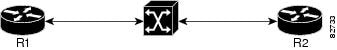
When router R1 detects the first OAM command cell from router R2, time stamp T1 is noted. When the next OAM command cell is detected, time stamp T2 is noted. The interval T1 minus T2 provides the OAM the loopback frequency of router R2. The average value of this interval is taken by measuring it a random number of times. (The interval needs to be taken a random number of times to avoid a race condition that might happen when routers R1 and R2 implement this algorithm and the frequency is the same.)
At the end of the random time period, router R1 stops sending OAM command cells and starts the OAM traffic monitoring timer. This timer in router R1 checks for a change in interval frequency in router R2. If there is a change, the traffic monitoring timer is stopped and the VC goes into Retry mode and checks whether the link is still up. In Retry mode, OAM command loopback cells are transmitted at an interval of one per second for 3 seconds. If router R1 does not receive a response to the command cell, the link is changed to the Down state.
 Note | If ATM OAM traffic reduction is enabled on routers R1 and R2, then because of the random nature of the traffic reduction algorithm, either router can initiate OAM command cells and the other router will have to listen to the incoming OAM command cells. If this feature is enabled on only one router (R1, for example), then the frequency of that router must be greater than or equal to the interval frequency set in the other router (R2) in order for router R1 to stop sending OAM command cells. The ATM OAM Traffic Reduction feature is enabled by the oam-pvc command. When the optimum keyword is enabled, and when a change in the interval frequency of router R2 is detected, the VC initiates an OAM command cell from router R1 and does not go into the Retry mode immediately. If no response is obtained, the VC goes into the Retry mode and follows the OAM Retry procedure. |
How to Configure ATM OAM Traffic Reduction
- Configuring ATM OAM Traffic Reduction on an ATM Interface
- Configuring ATM OAM Traffic Reduction on a VC Class
- Verifying ATM OAM Traffic Reduction
Configuring ATM OAM Traffic Reduction on an ATM Interface
To configure ATM OAM traffic reduction on an ATM interface, use the following commands .
1.
enable
2.
configure
terminal
3.
interface
atm
interface-number
.
subinterface-number
4.
pvc
vpi
/
vci
5.
oam-pvc
[frequency | manage [frequency [auto-detect [optimum] | keep-vc-up [seg aisrdi failure] | loop-detection]]]
6.
exit
DETAILED STEPS
Configuring ATM OAM Traffic Reduction on a VC Class
To configure ATM OAM traffic reduction on a VC class, use the following commands.
1.
enable
2.
configure
terminal
3.
vc-class
atm
vc-class-name
4.
oam-pvc
[frequency | manage [frequency [auto-detect [optimum] | loop-detection]]]
5.
exit
6.
interface
atm
interface-number
.
subinterface-number
7.
class-int
vc-class-name
8.
pvc
vpi
/
vci
9.
exit
DETAILED STEPS
Verifying ATM OAM Traffic Reduction
To verify that the ATM OAM Traffic Reduction feature is working, perform the following steps.
1.
enable
2.
show
atm
oam
auto-detect
[atm interface-number . subinterface-number]
3.
show
atm
pvc
[interface atm type number[vpi / vci | vci | word] vpi / vci | vci | word]
DETAILED STEPS
Configuration Examples for ATM OAM Traffic Reduction
- ATM OAM Traffic Reduction on an ATM Interface Example
- ATM OAM Traffic Reduction on a VC Class Example
- Verify ATM OAM Traffic Reduction Example
ATM OAM Traffic Reduction on an ATM Interface Example
The following example enables ATM OAM traffic reduction on an ATM interface:
interface ATM1/1/1.100 point-to-point
 ip address 60.1.2.1 255.255.255.0
 no atm enable-ilmi-trap
 pvc 11/111
  oam-pvc manage auto-detect optimum
  encapsulation aal5snap
ATM OAM Traffic Reduction on a VC Class Example
The following example enables ATM OAM traffic reduction using a VC class:
vc-class atm oam-tests
 oam-pvc manage auto-detect optimum
interface ATM1/1/2.100 point-to-point
 ip address 60.1.3.1 255.255.255.0
 class-int oam-tests
 no atm enable-ilmi-trap
 pvc 12/222
  encapsulation aal5snap
Verify ATM OAM Traffic Reduction Example
In the following examples, the output is displayed for each command in the task.
Sample Output for the show atm oam auto-detect Command
The following is sample output from the show atm oam auto-detect command:
Router# show atm oam auto-detect atm 1/1/2.100

ATM OAM Auto Detect statistics on ATM1/1/2
Auto Detection statistics:
ATM OAM AUTO DETECT INIT : 1
ATM OAM SENDING MONITORING : 0
ATM OAM MONITORING : 0
OAM Loopback statistics:
 DownRetry : 0
 UpRetry : 0
 Verified : 1
 Not Verified : 0
 Verified and Not Monitoring: 1
Router#
Sample Output for the show atm pvc Command
The following is sample output from the show atm pvc command with ATM OAM traffic reduction enabled:
Router# show atm pvc 12/222

ATM1/1/2.100: VCD: 1, VPI: 12, VCI: 222
UBR, PeakRate: 149760 (353208 cps)
AAL5-LLC/SNAP, etype:0x0, Flags: 0x1840, VCmode: 0x0, Encapsize: 12
OAM frequency: 10 second(s), OAM retry frequency: 1 second(s)
OAM up retry count: 3, OAM down retry count: 5
OAM Loopback status: OAM Received
Last cell looped No
Loop detect state 0, Last cell looped 0, OAM Retries 0, Loop Retries 0
OAM VC Status: Verified
OAM Auto Detect state: ATM OAM AUTO DETECT INIT
OAM PEER frequency: 0 second(s)
Additional References
Related Documents
|
Related Topic |
Document Title |
|---|---|
|
Cisco IOS commands |
|
|
ATM commands |
Cisco IOS Asynchronous Transfer Mode Command Reference |
Standards
|
Standard |
Title |
|---|---|
|
None |
-- |
MIBs
|
MIB |
MIBs Link |
|---|---|
|
None |
To locate and download MIBs for selected platforms, Cisco software releases, and feature sets, use Cisco MIB Locator found at the following URL: |
RFCs
|
RFC |
Title |
|---|---|
|
None |
-- |
Technical Assistance
|
Description |
Link |
|---|---|
|
The Cisco Support and Documentation website provides online resources to download documentation, software, and tools. Use these resources to install and configure the software and to troubleshoot and resolve technical issues with Cisco products and technologies. Access to most tools on the Cisco Support and Documentation website requires a Cisco.com user ID and password. |
Feature Information for ATM OAM Traffic Reduction
The following table provides release information about the feature or features described in this module. This table lists only the software release that introduced support for a given feature in a given software release train. Unless noted otherwise, subsequent releases of that software release train also support that feature.
Use Cisco Feature Navigator to find information about platform support and Cisco software image support. To access Cisco Feature Navigator, go to www.cisco.com/go/cfn. An account on Cisco.com is not required.
|
Feature Name |
Releases |
Feature Information |
|---|---|---|
|
ATM OAM Traffic Reduction |
Cisco IOS XE Release 2.3 |
The ATM OAM Traffic Reduction feature is a mechanism for reducing overhead when loopback cells are being used for fault detection in bidirectional virtual circuits (VCs) over ATM.. The following commands were introduced or modified: oam-pvc show atm oam auto-detect show atm pvc |