- Configuring ATM
- ATM Conditional Debug Support
- ATM OAM Ping
- ATM OAM Traffic Reduction
- Local Template-Based ATM PVC Provisioning
- ATM PVC Range
- Configuring ATM SNMP Trap and OAM Enhancements
- ATM PVC F5 OAM Recovery Traps
- ATM VP Average Traffic Rate
- ATM Hierarchical Shaping ATM VC into VP Shaping
- Autosense for ATM PVCs and MUX SNAP Encapsulation
- N:1 PVC Mapping to PWE with Nonunique VPIs
- Index
- Finding Feature Information
- Restrictions for Configuring ATM
- ATM Interface
- How to Configure ATM
- Configuring PVCs
- Creating a Permanent Virtual Circuit
- Creating a PVC on a Point-to-Point Subinterface
- Verifying a Multipoint PVC Configuration
- Mapping a Protocol Address to a PVC
- Configuring the AAL and Encapsulation Type
- Configuring PVC Traffic Parameters
- Enabling Inverse ARP
- Enabling ANCP on an ATM Interface
- Configuring Loopback Cells to Verify Connectivity
- Configuring Broadcast on a PVC
- Configuring a PVC on a Multipoint Subinterface
- Assigning a VC Class to a PVC
- Configuring PVC Trap Support
- Creating a PVC Example
- PVC with AAL5 and LLC SNAP Encapsulation Examples
- PVCs in a Fully Meshed Network Example
- Enabling Inverse ARP Example
- Enabling ANCP on ATM Interfaces Example
- Configuring Loopback Cells Example
- Configuring PVC Trap Support Example
- Creating a VC Class Example
- Applying a VC Class Example
- OAM Management on an ATM PVC Example
- Example Configuring a PVC Bundle
- PVC on a Point-to-Point Subinterface Configuration Example
Configuring ATM
This chapter describes how to configure ATM on the Cisco ASR 1000 Series Aggregation Services Routers.
- Finding Feature Information
- Restrictions for Configuring ATM
- ATM Interface
- How to Configure ATM
- ATM Configuration Examples
- Monitoring and Maintaining the ATM Interface
- Feature Information for Configuring ATM
- Additional References
Finding Feature Information
Your software release may not support all the features documented in this module. For the latest caveats and feature information, see Bug Search Tool and the release notes for your platform and software release. To find information about the features documented in this module, and to see a list of the releases in which each feature is supported, see the feature information table at the end of this module.
Use Cisco Feature Navigator to find information about platform support and Cisco software image support. To access Cisco Feature Navigator, go to www.cisco.com/go/cfn. An account on Cisco.com is not required.
Restrictions for Configuring ATM
Restrictions for PVC Bundle Management
ATM PVC Bundling Support on ASR1K
ATM Interface
Asynchronous Transfer Mode (ATM) uses one Virtual Circuit (VC) to carry all traffic to the next hop address. Even with VC multiplexing, a single VC carries all traffic of the same protocol to the next hop address. Though Weighted Random Early Discard (Per-VC (D)WRED) and WFQ can classify and prioritize the packets, they all share one single Quality of Service (QoS) VC.
Enabling the ATM Interface
This section describes how to configure an ATM interface. For the AIP, all ATM port adapters, and the 1-port ATM-25 network module, the port number is always 0. For example, the slot/port address of an ATM interface on an AIP installed in slot 1 is 1/0.
To configure the ATM interface, use the following commands beginning in privileged EXEC mode:
1. Device# configure terminal
3. Device(config-if)# ip address ip-address mask
4. Device(config-if)# no shutdown
DETAILED STEPS
VC Bundle Support and Bundle Management
ATM VC bundle management allows you to configure multiple VCs that have different QoS characteristics between any pair of ATM-connected routers. As shown in the figure below, these VCs are grouped in a bundle and are referred to as bundle members.

ATM VC bundle management allows you to define an ATM VC bundle and add VCs to it. Each VC of a bundle has its own ATM traffic class and ATM traffic parameters. You can apply attributes and characteristics to discrete VC bundle members or you can apply them collectively at the bundle level.
Using VC bundles, you can create differentiated service by flexibly distributing IP precedence levels over the different VC bundle members. You can map a single precedence level or a range of levels to each discrete VC in the bundle, thereby enabling individual VCs in the bundle to carry packets marked with different precedence levels. You can use WRED (or DWRED) to further differentiate service across traffic that has different IP precedences but that uses the same VC in a bundle.
To determine which VC in the bundle to use to forward a packet to its destination, the ATM VC bundle management software matches precedence levels between packets and VCs (see the figure below). IP traffic is sent to the next hop address for the bundle because all VCs in a bundle share the same destination, but the VC used to carry a packet depends on the value set for that packet in the IP Precedence bits of the type of service (ToS) byte of its header. The ATM VC bundle management software matches the IP precedence of the packet to the IP Precedence value or range of values assigned to a VC, sending the packet out on the appropriate VC. Moreover, the ATM VC bundle management feature allows you to configure how traffic will be redirected when the VC the packet was matched to goes down. The figure below illustrates how the ATM VC bundle management software determines which permanent virtual circuit (PVC) bundle member to use to carry a packet and how WRED (or DWRED) is used to differentiate traffic on the same VC.

The support of multiple parallel ATM VCs allows you to create stronger service differentiation at the IP layer. For instance, you might want to provide IP traffic belonging to real-time CoS (such as Voice over IP traffic) on an ATM VC with strict constraints (constant bit rate (CBR) or variable bit rate real-time (VBR-rt), for example), while transporting traffic other than real-time traffic over a more elastic ATM available bit rate (ABR) PVC. Using a configuration such as this would allow you to fully utilize your network capacity. You could also elect to transport best-effort IP traffic over an unspecified bit rate (UBR) PVC--UBR is effectively the ATM version of best-effort service.
How to Configure ATM
To configure ATM, complete the tasks in the following sections. The first task is required, and then you must configure at least one PVC or SVC. The virtual circuit options you configure must match in three places: on the router, on the ATM switch, and at the remote end of the PVC or SVC connection. The remaining tasks are optional.
- Configuring a VC Bundle
- Configuring PVCs
- Configuring VC Classes
- Configuring VC Management
- Customizing the ATM Interface
Configuring a VC Bundle
Creating a VC Bundle
|
Command |
Purpose |
|---|---|
Device(config-if)# bundle bundle-name
|
Creates the specified bundle and enters bundle configuration mode. |
Applying Parameters to Individual VCs
- Configuring a VC Bundle Member Directly
- Configuring VC Class Parameters to Apply to a VC Bundle Member
- Applying a VC Class to a Discrete VC Bundle Member
- Configuring a VC Not to Accept Bumped Traffic
- Monitoring and Maintaining VC Bundles and Their VC Members
Configuring a VC Bundle Member Directly
|
Command |
Purpose |
|---|---|
Device(config-if-atm-member)# ubr output-pcr [input-pcr] |
Configures the VC for unspecified bit rate (UBR) QoS and specifies the output peak cell rate (PCR) for it. |
Device(config-if-atm-member)# ubr+ output-pcr output-mcr [input-pcr] [input-mcr] |
Configures the VC for UBR QoS and specifies the output PCR and output minimum guaranteed cell rate for it. |
Device(config-if-atm-member)# vbr-nrt output-pcr output-scr output-mbs [input-pcr] [input-scr] [input-mbs] |
Configures the VC for variable bit rate nonreal-time (VBR-nrt) QoS and specifies the output PCR, output sustainable cell rate, and output maximum burst cell size for it. |
Device(config-if-atm-member)# precedence [other | range] |
Configures the precedence levels for the VC. |
Device(config-if-atm-member)# bump {implicit | explicit precedence-level | traffic} |
Configures the bumping rules for the VC. |
Device(config-if-atm-member)# protect {group | vc} |
Configures the VC to belong to the protected group of the bundle or to be an individually protected VC bundle member. |
Configuring VC Class Parameters to Apply to a VC Bundle Member
Applying a VC Class to a Discrete VC Bundle Member
|
Command |
Purpose |
|---|---|
Device(config-if-atm-member)# class-vc vc-class -name |
Assigns a VC class to a VC bundle member. |
Configuring a VC Not to Accept Bumped Traffic
|
Command |
Purpose |
|---|---|
Router(config-if-atm-member)# no bump traffic
|
Configures the VC not to accept any bumped traffic that would otherwise be redirected to it. |
Monitoring and Maintaining VC Bundles and Their VC Members
|
Command |
Purpose |
|---|---|
Device# show atm bundle bundle-name |
Displays the bundle attributes assigned to each bundle VC member and the current working status of the VC members. |
Device# show atm bundle bundle-name statistics [detail] |
Displays statistics or detailed statistics on the specified bundle. |
Device# show atm map
|
Displays a list of all configured ATM static maps to remote hosts on an ATM network and on ATM bundle maps. |
Device# debug atm bundle errors
|
Displays information on bundle errors. |
Device# debug atm bundle events
|
Displays a record of bundle events. |
Applying Bundle-Level Parameters
- Configuring Bundle-Level Parameters
- Configuring VC Class Parameters to Apply to a VC Bundle Member
- Attaching a Class to a Bundle
- Committing a VC to a Bundle
Configuring Bundle-Level Parameters
|
Command |
Purpose |
||
|---|---|---|---|
Device(config-atm-bundle)# protocol protocol {protocol-address | inarp} [[no] broadcast] |
Configures a static map or enables Inverse Address Resolution Protocol (Inverse ARP) or Inverse ARP broadcasts for the bundle.
|
||
Device(config-atm-bundle)# encapsulation aal-encap |
Configures the ATM adaptation layer (AAL) and encapsulation type for the bundle. |
||
Device(config-atm-bundle)# inarp minutes |
Configures the Inverse ARP time period for all VC bundle members. |
||
Device(config-atm-bundle)# broadcast
|
Enables broadcast forwarding for all VC bundle members. |
||
Device(config-atm-bundle)# oam retry up-count down-count retry frequency
|
Configures the VC bundle parameters related to operation, administration, and maintenance (OAM) management. |
||
Device(config-atm-bundle)# oam-bundle [manage] [frequency] |
Enables end-to-end F5 OAM loopback cell generation and OAM management for all VCs in the bundle. |
Configuring VC Class Parameters to Apply to a VC Bundle Member
|
Command |
Purpose |
||
|---|---|---|---|
Device(config-vc-class)# bump {implicit | explicit precedence-level | traffic} |
Specifies the bumping rules for the VC member to which the class is applied. These rules determine to which VC in the bundle traffic is directed when the carrier VC bundle member goes down.
|
||
Device(config-vc-class)# precedence precedence min-threshold max-threshold mark-probability-denominator |
Defines precedence levels for the VC member to which the class is applied. |
||
Device(config-vc-class)# protect {group | vc} |
Configures the VC as a member of the protected group of the bundle or as an individually protected VC. |
Attaching a Class to a Bundle
|
Command |
Purpose |
||
|---|---|---|---|
(config-atm-bundle)# class-bundle vc-class-name |
Configures a bundle with the bundle-level commands contained in the specified VC class.
|
Committing a VC to a Bundle
|
Command |
Purpose |
|---|---|
Device(config-atm-bundle)# pvc-bundle pvc-name [vpi/] [vci] |
Adds the specified VC to the bundle and enters bundle-vc configuration mode in order to configure the specified VC bundle member. |
Configuring PVCs
To use a permanent virtual circuit (PVC), you must configure the PVC into both the router and the ATM switch. PVCs remain active until the circuit is removed from either configuration.
When a PVC is configured, all the configuration options are passed on to the ATM interface. These PVCs are writable into the nonvolatile RAM (NVRAM) as part of the Route Processor (RP) configuration and are used when the RP image is reloaded.
Some ATM switches might have point-to-multipoint PVCs that do the equivalent of broadcasting. If a point-to-multipoint PVC exists, then that PVC can be used as the sole broadcast PVC for all multicast requests.
To configure a PVC, perform the tasks in the following sections.
- Creating a Permanent Virtual Circuit
- Creating a PVC on a Point-to-Point Subinterface
- Verifying a Multipoint PVC Configuration
- Mapping a Protocol Address to a PVC
- Configuring the AAL and Encapsulation Type
- Configuring PVC Traffic Parameters
- Enabling Inverse ARP
- Enabling ANCP on an ATM Interface
- Configuring Loopback Cells to Verify Connectivity
- Configuring Broadcast on a PVC
- Configuring a PVC on a Multipoint Subinterface
- Assigning a VC Class to a PVC
- Configuring PVC Trap Support
Creating a Permanent Virtual Circuit
To use a permanent virtual circuit (PVC), configure the PVC in both the router and the ATM switch. PVCs remain active until the circuit is removed from either configuration. To create a PVC on the ATM interface and enter interface ATM VC configuration mode, perform the following procedure beginning in global configuration mode:
1. Device(config)# interface atm slot/subslot/port.subinterface [.subinterface-number {multipoint | point-to-point}]
2. (config-if)# ipaddressaddress mask
3. Device(config-if)# atm tx-latencymilliseconds
4. Device(config-if)# pvc [name ] vpi /vci
5. Device(config-if-atm-vc)# protocol protocol {protocol-address | inarp} [[no] broadcast]
6. Device(config-if-atm-vc)# inarp minutes
7. Device(config-if-atm-vc)# encapsulation {aal5mux|aal5nlpid|aal5snap}
8. Device(config-if-atm-vc)# tx-limit buffers
9. Device(config-if-atm-vc)# end
DETAILED STEPS
| Command or Action | Purpose | |||
|---|---|---|---|---|
| Step 1 | Device(config)# interface atm slot/subslot/port.subinterface [.subinterface-number {multipoint | point-to-point}] |
Enters subinterface configuration mode for the specified port on the ATM Interface Module (IM), where:
| ||
| Step 2 | (config-if)# ipaddressaddress mask |
Assigns the specified IP address and subnet mask to the interface or subinterface. | ||
| Step 3 | Device(config-if)# atm tx-latencymilliseconds |
(Optional) Configures the default transmit latency for VCs on this ATM IM interface. The valid range for milliseconds is from 1 to 200, with a default of 100 milliseconds. | ||
| Step 4 | Device(config-if)# pvc [name ] vpi /vci |
Configures a new ATM PVC by assigning its VPI/VCI numbers and enters ATM VC configuration mode. The valid values for vpi /vci are:
| ||
| Step 5 |
Device(config-if-atm-vc)#
protocol
protocol
{protocol-address |
inarp} [[no]
broadcast]
Example:
|
Configures the PVC for a particular protocol and maps it to a specific protocol-address .
| ||
| Step 6 | Device(config-if-atm-vc)# inarp minutes |
(Optional) If using Inverse ARP, configures how often the PVC transmits Inverse ARP requests to confirm its address mapping. The valid range is 1 to 60 minutes, with a default of 15 minutes. | ||
| Step 7 | Device(config-if-atm-vc)# encapsulation {aal5mux|aal5nlpid|aal5snap} |
(Optional) Configures the ATM adaptation layer (AAL) and encapsulation type, where:
Possible values for the protocol argument are as follows:
| ||
| Step 8 | Device(config-if-atm-vc)# tx-limit buffers |
(Optional) Specifies the number of transmit buffers for this VC. The valid range is from 1 to 57343, with a default value that is based on the current VC line rate and on the latency value that is configured with the atmtx-latency command.
| ||
| Step 9 | Device(config-if-atm-vc)# end |
Exits ATM VC configuration mode and returns to privileged EXEC mode. |
Creating a PVC on a Point-to-Point Subinterface
Use point-to-point subinterfaces to provide each pair of routers with its own subnet. When you create a PVC on a point-to-point subinterface, the router assumes it is the only point-to-point PVC that is configured on the subinterface, and it forwards all IP packets with a destination IP address in the same subnet to this VC. To configure a point-to-point PVC, perform the following procedure beginning in global configuration mode:
1. Device(config)# interfaceatmslot/subslot/port.subinterfacepoint-to-point
2. Device(config-subif)# ipaddressaddress mask
3. Device(config-subif)# pvc [name ] vpi /vci
4. Device(config-if-atm-vc)# protocolprotocol protocol-address [[no] broadcast]
5. Device(config-if-atm-vc)# encapsulation{aal5muxprotocol|aal5nlpid|aal5snap}
6. Device(config-if)# end
DETAILED STEPS
| Command or Action | Purpose | |||
|---|---|---|---|---|
| Step 1 | Device(config)# interfaceatmslot/subslot/port.subinterfacepoint-to-point |
Creates the specified point-to-point subinterface on the given port on the specified ATM SPA, and enters subinterface configuration mode, where:
| ||
| Step 2 | Device(config-subif)# ipaddressaddress mask |
Assigns the specified IP address and subnet mask to this subinterface. | ||
| Step 3 | Device(config-subif)# pvc [name ] vpi /vci |
Configures a new ATM PVC by assigning its VPI/VCI numbers and enters ATM VC configuration mode. The valid values for vpi /vci are:
| ||
| Step 4 | Device(config-if-atm-vc)# protocolprotocol protocol-address [[no] broadcast] |
Configures the PVC for a particular protocol and maps it to a specific protocol-address .
The protocol command also has an inarp option, but this option is not meaningful on point-to-point PVCs that use a manually configured address. | ||
| Step 5 | Device(config-if-atm-vc)# encapsulation{aal5muxprotocol|aal5nlpid|aal5snap} |
(Optional) Configures the ATM adaptation layer (AAL) and encapsulation type, where:
| ||
| Step 6 | Device(config-if)# end |
Exits interface configuration mode and returns to privileged EXEC mode. |
To verify the configuration and current status of all PVCs on a particular interface, you can also use the
showatmvcinterfaceatm command.

Tip
Verifying a Multipoint PVC Configuration
To verify the configuration of a particular PVC, use the show atm pvc command:
Device# show atm pvc 1/120

ATM3/1/0.120: VCD: 1, VPI: 1, VCI: 120
UBR, PeakRate: 149760
AAL5-LLC/SNAP, etype:0x0, Flags: 0xC20, VCmode: 0x0
OAM frequency: 0 second(s), OAM retry frequency: 1 second(s)
OAM up retry count: 3, OAM down retry count: 5
OAM Loopback status: OAM Disabled
OAM VC status: Not Managed
ILMI VC status: Not Managed
InARP frequency: 15 minutes(s)
Transmit priority 3
InPkts: 1394964, OutPkts: 1395069, InBytes: 1833119, OutBytes: 1838799
InPRoc: 1, OutPRoc: 1, Broadcasts: 0
InFast: 0, OutFast: 0, InAS: 94964, OutAS: 95062
InPktDrops: 0,  OutPktDrops: 0
CrcErrors: 0, SarTimeOuts: 0, OverSizedSDUs: 0, LengthViolation: 0, CPIErrors: 0
Out CLP=1 Pkts: 0
OAM cells received: 0
F5 InEndloop: 0, F5 InSegloop: 0, F5 InAIS: 0, F5 InRDI: 0
F4 InEndloop: 0, F4 InSegloop: 0, F4 InAIS: 0, F4 InRDI: 0
OAM cells sent: 0
F5 OutEndloop: 0, F5 OutSegloop: 0, F5 OutRDI: 0
F4 OutEndloop: 0, F4 OutSegloop: 0, F4 OutRDI: 0
OAM cell drops: 0
Status: UP
 Note | To verify the configuration and current status of all PVCs on a particular interface, you can also use the show atm vc interface command. |
Mapping a Protocol Address to a PVC
The ATM interface supports a static mapping scheme that identifies the network address of remote hosts or routers. This section describes how to map a PVC to an address, which is a required task for configuring a PVC.
Note | If you enable or disable broadcasting directly on a PVC using the protocol command, this configuration will take precedence over any direct configuration using the broadcast command. |
See examples of PVC configurations in the section "ATM Configuration Examples".
To map a protocol address to a PVC, use the following command in interface-ATM-VC configuration mode:
|
Command |
Purpose |
|---|---|
Router(config-if-atm-vc)# protocol protocol protocol-address [[no] broadcast] |
Maps a protocol address to a PVC. |
Configuring the AAL and Encapsulation Type
To configure the ATM adaptation layer (AAL) and encapsulation type, use the following command beginning in interface-ATM-VC configuration mode:
|
Command |
Purpose |
|---|---|
Router(config-if-atm-vc)# encapsulation aal5 encap |
Configures the ATM adaptation layer (AAL) and encapsulation type.
|
Configuring PVC Traffic Parameters
The supported traffic parameters are part of the following service categories: Constant Bit Rate (CBR), Unspecified Bit Rate (UBR), Variable Bit Rate Non Real-Time (VBR-NRT), and real-time Variable Bit Rate (VBR). Only one of these categories can be specified per PVC connection so if a new one is entered, it will replace the existing one.
Note | The commands in this section are not supported on the ATM port adapter (PA-A1 series). The 1-port ATM-25 network module only supports UBR. |
The -pcr and -mcr arguments are the peak cell rate and minimum cell rate, respectively. The -scr and -mbs arguments are the sustainable cell rate and maximum burst size, respectively.
For a description of how to configure traffic parameters in a VC class and apply the VC class to an ATM interface or subinterface, refer to the section "Configuring VC Classes."
To configure PVC traffic parameters, use one of the following commands beginning in interface-ATM-VC configuration mode:
|
Command |
Purpose |
|---|---|
Router(config-if-atm-vc)# cbr peak_cell_rate_KBPS |
Configures the Constant Bit Rate (CBR). |
Router(config-if-atm-vc)# ubr output-pcr |
Configures the Unspecified Bit Rate (UBR). |
Router(config-if-atm-vc)# vbr-nrt output-pcr output-scr output-mbs |
Configures the Variable Bit Rate-Non Real Time (VBR-NRT) QOS. |
Router(config-if-atm-vc)# vbr-rt peak-rate average-rate burst
|
Configures the real-time Variable Bit Rate (VBR). (Cisco MC3810 and Multiport T1/E1 ATM Network Module only.) |
Enabling Inverse ARP
Inverse ARP is enabled by default when you create a PVC using the pvc command. Once configured, a protocol mapping between an ATM PVC and a network address is learned dynamically as a result of the exchange of ATM Inverse ARP packets.
Inverse ARP is supported on PVCs running IP or IPX and no static map is configured. If a static map is configured, Inverse ARP will be disabled.
When PVC discovery is enabled on an active PVC and the router terminates that PVC, the PVC will generate an ATM Inverse ARP request. This allows the PVC to resolve its own network addresses without configuring a static map.
Address mappings learned through Inverse ARP are aged out. However, mappings are refreshed periodically. This period is configurable using the inarp command, which has a default of 15 minutes.
You can also enable Inverse ARP using the protocol command. This is necessary only if you disabled Inverse ARP using the no protocol command. For more information about this command, refer to the "ATM Commands" chapter in the Cisco IOS Wide-Area Networking Command Reference.
For an example of configuring Inverse ARP, see the section "Enabling Inverse ARP Example".
To enable Inverse ARP on an ATM PVC, use the following commands beginning in global configuration mode:
- Router(config)# interface atm slot /0[. subinterface-number {multipoint | point-to-point}]
- Router(config)# interface atm slot / port-adapter /0[. subinterface-number{multipoint | point-to-point}]
1.
Do one of the following:
2. Router(config-if)# pvc [name] vpi / vci
3. Router(config-if-atm-vc)# encapsulation aal5snap
4. Router(config-if-atm-vc)# inarp minutes
DETAILED STEPS
| Command or Action | Purpose | |
|---|---|---|
| Step 1 | Do one of the following:
Example: Example:
Example: Router(config)# interface atm number[. subinterface-number {multipoint | point-to-point}] |
Specifies the ATM interface using the appropriate format of the interface atm command.1 |
| Step 2 | Router(config-if)# pvc [name] vpi / vci |
Specifies an ATM PVC by name (optional) and VPI/VCI numbers. |
| Step 3 | Router(config-if-atm-vc)# encapsulation aal5snap |
Configures AAL5 LLC-SNAP encapsulation if it is not already configured. |
| Step 4 | Router(config-if-atm-vc)# inarp minutes |
(Optional) Adjusts the Inverse ARP time period. |
Enabling ANCP on an ATM Interface
The ancp enable command should be configured only for the control VCs on which the Access Node Control Protocol (ANCP) message is sent from the DSLAM. Use the following procedure to enable ANCP on ATM interfaces. For an example of enabling ANCP, see the section Enabling ANCP on ATM Interfaces Example.
1.
enable
2.
configure
terminal
3.
ancp
adjacency
timer
interval
4.
interface
atm
slot
/
subslot
/
port
.
subinterface
5.
ip
address
ip-address
mask
6.
pvc
vpi
/
vci
7.
ancp
enable
8.
exit
DETAILED STEPS
| Command or Action | Purpose | |
|---|---|---|
| Step 1 |
enable
Example:
Router> enable
|
Enables privileged EXEC mode.
|
| Step 2 |
configure
terminal
Example:
Router# configure terminal
|
Enters global configuration mode. |
| Step 3 |
ancp
adjacency
timer
interval
Example:
Router(config)# ancp adjacency timer 100
|
Sets the ANCP adjacency timer interval, which specifies the amount of time to wait before sending an ANCP hello packet to the DSLAM.
|
| Step 4 |
interface
atm
slot
/
subslot
/
port
.
subinterface
Example:
Router(config)# interface atm 2/0/1.1
|
Creates or modifies a subinterface and enters subinterface configuration mode. |
| Step 5 |
ip
address
ip-address
mask
Example:
Router(config-subif)# ip address 10.16.1.2 255.255.0.0
|
Assigns an IP address and subnet mask to the subinterface. |
| Step 6 |
pvc
vpi
/
vci
Example:
Router(config-subif)# pvc 2/100
|
Enables an ANCP connection over ATM PVC and enters ATM virtual circuit configuration mode. |
| Step 7 |
ancp
enable
Example:
Router(config-if-atm-vc)# ancp enable
|
Enables ANCP on the interface where IP is configured. |
| Step 8 |
exit
Example:
Router(config-if-atm-vc)# exit
|
Exits ATM virtual circuit configuration mode. |
Configuring Loopback Cells to Verify Connectivity
You can optionally configure the PVC to generate end-to-end F5 OAM loopback cells to verify connectivity on the virtual circuit. The remote end must respond by echoing back such cells. If OAM response cells are missed (indicating the lack of connectivity), the PVC state goes down. If all the PVCs on a subinterface go down, the subinterface goes down.
For information about managing PVCs using OAM, see the section "Configuring OAM Management for PVCs".
For an example of OAM loopback cell generation, see the section "Configuring Loopback Cells Example".
To configure transmission of end-to-end F5 OAM cells on a PVC, use the following commands in interface-ATM-VC configuration mode:
1. Router(config-if-atm-vc)# oam-pvc [manage] frequency
2. Router(config-if-atm-vc)# oam retry up-count down-count retry-frequency
DETAILED STEPS
| Command or Action | Purpose | |
|---|---|---|
| Step 1 | Router(config-if-atm-vc)# oam-pvc [manage] frequency |
Configures transmission of end-to-end F5 OAM loopback cells on a PVC, specifies how often loopback cells should be sent, and optionally enables OAM management of the connection. |
| Step 2 | Router(config-if-atm-vc)# oam retry up-count down-count retry-frequency |
(Optional) Specifies OAM management parameters for verifying connectivity of a PVC connection. This command is only supported if OAM management is enabled.
|
Configuring Broadcast on a PVC
To send duplicate broadcast packets for all protocols configured on a PVC, use the following command in interface-ATM-VC configuration mode:
Note | If you enable or disable broadcasting directly on a PVC using the protocol command, this configuration will take precedence over any direct configuration using the broadcast command. |
|
Command |
Purpose |
|---|---|
Router(config-if-atm-vc)# broadcast
|
Sends duplicate broadcast packets for all protocols configured on a PVC. |
Configuring a PVC on a Multipoint Subinterface
Creating a multipoint subinterface allows you to create a point-to-multipoint PVC that can be used as a broadcast PVC for all multicast requests. To create a PVC on a multipoint subinterface, use the following procedure beginning in global configuration mode:
1. Router(config)# interface atm slot/subslot/port.subinterface multipoint
2. Router(config-subif)# ip address address mask
3. Router(config-subif)# no ip directed-broadcast
4. Router(config-subif)# pvc [name ] vpi /vci
5. Router(config-if-atm-vc)# protocol protocol {protocol-address | inarp} broadcast
6. Router(config-if-atm-vc)# inarp minutes
7. Router(config-if-atm-vc)# encapsulation{aal5muxprotocol|aal5nlpidaal5snap}
8. Router(config-if-atm-vc)# end
DETAILED STEPS
| Command or Action | Purpose | |||
|---|---|---|---|---|
| Step 1 | Router(config)# interface atm slot/subslot/port.subinterface multipoint |
Creates the specified point-to-multipoint subinterface on the given port on the specified ATM SPA, and enters subinterface configuration mode, where:
| ||
| Step 2 | Router(config-subif)# ip address address mask |
Assigns the specified IP address and subnet mask to this subinterface. | ||
| Step 3 | Router(config-subif)# no ip directed-broadcast |
(Optional) Disables the forwarding of IP directed broadcasts, which are sometimes used in denial of service (DOS) attacks. | ||
| Step 4 | Router(config-subif)# pvc [name ] vpi /vci |
Configures a new ATM PVC by assigning its VPI/VCI numbers and enters ATM VC configuration mode. The valid values for vpi /vci are:
| ||
| Step 5 | Router(config-if-atm-vc)# protocol protocol {protocol-address | inarp} broadcast |
Configures the PVC for a particular protocol and maps it to a specific protocol-address .
| ||
| Step 6 | Router(config-if-atm-vc)# inarp minutes |
(Optional) If using Inverse ARP, configures how often the PVC transmits Inverse ARP requests to confirm its address mapping. The valid range is 1 to 60 minutes, with a default of 15 minutes. | ||
| Step 7 | Router(config-if-atm-vc)# encapsulation{aal5muxprotocol|aal5nlpidaal5snap} |
(Optional) Configures the ATM adaptation layer (AAL) and encapsulation type, where:
| ||
| Step 8 | Router(config-if-atm-vc)# end |
Exits interface configuration mode and returns to privileged EXEC mode. |
Assigning a VC Class to a PVC
By creating a VC class, you can preconfigure a set of default parameters that you may apply to a PVC. To create a VC class, refer to the section "Configuring VC Classes".
Once you have created a VC class, use the following command in interface-ATM-VC configuration mode to apply the VC class to a PVC:
|
Command |
Purpose |
|---|---|
Router(config-if-atm-vc)# class-vc vc-class-name |
Applies a VC class to a PVC.
|
Configuring PVC Trap Support
You can configure the PVC to provide failure notification by sending a trap when a PVC on an ATM interface fails or leaves the UP operational state.
PVC Failure Notification
Only one trap is generated per hardware interface, within the specified interval defined by the interval "atmIntPvcNotificationInterval". If other PVCs on the same interface go DOWN during this interval, traps are generated and held until the interval has elapsed. Once the interval has elapsed, the traps are sent if the PVCs are still DOWN.
No trap is generated when a PVC returns to the UP state after having been in the DOWN state. If you need to detect the recovery of PVCs, you must use the SNMP management application to regularly poll your router.
PVC Status Tables
When PVC trap support is enabled, the SNMP manager can poll the SNMP agent to get PCV status information. The table "atmInterfaceExtTable" provides PVC status on an ATM interface. The table "atmCurrentlyFailingPVclTable" provides currently failing and previously failed PVC time-stamp information.
Note | PVC traps are only supported on permanent virtual circuit links (PVCLs), not permanent virtual path links (PVPLs). |
Prerequisites
Before you enable PVC trap support, you must configure SNMP support and an IP routing protocol on your router. See the "ATM Configuration Examples" section.
For more information about configuring SNMP support, refer to the chapter "Configuring SNMP Support" in the Cisco IOS Configuration Fundamentals Configuration Guide.
For information about configuring IP routing protocols, refer to the Cisco IOS IP Routing Protocols Configuration Guide.
To receive PVC failure notification and access to PVC status tables on your router, you must have the Cisco PVC trap MIB called CISCO-IETF-ATM2-PVCTRAP-MIB.my compiled in your NMS application. You can find this MIB on the Web at Cisco’s MIB websiteat the URL: http://www.cisco.com/public/sw-center/netmgmt/cmtk/mibs.shtml.
Enabling PVC Trap Support
When you configure PVC trap support, you must also enable OAM management on the PVC.
For more information on OAM management, see the section "Configuring OAM Management for PVCs" later in this chapter.
The new objects in this feature are defined in the IETF draft The Definitions of Managed Objects for ATM Management , which is an extension to the AToM MIB (RFC 1695).
For an example of configuring PVC trap support, see the section "Configuring PVC Trap Support Example".
To enable PVC trap support and OAM management, use the following commands beginning in global configuration mode:
1. Router(config)# snmp-server enable traps atm pvc interval secondsfail-interval seconds
3. Router(config-if)# pvc [name] vpi / vci
4. Router(config-if-atm-vc)# oam-pvc manage
DETAILED STEPS
| Command or Action | Purpose | |
|---|---|---|
| Step 1 | Router(config)# snmp-server enable traps atm pvc interval secondsfail-interval seconds |
Enables PVC trap support. |
| Step 2 | Do one of the following:
Example: Router(config)# interface atm number[. subinterface-number {multipoint | point-to-point}] |
Specifies the ATM interface using the appropriate form of the interface atm command.2 |
| Step 3 | Router(config-if)# pvc [name] vpi / vci |
Enables the PVC. |
| Step 4 | Router(config-if-atm-vc)# oam-pvc manage |
Enables end-to-end OAM management for an ATM PVC. |
Configuring VC Classes
A VC class is a set of preconfigured VC parameters that you configure and apply to a particular VC or ATM interface. You may apply a VC class to an ATM main interface, subinterface, or PVC. For example, you can create a VC class that contains VC parameter configurations that you will apply to a particular PVC. You might create another VC class that contains VC parameter configurations that you will apply to all VCs configured on a particular ATM main interface or subinterface. Refer to the "ATM Configuration Examples" section for examples of VC class configurations.
- Creating a VC Class
- Configuring VC Parameters
- Applying a VC Class on an ATM PVC
- Applying a VC Class on an ATM Interface
Creating a VC Class
To create a VC class, use the following command in global configuration mode:
For examples of creating VC classes, see the section "Creating a VC Class Example".
|
Command |
Purpose |
|---|---|
Router(config)# vc-class atm name |
Creates a VC class and enters vc-class configuration mode. |
Configuring VC Parameters
After you create a VC class and enter vc-class configuration mode, configure VC parameters using one or more of the following commands:
- broadcast
- cbr
- encapsulation aal5
- idle-timeout
- inarp
- oam-pvc
- oam retry
- protocol
- ubr
- vbr-nrt
Refer to the sections "Configuring PVCs" and "Configuring PVC Trap Support" for descriptions of how to configure these commands for PVCs.
For examples of creating VC classes, see the section "Creating a VC Class Example".
Applying a VC Class on an ATM PVC
Once you have created and configured a VC class, you can apply it directly on an ATM PVC, or you can apply it on an ATM interface or subinterface.
To apply a VC class directly on an ATM PVC use the following commands beginning in interface configuration mode:
1. Router(config-if)# pvc [name] vpi / vci
2. Router(config-if-atm-vc)# class-vcvc-class-name
DETAILED STEPS
| Command or Action | Purpose |
|---|
Applying a VC Class on an ATM Interface
To apply a VC class on an ATM main interface or subinterface, use the following commands beginning in global configuration mode:
- Router(config)# interface atm slot /0[. subinterface-number {multipoint | point-to-point}]
- Router(config)# interface atm slot / port-adapter /0[. subinterface-number {multipoint | point-to-point}]
1.
Do one of the following:
2. Router(config-if)# class-int vc-class-name
DETAILED STEPS
| Command or Action | Purpose | |
|---|---|---|
| Step 1 | Do one of the following:
Example: Example:
Example: Router(config)# interface atm number[. subinterface-number {multipoint | point-to-point}] |
Specifies the ATM interface using the appropriate format of the interface atm command.3 |
| Step 2 | Router(config-if)# class-int vc-class-name |
Applies a VC class on an the ATM main interface or subinterface. |
Configuring VC Management
When you configure VC management, you enable the router to detect VC connections and disconnections automatically. This notifies protocols to reroute packets immediately, preventing protocols from waiting for unpredictable and relatively long timeout periods.
You may use operation, administration, and maintenance (OAM) to manage your PVCs, and decide which method is reliable in your particular network.
When a PVC goes down, route caches for protocols configured on that PVC are cleared (or flushed) so that new routes may be learned. The route cache flush is applied on the PVC’s interface. When all PVCs on a subinterface go down, VC management shuts down the subinterface in addition to flushing route caches. ATM hardware must keep the PVC active, however, so that OAM cells may flow. When any PVC on a subinterface comes up, the subinterface is brought up.
VC management using OAM is referred to as OAM management.
Configuring OAM Management for PVCs
OAM management may be enabled for PVCs.
By default, end-to-end F5 OAM loopback cell generation is turned off for each PVC. A PVC is determined as down when any of the following is true on that PVC:
- The router does not receive a loopback reply after a configured number of retries of sending end-to-end F5 OAM loopback cells.
- The router receives a Virtual Circuit-Alarm Indication Signals (VC-AIS) cell.
- The router receives a Virtual Circuit-Remote Detect Indicator (VC-RDI) cell.
A PVC is determined as up when all of the following are true on that PVC:
- The router receives a configured number of successive end-to-end F5 OAM loopback cell replies.
- The router does not receive VC-AIS cell for 3 seconds.
- The router does not receive VC-RDI cell for 3 seconds.
To configure OAM management for an ATM PVC, use the following commands beginning in global configuration mode:
- Router(config)# interface atm slot /0[. subinterface-number {multipoint | point-to-point}]
- Router(config)# interface atm slot / port-adapter /0[. subinterface-number {multipoint | point-to-point}]
1.
Do one of the following:
2. Router(config-if)# pvc [name] vpi / vci
3. Router(config-if-atm-vc)# oam-pvc manage [frequency]
4. Router(config-if-atm-vc)# oam retry up-count down-count retry-frequency
DETAILED STEPS
| Command or Action | Purpose | |
|---|---|---|
| Step 1 | Do one of the following:
Example: Example:
Example: Router(config)# Router(config)# interface atm number[. subinterface-number {multipoint | point-to-point}] |
Specifies the ATM interface using the appropriate format of the interface atm command.4 |
| Step 2 | Router(config-if)# pvc [name] vpi / vci |
Specifies the ATM PVC. |
| Step 3 | Router(config-if-atm-vc)# oam-pvc manage [frequency] |
Enables OAM management on the PVC. |
| Step 4 | Router(config-if-atm-vc)# oam retry up-count down-count retry-frequency |
(Optional) Specifies OAM management parameters for re-establishing and removing a PVC connection.
|
Configuring Classical IP and Inverse ARP in a PVC Environment
The ATM Inverse ARP mechanism is applicable to networks that use PVCs, where connections are established but the network addresses of the remote ends are not known. A server function is not used in this mode of operation.
By default, Inverse ARP datagrams will be sent on this virtual circuit every 15 minutes. To adjust the Inverse ARP time period, use the inarp minutes command in interface-ATM-VC configuration mode.
Note | The ATM ARP mechanism works with IP only. The Inverse ATM ARP mechanism works with IP and IPX only. For all other protocols, the destination address must be specified. |
In a PVC environment, the ATM Inverse ARP mechanism is enabled by default for IP and IPX when you use the following commands beginning in global configuration mode:
- Router(config)# interface atm slot /0
- Router(config)# interface atm slot / port-adapter /0
1.
Do one of the following:
2. Router(config-if)# ip address address mask
3. Router(config-if)# pvc [name] vpi / vci
4. Router(config-if-atm-vc)# no shutdown
5.
DETAILED STEPS
| Command or Action | Purpose | |
|---|---|---|
| Step 1 | Do one of the following:
Example: Example:
Example: Router(config)# interface atm number |
Specifies the ATM interface using the appropriate format of the interface atm command.5 |
| Step 2 | Router(config-if)# ip address address mask |
Specifies the IP address of the interface. |
| Step 3 | Router(config-if)# pvc [name] vpi / vci |
Creates a PVC. |
| Step 4 | Router(config-if-atm-vc)# no shutdown |
Enables the ATM interface. |
| Step 5 |
|
Repeat Step 3 for each PVC you want to create. |
Customizing the ATM Interface
You can customize the ATM interface. The features you can customize have default values that will most likely suit your environment and probably need not be changed. However, you might need to enter configuration commands, depending upon the requirements for your system configuration and the protocols you plan to route on the interface.
Configuring MTU Size
Each interface has a default maximum packet size or maximum transmission unit (MTU) size. For ATM interfaces, this number defaults to 4470 bytes. The MTU can be set on a per-sub-interface basis as long as the interface MTU is as large or larger than the largest subinterface MTU.
To set the maximum MTU size, use the following command in interface configuration mode:
|
Command |
Purpose |
|---|---|
Router(config-if)# mtu bytes |
Sets the maximum MTU size. |
ATM Configuration Examples
The examples in the following sections illustrate how to configure ATM for the features described in this chapter. The examples below are presented in the same order as the corresponding configuration task sections:
- Creating a PVC Example
- PVC with AAL5 and LLC SNAP Encapsulation Examples
- PVCs in a Fully Meshed Network Example
- Enabling Inverse ARP Example
- Enabling ANCP on ATM Interfaces Example
- Configuring Loopback Cells Example
- Configuring PVC Trap Support Example
- Creating a VC Class Example
- Applying a VC Class Example
- OAM Management on an ATM PVC Example
- Example Configuring a PVC Bundle
- PVC on a Point-to-Point Subinterface Configuration Example
Creating a PVC Example
The following example shows how to create a PVC on an ATM main interface with AAL5/MUX encapsulation configured and a VBR-NRT QOS specified. For further information, refer to sections “Creating a PVC” and “Configuring PVC Traffic Parameters”.
interface 2/0
 pvc cisco 1/40
 encapsulation aal5mux ip
 vbr-nrt 100000 50000 20
 exit
PVC with AAL5 and LLC SNAP Encapsulation Examples
The following example shows how to create a PVC 0/50 on ATM interface 3/0. It uses the global default LLC/SNAP encapsulation over AAL5. The interface is at IP address 1.1.1.1 with 1.1.1.5 at the other end of the connection. For further information, refer to the sections “Creating a PVC” and “Mapping a Protocol Address to a PVC".
interface atm 3/0
 ip address 1.1.1.1 255.255.255.0
 pvc 0/50
 protocol ip 1.1.1.5 broadcast
 exit
!
 ip route-cache cbus
The following example is a typical ATM configuration for a PVC:
interface atm 4/0
 ip address 172.21.168.112 255.255.255.0
 atm maxvc 512
 pvc 1/51
 protocol ip 171.21.168.110
 exit
!
 pvc 2/52
 protocol decnet 10.1 broadcast
 exit
!
 pvc 3/53
 protocol clns 47.004.001.0000.0c00.6e26.00 broadcast
 exit
!
 decnet cost 1
 clns router iso-igrp comet
 exit
!
router iso-igrp comet
 net 47.0004.0001.0000.0c00.6666.00
 exit
!
router igrp 109
 network 172.21.0.0
 exit
!
ip domain-name CISCO.COM
PVCs in a Fully Meshed Network Example
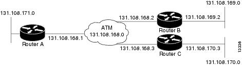
The figure below illustrates a fully meshed network. The configurations for routers A, B, and C follow the figure. In this example, the routers are configured to use PVCs. Fully meshed indicates that any workstation can communicate with any other workstation. Note that the two protocol statements configured in router A identify the ATM addresses of routers B and C. The two protocolstatements in router B identify the ATM addresses of routers A and C. The two protocol statements in router C identify the ATM addresses of routers A and B. For further information, refer to the sections “Creating a PVC” and “Mapping a Protocol Address to a PVC”.
Router A
ip routing
!
interface atm 4/0
 ip address 131.108.168.1 255.255.255.0
 pvc 0/32
 protocol ip 131.108.168.2 broadcast
 exit
!
 pvc 0/33
 protocol ip 131.108.168.3 broadcast
 exit
Router B
ip routing
!
interface atm 2/0
 ip address 131.108.168.2 255.255.255.0
 pvc test-b-1 0/32
 protocol ip 131.108.168.1 broadcast
 exit
!
 pvc test-b-2 0/34
 protocol ip 131.108.168.3 broadcast
 exit
Router C
ip routing
!
interface atm 4/0
 ip address 131.108.168.3 255.255.255.0
 pvc 0/33
 protocol ip 131.108.168.1 broadcast
 exit
!
 pvc 0/34
 protocol ip 131.108.168.2 broadcast
 exit
Enabling Inverse ARP Example
The following example shows how to enable Inverse ARP on an ATM interface and specifies an Inverse ARP time period of 10 minutes. For further information, refer to the section "Enabling Inverse ARP".
interface atm 2/0
 pvc 1/32
 inarp 10
 exit
Enabling ANCP on ATM Interfaces Example
The following example shows how to enable ANCP on an ATM subinterface. In the example, ANCP is enabled on ATM subinterface 2/0/1.1.
interface ATM2/0/0.1 point-to-point
      description ANCP Link to one DSLAM
      no ip mroute-cache
      ip address 192.168.0.2 255.255.255.252
      pvc 254/32
        protocol ip 192.168.0.1
        ancp enable
        no snmp trap link-status
Configuring Loopback Cells Example
The following example shows how to enable OAM management on an ATM PVC. The PVC is assigned the name routerA and the VPI and VCI are 0 and 32, respectively. OAM management is enabled with a frequency of 3 seconds between OAM cell transmissions. For further information, refer to the section "Enabling ANCP on an ATM Interface".
interface atm 2/0
 pvc routerA 0/32
 oam-pvc manage 3
 oam retry 5 5 10
Configuring PVC Trap Support Example
The following example shows how to configure PVC trap support on your Cisco router:
!For PVC trap support to work on your router, you must first have SNMP support and
!an IP routing protocol configured on your router:
Router(config)# snmp-server community public ro
Router(config)# snmp-server host 171.69.61.90 public

Router(config)# ip routing
Router(config)# router igrp 109
Router(config-router)# network 172.21.0.0
!
!Enable PVC trap support and OAM management:
Router(config)# snmp-server enable traps atm pvc interval 40 fail-interval 10
Router(config)# interface atm 1/0.1
Router(config-if)# pvc 0/1
Router(config-if-atm-vc)# oam-pvc manage
!
! Now if PVC 0/1 goes down, host 171.69.61.90 will receive traps.
For further information, refer to the "Configuring PVC Trap Support" section.
Creating a VC Class Example
The following example shows how to create a VC class named main and how to configure UBR and encapsulation parameters. For further information, refer to the sections "Creating a VC Class" and "Configuring VC Parameters".
vc-class atm main
 ubr 10000
 encapsulation aal5mux ip
The following example shows how to create a VC class named sub and how to configure UBR and PVC management parameters. For further information, refer to the sections "Creating a VC Class" and "Configuring VC Parameters".
vc-class atm sub
 ubr 15000
 oam-pvc manage 3
The following example shows how to create a VC class named pvc and how to configure VBR-NRT and encapsulation parameters. For further information, refer to the sections "Creating a VC Class" and "Configuring VC Parameters".
vc-class atm pvc
 vbr-nrt 10000 5000 64
 encapsulation aal5snap
Applying a VC Class Example
The following example shows how to apply the VC class named main to the ATM main interface 4/0. For further information, refer to the section "Applying a VC Class on an ATM PVC".
interface atm 4/0
 class-int main
 exit
The following example shows how to apply the VC class named sub to the ATM subinterface 4/0.5:
interface atm 4/0.5 multipoint
 class-int sub
 exit
The following example shows how to apply the VC class named pvc directly on the PVC 0/56:
interface atm 4/0.5 multipoint
 pvc 0/56
 class-vc pvc
 exit
OAM Management on an ATM PVC Example
The following example shows how to enable OAM management on an ATM PVC. The PVC is assigned the name routerA and the VPI and VCI are 0 and 32, respectively. OAM management is enabled with a frequency of 3 seconds between OAM cell transmissions. For further information, refer to the section "Configuring OAM Management for PVCs".
interface atm 2/0
 pvc routerA 0/32
 oam-pvc manage 3
 oam retry 5 5 10
!
interface atm 4/0.1 point-to-point
 pvc 0/35
 exit
No map-group and map-list commands are needed for IP.
interface atm 4/0
 ip address 1.1.1.1 255.0.0.0
 pvc 1/33
 pvc 1/34
 pvc 1/35
 bridge-group 1
!
bridge 1 protocol dec
Example Configuring a PVC Bundle
Device1:
interface ATM0/0/0.1 point-to-point
ip address 10.0.0.1 255.255.255.0
bundle test
  encapsulation aal5snap
  oam-bundle manage
  pvc-bundle 0/32
   vbr-rt 19000 15000 5000
   precedence 7
  pvc-bundle 1/33
   ubr 2480
   precedence 6
  pvc-bundle 1/34
   ubr 4890
   precedence 3-5
  pvc-bundle 1/35
!
Device2:

interface ATM0/1/0.1 point-to-point
ip address 10.0.0.2 255.255.255.0
bundle test
  encapsulation aal5snap
  oam-bundle manage
  pvc-bundle 0/32
   vbr-rt 19000 15000 5000
   precedence 7
  pvc-bundle 1/33
   ubr 2480
   precedence 6
  pvc-bundle 1/34
   ubr 4890
   precedence 3-5
  pvc-bundle 1/35
!
PVC on a Point-to-Point Subinterface Configuration Example
interface ATM5/0/0.9 point-to-point
 mtu 4474
 bandwidth 34000
 ip vrf forwarding vrfexample
 ip address 192.0.2.1 255.255.255.0
 ip mtu 4470
 pvc 11/105
  ubr 38
  oam-pvc manage
  encapsulation aal5snap
 !
interface ATM5/0/0.11 point-to-point
 mtu 4474
 bandwidth 7000
 ip address 192.0.2.2 255.255.255.0
 ip mtu 4470
 pvc 100/50
  cbr 7000
  encapsulation aal5snap
  service-policy input Leased_Line_Ingress
  max-reserved-bandwidth 100
Monitoring and Maintaining the ATM Interface
After configuring an ATM interface, you can display its status. You can also display the current state of the ATM network and connected virtual circuits. To show current virtual circuits and traffic information, use the following commands in EXEC mode:
|
Command |
Purpose |
||
|---|---|---|---|
Router# show arp
|
Displays entries in the ARP table. |
||
Router# show atm class-links {vpi / vci | name} |
Displays PVC parameter configurations and where the parameter values are inherited from. |
||
Router# show atm interface atm slot /0 Router# show atm interface atm slot / port-adapter /0 Router# show atm interface atm number |
Displays ATM-specific information about the ATM interface using the appropriate format of the show atm interface atm command.6 |
||
Router# show atm map
|
Displays the list of all configured ATM static maps to remote hosts on an ATM network. |
||
Router# show atm pvc [vpi / vci | name | interface atm interface_number] |
Displays all active ATM PVCs and traffic information. |
||
Router# show atm traffic
|
Displays global traffic information to and from all ATM networks connected to the router, OAM statistics, and a list of counters of all ATM traffic on this router. |
||
Router# show atm vc [vcd-number | [range lower-limit-vcd upper-limit-vcd] [interface ATM interface-number] [detail [prefix {vpi/vci | vcd | interface | vc_name}]] [connection-name] | signalling [freed-svcs | [cast-type {p2mp | p2p}] [detail] [interface ATM interface-number]] | summary ATM interface-number] |
Displays all active ATM virtual circuits (PVCs ) and traffic information.
|
||
Router# show interfaces atm controller.port-channels.subinterface
|
Displays statistics for the ATM interface using the appropriate format of the show interfaces atm command. |
||
Router# show network-clocks
|
Displays the clock signal sources and priorities that you established on the router. |
Feature Information for Configuring ATM
The following table provides release information about the feature or features described in this module. This table lists only the software release that introduced support for a given feature in a given software release train. Unless noted otherwise, subsequent releases of that software release train also support that feature.
Use Cisco Feature Navigator to find information about platform support and Cisco software image support. To access Cisco Feature Navigator, go to www.cisco.com/go/cfn. An account on Cisco.com is not required.
Feature Name |
Releases |
Feature Information |
|---|---|---|
|
Configuring ATM, ATM Sub-interface Multipoint |
Cisco IOS Release 2.5.0 |
ANCP needs to be enabled on ATM interface when message is sent from the DSLAM. The following commands were introduced or modified: pvc, protocol, cbr, ubr, encapsulation aal5snap, interface atm, ip address, inarp, oam-pvc manage, oam-retry, class-vc, snmp-server enable traps, vc-class atm, class-int, mtu, show atm class-links, show atm interface atm, show atm map, show atm pvc, show atm traffic, show atm vc, show network-clocks, ancp enable, ancp neighbor. |
|
IP Multicast over ATM PVC Bundle |
Cisco IOS Release XE 3.7S |
ATM VC bundle management allows you to configure multiple VCs that have different QoS characteristics between any pair of ATM-connected devices. No new commands were introduced or modified. |
Additional References
Related Documents
|
Related Topic |
Document Title |
|---|---|
|
Cisco IOS commands |
|
|
ATM commands |
Cisco IOS Asynchronous Transfer Mode Command Reference |
|
ATM SPAs |
"Overview of ATM SPAs" in the Cisco ASR 1000 Series Aggregation Services Routers SIP and SPA Software Configuration Guide |
|
Configuring IP to ATM class of service (CoS) |
|
|
Configuring PPP over Ethernet (PPPoE) over ATM |
Standards
|
Standard |
Title |
|---|---|
|
No new or modified standards are supported by this feature, and support for existing standards has not been modified by this feature. |
-- |
MIBs
|
MIB |
MIBs Link |
|---|---|
|
|
To locate and download MIBs for selected platforms, Cisco IOS XE software releases, and feature sets, use Cisco MIB Locator found at the following URL: |
RFCs
|
RFC |
Title |
|---|---|
|
No new or modified RFCs are supported by this feature, and support for existing RFCs has not been modified by this feature. |
-- |
Technical Assistance
|
Description |
Link |
|---|---|
|
The Cisco Support website provides extensive online resources, including documentation and tools for troubleshooting and resolving technical issues with Cisco products and technologies. To receive security and technical information about your products, you can subscribe to various services, such as the Product Alert Tool (accessed from Field Notices), the Cisco Technical Services Newsletter, and Really Simple Syndication (RSS) Feeds. Access to most tools on the Cisco Support website requires a Cisco.com user ID and password. |
 Feedback