Configuring Content Switching
This chapter describes how to configure content switching and contains these sections:
•![]() Configuring the Single Subnet (Bridge) Mode
Configuring the Single Subnet (Bridge) Mode
•![]() Configuring the Secure (Router) Mode
Configuring the Secure (Router) Mode

Note ![]() All examples assume that the ip slb mode csm command has been entered as described in Chapter 3, "Configuring the Content Switching Module."
All examples assume that the ip slb mode csm command has been entered as described in Chapter 3, "Configuring the Content Switching Module."
Configuring the Single Subnet (Bridge) Mode
In the single subnet (bridge) mode configuration, the client-side and server-side VLANs are on the same subnets. Figure 4-1 shows how the single subnet (bridge) mode configuration is set up.
Figure 4-1 Single Subnet (Bridge) Mode Configuration
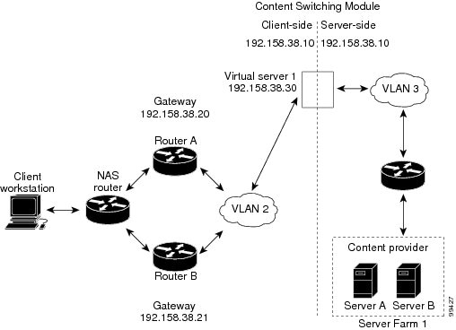
Note ![]() The addresses in Figure 4-1 refer to the steps in the following task table.
The addresses in Figure 4-1 refer to the steps in the following task table.
Note ![]() You configure single subnet (bridge) mode by assigning the same IP address to the CSM client and server VLANs.
You configure single subnet (bridge) mode by assigning the same IP address to the CSM client and server VLANs.
To configure content switching for the single subnet (bridge) mode, perform this task:
|
|
|
|
|---|---|---|
Step 1 |
Router(config-module-csm)# vlan
database
|
Enters the VLAN mode1 . |
Step 2 |
Router(vlan)# vlan 2
|
Configures a client-side VLAN2 . |
Step 3 |
Router(vlan)# vlan 3
|
Configures a server-side VLAN. |
Step 4 |
Router(vlan)# exit |
Exits to have the configuration take effect. |
Step 5 |
Router(config-module-csm)# vlan 2
client
|
Creates the client-side VLAN 2 and enters the SLB VLAN mode1. |
Step 6 |
Router(config-slb-vlan-client)# ip
addr 192.158.38.10 255.255.255.0
|
Assigns the CSM IP address on VLAN 2. |
Step 7 |
Router(config-slb-vlan-client)# gateway 192.158.38.20 |
Defines the client-side VLAN gateway to Router A. |
Step 8 |
Router(config-slb-vlan-client)# gateway 192.158.38.21 |
Defines the client-side VLAN gateway to Router B. |
Step 9 |
Router(config-slb-vserver)# vlan 3 server |
Creates the server-side VLAN 3 and enters the SLB VLAN mode. |
Step 10 |
Router(config-slb-vlan-client)# ip
addr 192.158.38.10 255.255.255.0
|
Assigns the CSM IP address on VLAN 3. |
Step 11 |
Router(config-slb-vlan-client)# exit
|
Exits the submode. |
Step 12 |
Router(config-module-csm)# vserver
VIP1
|
Creates a virtual server and enters the SLB vserver mode. |
Step 13 |
Router(config-slb-vserver)# virtual
192.158.38.30 tcp www
|
Creates a virtual IP address. |
Step 14 |
Router(config-slb-vserver)# serverfarm farm1 |
Associates the virtual server with the server farm3 . |
Step 15 |
Router(config-module-csm)# inservice |
Enables the server. |
1 Enter the exit command to leave a mode or submode. Enter the end command to return to the menu's top level. 2 The no form of this command restores the defaults. 3 This step assumes that the server farm has already been configured. (See the "Configuring Server Farms" section on page 3-12.) |
Note ![]() Set the server's default routes to Router A's gateway (192.158.38.20) or Router B's gateway (192.158.38.21).
Set the server's default routes to Router A's gateway (192.158.38.20) or Router B's gateway (192.158.38.21).
Configuring the Secure (Router) Mode
In secure (router) mode, the client-side and server-side VLANs are on different subnets. Figure 4-2 shows how the secure (router) mode configuration is set up.
Figure 4-2
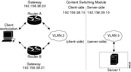
Secure (Router) Mode Configuration
Note ![]() The addresses in Figure 4-2 refer to the steps in the following task table.
The addresses in Figure 4-2 refer to the steps in the following task table.
To configure content switching in secure (router) mode, perform this task:
|
|
|
|
|---|---|---|
Step 1 |
Router(config-module-csm)# vlan database
|
Enters the VLAN mode1 . |
Step 2 |
Router(vlan)# vlan 2
|
Configures a client-side VLAN2 . |
Step 3 |
Router(vlan)# vlan 3
|
Configures a server-side VLAN. |
Step 4 |
Router(vlan)# exit |
Exits to have the configuration take effect. |
Step 5 |
Router(config-module-csm)# vlan 2 client
|
Creates the client-side VLAN 2 and enters the SLB VLAN mode. |
Step 6 |
Router(config-slb-vlan-client)# ip addr
192.158.38.10 255.255.255.0
|
Assigns the CSM IP address on VLAN 2. |
Step 7 |
Router(config-slb-vlan-client)# gateway
192.158.38.20
|
Defines the client-side VLAN gateway to Router A. |
Step 8 |
Router(config-slb-vlan-client)# gateway
192.158.38.21
|
Defines the client-side VLAN gateway to Router B. |
Step 9 |
Router(config-module-csm)# vlan 3 server |
Creates the server-side VLAN 3 and enters the SLB VLAN mode. |
Step 10 |
Router(config-slb-vlan-server)# ip addr
192.158.39.10 255.255.255.0
|
Assigns the CSM IP address on VLAN 3. |
Step 11 |
Router(config-slb-vlan-server)# exit
|
Exits the submode. |
Step 12 |
Router(config-module-csm)# vserver VIP1
|
Creates a virtual server and enters the SLB vserver mode. |
Step 13 |
Router(config-slb-vserver)# virtual
192.158.38.30 tcp www
|
Creates a virtual IP address. |
Step 14 |
Router(config-slb-vserver)# serverfarm farm1 |
Associates the virtual server with the server farm3 . |
Step 15 |
Router(config-module-csm)# inservice |
Enables the server. |
1 Enter the exit command to leave a mode or submode. Enter the end command to return to the menu's top level. 2 The no form of this command restores the defaults. 3 This step assumes that the server farm has already been configured. (See the "Configuring Server Farms" section on page 3-12.) |
Note ![]() Set the server's default routes to the CSM's IP address (192.158.39.10).
Set the server's default routes to the CSM's IP address (192.158.39.10).
Configuring Fault Tolerance
This section describes a fault-tolerant configuration. In this configuration, two separate Catalyst 6500 series chassis each contain a CSM.
Note ![]() You can also create a fault-tolerant configuration with two CSMs in a single Catalyst 6500 series chassis. You also can create a fault-tolerant configuration in either the secure (router) mode or nonsecure (bridge) mode.
You can also create a fault-tolerant configuration with two CSMs in a single Catalyst 6500 series chassis. You also can create a fault-tolerant configuration in either the secure (router) mode or nonsecure (bridge) mode.
In the secure (router) mode, the client-side and server-side VLANs provide the fault-tolerant (redundant) connection paths between the CSM and the routers on the client side and the servers on the server side. In a redundant configuration, two CSMs perform active and standby roles. Each CSM contains the same IP, virtual server, server pool, and real server information. From the client-side and server-side networks, each CSM is configured identically. The network sees the fault-tolerant configuration as a single CSM.
Note ![]() When you configure multiple fault-tolerant CSM pairs, do not configure multiple CSM pairs to use the same FT VLAN. Use a different FT VLAN for each fault-tolerant CSM pair.
When you configure multiple fault-tolerant CSM pairs, do not configure multiple CSM pairs to use the same FT VLAN. Use a different FT VLAN for each fault-tolerant CSM pair.
Configuring fault tolerance requires the following:
•![]() Two CSMs that are installed in the Catalyst 6500 series chassis.
Two CSMs that are installed in the Catalyst 6500 series chassis.
•![]() Identically configured CSMs. One CSM is configured as the active; the other is configured as the standby.
Identically configured CSMs. One CSM is configured as the active; the other is configured as the standby.
•![]() Each CSM connected to the same client-side and server-side VLANs.
Each CSM connected to the same client-side and server-side VLANs.
•![]() Communication between the CSMs provided by a shared private VLAN.
Communication between the CSMs provided by a shared private VLAN.
•![]() A network that sees the redundant CSMs as a single entity.
A network that sees the redundant CSMs as a single entity.
•![]() Connection redundancy by configuring a link that has a 1-GB per-second capacity. Enable the calendar in the switch Cisco IOS software so that the CSM state change gets stamped with the correct time.
Connection redundancy by configuring a link that has a 1-GB per-second capacity. Enable the calendar in the switch Cisco IOS software so that the CSM state change gets stamped with the correct time.
The following command enables the calendar:
Cat6k-2# conf t
Cat6k-2(config)# clock timezone WORD offset from UTC
Cat6k-2(config)# clock calendar-valid
Because each CSM has a different IP address on the client-side and server-side VLAN, the CSM can issue health monitor probes (see the "Configuring Probes for Health Monitoring" section on page 6-1) to the network and receive responses. Both the active and standby CSMs send probes while operational. If the passive CSM assumes control, it knows the status of the servers because of the probe responses it has received.
Connection replication supports both non-TCP connections and TCP connections. Enter the replicate csrp {sticky | connection} command in the virtual server mode to configure replication for the CSMs.
Note ![]() The default setting for the replicate command is disabled.
The default setting for the replicate command is disabled.
To use connection replication for connection redundancy, use these commands:
Cat6k-2# conf t
Cat6k-2(config)# no ip igmp snooping
If no router is present on the server-side VLAN, then each server's default route points to the aliased IP address.
Figure 4-3 shows how the secure (router) mode fault-tolerant configuration is set up.
Figure 4-3 Fault-Tolerant Configuration
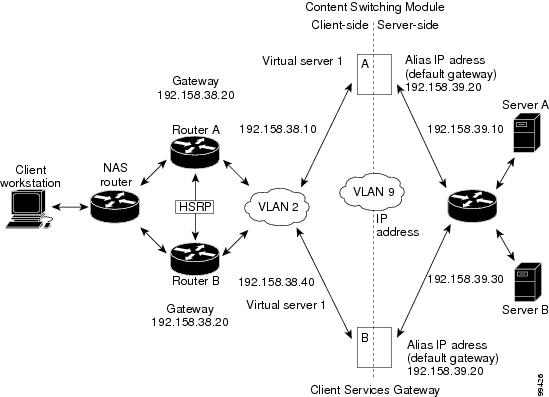
Note ![]() The addresses in Figure 4-3 refer to the steps in the following two task tables.
The addresses in Figure 4-3 refer to the steps in the following two task tables.
To configure the active (A) CSM for fault tolerance, perform this task:
|
|
|
|
|---|---|---|
Step 1 |
Router(config-module-csm)# vlan 2 client
|
Creates the client-side VLAN 2 and enters the SLB VLAN mode1 . |
Step 2 |
Router(config-slb-vlan-client)# ip addr
192.158.38.10 255.255.255.0
|
Assigns the content switching IP address on VLAN 2. |
Step 3 |
Router(config-slb-vlan-client)# gateway
192.158.38.20
|
(Optional) Defines the client-side VLAN gateway for an HSRP enabled gateway. |
Step 4 |
Router(config-module-csm)# vserver vip1
|
Creates a virtual server and enters the SLB vserver mode. |
Step 5 |
Router(config-slb-vserver)# virtual
192.158.38.30 tcp www
|
Creates a virtual IP address. |
Step 6 |
Router(config-module-csm)# inservice |
Enables the server. |
Step 7 |
Router(config-module-csm)# vlan 3 server |
Creates the server-side VLAN 3 and enters the SLB VLAN mode. |
Step 8 |
Router(config-slb-vlan-server)# ip addr
192.158.39.10 255.255.255.0
|
Assigns the CSM IP address on VLAN 3. |
Step 9 |
Router(config-slb-vlan-server)# alias ip
addr 192.158.39.20 255.255.255.0
|
Assigns the default route for VLAN 3. |
Step 10 |
Router(config-slb-vlan-server) vlan 9 |
Defines VLAN 9 as a fault-tolerant VLAN. |
Step 11 |
Router(config-module-csm)# ft group ft-group-number vlan 9 |
Creates the content switching active and standby (A/B) group VLAN 9. |
Step 12 |
Router(config-module-csm)# vlan database
|
Enters the VLAN mode1. |
Step 13 |
Router(vlan)# vlan 2
|
Configures a client-side VLAN 22 . |
Step 14 |
Router(vlan)# vlan 3
|
Configures a server-side VLAN 3. |
Step 15 |
Router(vlan)# vlan 9
|
Configures a fault-tolerant VLAN 9. |
Step 16 |
Router(vlan)# exit |
Enters the exit command to have the configuration take affect. |
1 Enter the exit command to leave a mode or submode. Enter the end command to return to the menu's top level. 2 The no form of this command restores the defaults. |
To configure the standby (B) CSM for fault tolerance, perform this task (see Figure 4-3):
|
|
|
|
|---|---|---|
Step 1 |
Router(config-module-csm)# vlan 2 client |
Creates the client-side VLAN 2 and enters the SLB VLAN mode1 . |
Step 2 |
Router(config-slb-vlan-client)# ip addr
192.158.38.40 255.255.255.0
|
Assigns the Content Switching IP address on VLAN 2. |
Step 3 |
Router(config-module-csm) vlan 9 |
Defines VLAN 9 as a fault-tolerant VLAN. |
Step 4 |
Router(config-slb-vlan-client)# gateway
192.158.38.20
|
Defines the client-side VLAN gateway. |
Step 5 |
Router(config-module-csm)# vserver vip1
|
Creates a virtual server and enters the SLB vserver mode. |
Step 6 |
Router(config-slb-vserver)# virtual
192.158.38.30 tcp www
|
Creates a virtual IP address. |
Step 7 |
Router(config-module-csm)# inservice |
Enables the server. |
Step 8 |
Router(config-module-csm)# vlan 3 server |
Creates the server-side VLAN 3 and enters the SLB vlan mode. |
Step 9 |
Router(config-slb-vserver)# ip addr
192.158.39.30 255.255.255.0
|
Assigns the CSM IP address on VLAN 3. |
Step 10 |
Router(config-slb-vserver)# alias
192.158.39.20 255.255.255.0
|
Assigns the default route for VLAN 2. |
Step 11 |
Router(config-module-csm)# ft group ft-group-number vlan 9 |
Creates the CSM active and standby (A/B) group VLAN 9. |
Step 12 |
Router(config-module-csm)# show module csm module ft |
Displays the state of the fault tolerant system. |
1 Enter the exit command to leave a mode or submode. Enter the end command to return to the menu's top level. |
Configuring HSRP
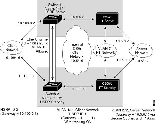
This section provides an overview of a Hot Standby Router Protocol (HSRP) configuration (see Figure 4-4) and describes how to configure the CSMs with HSRP and CSM failover on the Catalyst 6500 series switches.
HSRP Configuration Overview
Figure 4-4 shows that two Catalyst 6500 series switches, Switch 1 and Switch 2, are configured to route from a client-side network (10.100/16) to an internal CSM client network (10.6/16, VLAN 136) through an HSRP gateway (10.100.0.1). The configuration shows the following:
•![]() The client-side network is assigned an HSRP group ID of HSRP ID 2.
The client-side network is assigned an HSRP group ID of HSRP ID 2.
•![]() The internal CSM client network is assigned an HSRP group ID of HSRP ID 1.
The internal CSM client network is assigned an HSRP group ID of HSRP ID 1.
Note ![]() HSRP group 1 must have tracking turned on so that it can track the client network ports on HSRP group 2. When HSRP group 1 detects any changes in the active state of those ports, it duplicates those changes so that both the HSRP active (Switch 1) and HSRP standby (Switch 2) switches share the same knowledge of the network.
HSRP group 1 must have tracking turned on so that it can track the client network ports on HSRP group 2. When HSRP group 1 detects any changes in the active state of those ports, it duplicates those changes so that both the HSRP active (Switch 1) and HSRP standby (Switch 2) switches share the same knowledge of the network.
In the example configuration, two CSMs (one in Switch 1 and one in Switch 2) are configured to forward traffic between a client-side and a server-side VLAN:
•![]() Client VLAN 136
Client VLAN 136
Note ![]() The client VLAN is actually an internal CSM VLAN network; the actual client network is on the other side of the switch.
The client VLAN is actually an internal CSM VLAN network; the actual client network is on the other side of the switch.
•![]() Server VLAN 272
Server VLAN 272
The actual servers on the server network (10.5/1) point to the CSM server network through an aliased gateway (10.5.0.1), allowing the servers to run a secure subnet.
In the example configuration, an EtherChannel is set up with trunking enabled, allowing traffic on the internal CSM client network to travel between the two Catalyst 6500 series switches. The setup is shown in Figure 4-4.
Note ![]() EtherChannel protects against a severed link to the active switch and a failure in a non-CSM component of the switch. EtherChannel also provides a path between an active CSM in one switch and another switch, allowing CSMs and switches to fail over independently, providing an extra level of fault tolerance.
EtherChannel protects against a severed link to the active switch and a failure in a non-CSM component of the switch. EtherChannel also provides a path between an active CSM in one switch and another switch, allowing CSMs and switches to fail over independently, providing an extra level of fault tolerance.
Figure 4-4 HSRP Configuration
Creating the HSRP Gateway
This procedure describes how to create an HSRP gateway for the client-side network. The gateway is HSRP ID 2 for the client-side network.
Note ![]() In this example, HSRP is set on Fast Ethernet ports 3/6.
In this example, HSRP is set on Fast Ethernet ports 3/6.
To create an HSRP gateway, follow these steps:
Step 1 ![]() Configure Switch 1—FT1 (HSRP active) as follows:
Configure Switch 1—FT1 (HSRP active) as follows:
Router(config)#interface FastEthernet3/6
Router(config)#ip address 10.100.0.2 255.255.0.0
Router(config)#standby 2 priority 110 preempt
Router(config)#standby 2 ip 10.100.0.1
Step 2 ![]() Configure Switch 2—FT2 (HSRP standby) as follows:
Configure Switch 2—FT2 (HSRP standby) as follows:
Router(config)#interface FastEthernet3/6
Router(config)#ip address 10.100.0.3 255.255.0.0
Router(config)#standby 2 priority 100 preempt
Router(config)#standby 2 ip 10.100.0.1
Creating Fault-Tolerant HSRP Configurations
This section describes how to create a fault-tolerant HSRP secure-mode configuration. To create a nonsecure-mode configuration, enter the commands described with these exceptions:
•![]() Assign the same IP address to both the server-side and the client-side VLANs.
Assign the same IP address to both the server-side and the client-side VLANs.
•![]() Do not use the alias command to assign a default gateway for the server-side VLAN.
Do not use the alias command to assign a default gateway for the server-side VLAN.
To create fault-tolerant HSRP configurations, follow these steps:
Step 1 ![]() Configure VLANs on HSRP FT1 as follows:
Configure VLANs on HSRP FT1 as follows:
Router(config)# module csm 5
Router(config-module-csm)# vlan 136 client
Router(config-slb-vlan-client)# ip address 10.6.0.245 255.255.0.0
Router(config-slb-vlan-client)# gateway 10.6.0.1
Router(config-slb-vlan-client)# exit
Router(config-module-csm)# vlan 272 server
Router(config-slb-vlan-server)# ip address 10.5.0.2 255.255.0.0
Router(config-slb-vlan-server)# alias 10.5.0.1 255.255.0.0
Router(config-slb-vlan-server)# exit
Router(config-module-csm)# vlan 71
Router(config-module-csm)# ft group 88 vlan 71
Router(config-slb-ft)# priority 30
Router(config-slb-ft)# preempt
Router(config-slb-ft)# exit
Router(config-module-csm)# interface Vlan136
ip address 10.6.0.2 255.255.0.0
standby 1 priority 100 preempt
standby 1 ip 10.6.0.1
standby 1 track Fa3/6 10
Step 2 ![]() Configure VLANs on HSRP FT2 as follows:
Configure VLANs on HSRP FT2 as follows:
Router(config)# module csm 6
Router(config-module-csm)# vlan 136 client
Router(config-slb-vlan-client)# ip address 10.6.0.246 255.255.0.0
Router(config-slb-vlan-client)# gateway 10.6.0.1
Router(config-slb-vlan-client)# exit
Router(config-module-csm)# vlan 272 server
Router(config-slb-vlan-server)# ip address 10.5.0.3 255.255.0.0
Router(config-slb-vlan-server)# alias 10.5.0.1 255.255.0.0
Router(config-slb-vlan-server)# exit
Router(config-module-csm)# vlan 71
Router(config-module-csm)# ft group 88 vlan 71
Router(config-slb-ft)# priority 20
Router(config-slb-ft)# preempt
Router(config-slb-ft)# exit
Router(config-module-csm)# interface Vlan136
ip address 10.6.0.3 255.255.0.0
standby 1 priority 100 preempt
standby 1 ip 10.6.0.1
standby 1 track Fa3/6 10
Note ![]() To allow tracking to work, preempt must be on.
To allow tracking to work, preempt must be on.
Step 3 ![]() Configure EtherChannel on both switches as follows:
Configure EtherChannel on both switches as follows:
Router(console)# interface Port-channel100
Router(console)# switchport
Router(console)# switchport trunk encapsulation dot1q
Router(console)# switchport trunk allowed vlan 136
Note ![]() By default, all VLANs are allowed on the port channel.
By default, all VLANs are allowed on the port channel.
Step 4 ![]() To prevent problems, remove the server and FT CSM VLANs as follows:
To prevent problems, remove the server and FT CSM VLANs as follows:
Router(console)# switchport trunk remove vlan 71
Router(console)# switchport trunk remove vlan 272
Step 5 ![]() Add ports to the EtherChannel as follows:
Add ports to the EtherChannel as follows:
Router(console)# interface FastEthernet3/25
Router(console)# switchport
Router(console)# channel-group 100 mode on
 Feedback