Downloads |
 Feedback Feedback
|
Table Of Contents
Installing the Cisco uBR904 Cable Modem
Connecting the CATV Coaxial Cable
Connecting Ethernet Cables to the Cisco uBR904 Cable Modem
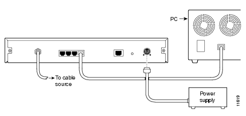
Connecting the Cisco uBR904 Cable Modem to the Computer
Console Port Connection Equipment
Starting the Cisco uBR904 Cable Modem
Installing the Cisco uBR904 Cable Modem
This chapter explains the procedures for installing and starting the Cisco uBR904 cable modem. The chapter contains the following sections:
•
Connecting the CATV Coaxial Cable
•
•
•
The most common installation location for a Cisco uBR904 cable modem is on a desktop next to a personal computer. You can also install a Cisco uBR904 cable modem on a shelf in an equipment rack, for example, if you are installing a Cisco uBR904 cable modem at a headend site for test purposes.
Connecting the CATV Coaxial Cable
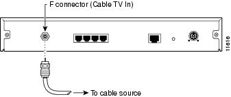
Follow these steps to connect the CATV coaxial cable to the Cisco uBR904 cable modem:
Step 1
Note
Step 2
Cisco uBR904 cable modem. This connector is labeled "Cable TV In."
(See .)Figure 3-1 Connecting the CATV Coaxial Cable to the Cisco uBR904 Cable Modem
This completes the procedure for connecting the CATV coaxial cable to the Cisco uBR904 cable modem.
Connecting Ethernet Cables to the Cisco uBR904 Cable Modem
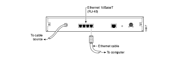
Follow these steps to connect the Ethernet cables to the Cisco uBR904 cable modem at the installation site:
Step 1
Note
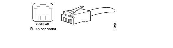
If you are connecting the Cisco uBR904 cable modem to a hub for multiple computer connections, you must use a crossover Ethernet cable. A crossover Ethernet cable is not provided with the Cisco uBR904 cable modem; however, Ethernet cables are widely available from other commercial vendors. For details on making a crossover connection, see the section, "Making a Crossover Ethernet Cable Connection" in the chapter, "," for details. If your hub has an uplink port, you might be able to use a straight-through cable to connect the hub directly to your computer.
Figure 3-2 Ethernet Cable and RJ-45 Connectors
Step 2
Figure 3-3 Connecting the Ethernet Cable to the Cisco uBR904 Cable Modem
Step 3
This completes the procedure for connecting Ethernet cables to the Cisco uBR904 cable modem.
Connecting the Cisco uBR904 Cable Modem to the Computer
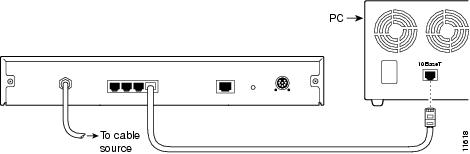
Follow these steps to connect the Cisco uBR904 cable modem to the computer at the installation site:
Step 1
Note
If you need additional information to locate the Ethernet port on the computer, consult the user documentation for the computer.
Figure 3-4 Connecting the Cisco uBR904 Cable Modem to the Computer
Step 2
This completes the procedure for connecting the Cisco uBR904 cable modem to a computer.
Connecting Console Cables
The console port for the Cisco uBR904 cable modem is located on the back of the unit. This section contains connection equipment and pinout information for the console port on the Cisco uBR904 cable modem.
Note
If you do not plan to use the console port, proceed to the section "Connecting Power," later in this chapter.Console Port Connection Equipment
The console port is configured as data communications equipment (DCE). There is one console port on the back of the Cisco uBR904 cable modem; it uses an RJ-45 connector. RJ-45-to-DB-25 adapters are available for connection to modems and other external communications equipment.
Note
Before connecting a hand-held terminal to the console port, configure the terminal to match the Cisco uBR904 cable modem console port as follows: 9600 baud, 8 data bits, no parity, 2 stop bits (9600 8N2). You need an RJ-45 console cable to connect the terminal to the console port. After you establish normal Cisco uBR904 cable modem operation, you can disconnect the terminal.
Console Port Signals
The Data Set Ready (DSR) signal is active when the system is running. The console port does not support modem control or hardware flow control. Table 3-1 lists the signals used on the console port. The console port requires an RJ-45 cable.
Table 3-1 Console Port Signals
1
-
-
-
2
DTR
—>
Data Terminal Ready
3
TxD
—>
Transmit
4
GND
-
-
5
GND
-
-
6
RxD
<—
Receive
7
DSR
<—
Data Set Ready (always on)
8
-
-
-
This completes the information necessary for connecting the console cables.
Connecting Power
Use the following procedures (see also Appendix Figure 3-5) to connect AC-input power to the Cisco uBR904 cable modem.
Step 1
Step 2
Step 3
Step 4
This completes the procedure for connecting AC-input power.
Note
Figure 3-5 Connecting the Power Cord
Starting the Cisco uBR904 Cable Modem
After installing the Cisco uBR904 cable modem and connecting the cables, start the
Cisco uBR904 cable modem as follows:
Step 1
Step 2
Cisco uBR904 cable modem boot is complete (a few minutes), the OK LED stays on and the ACT (cable) LED goes on.Step 3
Cisco uBR904 cable modem, a connection should be established to the Cisco uBR7246 universal broadband router installed at the cable headend. The Cisco uBR904 cable modem will be automatically configured by the universal broadband router.
Note
If the Cisco uBR904 cable modem completes each of the steps in the startup procedure, proceed to the section "Verifying the Installation" to verify that the connection to the network is working properly.This completes the installation of the Cisco uBR904 cable modem.