Downloads |
 Feedback Feedback
|
Table Of Contents
Preventing Electrostatic Discharge Damage
Personal Computer Hardware and Software
Installing the Cisco uBR904 Cable Modem at the Headend
Preventive Site Configuration: Maintaining Normal Operation
Making a Crossover Ethernet Cable Connection
Cisco uBR904 Cable Modem Installation Checklist
Preparing for Installation
This chapter describes the equipment and site requirements for installing the Cisco uBR904 cable modem. The chapter contains the following sections:
•
Cisco uBR904 Cable Modem Installation Checklist
Before installing the Cisco uBR904 cable modem, you should consider the power and cabling requirements that must be in place at the installation site, the equipment you will need to install the Cisco uBR904 cable modem, and the environmental conditions the installation site must meet to maintain normal operation. This chapter guides you through the process of preparing for the Cisco uBR904 cable modem installation.
Note
We highly recommend that a cable headend technician be available, or on-call, to assist you with troubleshooting Cisco uBR904 cable modem installations; especially during the early field installations. Contact your cable service provider for more information.Safety Recommendations
The following guidelines will help to ensure your safety and protect the equipment. This list does not cover all potentially hazardous situations, so be alert.
•
•
•
•
•
•
•
•
Safety with Electricity
Follow these basic guidelines when working with any electrical equipment:
•
•
•
•
•
•
In addition, use the guidelines that follow when working with any equipment that is disconnected from a power source, but still connected to cable wiring.
•
•
•
•
Preventing Electrostatic Discharge Damage
Electrostatic discharge (ESD) damage, which occurs when electronic cards or components are improperly handled, can result in complete or intermittent system failures. The
Cisco uBR904 cable modem consists of a printed circuit board that is housed in a metal enclosure. Electromagnetic interference (EMI) shielding and connectors are integral components of the enclosure. Although the enclosure helps protect the boards, use an antistatic strap (if one is available) whenever handling the Cisco uBR904 cable modem.Following are guidelines for preventing ESD damage:
•
Cisco uBR904 cable modem.•

Caution
FCC Requirements
For Class A Equipment
This equipment has been tested and found to comply with the limits for a Class A digital device, pursuant to Part 15 of the FCC Rules. These limits are designed to provide reasonable protection against harmful interference when the equipment is operated in a commercial environment. This equipment generates, uses, and can radiate radio frequency energy and, if not installed and used in accordance with the instruction manual, may cause harmful interference to radio communications. Operation of this equipment in a residential area is likely to cause harmful interference in which case the user will be required to correct the interference at his own expense.
For Class B Equipment
This equipment has been tested and found to comply with the limits for a Class B digital device, pursuant to Part 15 of the FCC Rules. These limits are designed to provide reasonable protection against harmful interference in a residential installation. This equipment generates, uses and can radiate radio frequency energy and, if not installed and used in accordance with the instructions, may cause harmful interference to radio communications. However, there is no guarantee that interference will not occur in a particular installation. If this equipment does cause harmful interference to radio or television reception, which can be determined by turning the equipment off and on, the user is encouraged to try to correct the interference by one or more of the following measures:
•
•
•
•
Note
CISPR 22 Requirements
Specifications covered:
•
•
Site Requirements
To assure normal operation and avoid unnecessary maintenance, plan your site configuration and prepare your site before installation. After installation, make sure the site maintains an ambient temperature of 23° to 113°F (-5° to 45°C), and keep the area around the chassis as free from dust as is practical.
The following sections address the site environment requirements for the Cisco uBR904 cable modem.
AC Power
The AC-input power supply in the Cisco uBR904 cable modem uses a power factor corrector that allows the Cisco uBR904 cable modem to operate on input voltage and frequency within the ranges of 100 to 240 VAC and 50/60 Hz.
Refer to in the chapter "" for system power specifications, including input voltage and operating frequency ranges.
Wiring and Cabling
Following are guidelines for setting up the wiring and cabling at the installation site. When planning the location of the Cisco uBR904 cable modem, consider the issues of electromagnetic interference (EMI), coaxial cable quality, and distance limitations for signaling, as described in the following sections.
Interference Considerations
When wires are run for any significant distance in an electromagnetic field, interference can occur between the field and the signals on the wires. This fact has two implications for the construction of plant wiring:
•
•
Note
If wires exceed recommended distances, or if wires pass between buildings, give special consideration to the effect of a lightning strike in your vicinity. The electromagnetic pulse caused by lightning or other high-energy phenomena can easily couple enough energy into unshielded conductors to destroy electronic devices. If you have had problems of this sort in the past, you might want to consult experts in electrical surge suppression and shielding.
Coaxial Cable Quality
CATV coaxial cable quality can vary dramatically at each installation site. Poor insulation, improperly installed additional outlets, the condition and length of the cable's center conductor, and the quality of the cable can negatively affect the connectivity and performance of the Cisco uBR904 cable modem for digital data transmission. Coaxial cable tolerances for the transmission of two-way digital data are much lower than the tolerances for the transmission of downstream-only video. Coaxial cable used to carry two-way digital data must be of very high quality.
Note
A small reduction in signal quality for digital data might completely disrupt service to a Cisco uBR904 cable modem user.Check the cables for general quality level, tears or cuts in the insulation, insulation that is at least 80% braid with foil, a broken or bent center conductor at the conductor ends, the length of the center conductor, and splitters or amplifiers that have been added to extend video connectivity at the installation site.
Note
We recommend that you replace any cable that is in question to begin the installation with clean, two-way digital data transmission media. If the cable is of high-quality and was recently installed, replacing the connectors with high-quality connectors can also improve performance.

Caution
Distance Limitations
The size of your networks and the distances between connections on the CATV network can affect the successful installation of a Cisco uBR904 cable modem.
When preparing a site for network connections to the Cisco uBR904 cable modem, you must consider several factors related to the cabling:
•
•
•
Potential distance limitation problems in the CATV network can be reduced by ensuring the following factors:
•
•
•
•
Cisco uBR904 cable modemPersonal Computer Hardware and Software
The Cisco uBR904 cable modem must be connected to a personal computer at the installation site. We recommend a personal computer with the following configuration:
•
•
•
•
•
Installing the Cisco uBR904 Cable Modem at the Headend
You can mount the Cisco uBR904 cable modem on an equipment shelf at the headend provided that the rack dimensions allow you to secure the router to the shelf, and the overall configuration permits safe installation and access.
Note
Figure 2-1 shows the Cisco uBR904 cable modem footprint and outer dimensions.
Figure 2-1 Cisco uBR904 Cable Modem Footprint and Outer Dimensions
Site Environment
lists the operating and nonoperating environmental site requirements. The following ranges are those within which the Cisco uBR904 cable modem will continue to operate; however, a measurement that is approaching the minimum or maximum of a range indicates a potential problem. You can maintain normal operation by anticipating and correcting environmental anomalies before they approach a maximum operating range.
•
•
•

Caution
Table 2-1 Specifications for Operating and Nonoperating Environments
Preventive Site Configuration: Maintaining Normal Operation
Planning a proper location for the Cisco uBR904 cable modem is essential for successful system operation. Equipment placed too close together or inadequately ventilated can cause system overtemperature conditions. In addition, poor equipment placement can make system maintenance difficult. Following are precautions that can help avoid problems during installation and ongoing operation.
General Precautions
Follow these general precautions when planning your equipment locations and connections:
•
•
Power Considerations
Follow these precautions and recommendations when planning power connections to the Cisco uBR904 cable modem:
•
•
Tools for Installation
Each Cisco uBR904 cable modem chassis is fully assembled at the factory; no assembly is required. However, you will need the following tools and equipment to install the cable modem:
•
•
•
•
•
•
In addition, you might need the following external equipment:
•
•
•
•
•
•
Making a Crossover Ethernet Cable Connection
The RJ-45 receptacle supports standard straight-through and crossover Category 5 UTP (RJ-45) cables. Cisco Systems does not supply Category 5 UTP cables; these cables are available commercially.
Figure 2-2 shows the RJ-45 receptacle and plug. Table 2-2 lists the pinouts and signals for the RJ-45 receptacle.
Figure 2-2 RJ-45 Receptacle and Plug
Warning
To avoid electric shock, do not connect safety extra-low voltage (SELV) circuits to telephone-network voltage (TNV) circuits. LAN ports contain SELV circuits, and WAN ports contain TNV circuits. Some LAN and WAN ports both use RJ-45 connectors. Use caution when connecting cables.
Table 2-2 RJ-45 Receptacle Pinouts
Note
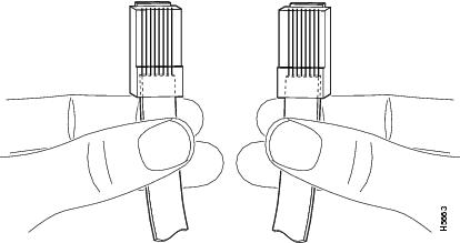
To identify the RJ-45 cable type, hold the two ends of the cable next to each other so you can see the colored wires inside the ends, as shown in .
Figure 2-3 RJ-45 Cable Identification
Examine the sequence of colored wires to determine the type of RJ-45 cable:
•
•
Configuration Information
After you install the Cisco uBR904 cable modem, verify that all the hardware is operating properly, verify that the computer is configured for IP and DHCP services, and establish a connection to the headend, the Cisco uBR904 cable modem will be configured by software downloaded from the Cisco uBR7246 universal broadband router installed at the headend. You do not need to perform any manual configuration on the Cisco uBR904 cable modem unit itself.
Note
Cisco uBR904 Cable Modem Installation Checklist
To assist you with your installation and to provide a historical record of what was done and by whom, use the Cisco uBR904 Cable Modem Installation Checklists in and . Make a copy of this checklist and indicate when each procedure or verification is completed. When the checklist is completed, place it in your site log (described at the end of this chapter) along with the other records for your new Cisco uBR904 cable modem.
Table 2-3 Cisco uBR904 Cable Modem Installation Site Checklist
Table 2-4 Cisco uBR904 Cable Modem Installation Task Checklist
Site Log
A site log provides a historical record of all actions relevant to the Cisco uBR904 cable modem operation and maintenance. Keep the site log in a common place where anyone who performs tasks has access to it. Site log entries might include the following:
•
•
•
•
•
shows a sample site log page. Make copies of the sample or design your own site log to meet the needs of your installation site and equipment.
Table 2-5 Site Log Example