- Preface
- Product Overview
- Configuring the Router for the First Time
- Configuring a Supervisor Engine 720
- Configuring a Route Switch Processor 720
- Configuring NSF with SSO Supervisor Engine Redundancy
- ISSU and eFSU on Cisco 7600 Series Routers
- Configuring RPR and RPR+ Supervisor Engine Redundancy
- Configuring Interfaces
- Configuring a Supervisor Engine 32
- Configuring LAN Ports for Layer 2 Switching
- Configuring Flex Links
- Configuring EtherChannels
- Configuring VTP
- Configuring VLANs
- Configuring Private VLANs
- Configuring Cisco IP Phone Support
- Configuring IEEE 802.1Q Tunneling
- Configuring Layer 2 Protocol Tunneling
- Configuring L2TPv3
- Configuring STP and MST
- Configuring Optional STP Features
- Configuring Layer 3 Interfaces
- Configuring GTP-SLB IPV6 Support
- IP Subscriber Awareness over Ethernet
- Configuring UDE and UDLR
- Configuring Multiprotocol Label Switching on the PFC
- Configuring IPv4 Multicast VPN Support
- Configuring Multicast VPN Extranet Support
- Configuring IP Unicast Layer 3 Switching
- Configuring IPv6 Multicast PFC3 and DFC3 Layer 3 Switching
- Configuring IPv4 Multicast Layer 3 Switching
- Configuring MLDv2 Snooping for IPv6 Multicast Traffic
- Configuring IGMP Snooping for IPv4 Multicast Traffic
- Configuring PIM Snooping
- Configuring Network Security
- Understanding Cisco IOS ACL Support
- Configuring VRF aware 6RD Tunnels
- Configuring VLAN ACLs
- Private Hosts (Using PACLs)
- Configuring IPv6 PACL
- IPv6 First-Hop Security Features
- Configuring Online Diagnostics
- Configuring Denial of Service Protection
- Configuring DHCP Snooping
- Configuring Dynamic ARP Inspection
- Configuring Traffic Storm Control
- Unknown Unicast Flood Blocking
- Configuring PFC QoS
- Configuring PFC QoS Statistics Data Export
- Configuring MPLS QoS on the PFC
- Configuring LSM MLDP based MVPN Support
- Configuring IEEE 802.1X Port-Based Authentication
- Configuring IEEE 802.1ad
- Configuring Port Security
- Configuring UDLD
- Configuring NetFlow and NDE
- Configuring Local SPAN, RSPAN, and ERSPAN
- Configuring SNMP IfIndex Persistence
- Power Management and Environmental Monitoring
- Configuring Web Cache Services Using WCCP
- Using the Top N Utility
- Using the Layer 2 Traceroute Utility
- Configuring Bidirectional Forwarding and Detection over Switched Virtual Interface
- Configuring Call Home
- Configuring IPv6 Policy Based Routing
- Using the Mini Protocol Analyzer
- Configuring Resilient Ethernet Protocol
- Configuring Synchronous Ethernet
- Configuring Link State Tracking
- Configuring BGP PIC Edge and Core for IP and MPLS
- Configuring VRF aware IPv6 tunnels over IPv4 transport
- ISIS IPv4 Loop Free Alternate Fast Reroute (LFA FRR)
- Multicast Service Reflection
- Y.1731 Performance Monitoring
- Online Diagnostic Tests
- Acronyms
- Cisco IOS Release 15S Software Images
- Index
Cisco 7600 Series Router Software Configuration Guide, Cisco IOS Release 15S
Bias-Free Language
The documentation set for this product strives to use bias-free language. For the purposes of this documentation set, bias-free is defined as language that does not imply discrimination based on age, disability, gender, racial identity, ethnic identity, sexual orientation, socioeconomic status, and intersectionality. Exceptions may be present in the documentation due to language that is hardcoded in the user interfaces of the product software, language used based on RFP documentation, or language that is used by a referenced third-party product. Learn more about how Cisco is using Inclusive Language.
- Updated:
- July 31, 2014
Chapter: Configuring IPv4 Multicast VPN Support
- Understanding How MVPN Works
- MVPN Configuration Guidelines and Restrictions
- Configuring MVPN
- Configuring Egress and Ingress Multicast Replication Mode
- Configuring a Multicast VPN Routing and Forwarding Instance
- Configuring Multicast VRF Routing
- Enabling IPv4 Multicast Routing Globally
- Enabling IPv4 Multicast VRF Routing
- Configuring a PIM VRF Register Message Source Address
- Specifying the PIM VRF Rendezvous Point (RP) Address
- Configuring a Multicast Source Discovery Protocol (MSDP) Peer
- Enabling IPv4 Multicast Header Storage
- Configuring the Maximum Number of Multicast Routes
- Configuring IPv4 Multicast Route Filtering
- Sample Configuration
- Displaying IPv4 Multicast VRF Routing Information
- Configuring Interfaces for Multicast Routing to Support MVPN
Configuring Multicast VPN Support
This chapter describes how to configure Multicast Virtual Private Network (MVPN) support on Cisco 7600 series routers. MVPN is supported when a PFC3B, PFC3BXL, PFC3C, or PFC3CXL is installed in the router.

Note For complete syntax and usage information for the commands used in this chapter, refer to the Cisco 7600 Series Routers Command References at this URL:
http://www.cisco.com/en/US/products/hw/routers/ps368/prod_command_reference_list.html
Understanding How MVPN Works
- MVPN Overview
- Multicast Routing and Forwarding and Multicast Domains
- Multicast Distribution Trees
- Multicast Tunnel Interfaces
- PE Router Routing Table Support for MVPN
- Multicast Distributed Switching Support
- Hardware-Assisted IPv4 Multicast
MVPN Overview
MVPN is a standards-based feature that transmits IPv4 multicast traffic across an MPLS VPN cloud. MVPN on Cisco 7600 series routers uses the existing PFC hardware support for IPv4 multicast traffic to forward multicast traffic over VPNs at wire speeds. MVPN adds support for IPv4 multicast traffic over Layer 3 IPv4 VPNs to the existing IPv4 unicast support.
MVPN routes and forwards multicast packets for each individual VPN routing and forwarding (VRF) instance, as well as transmitting the multicast packets through VPN tunnels across the service provider backbone.
MVPN is an alternative to IP-in-IP generic route encapsulation (GRE) tunnels. GRE tunnels are not a readily scalable solution and they are limited in the granularity they provide to customers.
Multicast Routing and Forwarding and Multicast Domains
MVPN adds multicast routing information to the VPN routing and forwarding table. When a provider-edge (PE) router receives multicast data or control packets from a customer-edge (CE) router, forwarding is performed according to the information in the multicast VRF (MVRF).
Note![]() MVRF is also commonly referred to as multicast over VRF-lite.
MVRF is also commonly referred to as multicast over VRF-lite.
Each MVRF maintains the routing and forwarding information that is needed for its particular VRF instance. An MVRF is created and configured in the same way as existing VRFs, except multicast routing is also enabled on each MVRF.
A multicast domain constitutes the set of hosts that can send multicast traffic to each other within the MPLS network. For example, the multicast domain for a customer that wanted to send certain types of multicast traffic to all global employees would consist of all CE routers associated with that enterprise.
Multicast Distribution Trees
The MVPN feature establishes at least one multicast distribution tree (MDT) for each multicast domain. The MDT provides the information needed to interconnect the same MVRFs that exist on the different PE routers.
- Default MDT—The default MDT is a permanent channel for PIM control messages and low-bandwidth streams between all PE routers in a particular multicast domain. All multicast traffic in the default MDT is replicated to every other PE router in the domain. Each PE router is logically seen as a PIM neighbor (one hop away) from every other PE router in the domain.
- Data MDT—Data MDTs are optional. If enabled, they are dynamically created to provide optimal paths for high-bandwidth transmissions, such as full-motion video, that do not need to be sent to every PE router. This allows for on-demand forwarding of high-bandwidth traffic between PE routers, so as to avoid flooding every PE router with every high-bandwidth stream that might be created.
To create data MDTs, each PE router that is forwarding multicast streams to the backbone periodically examines the traffic being sent in each default MDT as follows:
1.![]() Each PE router periodically samples the multicast traffic (approximately every 10 seconds for software switching, and 90 seconds for hardware switching) to determine whether a multicast stream has exceeded the configured threshold. (Depending on when the stream is sampled, this means that in a worst-case scenario, it could take up to 180 seconds before a high-bandwidth stream is detected.)
Each PE router periodically samples the multicast traffic (approximately every 10 seconds for software switching, and 90 seconds for hardware switching) to determine whether a multicast stream has exceeded the configured threshold. (Depending on when the stream is sampled, this means that in a worst-case scenario, it could take up to 180 seconds before a high-bandwidth stream is detected.)
Note![]() Data MDTs are created only for (S, G) multicast route entries within the VRF multicast routing table. They are not created for (*, G) entries.
Data MDTs are created only for (S, G) multicast route entries within the VRF multicast routing table. They are not created for (*, G) entries.
2.![]() If a particular multicast stream exceeds the defined threshold, the sending PE router dynamically creates a data MDT for that particular multicast traffic.
If a particular multicast stream exceeds the defined threshold, the sending PE router dynamically creates a data MDT for that particular multicast traffic.
3.![]() The sending PE router then transmits a DATA-MDT JOIN request (which is a User Datagram Protocol (UDP) message to port 3232) to the other PE routers, informing them of the new data MDT.
The sending PE router then transmits a DATA-MDT JOIN request (which is a User Datagram Protocol (UDP) message to port 3232) to the other PE routers, informing them of the new data MDT.
4.![]() Receiving PE routers examine their VRF routing tables to determine if they have any customers interested in receiving this data stream. If so, they use the PIM protocol to transmit a PIM JOIN message for this particular data MDT group (in the global table PIM instance) to accept the stream. Routers that do not currently have any customers for this stream still cache the information, in case any customers request it later on.
Receiving PE routers examine their VRF routing tables to determine if they have any customers interested in receiving this data stream. If so, they use the PIM protocol to transmit a PIM JOIN message for this particular data MDT group (in the global table PIM instance) to accept the stream. Routers that do not currently have any customers for this stream still cache the information, in case any customers request it later on.
5.![]() Three seconds after sending the DATA-MDT JOIN message, the sending PE router removes the high-bandwidth multicast stream from the default MDT and begins transmitting it over the new data MDT.
Three seconds after sending the DATA-MDT JOIN message, the sending PE router removes the high-bandwidth multicast stream from the default MDT and begins transmitting it over the new data MDT.
6.![]() The sending PE router continues to send a DATA-MDT JOIN message every 60 seconds, as long as the multicast stream continues to exceed the defined threshold. If the stream falls below the threshold for more than 60 seconds, the sending PE router stops sending the DATA-MDT JOIN messages, and moves the stream back to the default MDT.
The sending PE router continues to send a DATA-MDT JOIN message every 60 seconds, as long as the multicast stream continues to exceed the defined threshold. If the stream falls below the threshold for more than 60 seconds, the sending PE router stops sending the DATA-MDT JOIN messages, and moves the stream back to the default MDT.
7.![]() Receiving routers age out the cache information for the default MDT when they do not receive a DATA-MDT JOIN message for more than three minutes.
Receiving routers age out the cache information for the default MDT when they do not receive a DATA-MDT JOIN message for more than three minutes.
Data MDTs allow for high-bandwidth sources inside the VPN while still ensuring optimal traffic forwarding in the MPLS VPN core.
Note![]() For technical information about the DATA-MDT JOIN message and other aspects of the data MDT creation and usage, see the Internet-Draft, Multicast in MPLS/BGP IP VPNs, by Eric C. Rosen et al.
For technical information about the DATA-MDT JOIN message and other aspects of the data MDT creation and usage, see the Internet-Draft, Multicast in MPLS/BGP IP VPNs, by Eric C. Rosen et al.
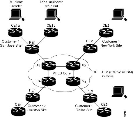
In the following example, a service provider has a multicast customer with offices in San Jose, New York, and Dallas. The San Jose site is transmitting a one-way multicast presentation. The service provider network supports all three sites associated with this customer, in addition to the Houston site of a different enterprise customer.
The default MDT for the enterprise customer consists of provider routers P1, P2, and P3 and their associated PE routers. Although PE4 is interconnected to these other routers in the MPLS core, PE4 is associated with a different customer and is therefore not part of the default MDT.
Figure 27-1 shows the situation in this network when no one outside of San Jose has joined the multicast broadcast, which means that no data is flowing along the default MDT. Each PE router maintains a PIM relationship with the other PE routers over the default MDT, as well as a PIM relationship with its directly attached PE routers.
Figure 27-1 Default Multicast Distribution Tree Overview
If an employee in New York joins the multicast session, the PE router associated for the New York site sends a join request that flows across the default MDT for the multicast domain. The PE router associated with the multicast session source (PE1) receives the request. Figure 27-2 shows how the PE router forwards the request to the CE router associated with the multicast source (CE1a).
Figure 27-2 Initializing the Data MDT
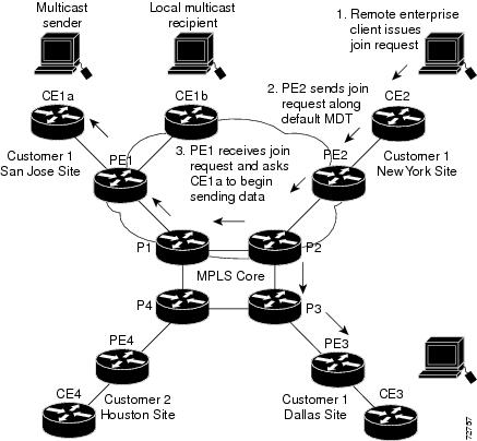
The CE router (CE1a) starts sending the multicast data to the associated PE router (PE1), which recognizes that the multicast data exceeds the bandwidth threshold at which a data MDT should be created. PE1 then creates a data MDT and sends a message to all routers using the default MDT that contains information about the data MDT.
Approximately three seconds later, PE1 begins sending the multicast data for that particular stream using the data MDT. Because only PE2 has receivers who are interested in this source, only PE2 joins the data MDT and receives traffic on it.
Multicast Tunnel Interfaces
The PE router creates a multicast tunnel interface (MTI) for each multicast VRF (MVRF) in the multicast domain. The MVRF uses the tunnel interface to access the multicast domain to provide a conduit that connects an MVRF and the global MVRF.
On the router, the MTI is a tunnel interface (created with the interface tunnel command) with a class D multicast address. All PE routers that are configured with a default MDT for this MVRF create a logical network in which each PE router appears as a PIM neighbor (one hop away) to every other PE router in the multicast domain, regardless of the actual physical distance between them.
The MTI is automatically created when an MVRF is configured. The BGP peering address is assigned as the MTI interface source address, and the PIM protocol is automatically enabled on each MTI.
When the router receives a multicast packet from the customer side of the network, it uses the incoming interface’s VRF to determine which MVRFs should receive it. The router then encapsulates the packet using GRE encapsulation. When the router encapsulates the packet, it sets the source address to that of the BGP peering interface and sets the destination address to the multicast address of the default MDT, or to the source address of the data MDT if configured. The router then replicates the packet as needed for forwarding on the appropriate number of MTI interfaces.
When the router receives a packet on the MTI interface, it uses the destination address to identify the appropriate default MDT or data MDT, which in turn identifies the appropriate MVRF. It then decapsulates the packet and forwards it out the appropriate interfaces, replicating it as many times as are necessary.
Note ●![]() Unlike other tunnel interfaces that are commonly used on Cisco routers, the MVPN MTI is classified as a LAN interface, not a point-to-point interface. The MTI interface is not configurable, but you can use the show interface tunnel command to display its status.
Unlike other tunnel interfaces that are commonly used on Cisco routers, the MVPN MTI is classified as a LAN interface, not a point-to-point interface. The MTI interface is not configurable, but you can use the show interface tunnel command to display its status.
- The MTI interface is used exclusively for multicast traffic over the VPN tunnel.
- The tunnel does not carry unicast routed traffic.
PE Router Routing Table Support for MVPN
Each PE router that supports the MVPN feature uses the following routing tables to ensure that the VPN and MVPN traffic is routed correctly:
- Default routing table—Standard routing table used in all Cisco routers. This table contains the routes that are needed for backbone traffic and for non-MPLS VPN unicast and multicast traffic (including Generic Routing Encapsulation (GRE) multicast traffic).
- VPN routing/forwarding (VRF) table—Routing table created for each VRF instance. Responsible for routing the unicast traffic between VPNs in the MPLS network.
- Multicast VRF (MVRF) table—Multicast routing table and multicast routing protocol instance created for each VRF instance. Responsible for routing the multicast traffic in the multicast domain of the network. This table also includes the multicast tunnel interfaces that are used to access the multicast domain.
Multicast Distributed Switching Support
MVPN supports multicast distributed switching (MDS) for multicast support on a per-interface and a per-VRF basis. When configuring MDS, you must make sure that no interface (including loopback interfaces) has the no ip mroute-cache command configured.
Hardware-Assisted IPv4 Multicast
The PFC supports hardware acceleration for IPv4 multicast over VPN traffic, which forwards multicast traffic to the appropriate VPNs at wire speed without increased MSFC3 CPU utilization.
In a customer VRF, PFC hardware acceleration supports multicast traffic in PIM dense, PIM sparse, PIM bidirectional, and PIM Source Specific Multicast (SSM) modes.
In the service provider core, PFC hardware acceleration supports multicast traffic in PIM sparse, PIM bidirectional, and PIM SSM modes. In the service provider core, PFC hardware acceleration does not support multicast traffic in PIM dense mode.
MVPN Configuration Guidelines and Restrictions
When configuring MVPN, follow these guidelines and restrictions:
- The Cisco 7600 series router must have a PFC3B, PFC3BXL, PFC3C, or PFC3CXL installed to run MVPN.
- All PE routers in the multicast domain need to be running a Cisco IOS software image that supports the MVPN feature. There is no requirement for MVPN support on the P and CE routers.
- Support for IPv4 multicast traffic must also be enabled on all backbone routers.
- The Border Gateway Protocol (BGP) routing protocol must be configured and operational on all routers supporting multicast traffic. In addition, BGP extended communities must be enabled (using the neighbor send-community both or neighbor send-community extended command) to support the use of MDTs in the network.
- Only ingress replication is supported when MVPN is configured. If the router is currently configured for egress replication, it is forced into ingress replication when the first MVRF is configured.
- When the router is acting as a PE, and receives a multicast packet from a customer router with a time-to-live (TTL) value of 2, it drops the packet instead of encapsulating it and forwarding it across the MVPN link. Because such packets would normally be dropped by the PE at the other end of the MVPN link, this does not affect traffic flow.
- If the core multicast routing uses SSM, then the data and default multicast distribution tree (MDT) groups must be configured within the SSM range of IPv4 addresses.
- The update source interface for the BGP peerings must be the same for all BGP peerings configured on the router in order for the default MDT to be configured properly. If you use a loopback address for BGP peering, then PIM sparse mode must be enabled on the loopback address.
- The ip mroute-cache command must be enabled on the loopback interface used as the BGP peering interface in order for distributed multicast switching to function on the platforms that support it. The no ip mroute-cache command must not be present on these interfaces.
- Data MDTs are not created for VRF PIM dense mode multicast streams because of the flood and prune nature of dense mode multicast flows and the resulting periodic bring-up and tear-down of such data MDTs.
- Data MDTs are not created for VRF PIM bidirectional mode because source information is not available.
- MVPN does not support multiple BGP peering update sources, and configuring them can break MVPN RPF checking. The source IPv4 address of the MVPN tunnels is determined by the highest IPv4 address used for the BGP peering update source. If this IPv4 address is not the IPv4 address used as the BGP peering address with the remote PE router, MVPN will not function properly.
- MDT tunnels do not carry unicast traffic.
- Although MVPN uses the infrastructure of MPLS VPN networks, you cannot apply MPLS tags or labels to multicast traffic over the VPNs.
- Each MVRF that is configured with a default MDT uses three hidden VLANs (one each for encapsulation, decapsulation, and interface), in addition to external, user-visible VLANs. This means that an absolute maximum of 1,000 MVRFs are supported on each router. (MVRFs without a configured MDT still use one internal VLAN, so unused MVRFs should be deleted to conserve VLAN allocation.)
- Because MVPN uses MPLS, MVPN supports only the RPR and RPR+ redundancy modes. MPLS can coexist with NSF with SSO redundancy mode, but there is no support for stateful MPLS switchover.
- If your MPLS VPN network already contains a network of VRFs, you do not need to delete them or recreate them to be able to support MVRF traffic. Instead, configure the mdt default and mdt data commands, as listed in the following procedure, to enable multicast traffic over the VRF.
- BGP should be already configured and operational on all routers that are sending or receiving multicast traffic. In addition, BGP extended communities must be enabled (using the neighbor send-community both or neighbor send-community extended command) to support the use of MDTs in the network.
- The same MVRF must be configured on each PE router that is to support a particular VPN connection.
- Each PE router that supports a particular MVRF must be configured with the same mdt default command.
- In Cisco IOS Release 15.0(1)S egress and ingress replication modes are supported when MVPN is configured on the Cisco 7600 series router. The router can be configured either for ingress or egress replication mode.
- 20k is the maximum supported scale for native multicast.
Configuring MVPN
These sections describe how to configure MVPN:
- Configuring Egress and Ingress Multicast Replication Mode
- Configuring a Multicast VPN Routing and Forwarding Instance
- Configuring Multicast VRF Routing
- Configuring Interfaces for Multicast Routing to Support MVPN
Note![]() These configuration tasks assume that BGP is already configured and operational on all routers that are sending or receiving the multicast traffic. In addition, BGP extended communities must be enabled (using the neighbor send-community both or neighbor send-community extended command) to support the use of MDTs in the network.
These configuration tasks assume that BGP is already configured and operational on all routers that are sending or receiving the multicast traffic. In addition, BGP extended communities must be enabled (using the neighbor send-community both or neighbor send-community extended command) to support the use of MDTs in the network.
Configuring Egress and Ingress Multicast Replication Mode
To configure either egress or ingress multicast replication mode, use the following commands:
The following is a sample output of the running-configuration, when the ingress replication mode is changed to egress replication mode:
This example shows how to verify the multicast replication mode:
If the current replication mode is egress or if any of the switching modules are capable of egress replication mode, configure ingress replication mode during a scheduled maintenance period to minimize the disruption of customer traffic.
To configure ingress multicast replication mode, perform this task:
This example shows how to configure ingress multicast replication mode and verify the configuration:
Configuring a Multicast VPN Routing and Forwarding Instance
These sections describe how to configure a multicast VPN routing and forwarding (MVRF) instance for each VPN connection on each PE router that is to handle the traffic for each particular VPN connection that is to transmit or receive multicast traffic:
Configuring a VRF Entry
To configure a VRF entry, perform this task:
|
|
|
|
|---|---|---|
Configures a VRF routing table entry and a Cisco Express Forwarding (CEF) table entry and enters VRF configuration mode. |
||
This example show how to configure a VRF named blue and verify the configuration:
Configuring the Route Distinguisher
To configure the route distinguisher, perform this task:
|
|
|
|
|---|---|---|
|
|
||
When configuring the route distinguisher, enter the route distinguisher in one of the following formats:
- 16-bit AS number:your 32-bit number (101:3)
- 32-bit IPv4 address:your 16-bit number (192.168.122.15:1)
This example show how to configure 55:1111 as the route distinguisher and verify the configuration:
Configuring the Route-Target Extended Community
To configure the route-target extended community, perform this task:
When configuring the route-target extended community, note the following information:
- import —Imports routing information from the target VPN extended community.
- export —Exports routing information to the target VPN extended community.
- both —Imports and exports.
- route_target_ext_community —Adds the 48-bit route-target extended community to the VRF. Enter the number in one of the following formats:
–![]() 16-bit AS number:your 32-bit number (101:3)
16-bit AS number:your 32-bit number (101:3)
–![]() 32-bit IPv4 address:your 16-bit number (192.168.122.15:1)
32-bit IPv4 address:your 16-bit number (192.168.122.15:1)
This example shows how to configure 55:1111 as the import and export route-target extended community and verify the configuration:
Router(config-vrf)# route-target both 55:1111
Router(config-vrf)# do show ip vrf detail
VRF blue; default RD 55:1111; default VPNID <not set>
Connected addresses are not in global routing table
Export VPN route-target communities
Configuring the Default MDT
To configure the default MDT, perform this task:
|
|
|
|---|---|
When configuring the default MDT, note the following:
- The group_address is the multicast IPv4 address of the default MDT group. This address serves as an identifier for the MVRF community, because all provider-edge (PE) routers configured with this same group address become members of the group, which allows them to receive the PIM control messages and multicast traffic that are sent by other members of the group.
- This same default MDT must be configured on each PE router to enable the PE routers to receive multicast traffic for this particular MVRF.
This example shows how to configure 239.1.1.1 as the default MDT:
Configuring Data MDTs (Optional)
To configure optional data MDTs, perform this task:
When configuring optional data MDTs, note the following information:
- group_address1 —Multicast group address. The address can range from 224.0.0.1 to 239.255.255.255, but cannot overlap the address that has been assigned to the default MDT.
- wildcard_bits —Wildcard bitmask to be applied to the multicast group address to create a range of possible addresses. This allows you to limit the maximum number of data MDTs that each MVRF can support.
- threshold threshold_value —(Optional) Defines the threshold value in kilobits, at which multicast traffic should be switched from the default MDT to the data MDT. The threshold_value parameter can range from 1 through 4294967 kilobits.
- list access_list —(Optional) Specifies an access list name or number to be applied to this traffic.
Enabling Data MDT Logging
To enable data MDT logging, perform this task:
Sample Configuration
The following excerpt from a configuration file shows typical VRF configurations for a range of VRFs. To simplify the display, only the starting and ending VRFs are shown.
Displaying VRF Information
To display all of the VRFs that are configured on the router, use the show ip vrf command:
To display information about the MDTs that are currently configured for all MVRFs, use the show ip pim mdt command. The following example shows typical output for this command:
Note![]() To display information about a specific tunnel interface, use the show interface tunnel command. The IPv4 address for the tunnel interface is the multicast group address for the default MDT of the MVRF.
To display information about a specific tunnel interface, use the show interface tunnel command. The IPv4 address for the tunnel interface is the multicast group address for the default MDT of the MVRF.
To display entries for a specific VRF, use the show platform software multicast ip vrf command. The following example shows typical output for this command:
To display routing information for a particular VRF, use the show ip route vrf command:
To display information about the multicast routing table and tunnel interface for a particular MVRF, use the show ip mroute vrf command. The following example shows typical output for a MVRF named BIDIR01:
Note![]() In this example, the show ip mroute vrf command shows that Tunnel1 is the MDT tunnel interface (MTI) being used by this VRF.
In this example, the show ip mroute vrf command shows that Tunnel1 is the MDT tunnel interface (MTI) being used by this VRF.
Configuring Multicast VRF Routing
These sections describe how to configure multicast routing to support MVPN:
- Enabling IPv4 Multicast Routing Globally
- Enabling IPv4 Multicast VRF Routing
- Configuring a PIM VRF Register Message Source Address
- Specifying the PIM VRF Rendezvous Point (RP) Address
- Configuring a Multicast Source Discovery Protocol (MSDP) Peer
- Enabling IPv4 Multicast Header Storage
- Configuring the Maximum Number of Multicast Routes
- Sample Configuration
- Displaying IPv4 Multicast VRF Routing Information
Note![]() BGP should be already configured and operational on all routers that are sending or receiving multicast traffic. In addition, BGP extended communities must be enabled (using the neighbor send-community both or neighbor send-community extended command) to support the use of MDTs in the network.
BGP should be already configured and operational on all routers that are sending or receiving multicast traffic. In addition, BGP extended communities must be enabled (using the neighbor send-community both or neighbor send-community extended command) to support the use of MDTs in the network.
Enabling IPv4 Multicast Routing Globally
To enable IPv4 multicast routing globally, perform this task:
|
|
|
|
|---|---|---|
This example show how to enable IPv4 multicast routing globally:
Enabling IPv4 Multicast VRF Routing
To enable IPv4 multicast VRF routing, perform this task:
|
|
|
|---|---|
Router(config)# ip multicast-routing vrf vrf_name [ distributed ] |
|
When enabling IPv4 multicast VRF routing, note the following information:
- vrf_name —Specifies a particular VRF for multicast routing. The vrf_name should refer to a VRF that has been previously created, as specified in the “Configuring a Multicast VPN Routing and Forwarding Instance” section.
- distributed —(Optional) Enables Multicast Distributed Switching (MDS).
Configuring a PIM VRF Register Message Source Address
To configure a PIM VRF register message source address, perform this task:
This example show how to configure a PIM VRF register message source address:
Specifying the PIM VRF Rendezvous Point (RP) Address
To specify the PIM VRF RP address, perform this task:
When specifying the PIM VRF RP address, note the following information:
- vrf vrf_name —(Optional) Specifies a particular VRF instance to be used.
- rp_address —Unicast IP address for the PIM RP router.
- access_list —(Optional) Number or name of an access list that defines the multicast groups for the RP.
- override —(Optional) In the event of conflicting RP addresses, this particular RP overrides any RP that is learned through Auto-RP.
- bidir —(Optional) Specifies that the multicast groups specified by the access_list argument are to operate in bidirectional mode. If this option is not specified, the groups operate in PIM sparse mode.
- Use bidirectional mode whenever possible, because it offers better scalability.
Configuring a Multicast Source Discovery Protocol (MSDP) Peer
To configure an MSDP peer, perform this task:
When configuring an MSDP peer, note the following information:
- vrf vrf_name —Specifies a particular VRF instance to be used.
- { peer_name | peer_address }—Domain Name System (DNS) name or IP address of the MSDP peer router.
- connect-source interface_type interface_number —Interface name and number for the interface whose primary address is used as the source IP address for the TCP connection.
- remote-as ASN —(Optional) Autonomous system number of the MSDP peer. This is for display-only purposes.
This example show how to configure an MSDP peer:
Router(config)# ip msdp peer router.cisco.com connect-source fastethernet 1/1 remote-as 109
Enabling IPv4 Multicast Header Storage
To enable IPv4 multicast header storage, perform this task:
When enabling IPv4 multicast header storage, note the following information:
- vrf vrf_name —Allocates a buffer for the specified VRF.
- rtp —(Optional) Also caches Real-Time Transport Protocol (RTP) headers.
- The buffers can be displayed with the show ip mpacket command.
This example show how to enable IPv4 multicast header storage:
Configuring the Maximum Number of Multicast Routes
To configure the maximum number of multicast routes, perform this task:
When configuring the maximum number of routes, note the following information:
- vrf vrf_name — Enables route limiting for the specified VRF.
- limit —The number of multicast routes that can be added. The range is from 1 to 2147483647, with a default of 2147483647.
- threshold —(Optional) Number of multicast routes that can be added before a warning message occurs. The valid range is from 1 to the value of the limit parameter.
This example show how to configure the maximum number of multicast routes:
Router(config)# ip multicast vrf blue route-limit 200000 20000
Configuring IPv4 Multicast Route Filtering
To configure IPV4 multicast route filtering, perform this task:
|
|
|
|---|---|
(Optional) Configures IPV4 multicast route filtering with an access list. The access_list parameter can be the name or number of a access list. |
|
This example show how to configure IPV4 multicast route filtering:
Sample Configuration
The following excerpt from a configuration file shows the minimum configuration that is needed to support multicast routing for a range of VRFs. To simplify the display, only the starting and ending VRFs are shown.
Displaying IPv4 Multicast VRF Routing Information
To display the known PIM neighbors for a particular MVRF, use the show ip pim vrf neighbor command:
Configuring Interfaces for Multicast Routing to Support MVPN
These sections describe how to configure interfaces for multicast routing to support MVPN:
Multicast Routing Configuration Overview
Protocol Independent Multicast (PIM) must be configured on all interfaces that are being used for IPv4 multicast traffic. In a VPN multicast environment, you should enable PIM on at least all of the following interfaces:
- Physical interface on a provider edge (PE) router that is connected to the backbone.
- Loopback interface that is used for BGP peering.
- Loopback interface that is used as the source for the sparse PIM rendezvous point (RP) router address.
In addition, you must also associate MVRFs with those interfaces over which they are going to forward multicast traffic.
BGP should be already configured and operational on all routers that are sending or receiving multicast traffic. In addition, BGP extended communities must be enabled (using the neighbor send-community both or neighbor send-community extended command) to support the use of MDTs in the network.
Configuring PIM on an Interface
To configure PIM on an interface, perform this task:
When configuring PIM on an interface, note the following information:
–![]() A physical interface on a provider edge (PE) router that is connected to the backbone.
A physical interface on a provider edge (PE) router that is connected to the backbone.
–![]() A loopback interface that is used for BGP peering.
A loopback interface that is used for BGP peering.
–![]() A loopback interface that is used as the source for the sparse PIM network rendezvous point (RP) address.
A loopback interface that is used as the source for the sparse PIM network rendezvous point (RP) address.
–![]() dense-mode —Enables dense mode of operation.
dense-mode —Enables dense mode of operation.
–![]() sparse-mode —Enables sparse mode of operation.
sparse-mode —Enables sparse mode of operation.
–![]() sparse-dense-mode —Enables sparse mode if the multicast group has an RP router defined, or enables dense mode if an RP router is not defined.
sparse-dense-mode —Enables sparse mode if the multicast group has an RP router defined, or enables dense mode if an RP router is not defined.
- Use sparse-mode for the physical interfaces of all PE routers that are connected to the backbone, and on all loopback interfaces that are used for BGP peering or as the source for RP addressing.
This example shows how to configure PIM sparse mode on a physical interface:
interface gigabitethernet 10/1
Router(config-if)# ip pim sparse-mode
This example shows how to configure PIM sparse mode on a loopback interface:
Configuring an Interface for IPv4 VRF Forwarding
To configure an interface for IPv4 VRF forwarding, perform this task:
This example shows how to configure the interface for VRF blue forwarding:
Sample Configuration
The following excerpt from a configuration file shows the interface configuration, along with the associated MVRF configuration, to enable multicast traffic over a single MVRF:
Sample Configurations for MVPN
This section contains the following sample configurations for the MVPN feature:
MVPN Configuration with Default MDTs Only
The following excerpt from a configuration file shows the lines that are related to the MVPN configuration for three MVRFs. (The required BGP configuration is not shown.)
MVPN Configuration with Default and Data MDTs
The following sample configuration includes three MVRFs that have been configured for both default and data MDTs. Only the configuration that is relevant to the MVPN configuration is shown.
IPv6 Multicast Virtual Private Network (MVPNv6)
To provide layer 3 multicast services to customers with multiple distributed sites, service providers need a secure and scalable mechanism to transmit multicast traffic across the service provider network. IPv4 Multicast VPN(MVPN) provides such services for IPv4 multicast traffic over a shared service provider backbone.
Since many service providers are migrating to IPv6, they also need the same services for IPv6 multicast traffic. IPv6 Multicast Virtual Private Network (MVPNv6) provides multiple VPN support that enables service providers to provide multicast enabled private IPv6 networks to their customers using the same IPv4 back bone. In MVPNv6 implementation, the IPv6 multicast traffic is carried over the same IPv4 based core network and hence both the IPv4 and IPv6 VPN traffic are carried over the same tunnels simultaneously. Effective with Cisco IOS release 15.2(4)S, MVPNv6 is supported on Cisco 7600 series routers.
Restrictions for the MVPNv6 Feature
Following restrictions apply to MVPNv6 on the Cisco 7600 series routers:
- Support up to 8000 IPv6 routes in VRF.
- Support up to 60 multicast VRFs.
- For MVPNv6 support, MVPNv4 should co-exist.
- All core facing cards should be ES+ line cards.
- Point to Point GRE tunnel as output interface in VRF for MVPNv6 is not supported.
- Default Multicast Distribution Tree (MDT) and data MDT are supported.
- An IPv6 protocol inside a VRF should operate in ingress replication mode irrespective of the configured replication mode. IPv4 backbone can operate in both ingress and egress replication modes.
- Effective with Cisco IOS Release 15.3(1)S, if replication mode is Egress, the entries in v6-vrf lite is installed as Egress. Before this release, it was Ingress.
- MVRF with MDT default configured on IPv4 and IPv6 address families (dual stack) does not support SVI as core facing interface.
Configurng MPVNv6
Configuring MVPNv6 includes the following procedures:
1.![]() Configuring Multicast VRF Instances on PE Routers
Configuring Multicast VRF Instances on PE Routers
2.![]() Configuring Multicast Routing
Configuring Multicast Routing
3.![]() Configuring Multicast VRF Interfaces on PE Routers
Configuring Multicast VRF Interfaces on PE Routers
4.![]() Configuring Routing Protocols Between the PE and CE Routers
Configuring Routing Protocols Between the PE and CE Routers
Note![]() These configuration tasks assume that BGP is already configured and operational on all routers sending or receiving the multicast traffic. Additionally, BGP extended communities must be enabled (using the neighbor send-community both or neighbor send-community extended command) to support the use of MDTs in the network.
These configuration tasks assume that BGP is already configured and operational on all routers sending or receiving the multicast traffic. Additionally, BGP extended communities must be enabled (using the neighbor send-community both or neighbor send-community extended command) to support the use of MDTs in the network.
Configuring Multicast VRF Instances on PE Routers
Complete these steps to configure Multicast VRFs on PE routers.
Summary Steps
6.![]() route-target {import | export | both} route-target-ext-community
route-target {import | export | both} route-target-ext-community
10.![]() mdt data group_address wildcard_bits [threshold threshold_value ] [list access_list ]
mdt data group_address wildcard_bits [threshold threshold_value ] [list access_list ]
14.![]() mdt data group_address wildcard_bits [threshold threshold_value ] [list access_list ]
mdt data group_address wildcard_bits [threshold threshold_value ] [list access_list ]
Detailed Steps
Configuring Multicast Routing
Summary Steps
3.![]() ip multicast-routing [ vrf vrf-name ]
ip multicast-routing [ vrf vrf-name ]
Detailed Steps
Configuring Multicast VRF Interfaces on PE Routers
Complete these steps to configure IPv6 Multicast VRF interfaces.
Summary Steps
9.![]() ipv6 address ipv6-address link-local
ipv6 address ipv6-address link-local
10.![]() ipv6 address ipv6-address/prefix
ipv6 address ipv6-address/prefix
Detailed Steps
Configuring Routing Protocols Between the PE and CE Routers
Configure the PE router with the same routing protocol that the CE router uses. In this configuration, EIGRP is used as the routing protocol between PE and CE routers. Complete these steps to configure EIGRP as the routing protocol between PE and CE Routers.
Summary Steps
2.![]() address-family ipv6 vrf vrf-name
address-family ipv6 vrf vrf-name
Detailed Steps
Configuration Examples
This example shows how to configure MVPNv6 on the Cisco 7600 series routers. In this example, EIGRP is used as the routing protocol between PE and CE routers.
Note![]() These configuration tasks are based on the assumption that BGP is already configured and operational on all routers sending or receiving the multicast traffic.
These configuration tasks are based on the assumption that BGP is already configured and operational on all routers sending or receiving the multicast traffic.
Router(config)# vrf definition blue
Router(config-if)# ip address 10.1.0.1 255.255.0.0
Verifying MVPNv6 Configuration
Use these commands to verify the MVPNv6 configuration.
 Feedback