- Preface
- Product Overview
- Configuring the Router for the First Time
- Configuring a Supervisor Engine 720
- Configuring a Route Switch Processor 720
- Configuring NSF with SSO Supervisor Engine Redundancy
- ISSU and eFSU on Cisco 7600 Series Routers
- Configuring RPR and RPR+ Supervisor Engine Redundancy
- Configuring Interfaces
- Configuring a Supervisor Engine 32
- Configuring LAN Ports for Layer 2 Switching
- Configuring Flex Links
- Configuring EtherChannels
- Configuring VTP
- Configuring VLANs
- Configuring Private VLANs
- Configuring Cisco IP Phone Support
- Configuring IEEE 802.1Q Tunneling
- Configuring Layer 2 Protocol Tunneling
- Configuring L2TPv3
- Configuring STP and MST
- Configuring Optional STP Features
- Configuring Layer 3 Interfaces
- Configuring GTP-SLB IPV6 Support
- IP Subscriber Awareness over Ethernet
- Configuring UDE and UDLR
- Configuring Multiprotocol Label Switching on the PFC
- Configuring IPv4 Multicast VPN Support
- Configuring Multicast VPN Extranet Support
- Configuring IP Unicast Layer 3 Switching
- Configuring IPv6 Multicast PFC3 and DFC3 Layer 3 Switching
- Configuring IPv4 Multicast Layer 3 Switching
- Configuring MLDv2 Snooping for IPv6 Multicast Traffic
- Configuring IGMP Snooping for IPv4 Multicast Traffic
- Configuring PIM Snooping
- Configuring Network Security
- Understanding Cisco IOS ACL Support
- Configuring VRF aware 6RD Tunnels
- Configuring VLAN ACLs
- Private Hosts (Using PACLs)
- Configuring IPv6 PACL
- IPv6 First-Hop Security Features
- Configuring Online Diagnostics
- Configuring Denial of Service Protection
- Configuring DHCP Snooping
- Configuring Dynamic ARP Inspection
- Configuring Traffic Storm Control
- Unknown Unicast Flood Blocking
- Configuring PFC QoS
- Configuring PFC QoS Statistics Data Export
- Configuring MPLS QoS on the PFC
- Configuring LSM MLDP based MVPN Support
- Configuring IEEE 802.1X Port-Based Authentication
- Configuring IEEE 802.1ad
- Configuring Port Security
- Configuring UDLD
- Configuring NetFlow and NDE
- Configuring Local SPAN, RSPAN, and ERSPAN
- Configuring SNMP IfIndex Persistence
- Power Management and Environmental Monitoring
- Configuring Web Cache Services Using WCCP
- Using the Top N Utility
- Using the Layer 2 Traceroute Utility
- Configuring Bidirectional Forwarding and Detection over Switched Virtual Interface
- Configuring Call Home
- Configuring IPv6 Policy Based Routing
- Using the Mini Protocol Analyzer
- Configuring Resilient Ethernet Protocol
- Configuring Synchronous Ethernet
- Configuring Link State Tracking
- Configuring BGP PIC Edge and Core for IP and MPLS
- Configuring VRF aware IPv6 tunnels over IPv4 transport
- ISIS IPv4 Loop Free Alternate Fast Reroute (LFA FRR)
- Multicast Service Reflection
- Y.1731 Performance Monitoring
- Online Diagnostic Tests
- Acronyms
- Cisco IOS Release 15S Software Images
- Index
Cisco 7600 Series Router Software Configuration Guide, Cisco IOS Release 15S
Bias-Free Language
The documentation set for this product strives to use bias-free language. For the purposes of this documentation set, bias-free is defined as language that does not imply discrimination based on age, disability, gender, racial identity, ethnic identity, sexual orientation, socioeconomic status, and intersectionality. Exceptions may be present in the documentation due to language that is hardcoded in the user interfaces of the product software, language used based on RFP documentation, or language that is used by a referenced third-party product. Learn more about how Cisco is using Inclusive Language.
- Updated:
- July 31, 2014
Chapter: IP Subscriber Awareness over Ethernet
- Overview
- IP Subscriber Session Features
- IP Address Assignment
- PPPoE and IPoE Session Support on Port Channel (1:1 Redundancy)
- PPPoE and IPoE Session Support on QinQ Subinterfaces with IEEE 802.1AH Customer Ethertype
- QoS Recommendations
- Bandwidth-Remaining Ratio Recommendations
- Priority-Rate Propagation Recommendations
- Unsupported IP Subscriber Session Features
- IP Subscriber Awareness over Ethernet Configuration Guidelines
- Configuring IP Subscriber Awareness over Ethernet
- Command Reference
- interface access
IP Subscriber Awareness over Ethernet
This chapter provides information about how various Cisco 7600 features are being scaled to support the IP Subscriber Awareness over Ethernet feature (sometimes referred to as IP subscriber aggregation), which was introduced for the Cisco 7600 series router in Cisco IOS Release 12.2SRB. From Cisco IOS Release 12.2(33)SRE onwards, the ISG functionality in distributed IP and PPPoE sessions on Cisco 7600 series routers is supported on Ethernet Services Plus (ES+) access-facing line cards. From Cisco IOS Release 12.2(33)SRE8 onwards, Intelligent Services Gateway (ISG) will be disabled for ES+ Low Queue cards.
This chapter contains the following sections:
- Overview
- IP Subscriber Session Features
- IP Subscriber Awareness over Ethernet Configuration Guidelines
- Configuring IP Subscriber Awareness over Ethernet
- Command Reference

Note![]() Effective with Cisco IOS Release 15.2(4)S, the Broadband (IP and PPPoE sessions) support is deprecated in Cisco 7600 routers.
Effective with Cisco IOS Release 15.2(4)S, the Broadband (IP and PPPoE sessions) support is deprecated in Cisco 7600 routers.
Overview
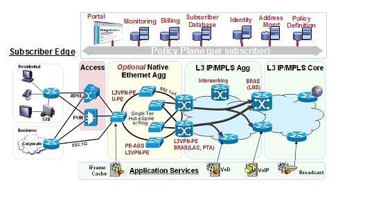
IP Subscriber Awareness over Ethernet is designed for use in an architecture in which the Cisco 7600 router is used as a DSLAM Gigabit Ethernet (GE) aggregator. In this scenario, the DSLAM is connected to the router through a physical port that can carry data for multiple VLANs.
The IP Subscriber Awareness over Ethernet feature supports two models of carrying services between the subscriber and the DSLAM:
- Per-service VLAN model—One or more ATM VCs is used to carry each type of service (video, voice, and data) between the subscriber and the VLAN.
- Per-subscriber VLAN model—A single ATM VC is used to carry all traffic (video, voice, and data) between the subscriber and the DSLAM.
Figure 24-1 shows an example of a wireline Ethernet architecture where IP Subscriber Awareness over Ethernet might be used.
Figure 24-1 Wireline Ethernet Architecture
The following sections provide more details about the IP Subscriber Awareness over Ethernet feature:
Benefits
The IP Subscriber Awareness over Ethernet feature provides the following benefits:
- IP session termination and IP session aggregation on the Cisco 7600 router.
- Support for up to 32000 IP subscribers on a router (with a maximum of 8000 subscribers on a single Cisco 7600 SIP-400).
- Interface scalability to support up to 32000 interfaces on the router.
–![]() Support for up to 1000 subinterfaces on each physical port.
Support for up to 1000 subinterfaces on each physical port.
–![]() Support for up to 8000 subinterfaces on each Cisco 7600 SIP-400.
Support for up to 8000 subinterfaces on each Cisco 7600 SIP-400.
- DHCP and Radius accounting for IP subscribers. Support for 256 DHCP pools, and DHCP can handle up to 150 calls per second for IP subscriber sessions.
- QoS support for individual IP subscribers (up to 32000 subscribers), including: classification (IP prec and DSCP), policing, shaping, marking, priority queues, and weighted random early detection (WRED).
- Per-subscriber statistics and accounting information.
- Support for up to 96000 ARP entries.
- RPR, RPR+, stateful switchover (SSO), and non-stop forwarding (NSF) are provided for the IP subscribers.
- Control plane protection (CoPP) protects against denial of service (DOS) and other attacks.
IP Subscriber Interfaces
Cisco IOS Release 12.2SRB introduces a new type of interface to represent IP subscribers:
- Access—A subinterface that represents an individual IP subscriber. The access subinterface can be configured for.1Q or Q-in-Q encapsulation.
You apply traffic shaping and policing policies (including HQoS) to the access interface to define the amount of bandwidth to allocate for different types of subscriber traffic (for example, voice and data).
Note![]() You configure the access interface as a subinterface of the physical interface that the IP subscriber is connected to.
You configure the access interface as a subinterface of the physical interface that the IP subscriber is connected to.
The following example shows an access subinterface on the interface :
IP Subscriber Session
An IP subscriber session exists while an IP subscriber is using its shared VLAN to access the network. To begin an IP subscriber session, the router must assign an IP address to the subscriber’s access subinterface. You can either assign a static IP address to the subinterface, or you can allow DHCP to assign an address. Following are some notes about both methods of assigning an IP address:
- Static IP address—If you assign a static IP address to the access subinterface, the IP subscriber session is considered to always be Up. We recommend that you do not configure many IP subscribers with static IP addresses.
- DHCP-assigned IP address—You can allow DHCP to assign an IP address for the subscriber session. An IP subscriber session begins when the router receives a DHCP discover packet for the subscriber and an IP address is assigned for the subscriber. The session is terminated when the subscriber receives a DHCP release message and its IP address is released. If the subscriber session is VRF aware (that is, if the subscriber belongs to a VRF), the VRF-aware DHCP pool must be used.
Note ●![]() The router can be operating as a DHCP server or DHCP relay device.
The router can be operating as a DHCP server or DHCP relay device.
- To configure an IP subscriber as part of a VRF (that is, to make the subscriber session VRF aware), configure the VRF under the access subinterface.
This feature supports the following sessions in a ES+ line card:
- IP sessions (routed and L2-connected)
- DHCP integration with IP sessions
- Static IP subnet sessions
- Source IP address and MAC address sessions (IP sessions)
- PPPoE supported in the PPP Termination and Aggregation (PTA) mode
- PPPoEoVLAN supported in the PTA mode
- PPPoEoQinQ supported in the PTA mode
- PPPoEoDot1Q supported in the PTA mode
IP Subscriber Session Features
The following features are provided for IP subscriber sessions:
- Per-subscriber control plane policing and protection (CoPP)—Provides protection against denial of service (DOS) and other attacks for individual subscribers. When an attack occurs, the router notifies the network administrator and begins policing the malicious traffic. This feature allows policing of ARP, DHCP, and ICMP traffic. For information about how CoPP operates on the Cisco 7600 SIP-400, see:
http://www.cisco.com/en/US/products/hw/routers/ps368/module_installation_and_configuration_guides_chapter09186a0080440138.html#wp1351662
- Per-subscriber security ACL—Allows you to apply security access control lists (ACLs) to individual subscribers. For information about how this feature works on the Cisco 7600 SIP-400, see:
http://www.cisco.com/en/US/products/hw/routers/ps368/module_installation_and_configuration_guides_chapter09186a0080440138.html#wp1351562
- Per-subscriber Radius accounting—Enables system administrators to track IP session activity for individual subscribers, and to extract subscriber accounting records periodically. Per-subscriber Radius accounting works with DHCP IP address assignment, and improves the authentication, authorization, and accounting (AAA) of broadband service delivery. For information about this feature, see its feature description at:
http://www.cisco.com/univercd/cc/td/doc/product/software/ios122sr/newft/122srb33/ipradacc.htm
- Lawful intercept—Enables a Law Enforcement Agency (LEA) to perform electronic surveillance on a subscriber as authorized by a court order. To assist in the surveillance, the service provider intercepts the subscriber’s traffic as it passes through one of their routers, and sends a copy of the intercepted traffic to the LEA without the subscriber’s knowledge. For information about this feature, see the documents at the following URLs:
http://www.cisco.com/univercd/cc/td/doc/product/core/cis7600/76licfg/index.htm
http://www.cisco.com/en/US/products/hw/routers/ps368/module_installation_and_configuration_guides_chapter09186a0080440138.html#wp1351508
- Quality of Service—Standard QoS features are supported for individual subscribers (access subinterfaces), including classification, marking, policing, shaping, priority queuing, and weighted random early detection (WRED). For information about recommended QoS settings for IP Subscriber Awareness over Ethernet, see the following section (“QoS Recommendations”). For information about QoS features on the Cisco 7600 SIP-400, see the information about QoS features in the “Cisco 7600 SIP-400 Features” section of the document at this URL:
http://www.cisco.com/en/US/products/hw/routers/ps368/module_installation_and_configuration_guides_chapter09186a008044013b.html#wp1094663
In addition to standard QoS features, the following new Cisco 7600 SIP-400 QoS features are being introduced to support the deployment of broadband services:
- Dual-priority queues—Provide two priority queues for voice and video traffic for 4000 to 8000 subscribers. You can assign a different priority level to each traffic class to configure the router to treat both types of traffic as priority traffic but to handle them differently (for example, by giving voice traffic precedence over video traffic).
- Bandwidth-remaining ratio (BRR)—Allows service providers to prioritize subscriber traffic during periods of congestion. You can use the Distribution of Remaining Bandwidth Using Ratio feature to specify the relative weight of a subinterface or class queue with respect to other subinterfaces or queues. For information about this feature, see the “Bandwidth-Remaining Ratio Recommendations” section.
- Priority-rate propagation—Takes the priority level and traffic rate assigned to priority traffic in a low-level queue and applies that level and rate to priority traffic at all higher-level queues in the queue hierarchy, even if those queues are not specifically configured for minimum rates or priority. For more information, see the “Priority-Rate Propagation Recommendations” section.
IP Address Assignment
- DHCP Based IP address assignment: If DHCP is being used to assign IP addresses, and the IP address that is assigned by DHCP is correct for the service domain, ISG does not have to be involved in the assignment of an IP address for the subscriber. If the IP address that is assigned by DHCP is not correct for the service domain, or if the domain changes because of a VRF transfer, ISG can be configured to influence the DHCP IP address assignment.
- Static IP address assignment: If a subscriber’s static IP address is configured correctly for the service domain, ISG is not involved in the assignment of an IP address for the subscriber.
- IP subnet: For IP subnet sessions, the IP subnet is specified in the user profile.
IP interface: ISG is not involved in the assignment of subscriber IP addresses.
IP Subnet (IP Range) Sessions
A client subnet identifies a IP Subnet session and applies uniform edge processing to packets associated with a particular IP subnet. IP Subnet sessions are hosted for clients directly connected or over multiple hops. The following functionalities are not supported on IP Subnet Sessions, but are supported on IP Sessions:
IP Interface Sessions
In an IP Interface session, all the traffic received on a particular physical or logical interface is collated. However, dynamic VRF transfer is not supported in an IP interface session and, VRF transfer can only be used with static VRF configuration. Irrespective of the subsriber logged in, a session is created by default.
PPPoE and IPoE Session Support on Port Channel (1:1 Redundancy)
The 1:1 redundancy on a port channel coupled with Link Aggregation Control Protocol (LACP) dynamically handles the member links in a port channel bundle. A port channel has two members, of which one member is active and the other is in standby or redundant mode. The member ports can be across line cards, but must originate from Ethernet Services Plus (ES+) line card. At any given point of time, one link is on the physical mode.
The following sessions support 1:1 redundancy in a ES+ line card:
PPPoE and IPoE Session Support on QinQ Subinterfaces with IEEE 802.1AH Customer Ethertype
This feature enables you to implement PPPoE and IPoE session (ISG functions) on QinQ subinterfaces that are configured with custom ethertype. The custom ethertype implemented on the main interface is inherited by all the subinterfaces. To implement this feature, use dot1q tunnel ethertype command on main interface for the respective QinQ subinterfaces.
If the outer VLAN tag on a PPPoE or IPoE session packet matches the custom ethertype VLAN settings on the QinQ subinterface, the packets are accepted otherwise the packets are dropped. You can set the outer VLAN tag to the following values:
The PPPoE or IPoE session will not come up if tthere is mismatch i the ether type between ISG and the client. For example, if the outer VLAN tag on a packet is set to 0x9100 and the interface is configured using custom ethertype to accept only packets with 0x88a8 VLAN tag, the packet will be dropped in the QinQ subinterface. Figure x-x shows an ethernet frame format for QinQ (need the figure)
You can create a QinQ subinterface using the access keyword while defining an interface. The following code shows how to define an interface with access keyword, create a VLAN QinQ subinterface, and enable PPPoE session:
Restictions and Usage Guidelines
Follow these restrictions and usage guidelines when you configure an IP or a PPPoE sessions on an ES+ linecard:
- IP Sessions are not supported on ambiguous VLANs.
- Radius proxy is not supported for the IP Sessions.
- IP and MAC address spoof Prevention is not supported on subinterfaces on a ES+ linecard unlike on a SIP400 line card.
- IP sessions are supported on Link Aggregation (Ether-Channel) interfaces. LAG etherchannel interfaces are supported for links on the same and across line cards.
- PPPoE sessions are supported on ambiguous VLAN interfaces and VLAN ranges.
- There are no drop counters to identify the number of packets dropped due to custom ethertype mismatch.
- VLANs, Source MAC Address, and Ports are matched against session ids to extend security for PPPoE sessions.
Follow these restrictions and usage guidelines when you configure 1:1 redundancy on a ES+ linecard:
- Subscriber redundancy is available only on a 1:1 access standby model.
- Supports access interfaces in port channels to scale the number of port channel subinterfaces to greater than 4k.
- Link Aggregation Control Protocol (LACP) allows dynamic handling of member links in a GEC bundle.
- Supports a maximum of 64 GEC bundles with 8 links.
- Member links in a single GEC bundle reside across NPs or the linecard.
- LAG is supported with members across linecards.
- Supports LAG across linecards and membership of the LAG does not change after new sessions are initiated.
- Feature supports 32000 access subinterfaces and 8K access interfaces.
- Supports per session load balancing across member links where all the traffic for a session is relayed over a single port.
- To reduce the downtime during member link addition or deletion, QOS queues are allocated for all member links belonging to the port channel. Though the ingress and egress traffic could be on different member links, the peer relays all the traffic for a session through a single member link.
- LAG supports sessions on non access subinterfaces to support coexistence of multicast streams.
Verification
This section lists the commands to display configuration information.
QoS Recommendations
When you configure QoS features on the Cisco 7600 SIP-400 for use with the IP Subscriber Awareness over Ethernet feature, note the following configuration guidelines and recommendations:
- The Cisco 7600 SIP-400 is capable of throughput of 5.1 to 5.6 gigabits per second (Gbps). We recommend that you do not oversubscribe the card beyond 8 Gbps. Beyond this limit, the card’s behavior is unpredictable. [CSCsg67629]
- Oversubscription is supported only on the 5-Port Gigabit Ethernet SPA (SPA-5X1GE-V2).
- High-priority traffic (typically voice and video) must have an IP precedence value of 5, 6, or 7.
- IP precedence values of 0, 1, 2, 3, or 4 will result in drops if oversubscription occurs, even if the traffic is classified as priority traffic in a QoS policy. [CSCsg67721]
Note![]() We strongly recommend that the IP precedence value and VLAN user priority values of packets match. If ingress oversubscription occurs, priority traffic with non-matching IP precedence and VLAN user priority values might be dropped at the SPA level. [CSCsg97434]
We strongly recommend that the IP precedence value and VLAN user priority values of packets match. If ingress oversubscription occurs, priority traffic with non-matching IP precedence and VLAN user priority values might be dropped at the SPA level. [CSCsg97434]
- High-priority traffic (typically voice) must have VLAN user priority values of 5, 6, or 7. Priority values of 0, 1, 2, 3, or 4 will result in drops if oversubscription occurs, even if the traffic is classified as priority traffic by a QoS policy. [CSCsg97434, CSCsg67721]
- To obtain statistics for an individual IP subscriber session, issue the show policy-map interface command two or three times. This is necessary because the counters retain their existing values the first time you issue the command.
- If you issue the show policy-map interface command and do not specify an interface, the router must update all of the session counters. With 32000 subscribers, this can take up to 30 minutes.
Bandwidth-Remaining Ratio Recommendations
The Bandwidth-Remaining Ratio (BRR) feature (also called Distribution of Remaining Bandwidth Using Ratio) allows service providers to prioritize subscriber traffic during periods of congestion. You can use the feature to specify the relative weight of a subinterface or class queue with respect to other subinterfaces or queues. During congestion, the router uses the bandwidth-remaining ratio to optimize the scheduling of uncommitted bandwidth on subinterfaces and class queues. Without BRR, the unassigned bandwidth on a physical interface is equally distributed among all queues. For an overview of this feature, see its feature description at:
http://www.cisco.com/univercd/cc/td/doc/product/software/ios122sb/newft/122sb31/bwratio.htm
This section provides recommendations and guidelines for configuring BRR on the Cisco 7600 SIP-400 to support IP Subscriber Awareness over Ethernet. It contains the following sections:
BRR Configuration Guidelines
Observe the following Cisco 7600 specific guidelines and considerations as you configure this feature:
- Supported only on the Cisco 7600 SIP-400 with 2-port and 5-port Gigabit Ethernet (GE) SPAs.
- Available only on GE interfaces (because the feature is only supported on GE SPAs).
- Requires RSP720, Sup720, or Sup32.
- If two subinterfaces have bandwidth remaining ratios that vary greatly (for example, 1000 to 1), you must configure a low queue limit (between 2 and 50) for the child default class of the subinterface with the lower ratio. Without a low queue limit, the packets that are buffered due to the default queue-limit value are allowed to pass after traffic is stopped, which affects bandwidth remaining ratios significantly. Configuring a low queue limit ensures that the ratios are maintained even after the traffic is stopped.
Note![]() We recommend that you use BRR with priority-rate propagation. See the “Priority-Rate Propagation Recommendations” section for more information.
We recommend that you use BRR with priority-rate propagation. See the “Priority-Rate Propagation Recommendations” section for more information.
BRR Configuration Instructions
Following is a summary of the steps required to configure configure a QoS policy that defines BRR for a subscriber (access) interface on the Cisco 7600 SIP-400. The following table provides detailed instructions.
Note![]() The command lines include only those arguments and keywords required to configure BRR.
The command lines include only those arguments and keywords required to configure BRR.
3.![]() qos scheduler priority-rate-propagation platform sip-400 (optional but recommended)
qos scheduler priority-rate-propagation platform sip-400 (optional but recommended)
4.![]() policy-map child-policy-name
policy-map child-policy-name
6.![]() priority level level (optional but recommended)
priority level level (optional but recommended)
10.![]() policy-map parent-policy-name
policy-map parent-policy-name
12.![]() bandwidth remaining ratio ratio
bandwidth remaining ratio ratio
13.![]() shape average cir [bc] [be]
shape average cir [bc] [be]
14.![]() service-policy child-policy-name
service-policy child-policy-name
DETAILED STEPS
Priority-Rate Propagation Recommendations
Priority-rate propagation applies (propagates) a priority level and traffic rate from a lower-level queue to all of the upper-layer queues in the queue hierarchy, even if the upper-layer queues are not specifically configured for minimum rates or priority. For example, if you configure a priority level and traffic rate for a traffic class (such as video) in a child policy, you can use priority-rate propagation to apply that rate to video traffic at all queue levels (parent queue, subinterface queue, and interface queue).
Dual-priority queues enable you to define two classes of high-priority traffic in a single policy map. You can also use the priority level command to assign a priority (high or low) to each priority queue. The priority level command specifies that a class of traffic has latency requirements with respect to other classes. Currently, the router supports two priority levels: level 1 (high) and level 2 (low). The router places traffic with a high priority level on the outbound link ahead of traffic with a low priority level. High priority packets, therefore, are not delayed behind low priority packets.
The router associates a single priority queue with each priority level and services the high level priority queues until empty before servicing the next level priority queues and non-priority queues. While the router services a queue, the service rate is as fast as possible and is constrained only by the rate of the underlying link or parent node in a hierarchy. If a rate is configured and the router determines that a traffic stream has exceeded the configured rate, the router drops the exceeding packets during periods of congestion. If the link is currently not congested, the router places the exceeding packets onto the outbound link.
If bandwidth remaining ratio (BRR) has also been configured, the router services priority traffic first. After servicing the priority traffic bandwidth, the router allocates unused bandwidth to the logical queues based on the configured bandwidth-remaining ratio. In this default case, the three-level scheduler allocates an equal share of the unused bandwidth to each logical queue.
If high priority traffic is not policed appropriately, bandwidth starvation of low priority traffic can occur. Therefore, though not required, we recommend that you use the police command to configure a policer for high priority traffic. If you configure the police command for priority queues, the traffic rate is policed to the police rate for each of the priority queues.
Priority-Rate Propagation Configuration Guidelines
As you configure priority-rate propagation for use with BRR, consider the following guidelines:
- Use the [ no ] qos scheduler priority-rate-propagation platform sip400 command in global configuration mode to enable and disable the priority-rate propagation feature.
- The [ no ] qos scheduler priority-rate-propagation platform sip400 command has no effect on QoS policies that are already attached to interfaces. Therefore, we recommend that you issue the command before attaching QoS policies.
Note![]() If you issue the [no] qos scheduler priority-rate-propagation platform sip400 command after attaching QoS policies to Cisco 7600 SIP-400 interfaces, you must save the configuration and reload the router for the command to take effect.
If you issue the [no] qos scheduler priority-rate-propagation platform sip400 command after attaching QoS policies to Cisco 7600 SIP-400 interfaces, you must save the configuration and reload the router for the command to take effect.
–![]() When priority-rate propagation is enabled, the router services the priority bandwidth for all subinterface policies. The remaining bandwidth is then distributed according to the bandwidth remaining ratios. In this scenario, the priority rate was propagated from the child level to the interface queue.
When priority-rate propagation is enabled, the router services the priority bandwidth for all subinterface policies. The remaining bandwidth is then distributed according to the bandwidth remaining ratios. In this scenario, the priority rate was propagated from the child level to the interface queue.
–![]() When priority-rate propagation is disabled, the aggregate subinterface bandwidth (priority and best effort) is shared according to the bandwidth remaining ratios. In this scenario, the priority bandwidth is not propagated from the child queue to the interface queue.
When priority-rate propagation is disabled, the aggregate subinterface bandwidth (priority and best effort) is shared according to the bandwidth remaining ratios. In this scenario, the priority bandwidth is not propagated from the child queue to the interface queue.
Priority-Rate Propagation and BRR Configuration Example
Here is an example of a priority level (2) being assigned to video traffic in a child policy map and used with BRR, which is configured in the parent policy map:
Unsupported IP Subscriber Session Features
Due to the way that internal VLANs are allocated for sharing among IP subscribers, the following features are not available for individual subscribers:
- Policy-based routing (PBR), Network Address Translation (NAT), or unicast Reverse Path Forwarding (uRPF)
- IPv4 and IPv6 multicast
- Encoded address resolution logic (EARL) features, such as reflexive ACL, Generic Route Encapsulation (GRE) tunneling, Context-Based Access Control (CBAC), and server load balancing (SLB)
IP Subscriber Awareness over Ethernet Configuration Guidelines
Note![]() The IP Subscriber Awareness over Ethernet feature is not available in the IP services software image (xxx-ipservices_wan-mz). Although the image shows the access keyword as being available for the interface command, the subscriber awareness functionality is not available.
The IP Subscriber Awareness over Ethernet feature is not available in the IP services software image (xxx-ipservices_wan-mz). Although the image shows the access keyword as being available for the interface command, the subscriber awareness functionality is not available.
Observe the following guidelines and limitations as you configure IP Subscriber Awareness over Ethernet on Cisco 7600 routers:
- Software and hardware requirements:
- Cisco IOS Release 12.2SRB or later
- RSP720 with PFC3C or PFC3CXL (other supervisor engines are not supported)
- Cisco 7600 SIP-400 and 5-Port Gigabit Ethernet SPA (SPA-5X1GE-V2)
- Support for ES+ linecards from 12.2(33)SRE onwards.
- Oversubscription is supported only on the 5-Port Gigabit Ethernet SPA.
- A maximum of 32000 interfaces are supported on the router. To support 32000 interfaces:
–![]() The RSP720 must have 2 GB of RP memory and 1 GB of SP memory.
The RSP720 must have 2 GB of RP memory and 1 GB of SP memory.
–![]() The Cisco 7600 SIP-400 must have 1 GB of memory.
The Cisco 7600 SIP-400 must have 1 GB of memory.
- The Cisco 7600 SIP-400 supports a maximum of 8000 IP subscribers.
- The 5-Port Gigabit Ethernet SPA (SPA-5X1GE-V2) supports up to 8000 VLANs.
- The access subinterface that represents an IP subscriber must be configured for.1Q or Q-in-Q encapsulation.
- The MTU of the access subinterface is 1500 and this value cannot be changed.
- You can convert a regular GE subinterface to an access interface, but you cannot convert an access interface to a regular GE subinterface. Instead, you must delete the access subinterface.
- EARL-based features are not supported. This includes Network Address Translation (NAT), Reflexive ACL, Generic Route Encapsulation (GRE) tunneling, Context-Based Access Control (CBAC), and server load balancing (SLB).
- We recommend that you do not configure Hot Standby Routing Protocol (HSRP) for link redundancy.
- See the “QoS Recommendations” section for QoS guidelines.
Interaction with Other Features
The following list describes the interaction between IP Subscriber Awareness over Ethernet and other features that are configured on the router:
- Multicast traffic is not affected by the feature. The router can participate in IGMP functions and replication without being affected by IP Subscriber Awareness over Ethernet. In addition, the router supports multicast traffic without the authentication of data service. This allows basic video service to be provided without data service.
The DSLAM (not the router) is responsible for replicating multicast traffic and delivering it to IP subscribers. Therefore, it is not necessary for the IP Subscriber Awareness over Ethernet feature to support multicast traffic on IP subscriber interfaces (access interfaces).
Configuring IP Subscriber Awareness over Ethernet
The following sections provide information about configuring the IP Subscriber Awareness over Ethernet feature on a Cisco 7600 series router:
Configuration Summary
Following is a summary of the steps required to configure IP Subscriber Awareness over Ethernet on Cisco 7600 routers. Detailed configuration instructions are provided in the next section.
- Determine which VPN routing and forwarding (VRF) table each IP subscriber should be part of. All of the subscribers in a VRF share a single internal VLAN for data services. Use the ip vrf and rd commands to create each of the VRF tables that you need.
To use the same VRF, subscribers must all belong to the same network service provider (NSP), Internet service provider (ISP), or access service provider (ASP). If you do not assign a subscriber to a VRF, the subscriber is added to the default VRF, which the router creates during system bootup.
- Make sure that the router is configured as a DHCP server or a DHCP relay device in order to allow IP addresses to be dynamically assigned for IP subscriber sessions. Otherwise, you would have to assign a static IP address to each IP subscriber access subinterface (which is not recommended).
For information about configuring DHCP, see "Configuring DHCP" in the Cisco IOS IP Configuration Guide at:
http://www.cisco.com/univercd/cc/td/doc/product/software/ios122/122cgcr/fipr_c/ipcprt1/1cfdhcp.htm
- Determine which physical interfaces are used by IP subscribers. For each IP subscriber, you configure an access subinterface on the physical interface that the subscriber is connected to.
Configure QoS and HQoS Policies for IP Subscribers
- Define QoS policies (class maps and policy maps) to define traffic bandwidth and shaping policies for subscriber traffic. You can use a hierarchical QoS (HQoS) policy to shape traffic at different levels. For example, the parent policy could define the total bandwidth for the subscriber, and the child policy could define the bandwidth for different types of subscriber traffic (such as video). On a subinterface, the child policy can be attached only at the default class of the parent.
- (Optional) You can create dual-priority queues to handle the subscriber’s voice and video traffic.
- You can also define a class-based weighted fair queue (CBWFQ) or priority queue (PQ) for different types of subscriber traffic.
Configure Access Lists and Security ACLs
- Determine the security policies that are needed for IP subscribers. Create access lists and security ACLs to define these policies.
Here is an example of two access lists (2 and 3) that will be applied to IP subscribers:
The following example configures an input and output security ACL for the IP subscriber session that is represented by the access subinterface gig0/1/1.100:
Configure IP Subscriber Interfaces
- Create an access interface for each IP subscriber. Create the access interface as a subinterface of the subscriber’s physical interface. For example, if the subscriber is connected to Gig1/0/0, you could configure the access interface as Gig1/0/0.100.
- Configure the access interface as follows:
–![]() If necessary, assign an IP address to the interface (this is a static IP address). We recommend that you do not configure many access interfaces with a static IP address. Instead, you should allow DHCP to dynamically assign IP addresses for IP subscriber sessions.
If necessary, assign an IP address to the interface (this is a static IP address). We recommend that you do not configure many access interfaces with a static IP address. Instead, you should allow DHCP to dynamically assign IP addresses for IP subscriber sessions.
–![]() If the IP subscriber belongs to a particular VRF table, include the ip vrf forwarding vrf-name command in the configuration to associate the interface with the table. If you do not specify a VRF table, the subscriber is added to the default VRF.
If the IP subscriber belongs to a particular VRF table, include the ip vrf forwarding vrf-name command in the configuration to associate the interface with the table. If you do not specify a VRF table, the subscriber is added to the default VRF.
–![]() Set the encapsulation type (.1Q or Q-in-Q) and specify which VLAN the interface is part of.
Set the encapsulation type (.1Q or Q-in-Q) and specify which VLAN the interface is part of.
–![]() Attach QoS policies to the interface to define traffic bandwidth and shaping policies for the subscriber traffic.
Attach QoS policies to the interface to define traffic bandwidth and shaping policies for the subscriber traffic.
This example shows two IP subscriber access interfaces (gig1/0/0.100 and gig1/0/0.300). Since the subscribers connect through Gig1/0/0, the access interfaces are created as subinterfaces of Gig1/0/0. Notice that gig1/0/0.100 is assigned a static IP address and gig1/0/0.300 uses DHCP to obtain an IP address. In addition, notice that gig1/0/0.300 is VRF aware.
Verify the IP Subscriber Awareness over Ethernet Feature
Use the following commands to verify the status of each access interface that represents an IP subscriber. An access subinterface should exist for each subscriber and the interfaces should be in the Up state.
- Issue the show running-config interface interface . subinterface command to verify the configuration of each access subinterface (where interface is the physical interface and . subinterface is the access subinterface). For example, show running-config interface Gig1/0/2.1 displays the access subinterface (.1) that exists on the physical interface Gig1/0/2.
Configuration Examples
The following example shows a configuration with three subscribers (Gig3/2/0.10, Gig3/2/0.11, and Gig3/2/0.12), each receiving a different type of service: gold (30 Mbps), silver (15 Mbps), and bronze (5 Mbps). Each subscriber has per-subscriber accounting and per-subscriber ACL configured.
The QoS policy maps are configured so that video traffic is never dropped, and default traffic is shared in the ratio of 30:15:5 (which results in a bandwidth remaining ratio of 6:3:1).
Command Reference
This section describes the new commands for IP Subscriber Awareness over Ethernet. The following new command is being introduced as part of this feature:
interface access
To create an access interface for an IP subscriber, use the interface access command in global configuration mode. Use the no form of the command to delete an IP subscriber access interface.
interface interface . subinterface access
no interface interface . subinterface access
Syntax Description
Identifies the physical interface that this IP subscriber is connected to. |
|
Defaults
Command Modes
Command History
|
|
|
|---|---|
Usage Guidelines
This command creates an access interface for an IP subscriber. Create the access interface as a subinterface of the physical interface that the subscriber is connected to. For example, if the subscriber is connected to Gig1/0/0, you could configure the access interface as Gig1/0/0.1, Gig1/0/0.2, Gig1/0/0.3, and so on.
Include the ip vrf forwarding vrf-name command in the configuration to associate the IP subscriber with the specified VRF table. If you do not specify a VRF table, the subscriber is added to the default VRF table (which is created during router bootup).
Examples
The following command example creates an access interface for an IP subscriber and assigns the subscriber to the VRF table named vrf1. The access interface is created as subinterface.300 on the physical interface Gig2/0/1. You would issue additional commands to complete the configuration (for example, to specify encapsulation type, and to assign QoS policies).
 Feedback