Cisco Catalyst Wireless Group Based Policy
Available Languages
Bias-Free Language
The documentation set for this product strives to use bias-free language. For the purposes of this documentation set, bias-free is defined as language that does not imply discrimination based on age, disability, gender, racial identity, ethnic identity, sexual orientation, socioeconomic status, and intersectionality. Exceptions may be present in the documentation due to language that is hardcoded in the user interfaces of the product software, language used based on RFP documentation, or language that is used by a referenced third-party product. Learn more about how Cisco is using Inclusive Language.
- US/Canada 800-553-2447
- Worldwide Support Phone Numbers
- All Tools
 Feedback
 Feedback
Cisco Catalyst Wireless is the next generation of Enterprise wireless network powered by Catalyst 9800 Wireless controller and Catalyst Access Points.
Based on Cisco IOS XE operating system, the Catalyst 9800 (C9800) is built from the ground up for intent-based networks to deliver on the next wave of wireless innovations and to address the new requirements coming from emerging standards like Wi-Fi 6, Wi-Fi 6E and Wi-Fi 7 in the near future.
Cisco Catalyst 9800 Series Wireless controllers integrate fifteen years of Cisco RF excellence with a modern, scalable, and programmable operating system to create the best-in-class wireless network. Together with Catalyst Access Points, Cisco Catalyst Center and Cisco Spaces it provides the next generation of wireless experience and addresses the enterprise evolving and growing digitization needs.
About Group-Based Policy (GBP)
Group-Based Policy, or software defined segmentation, simplifies the management and provisioning of network access control using groups to classify network traffic and enforce security policies. Traffic classification is not based purely on IP address but based on endpoint identity and context enabling policy change without network redesign. A centralized policy management platform (e.g., Cisco Identity Services Engine) gathers advanced contextual data about who and what is accessing your network, uses security group tags (SGTs) to define roles and access rights and then pushes the associated policy to your network devices such as switches, routers, security platforms and the C9800 (and access points when appropriate). This provides better visibility through richer contextual information and allows an organization to be better able to isolate threats and accelerate remediation, reducing the impact and costs associated with a potential breach.
Group-Based Policy technology is embedded within network switches, routers, wireless infrastructure and firewalls and is defined by three primary concepts: classification, propagation, and enforcement.
When users/endpoints connect to the network, they are authenticated using methods such as 802.1X, MAC authentication bypass (MAB), web authentication or passive authentication. Network authorization follows, which entails classifying the user or endpoint’s IP address into a group leveraging rich contextual information such as identity, LDAP group membership, location, access type for example. After the user or endpoint’s IP address is classified into an SGT group, network devices either enforce traffic flows based on those group assignments directly or propagate the classification information towards another network device assigned to be an enforcement point.
If the classification information needs to be propagated from one device to another, then hardware or software methods can be utilized by the C9800. The hardware method supported is known as inline tagging where the assigned SGT is inserted into the Cisco Meta-Data (CMD) field in the L2 frame of every packet sent by the user/endpoint, so propagated in the data-plane. The software method supported is called Security Group Tag Exchange Protocol (SXP) and is propagated in the control-plane.
Wherever enforcement occurs, the dynamically downloaded policy dictates whether the traffic should be permitted or denied. Full CTS provisioning and network device enrollment with ISE is required for the C9800 to enforce traffic based on the group assignments.
Some terms to be familiar with are CTS and TrustSec. CTS stands for ‘Cisco Trusted Security’ and is an acronym typically used in the IOS-XE CLI when configuring or showing Group-Based Policy commands. Commands using this acronym will be used throughout this document. TrustSec is a brand name created by Cisco to name the whole technology using Security Group Tags (SGTs). The brand name has now officially been released by Cisco and the term ‘Group-Based Policy’ is more often used now. However, the term TrustSec still resides in some ISE GUI pages.
There are some new functions required to implement the Group-Based Policy technology, but subsequently the effort for adds, moves and changes is dramatically reduced once deployed.
This guide provides technical guidance on deploying the C9800 wireless controller with Group-Based Policy (GBP) segmentation technology. As well as providing advice on best practices, the guide covers design topics, deployment configurations and how to get the most out of the technology operation.
This guide is intended to provide technical guidance to design, deploy and operate the C9800 controller across an environment incorporating GBP. It focuses on the incremental steps to enable the functionality and shows the configuration necessary to handle various use-cases.
This guide contains four major sections:
● The Define section defines the problem being solved with the C9800 employing GBP and provides information about the use-cases covered.
● The Design section highlights the typical deployment topologies and any important considerations.
● The Deploy section provides information about various procedures and configurations to deploy the solution along with recommended best practices.
● The Operate section shows how to verify segmentation is in place and how endpoints in a WLAN can be blocked from communicating with other endpoints in the same WLAN, in different WLANs or endpoints which are connected to the network using wired connectivity.
What is covered in this document?
Group-Based Policy C9800 controller deployments with APs in Local and Flex Connect mode in a standalone controller deployment or in a Foreign – Anchor scenario.
Other C9800 deployment guides can be found here: https://community.cisco.com/t5/networking-knowledge-base/cisco-en-amp-c-validated-design-and-deployment-guides/ta-p/3777320
What is not covered in this document?
Full C9800 configuration – it is assumed the general configuration of the controller is understood and in place: SSIDs have been defined, APs have joined to the C9800, and clients can connect to the wireless network. This guide purely covers the additional GBP features and related configuration. SD-Access fabric enabled wireless is not covered, please refer to the SD-Access Wireless Deployment Guide: (https://www.cisco.com/c/dam/en/us/td/docs/cloud-systems-management/network-automation-and-management/dna-center/deploy-guide/cisco-dna-center-sd-access-wl-dg.pdf).
Group-Based Policy (GBP) operation with the Cisco AireOS controller products has been well documented over the years. The introduction of the C9800 controller brought about additional capabilities more in line with the Cisco switches and routers as they share the same IOS-XE Operating System. One such feature is enforcement on the platform itself whereas AireOS WLCs only facilitated enforcement on the access points or on other network devices. All the C9800 capabilities related to GBP are covered in this document.
The C9800 controller was introduced with IOS-XE release 16.10 but this guide refers to 17.9.x as the officially supported train. The aim of this document is to not only detail the GBP functions but prove the operations through documented test results.
To enforce traffic on the C9800 platform, full CTS provisioning and network device enrollment is required. This entails downloading a protected access credential (PAC) from ISE plus data within what is called the environment-data which includes the Network Device SGT, the TrustSec server list, a list of all the SGTs within ISE as well as associated timers.
Occasionally there is a misunderstanding of the GBP operation that full CTS provisioning and network device enrollment is required to classify endpoints and to propagate that information off-platform. The first use-case covered is to prove that this is not the case. Use-cases included are as follows:
● ISE dynamic SGT assignment
● C9800 propagating SGT off-platform using SXP and inline tagging (using Cisco Meta-Data (CMD) in L2 frame)
● C9800 Default SGT Assigned via Policy Profile and Enforcing Off-Platform
● CTS Provisioning and C9800 enrollment with ISE
● ISE Change of Authorization (CoA) and SSH for SGT and Device SGT Create/Update/Delete
● East-West policy enforcement (wireless to wireless)
● North-South policy enforcement (wired to wireless), using SXP, CMD, IP:SGT and Subnet:SGT
● North-South Enforcement with Wireless Client Using Default SGT Assigned via Policy Profile
● C9800 dealing with classification order of precedence
● ISE CoA and SSH for Policy
● Monitor Mode
● C9800 and AP in Flex Mode, SXP and CMD transmitted and received by the AP
● C9800 using HTTPS for SGT and policy download (rather than RADIUS)
● C9800 handling SGT functions for HA operation
● C9800 and SGT operation in Foreign and Anchor scenario
● Logging capability of SGACL hits
● SGT information within NetFlow records
Unless indicated otherwise, the use-cases in this document are proven using the following topology:
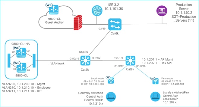
In some use-cases, inline tagging is enabled on the C9800 uplink interface to the interconnected Cat9k switch. As stated previously, inline tagging allows the source SGT to be inserted into the Cisco Meta-Data (CMD) field of the L2 frames of every packet transmitted. If the C9800 uplink interface is configured to use inline tagging, then the interface on the interconnected device must also have inline tagging enabled (Cat9k on the left, interface G1/0/15 in this topology). If another device were inserted between the C9800 and Cat9k (a firewall for example), then the connected interfaces on that FW must also support inline tagging.
The same is true for the connectivity between the AP’s and their interconnected Cat9k, some use-cases enable inline tagging here in flexconnect mode.
In this guide, the C9800 Cloud version (C9800-CL) is mostly used, and the Gigabit Ethernet 2 (G2) is configured as the uplink interface. Of course, customers may use a port-channel or any other uplink interfaces available on the virtual or physical appliances. The following shows a trunk deployed on the uplink interface:
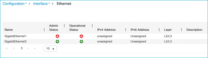
GigabitEthernet2 details:
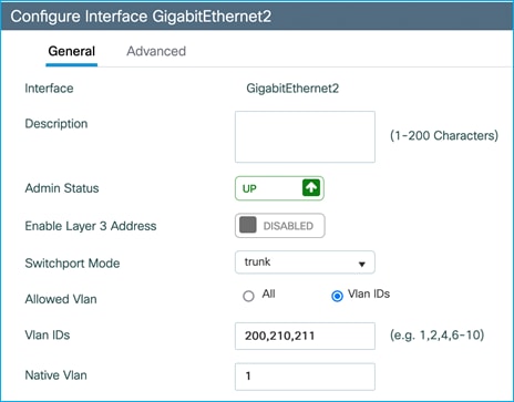
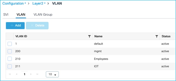
VLANs added:
VLAN 200 used for Management
VLAN 210 used for Employees
VLAN 211 used for IOT
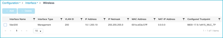
Wireless Management Interface:
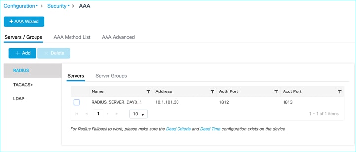
AAA Configuration:
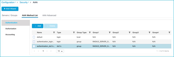
AAA Method List > Authentication:
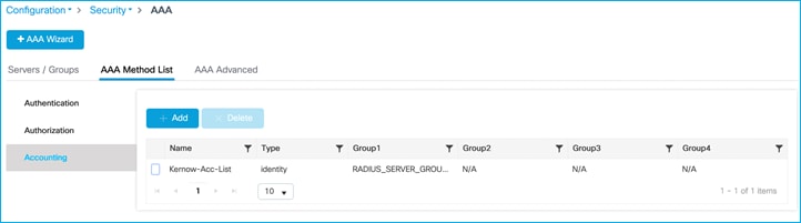
AAA Method List > Accounting:
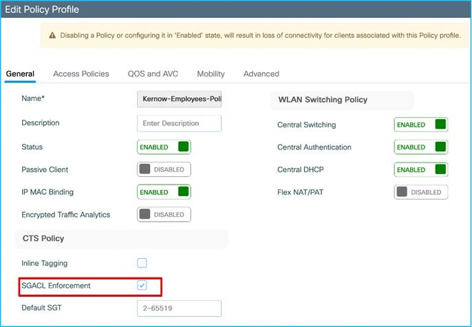
The initial stage of this guide covers the case where there is no inline tagging or SGACL enforcement set on the Policy Profiles. These options are explained and set when appropriate later in the guide.
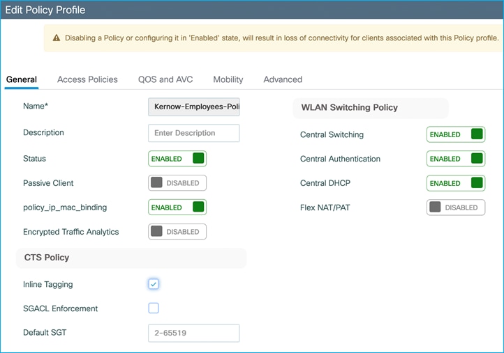
An example policy profile General tab follows for the Employees for central switching:
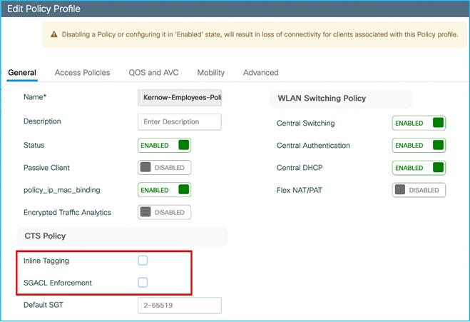
Note: For the equivalent policy profile for FlexConnect local switching deployment, both Central Switching and Central DHCP are disabled.
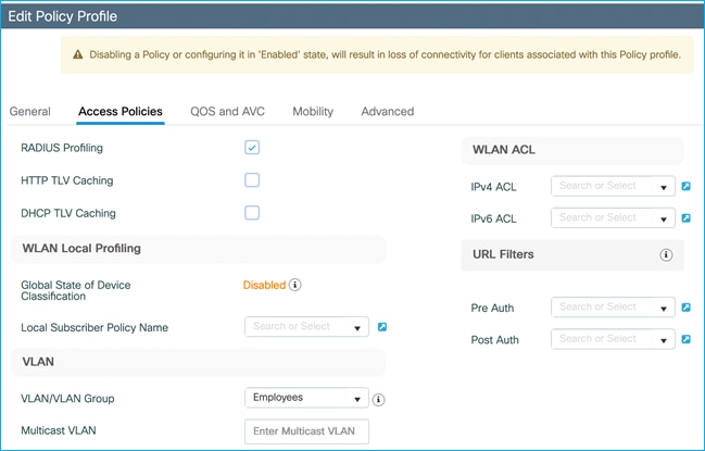
The Employees VLAN is defined within the Access Policies tab of the Employees Policy Profile, along with enabling RADIUS Profiling.
Configuration > Tags & Profiles > Policy > Employees Policy profile > Access Policies:
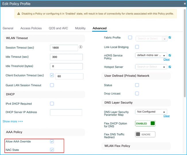
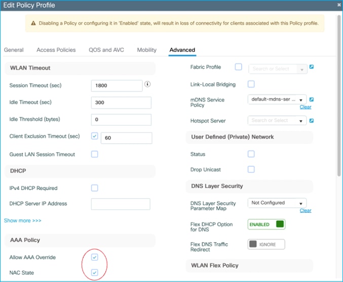
Configuration > Tags & Profiles > Policy > Employees Policy profile > Advanced has AAA override and NAC state enabled, this is to successfully receive the SGT assigned by ISE in the Authorization Reply:
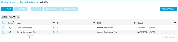
WLANs are setup and ready for Employees for use in central switching mode as well as FlexConnect local switching:
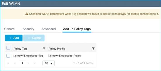
WLAN ‘Add to Policy Tags’ tab, links the Policy Tag with the Policy Profile:
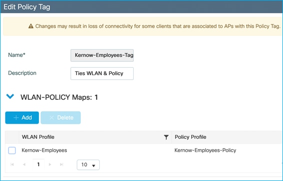
Under Configuration > Tags & Profiles > Tags, Policy Tag links WLAN Profile with Policy Profile:
Under Configuration > Tags & Profiles > Tags, the APs are statically assigned to the appropriate Policy Tag (Site Tag becomes more relevant for SGT purposes in Flex mode):
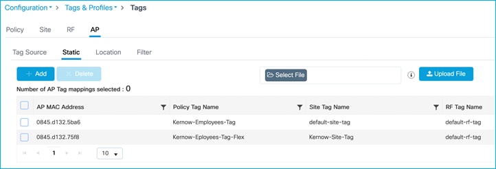
Note: RF tags and Site tags for central mode use the default tags, but in a live deployment these would be leveraged as per your design.
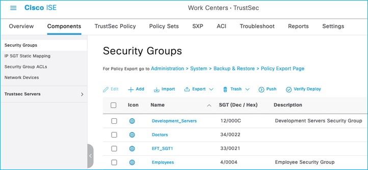
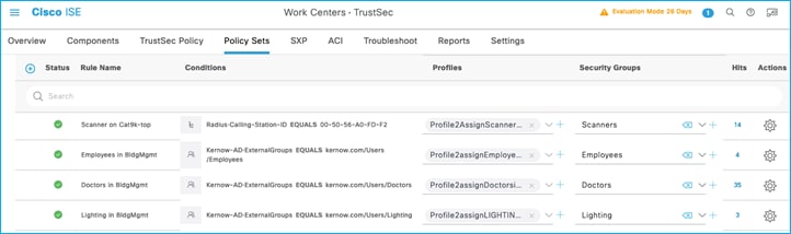
ISE has SGTs, SGACLs, Policies and C9800 Network Device entries already added and Authorization Rules already setup:
SGTs:
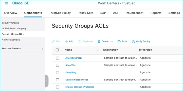
Security Group ACLs (SGACLs):
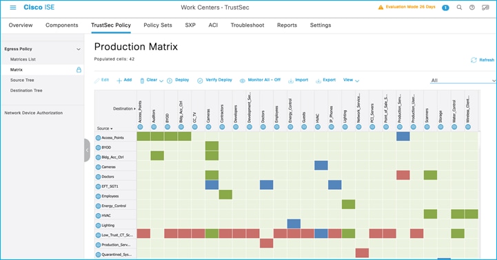
Policy Matrix (some changes are implemented within the document):
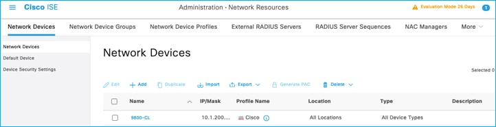
Network Devices:
Authorization Rules:
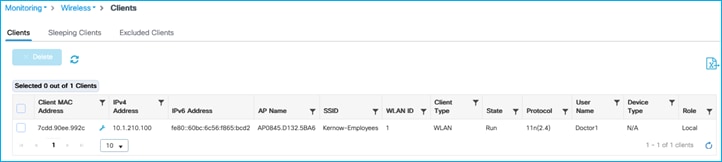
Dynamically Assigning SGT to Wireless Client from ISE (Without CTS Provisioning/C9800 Enrollment)
This use-case is to show an SGT can dynamically be assigned from ISE to a wireless client without the C9800 controller first having to go through CTS provisioning and device enrollment. This CTS provisioning and device enrollment is where the network device itself authenticates with ISE and downloads a protected access credential (PAC) and the environment-data containing the SGTs, TrustSec server list, Network Device SGT and timers. This allows the C9800 to enforce policy. So, without the C9800 controller being setup to download this TrustSec enrollment information, connect and authenticate a wireless client and assign an SGT from ISE authorization:
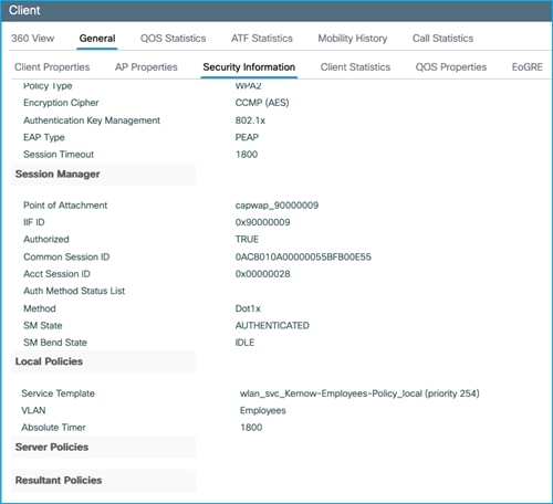
To ensure the C9800 controller accepts the assigned SGT from ISE within the authorization reply, enable both ‘Allow AAA Override’ and ‘NAC State’ within the used Policy Profile (Advanced Tab) on the C9800:
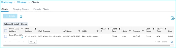
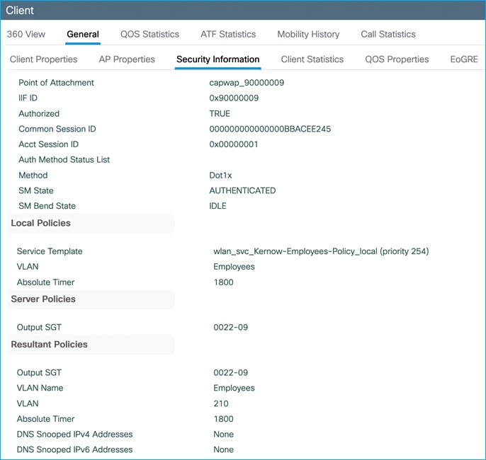
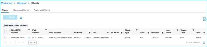
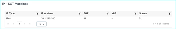
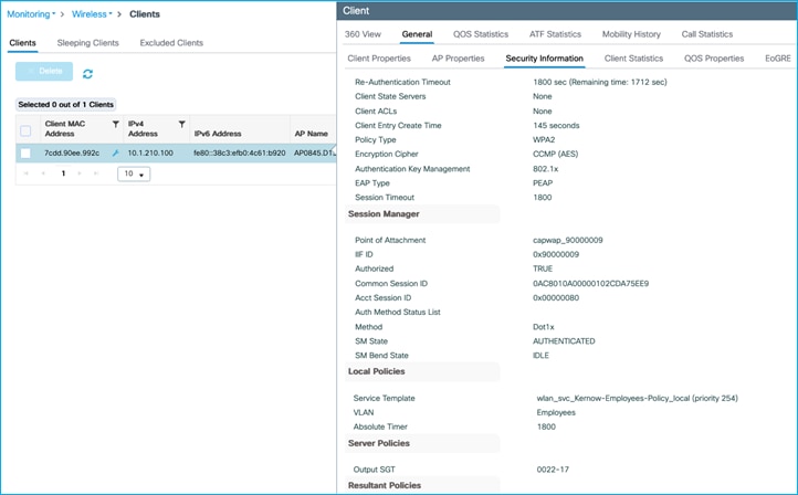
The assigned SGT can be seen in the C9800 controller under Client details > General > Security Information (see ‘Output SGT’ in the capture below), and this example shows SGT for Doctors, number of 22 (this is HEX i.e., decimal is 34):
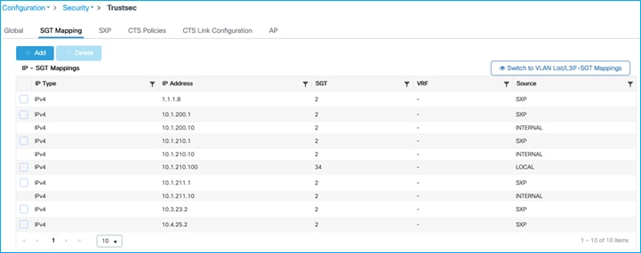
The mapping also appears under Monitoring > General > TrustSec, where it’s shown in decimal format:
So, without CTS Provisioning and Network Device Enrollment, an SGT can still be assigned to wireless clients and used to classify wireless traffic. Subsequently, that classification can be sent off-platform for enforcement elsewhere.
It is best practice to only configure or enable functions if needed. There is no need to enable full CTS Provisioning and Network Device Enrollment if it is not required (for example, if enforcing off-platform).
C9800 Propagating Client SGT and Enforcing Off-Platform (Without CTS Provisioning/C9800 Enrollment)
Propagating Using SXP and Enforcing Off-Platform
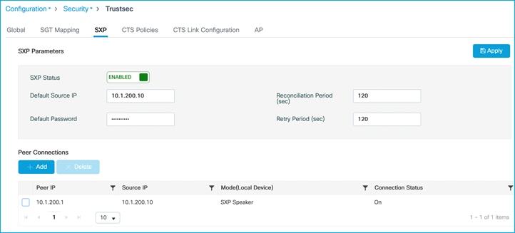
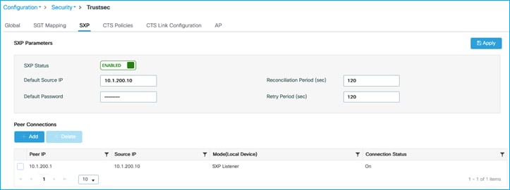
Add SXP default parameters and SXP connection on C9800 (to Cat9k) to see if we can enforce from wireless endpoint to wired on the adjacent Cat9k:
Note: There is no support of IPv6 based peer SXP connections (but the IPv4 based connections do support the propagation of IPv6 SGT bindings).
Configure the Cat9k end to match:
Kernow-Cat9300-b#show run | inc sxp
cts sxp enable
cts sxp default source-ip 10.1.200.1
cts sxp default password <pwd>
cts sxp connection peer 10.1.200.10 password default mode local listener hold-time 0 0
Show the state of the SXP connection on the Cat9k to see it’s up/On:
Kernow-Cat9300-b#show cts sxp connections brief
SXP : Enabled
Highest Version Supported: 5
Default Password : Set
Default Key-Chain: Not Set
Default Key-Chain Name: Not Applicable
Default Source IP: 10.1.200.1
Connection retry open period: 120 secs
Reconcile period: 120 secs
Retry open timer is not running
Peer-Sequence traverse limit for export: Not Set
Peer-Sequence traverse limit for import: Not Set
----------------------------------------------------------------------------------------
Peer_IP Source_IP Conn Status Duration
----------------------------------------------------------------------------------------
10.1.200.10 10.1.200.1 On 0:00:02:47 (dd:hr:mm:sec)
Total num of SXP Connections = 1
Cat9k receives the mapping from the C9800 via SXP ok. Have also added a static mapping for a DC server in the Cat9k:
cts role-based sgt-map 10.1.140.2 sgt 11 (where SGT 11 is production_servers):
Kernow-Cat9300-b#show cts role-based sgt-map all
Active IPv4-SGT Bindings Information
IP Address SGT Source
============================================
1.1.1.8 2 INTERNAL
10.1.140.2 11 CLI <-Added via CLI
10.1.200.1 2 INTERNAL
10.1.210.1 2 INTERNAL
10.1.210.100 34 SXP <-From C9800 for wireless client
10.1.211.1 2 INTERNAL
10.3.23.2 2 INTERNAL
10.4.25.2 2 INTERNAL
IP-SGT Active Bindings Summary
============================================
Total number of CLI bindings = 1
Total number of SXP bindings = 1
Total number of INTERNAL bindings = 6
Total number of active bindings = 8
Active IPv6-SGT Bindings Information
IP Address SGT Source
================================================================
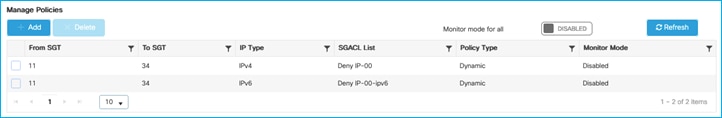
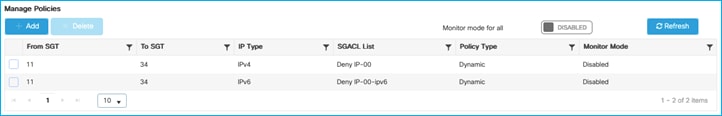
Added policy in ISE to deny traffic from Doctors SGT 34 to Production_Servers SGT 11:
The policy is retrieved by the Cat9k:
Kernow-Cat9300-b#show cts role-based permissions from 34
IPv4 Role-based permissions from group 34:Doctors to group 11:Production_Servers:
Deny IP-00
RBACL Monitor All for Dynamic Policies : FALSE
RBACL Monitor All for Configured Policies : FALSE
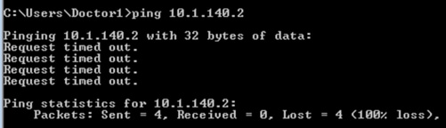
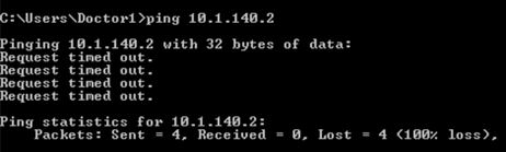
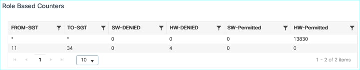
Ping is denied from wireless client to the Production Server:
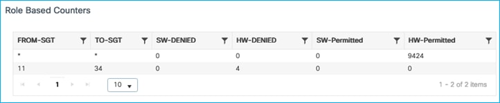
The enforcement can be seen to be carried out on the Cat9k switch:
Kernow-Cat9300-b#show cts role-based counters from 34
Role-based IPv4 counters
From To SW-Denied HW-Denied SW-Permitt HW-Permitt SW-Monitor HW-Monitor
34 11 0 4 0 0 0 0
So, the C9800 propagates dynamic IP:SGT mappings via SXP to be enforced elsewhere.
A general rule-of-thumb or best practice is to use inline tagging where you can and SXP where you need to. Inline tagging operates at line rate and the SGT is handled in the data-plane without the need for extra control-plane mechanisms.
SXP Filters when Sending Off-Platform
Sometimes it may not be necessary to send all SXP mappings from the C9800 to another device. SXP filters exist to reduce the number of mappings sent, see the examples below. The SXP filters are supported only using the CLI, not the GUI/webui today.
C9800 setup with an SXP connection, sending mappings to north-bound Cat9k:
Move the static mapping for the DC server added in the previous use-case from the Cat9k to the C9800. This is so that the Cat9k learns of this mapping via SXP from the C9800:
On the Cat9k: no cts role-based sgt-map 10.1.140.2 sgt 11 (where SGT 11 is production_servers).
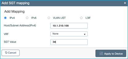
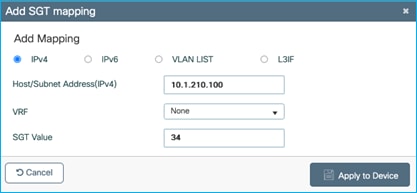
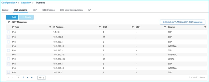
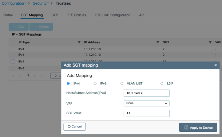
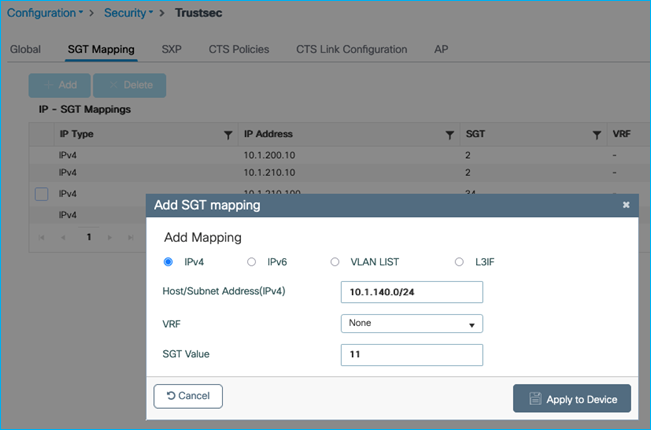
On the C9800 at Configuration > Security > TrustSec > SGT Mapping, select Add and enter the following IP and SGT Value for adding an IPv4 static mapping:
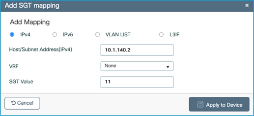
Select ‘Apply to Device’.
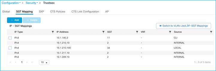
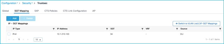
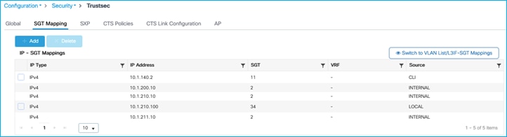
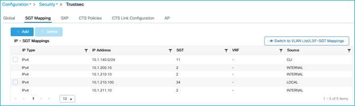
Current IP:SGT mappings on the C9800:
The Cat9k is the receiving end of this SXP connection and SXP mappings:
Kernow-Cat9300-b#show cts sxp connections brief
SXP : Enabled
Highest Version Supported: 5
Default Password : Set
Default Key-Chain: Not Set
Default Key-Chain Name: Not Applicable
Default Source IP: 1.1.1.8
Connection retry open period: 120 secs
Reconcile period: 120 secs
Retry open timer is not running
Peer-Sequence traverse limit for export: Not Set
Peer-Sequence traverse limit for import: Not Set
----------------------------------------------------------------------------------------------------------------------------------
Peer_IP Source_IP Conn Status Duration
----------------------------------------------------------------------------------------------------------------------------------
10.1.200.10 10.1.200.1 On 0:00:03:20 (dd:hr:mm:sec)
Total num of SXP Connections = 1
Kernow-Cat9300-b#show cts role-based sgt-map all
Active IPv4-SGT Bindings Information
IP Address SGT Source
============================================
1.1.1.8 2 INTERNAL
10.1.140.2 11 SXP
10.1.200.1 2 INTERNAL
10.1.210.1 2 INTERNAL
10.1.210.10 2 SXP
10.1.210.100 34 SXP
10.1.211.1 2 INTERNAL
10.1.211.10 2 SXP
10.1.249.10 2 SXP
10.3.23.2 2 INTERNAL
10.4.25.2 2 INTERNAL
10.6.50.100 28 LOCAL
10.6.50.254 2 INTERNAL
IP-SGT Active Bindings Summary
============================================
Total number of SXP bindings = 5
Total number of LOCAL bindings = 1
Total number of INTERNAL bindings = 7
Total number of active bindings = 13
Active IPv6-SGT Bindings Information
IP Address SGT Source
================================================================
The following is building an SXP filter to stop sending SGT 2 (should stop sending 10.1.210.10, 10.1.211.10 and 10.1.249.10):
cts sxp filter-enable
!
cts sxp filter-list block-sgt2
deny sgt 2
permit sgt all <-This is the default rule (otherwise denied)
!
cts sxp filter-group speaker speaker-to-Cat9k
filter block-sgt2
peer ipv4 10.1.200.1
Command to show the configuration along with filter hit counts:
9800-17.9.1#show cts sxp filter-group speaker detailed
Global Speaker Filter: Not configured
Filter-group: speaker-to-Cat9k
Filter-name: block-sgt2
Filter-rules:
10 deny sgt 2 (0)
20 permit sgt all (0)
Total Matches: 0
Default Deny Count: 0
peer 10.1.200.1
On the C9800, carry out a ‘no cts sxp enable’ and then ‘cts sxp enable’ to refresh the table, result is the C9800 filter has denied 3 mappings from being sent to the Cat9k and permitted 2 mappings:
9800-17.9.1#show cts sxp filter-group speaker detailed
Global Speaker Filter: Not configured
Filter-group: speaker-to-Cat9k
Filter-name: block-sgt2
Filter-rules:
10 deny sgt 2 (3)
20 permit sgt all (2)
Total Matches: 5
Default Deny Count: 0
peer 10.1.200.1
The Cat9k shows the new set of mappings i.e. only 2 mappings have been received from the C9800:
Kernow-Cat9300-b#show cts role-based sgt-map all
Active IPv4-SGT Bindings Information
IP Address SGT Source
============================================
1.1.1.8 2 INTERNAL
10.1.140.2 11 SXP
10.1.200.1 2 INTERNAL
10.1.210.1 2 INTERNAL
10.1.210.100 34 SXP
10.1.211.1 2 INTERNAL
10.3.23.2 2 INTERNAL
10.4.25.2 2 INTERNAL
10.6.50.100 28 LOCAL
10.6.50.254 2 INTERNAL
IP-SGT Active Bindings Summary
============================================
Total number of SXP bindings = 2
Total number of LOCAL bindings = 1
Total number of INTERNAL bindings = 7
Total number of active bindings = 10
Active IPv6-SGT Bindings Information
IP Address SGT Source
================================================================
The filter-list can include multiple entries and if a prefix plus an SGT are entered on the same entry then the operation is an OR:
cts sxp filter-enable
!
cts sxp filter-list block-prefix-OR-sgt
deny ipv4 10.1.140.0/24 deny sgt 2
permit sgt all
!
cts sxp filter-group speaker speaker-to-Cat9k
filter block-prefix-OR-sgt
peer ipv4 10.1.200.1
Taking the following mapping list on the C9800:
9800-17.9.1#show cts role-based sgt-map all
Active IPv4-SGT Bindings Information
IP Address SGT Source
============================================
10.1.140.2 11 CLI
10.1.210.10 2 INTERNAL
10.1.210.100 34 LOCAL
10.1.211.10 2 INTERNAL
10.1.249.10 2 INTERNAL
After the filter, the receiving Cat9k shows just the 1 entry learned from the C9800 over SXP (after blocking entries with prefix 10.1.140.0/24 OR SGT 2):
Kernow-Cat9300-b#show cts role-based sgt-map all
Active IPv4-SGT Bindings Information
IP Address SGT Source
============================================
1.1.1.8 2 INTERNAL
10.1.200.1 2 INTERNAL
10.1.210.1 2 INTERNAL
10.1.210.100 34 SXP
10.1.211.1 2 INTERNAL
10.3.23.2 2 INTERNAL
10.4.25.2 2 INTERNAL
10.6.50.100 28 LOCAL
10.6.50.254 2 INTERNAL
The conclusion is that SXP filtering works successfully when propagating mappings off-platform.
Propagating Using Inline Tagging (CMD) and Enforcing Off-Platform
We will show here that the client SGT can also be propagated via inline tagging for enforcement off-platform.
It would be best practice to utilize inline tagging over SXP in situations where it is supported.
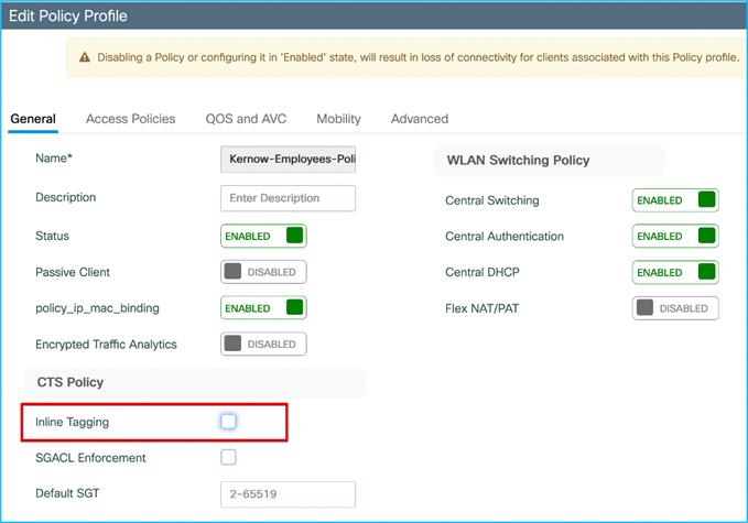
Set inline tagging on C9800 first before setting it on the adjacent Cat9k interface. (We will set inline tagging on the policy profile first and prove later that this setting is in fact not used as it is the setting on the uplink which is actually used):
Inline tagging is enabled on the policy profile (seen via CLI) but not currently on the uplink G2:
wireless profile policy Kernow-Employees-Policy
aaa-override
accounting-list Kernow-Acc-List
cts inline-tagging
nac
radius-profiling
vlan Employees
no shutdown
!
interface GigabitEthernet2
switchport trunk allowed vlan 200,210,211
switchport mode trunk
switchport nonegotiate
negotiation auto
no mop enabled
no mop sysid
end
Using monitor capture on the receiving Cat9k interface, we can see there is no CMD sent by the C9800:
Ethernet II, Src: 7c:dd:90:ee:99:2c (7c:dd:90:ee:99:2c), Dst: 04:6c:9d:1f:e3:f1 (04:6c:9d:1f:e3:f1)
Destination: 04:6c:9d:1f:e3:f1 (04:6c:9d:1f:e3:f1)
Address: 04:6c:9d:1f:e3:f1 (04:6c:9d:1f:e3:f1)
.... ..0. .... .... .... .... = LG bit: Globally unique address (factory default)
.... ...0 .... .... .... .... = IG bit: Individual address (unicast)
Source: 7c:dd:90:ee:99:2c (7c:dd:90:ee:99:2c)
Address: 7c:dd:90:ee:99:2c (7c:dd:90:ee:99:2c)
.... ..0. .... .... .... .... = LG bit: Globally unique address (factory default)
.... ...0 .... .... .... .... = IG bit: Individual address (unicast)
Type: 802.1Q Virtual LAN (0x8100)
802.1Q Virtual LAN, PRI: 0, DEI: 0, ID: 210
000. .... .... .... = Priority: Best Effort (default) (0)
...0 .... .... .... = DEI: Ineligible
.... 0000 1101 0010 = ID: 210 <-Cisco MetaData with SGT would be shown here
Type: IPv4 (0x0800)
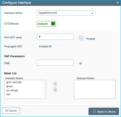
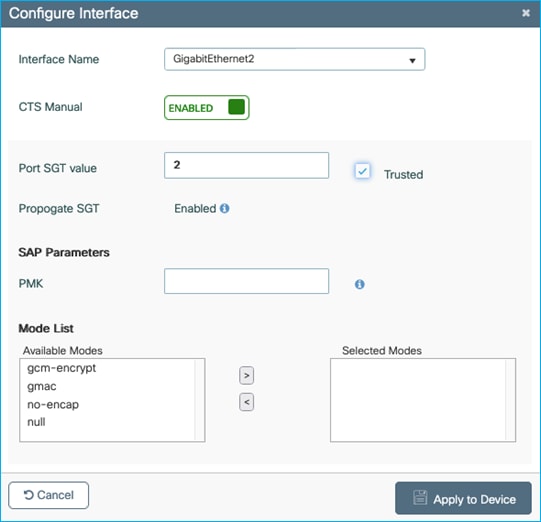
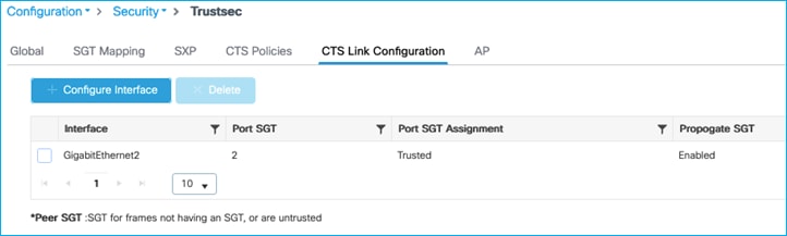
So, we have to enable CMD on the uplink interface (GigabitEthernet 2 in this example), under Configuration > Security > TrustSec > CTS Link Configuration:
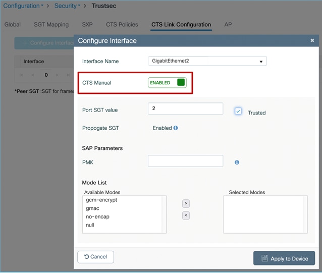
Note: It is best practice to assign TrustSec_Devices SGT 2 to network devices. Initial ISE configuration comes with TrustSec_Devices SGT 2 pre-added and assigned in the default rule of the Network Device Authorization table under Work Centers > TrustSec > TrustSec Policy > Network Device Authorization.
Note: SGT 2 within the ‘Port SGT value’ within the screen capture above, will be used in conjunction with the Trusted option as follows.
Note: If Trusted is not selected, then under the ‘cts manual’ configuration will be seen ‘policy static sgt 2’. In this case, all traffic being received by the C9800 controller on this interface will not be trusted and will be classified with SGT 2.
Note: If Trusted is selected, then under the ‘cts manual’ configuration will be seen ‘policy static sgt 2 trusted’. In this case, if there is no SGT in the CMD field being received, then classify the receiving traffic with SGT 2. In the case where the uplink is connected to a Cat9k, the Cat9k will always either send the assigned SGT of that traffic, or SGT 0/Unknown, both of which will be trusted by the C9800 controller. In this scenario, you will never see SGT 2 being assigned.
Once applied:
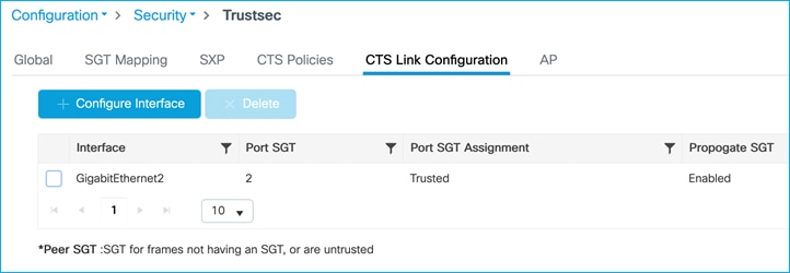
When applied, the inline tagging configuration can be seen to be implemented by checking CLI:
interface GigabitEthernet2
switchport trunk allowed vlan 200,210,211
switchport mode trunk
switchport nonegotiate
negotiation auto
cts manual
policy static sgt 2 trusted
no mop enabled
no mop sysid
end
Now, manually set inline tagging on the Cat9k end of the link (shut / no shut is not required for a Cat9k):
interface GigabitEthernet1/0/15
switchport trunk allowed vlan 200,210,211
switchport mode trunk
switchport nonegotiate
cts manual
policy static sgt 2 trusted
ip dhcp snooping trust
end
Using ‘monitor capture’ on the Cat9k G1/0/15 interface, it can be seen that SGT 34 is seen entering the Cat9k from the C9800 for traffic from the wireless client:
Ethernet II, Src: 7c:dd:90:ee:99:2c (7c:dd:90:ee:99:2c), Dst: 04:6c:9d:1f:e3:f1 (04:6c:9d:1f:e3:f1)
Destination: 04:6c:9d:1f:e3:f1 (04:6c:9d:1f:e3:f1)
Address: 04:6c:9d:1f:e3:f1 (04:6c:9d:1f:e3:f1)
.... ..0. .... .... .... .... = LG bit: Globally unique address (factory default)
.... ...0 .... .... .... .... = IG bit: Individual address (unicast)
Source: 7c:dd:90:ee:99:2c (7c:dd:90:ee:99:2c)
Address: 7c:dd:90:ee:99:2c (7c:dd:90:ee:99:2c)
.... ..0. .... .... .... .... = LG bit: Globally unique address (factory default)
.... ...0 .... .... .... .... = IG bit: Individual address (unicast)
Type: 802.1Q Virtual LAN (0x8100)
802.1Q Virtual LAN, PRI: 0, DEI: 0, ID: 210
000. .... .... .... = Priority: Best Effort (default) (0)
...0 .... .... .... = DEI: Ineligible
.... 0000 1101 0010 = ID: 210
Type: CiscoMetaData (0x8909)
Cisco MetaData
Version: 1
Length: 1
Options: 0x0001
SGT: 34
Type: IPv4 (0x0800)
And this is enforced on the Cat9k:
Kernow-Cat9300-b#show cts role-based permissions from 34
IPv4 Role-based permissions from group 34:Doctors to group 11:Production_Servers:
Deny IP-00
RBACL Monitor All for Dynamic Policies : FALSE
RBACL Monitor All for Configured Policies : FALSE
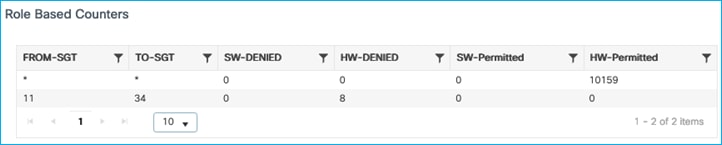
Kernow-Cat9300-b#show cts role-based counters from 34
Role-based IPv4 counters
From To SW-Denied HW-Denied SW-Permitt HW-Permitt SW-Monitor HW-Monitor
34 11 0 8 0 0 0 0
Note: When using ‘monitor capture’ on the C9k platforms to investigate inline tagging, the SGT is inserted on the wire after the monitor samples the traffic. This means that the inserted SGT will not be shown for traffic egressing the platform. It is best practice to use ‘monitor capture’ on the receiving device in order to see the SGT which was propagated on the wire.
Now, what happens if inline tagging is disabled from the policy profile?
Inline is removed from the policy profile, as expected:
wireless profile policy Kernow-Employees-Policy
aaa-override
accounting-list Kernow-Acc-List
nac
radius-profiling
vlan Employees
no shutdown
But the client SGT is still propagated via inline tagging (CMD) to the Cat9k:
Ethernet II, Src: 7c:dd:90:ee:99:2c (7c:dd:90:ee:99:2c), Dst: 04:6c:9d:1f:e3:f1 (04:6c:9d:1f:e3:f1)
Destination: 04:6c:9d:1f:e3:f1 (04:6c:9d:1f:e3:f1)
Address: 04:6c:9d:1f:e3:f1 (04:6c:9d:1f:e3:f1)
.... ..0. .... .... .... .... = LG bit: Globally unique address (factory default)
.... ...0 .... .... .... .... = IG bit: Individual address (unicast)
Source: 7c:dd:90:ee:99:2c (7c:dd:90:ee:99:2c)
Address: 7c:dd:90:ee:99:2c (7c:dd:90:ee:99:2c)
.... ..0. .... .... .... .... = LG bit: Globally unique address (factory default)
.... ...0 .... .... .... .... = IG bit: Individual address (unicast)
Type: 802.1Q Virtual LAN (0x8100)
802.1Q Virtual LAN, PRI: 0, DEI: 0, ID: 210
000. .... .... .... = Priority: Best Effort (default) (0)
...0 .... .... .... = DEI: Ineligible
.... 0000 1101 0010 = ID: 210
Type: CiscoMetaData (0x8909)
Cisco MetaData
Version: 1
Length: 1
Options: 0x0001
SGT: 34
Type: IPv4 (0x0800)
And it's still being enforced on the Cat9k:
Kernow-Cat9300-b#sh cts role counters from 34
Role-based IPv4 counters
From To SW-Denied HW-Denied SW-Permitt HW-Permitt SW-Monitor HW-Monitor
34 11 0 12 0 0 0 0
The setting of inline tagging on the policy profile is currently not used for this use-case, the SGT is propagated if set on the uplink interface. The use of the inline tagging setting on the policy profile will be introduced in a future release.
C9800 Static IP:SGT sent via SXP and Enforcing Off-Platform
Remove inline tagging from C9800 to Cat9k in case that interferes with the results. Remove ‘cts manual’ config from Cat9k interface G1/0/15 and remove inline tagging from C9800 G2.
Check SXP default parameters and SXP connection from C9800 to Cat9k. On C9800, navigate to Configuration > Security > TrustSec > SXP:

Connection of ‘Off’ as seen above, so check and re-enable SXP on the Cat9k peer:
Kernow-Cat9300-b#conf t
Enter configuration commands, one per line. End with CNTL/Z.
Kernow-Cat9300-b(config)#cts sxp enable
Kernow-Cat9300-b(config)#cts sxp default source-ip 10.1.200.1
Kernow-Cat9300-b(config)#cts sxp default password xxx
Kernow-Cat9300-b(config)#cts sxp connection peer 10.1.200.10 password default mode local listener
Kernow-Cat9300-b#show cts sxp connections brief
SXP : Enabled
Highest Version Supported: 5
Default Password : Set
Default Key-Chain: Not Set
Default Key-Chain Name: Not Applicable
Default Source IP: 10.1.200.1
Connection retry open period: 120 secs
Reconcile period: 120 secs
Retry open timer is not running
Peer-Sequence traverse limit for export: Not Set
Peer-Sequence traverse limit for import: Not Set
----------------------------------------------------------------------------------------
Peer_IP Source_IP Conn Status Duration
----------------------------------------------------------------------------------------
10.1.200.10 10.1.200.1 On 0:00:00:59 (dd:hr:mm:sec)
Total num of SXP Connections = 1
C9800 now shows SXP connection as On:

Connect wireless client and do not assign an SGT from ISE:
No dynamic IP:SGT mapping exists (Monitoring > General > TrustSec):
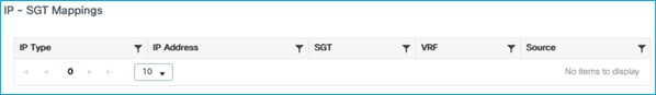
Add a static IPv4:SGT mapping in the C9800 under Configuration > Security > TrustSec > SGT Mapping. Click Add:
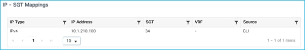
This is applied successfully:

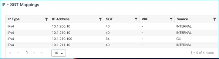
Also seen under Monitoring > General > TrustSec:
Check on the Ca9k whether this mapping has been received from the C9800 via SXP. It has:
Kernow-Cat9300-b#show cts role-based sgt-map all
Active IPv4-SGT Bindings Information
IP Address SGT Source
============================================
1.1.1.8 2 INTERNAL
10.1.140.2 11 CLI
10.1.200.1 2 INTERNAL
10.1.210.1 2 INTERNAL
10.1.210.100 34 SXP
10.1.211.1 2 INTERNAL
10.3.23.2 2 INTERNAL
10.4.25.2 2 INTERNAL
IP-SGT Active Bindings Summary
============================================
Total number of CLI bindings = 1
Total number of SXP bindings = 1
Total number of INTERNAL bindings = 6
Total number of active bindings = 8
Active IPv6-SGT Bindings Information
IP Address SGT Source
================================================================
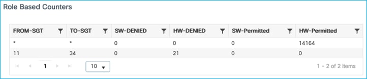
Traffic from the wireless client to the Production Server is enforced successfully on the Cat9k due to this SXP mapping learned as a source from the C9800 and the destination mapping of the production server still being present from a previous use-case:
Kernow-Cat9300-b#show cts role-based permissions from 34
IPv4 Role-based permissions from group 34:Doctors to group 11:Production_Servers:
Deny IP-00
RBACL Monitor All for Dynamic Policies : FALSE
RBACL Monitor All for Configured Policies : FALSE
Kernow-Cat9300-b#show cts role-based counters from 34
Role-based IPv4 counters
From To SW-Denied HW-Denied SW-Permitt HW-Permitt SW-Monitor HW-Monitor
34 11 0 28 0 0 0 0
So, an added static IP:SGT mapping on the C9800 does successfully get propagated via SXP to a northbound platform. However, you have to question the usefulness of this function. Why not just add the static mapping on the destination platform instead of using SXP from the C9800? Or how about using SXP from another device like ISE for example. It is good that the function works but it has limited practicality.
C9800 Static IP:SGT sent via Inline CMD and Enforcing Off-Platform (Not Supported)
If no SGT is dynamically assigned by ISE to a wireless client, statically assign an SGT to the IP of a wireless client and propagate it via CMD to another platform for enforcement. This is a capability supported by other types of network devices.
Ensure inline is set on the C9800 G2 interface – Navigate to Configuration > Security > TrustSec > CTS Link Configuration to configure the interface:
Also set inline tagging on the peer Cat9k interface G1/0/15:
interface GigabitEthernet1/0/15
switchport trunk allowed vlan 200,210,211
switchport mode trunk
switchport nonegotiate
cts manual
policy static sgt 2 trusted
ip dhcp snooping trust
end
Authenticate wireless client but do not assign an SGT from ISE:
There’s no SGT assigned, as seen at the bottom of the following screen i.e. Server Policies is blank:
Additionally, Monitoring > General > TrustSec on the C9800 shows no IP – SGT mappings:

Now, we’ll set a static entry to assign SGT Doctors/34 to the client IP of 10.1.210.100. Navigate to Configuration > Security > TrustSec > SGT Mapping to add a new IPv4 entry:
Once applied:
Can also be seen via Monitoring > General > TrustSec
When client traffic flows from C9800 to the Cat9k, the statically assigned SGT of 34 is NOT propagated to the Cat9k, as seen using a ‘monitor capture’ command on the Cat9k G1/0/15 interface:
Ethernet II, Src: 7c:dd:90:ee:99:2c (7c:dd:90:ee:99:2c), Dst: 04:6c:9d:1f:e3:f1 (04:6c:9d:1f:e3:f1)
Destination: 04:6c:9d:1f:e3:f1 (04:6c:9d:1f:e3:f1)
Address: 04:6c:9d:1f:e3:f1 (04:6c:9d:1f:e3:f1)
.... ..0. .... .... .... .... = LG bit: Globally unique address (factory default)
.... ...0 .... .... .... .... = IG bit: Individual address (unicast)
Source: 7c:dd:90:ee:99:2c (7c:dd:90:ee:99:2c)
Address: 7c:dd:90:ee:99:2c (7c:dd:90:ee:99:2c)
.... ..0. .... .... .... .... = LG bit: Globally unique address (factory default)
.... ...0 .... .... .... .... = IG bit: Individual address (unicast)
Type: 802.1Q Virtual LAN (0x8100)
802.1Q Virtual LAN, PRI: 0, DEI: 0, ID: 210
000. .... .... .... = Priority: Best Effort (default) (0)
...0 .... .... .... = DEI: Ineligible
.... 0000 1101 0010 = ID: 210
Type: CiscoMetaData (0x8909)
Cisco MetaData
Version: 1
Length: 1
Options: 0x0001
SGT: 0
Type: IPv4 (0x0800)
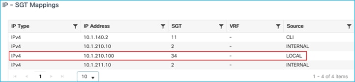
Assign an SGT dynamically from ISE (just as a test); Update ISE authz rule to assign SGT 34 and re-auth the client. The dynamic SGT assigned (source as LOCAL in the table below) takes precedence over the static entry sourced from CLI:
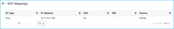
SGT is sent to Cat9k in CMD field with the assigned dynamic SGT entry (source: LOCAL):
Ethernet II, Src: 7c:dd:90:ee:99:2c (7c:dd:90:ee:99:2c), Dst: 04:6c:9d:1f:e3:f1 (04:6c:9d:1f:e3:f1)
Destination: 04:6c:9d:1f:e3:f1 (04:6c:9d:1f:e3:f1)
Address: 04:6c:9d:1f:e3:f1 (04:6c:9d:1f:e3:f1)
.... ..0. .... .... .... .... = LG bit: Globally unique address (factory default)
.... ...0 .... .... .... .... = IG bit: Individual address (unicast)
Source: 7c:dd:90:ee:99:2c (7c:dd:90:ee:99:2c)
Address: 7c:dd:90:ee:99:2c (7c:dd:90:ee:99:2c)
.... ..0. .... .... .... .... = LG bit: Globally unique address (factory default)
.... ...0 .... .... .... .... = IG bit: Individual address (unicast)
Type: 802.1Q Virtual LAN (0x8100)
802.1Q Virtual LAN, PRI: 0, DEI: 0, ID: 210
000. .... .... .... = Priority: Best Effort (default) (0)
...0 .... .... .... = DEI: Ineligible
.... 0000 1101 0010 = ID: 210
Type: CiscoMetaData (0x8909)
Cisco MetaData
Version: 1
Length: 1
Options: 0x0001
SGT: 34
Type: IPv4 (0x0800)
Again, remove dynamic SGT assignment from ISE leaving only the static entry:
SGT received by the Cat9k is again 0 (not 34):
Ethernet II, Src: 7c:dd:90:ee:99:2c (7c:dd:90:ee:99:2c), Dst: 04:6c:9d:1f:e3:f1 (04:6c:9d:1f:e3:f1)
Destination: 04:6c:9d:1f:e3:f1 (04:6c:9d:1f:e3:f1)
Address: 04:6c:9d:1f:e3:f1 (04:6c:9d:1f:e3:f1)
.... ..0. .... .... .... .... = LG bit: Globally unique address (factory default)
.... ...0 .... .... .... .... = IG bit: Individual address (unicast)
Source: 7c:dd:90:ee:99:2c (7c:dd:90:ee:99:2c)
Address: 7c:dd:90:ee:99:2c (7c:dd:90:ee:99:2c)
.... ..0. .... .... .... .... = LG bit: Globally unique address (factory default)
.... ...0 .... .... .... .... = IG bit: Individual address (unicast)
Type: 802.1Q Virtual LAN (0x8100)
802.1Q Virtual LAN, PRI: 0, DEI: 0, ID: 210
000. .... .... .... = Priority: Best Effort (default) (0)
...0 .... .... .... = DEI: Ineligible
.... 0000 1101 0010 = ID: 210
Type: CiscoMetaData (0x8909)
Cisco MetaData
Version: 1
Length: 1
Options: 0x0001
SGT: 0
Type: IPv4 (0x0800)
A DDTS has been opened for this use-case: CSCwd06879 C9800 wireless static IP to SGT mapping not inline tagged over uplink.
C9800 Default SGT Assigned via Policy Profile and Enforcing Off-Platform
The previous two use-cases covered static assignment of the IP:SGT on the C9800 and sending off-platform to be enforced elsewhere. There is another way to statically assign a default SGT to a wireless client and that is provided through the policy profile. Of course, all endpoints using that Policy Profile will be subject to being assigned that same SGT. If a wireless client is authenticated and dynamically assigned an SGT from ISE, then that will take precedence over the static/default assignment on the policy profile.
Set the ‘Default SGT’ on the policy profile to be 3 as an example:
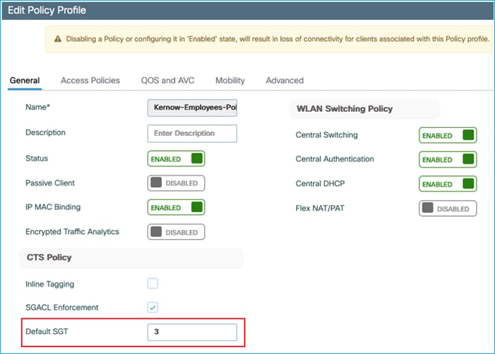
Now, authenticate a wireless client but configure the ISE authorization policy to not assign an SGT.
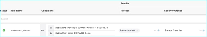
The client on the C9800 shows up as having the Default SGT assigned as configured in the Policy Profile. Navigate to Monitoring > Wireless > Clients > Select Client > General > Security Information, scroll down to see the two Output SGT entries:
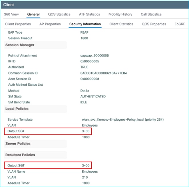
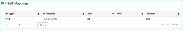
This assignment shows up under Monitoring > General > TrustSec:

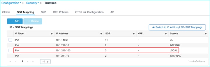
Plus the assignment shows up in the Configuration > Security > TrustSec > SGT Mapping table:
When traffic flows from the wireless client to a north-bound wired endpoint, this Default SGT is propagated successfully. Firstly showing the propagation via inline tagging (CMD) – showing the interesting snippet of a capture received on the adjacent Cat9k:
Ethernet II, Src: 7c:dd:90:ee:99:2c (7c:dd:90:ee:99:2c), Dst: 04:6c:9d:1f:88:71 (04:6c:9d:1f:88:71)
Destination: 04:6c:9d:1f:88:71 (04:6c:9d:1f:88:71)
Address: 04:6c:9d:1f:88:71 (04:6c:9d:1f:88:71)
.... ..0. .... .... .... .... = LG bit: Globally unique address (factory default)
.... ...0 .... .... .... .... = IG bit: Individual address (unicast)
Source: 7c:dd:90:ee:99:2c (7c:dd:90:ee:99:2c)
Address: 7c:dd:90:ee:99:2c (7c:dd:90:ee:99:2c)
.... ..0. .... .... .... .... = LG bit: Globally unique address (factory default)
.... ...0 .... .... .... .... = IG bit: Individual address (unicast)
Type: 802.1Q Virtual LAN (0x8100)
802.1Q Virtual LAN, PRI: 0, DEI: 0, ID: 210
000. .... .... .... = Priority: Best Effort (default) (0)
...0 .... .... .... = DEI: Ineligible
.... 0000 1101 0010 = ID: 210
Type: CiscoMetaData (0x8909)
Cisco MetaData
Version: 1
Length: 1
Options: 0x0001
SGT: 3
Type: IPv4 (0x0800)
Secondly, showing the mapping being received by the adjacent Cat9k over SXP:
Kernow-C9k-top#show cts role-based sgt-map 10.1.210.100
Active IPv4-SGT Bindings Information
IP Address SGT Source
============================================
10.1.210.100 3 SXP
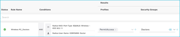
If ISE is then set to assign a dynamic SGT, it takes precedence. Set the SGT assignment within ISE back to SGT Doctors (SGT 34):
Re-auth the wireless client and recheck the assignment within the C9800, the dynamic assignment takes precedence over the Default SGT set in the Policy Profile:
The conclusion is that setting the SGT in the Default SGT field within a Policy Profile is a great way to statically assign an SGT to be used by default if there is no dynamic assignment from ISE. The default assignment would be for all endpoints using that Policy Profile but any dynamic SGT assigned from ISE would take precedence.
C9800 SGT learned through VLAN:SGT static mapping, sent via SXP and enforcing Off-Platform (Not Supported)
A static VLAN:SGT mapping is generally useful to learn of dynamic IP addresses assigned to endpoints on a VLAN and to assign an SGT to them. To learn the IP addresses, IP device tracking would need to be enabled. This use-case tests the functionality on the C9800 where IP addresses of wireless devices using an SSID would be tracked, assigned to a static SGT and propagated off-platform using SXP.
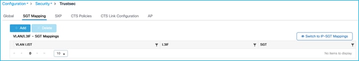
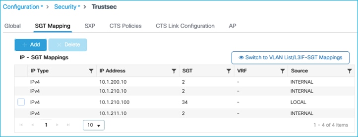
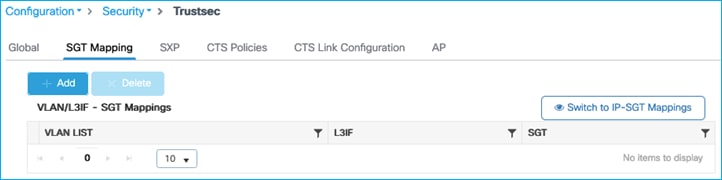
Do not assign SGT to client dynamically from ISE, assign static VLAN:SGT on C9800 instead. Navigate to Configuration > Security > TrustSec > SGT Mapping:
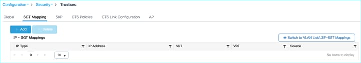
Click on the ‘Switch to VLAN List/L3IF-SGT Mappings’ link near the right-hand side of the screen:
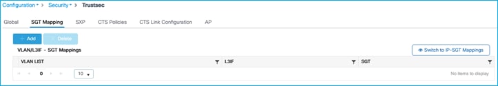
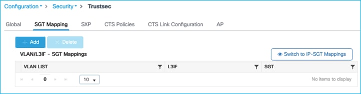
Click ‘Add’ and select VLAN LIST and enter vlan 210 with SGT 34:
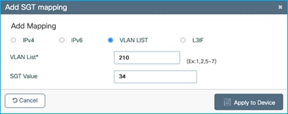
Click Apply:
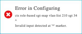
Nothing is entered into the table:
Using CLI on C9800, the command option does not exist:
9800-17.9.1(config)#cts role-based sgt-map ?
A.B.C.D IPv4 host address
A.B.C.D/nn IPv4 prefix <network>/<length>, e.g., 35.0.0.0/8
X:X:X:X::X IPv6 host address x:x::y
X:X:X:X::X/<0-128> IPv6 prefix <network>/<length> (x:x::y/<z>)
host Host IP address
vrf Select VPN Routing/Forwarding instance for the binding
VLAN:SGT static mapping is not supported on the C9800 controller.
The following DDTS was opened for this use-case CSCwd06900 C9800 wireless static VLAN to SGT mapping GUI provisioning generates error.
It has been decided to temporarily hide the option to ‘Switch to VLAN List/L3IF-SGT Mappings’ under Configuration > Security > TrustSec > SGT Mapping in ongoing releases. If either of the two features are required in the future, then the functionality can be investigated and re-introduced. The following DDTS was opened to hide the option:
CSCwd14077 C9800: Hide the option to switch to VLAN List and L3IF to SGT Mappings in SGT Mapping screen
C9800 CTS Provisioning and Device Enrollment
In order for the C9800 to carry out enforcement on-platform, it needs to download a Protected Access Credential (PAC) and the TrustSec Environment-Data from ISE.
Environment-Data includes the following:
Policy server IP - the ISE instance that policy is requested from
Device SGT – the SGT assigned to internal interfaces of the C9800 itself
All SGT names with associated numbers
Within ISE, the ISE instance used for policy download requests is set at Work Centers > TrustSec > Components > TrustSec Servers > TrustSec AAA Servers:
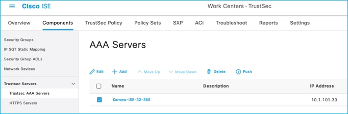
If there is only one ISE instance in your deployment, then this entry needs to be the Hostname and IP of your one ISE instance. If you have a distributed ISE deployment, then this Hostname and IP will be the ISE instance chosen to handle all policy downloads for the network devices. If multiple entries are added in this ISE table, then the network devices will always download policy from the 1st entry in the list unless that ISE instance is unreachable, in which case the 2nd entry in the table will be attempted. So, in normal operations, all network devices will download policy from the 1st entry in the list.
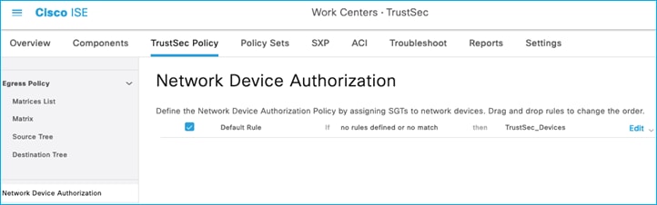
The Device SGT is also downloaded within the Environment-Data. Within ISE, the Device SGT is set at Work Centers > TrustSec > TrustSec Policy > Network Device Authorization:
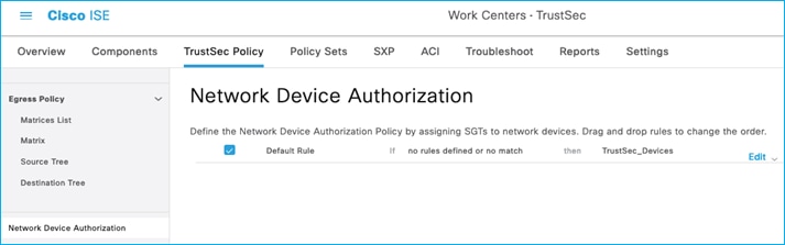
When you first install ISE there is a pre-existing SGT called TrustSec_Devices which is assigned SGT 2. Best practice is to use this pre-existing SGT for assigning to all devices in the network within the GBP ‘domain’. Later releases of ISE pre-configure the Network Device Authorization table to assign TrustSec_Devices SGT 2 to all network devices requesting environment-data but check that SGT TrustSec_Devices is configured and not Unknown (SGT 0).
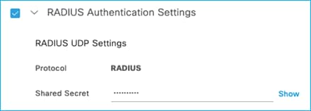
Note down some information from the ISE Network Device entry for the C9800. The network device entries can be found at Administration > Network Resources > Network Devices. The RADIUS password is important, note this down after pressing ‘Show’ to display the characters:
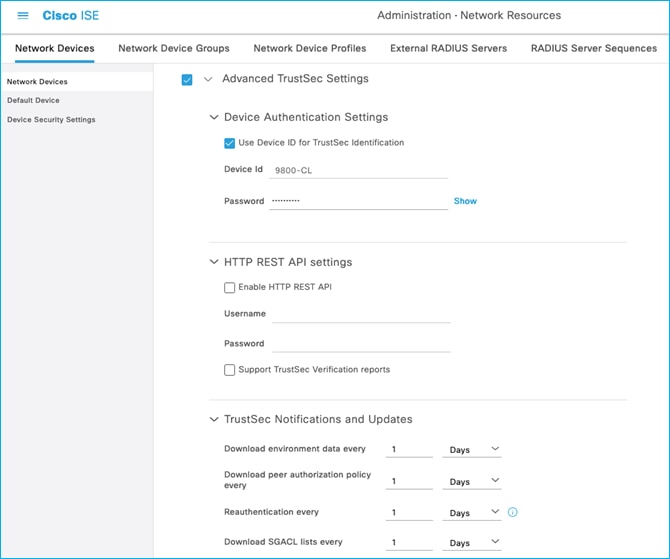
Scroll down to the ‘Advanced TrustSec Settings’ enabled with a Device ID entered with appropriate password, note these down:
Note: The PAC is automatically generated by ISE and downloaded to the network devices when requested.
Then collect the information needed from the C9800 itself to setup CTS communications, navigate to Configuration > Security > AAA > Servers/Groups:
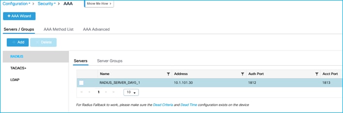
Note the Server name and IP (RADIUS_SERVER_DAY0_1 and 10.1.101.30 in this example), then click on the Server Groups sub-menu:
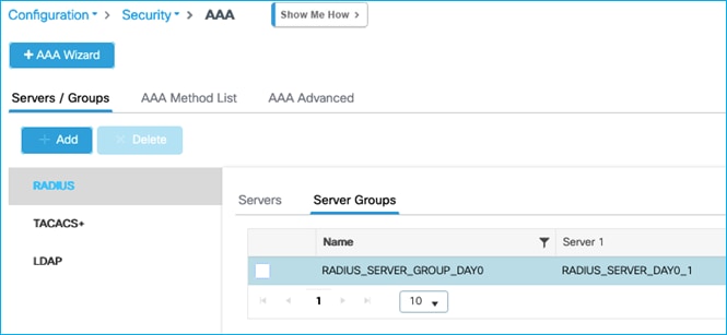
And note the Server Group name (RADIUS_SERVER_GROUP_DAY0 in this example).
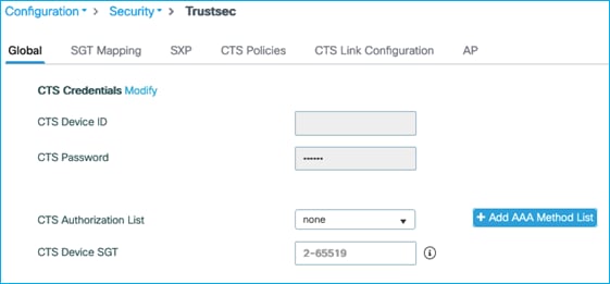
Then, on the C9800, navigate to Configuration > Security > TrustSec > Global.
Firstly, set the CTS Authorization List, click on ‘Add AAA Method List’ as shown in blue here:
Enter the Server name, Server IP and Server Group name we copied above from the C9800, and the PAC key is the RADIUS password/shared secret that was entered into the ISE Network Device screen. The Network Authorization Method List Name can be a new name for example CTS-Authz-List:
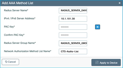
Click ‘Apply to Device’.
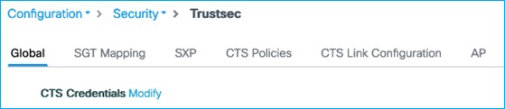
Then, back on the Global tab, click the ‘Modify’ link to update the CTS Credentials settings:
Update the settings to coincide with the Device ID and associated password entered in ISE in the Advanced TrustSec Settings of the Network Device entry:
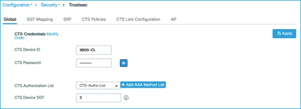
Click Apply.
An example of changes implemented in the C9800 are marked in blue below:
aaa group server radius RADIUS_SERVER_GROUP_DAY0
server name RADIUS_SERVER_DAY0_1
!
aaa authentication login authentication_login_day0 group RADIUS_SERVER_GROUP_DAY0
aaa authentication dot1x authentication_dot1x_day0 group RADIUS_SERVER_GROUP_DAY0
aaa authorization network CTS-Authz-List group RADIUS_SERVER_GROUP_DAY0
aaa accounting identity Kernow-Acc-List start-stop group RADIUS_SERVER_GROUP_DAY0
!
cts authorization list CTS-Authz-List
cts sgt 2
!
aaa server radius dynamic-author
client 10.1.101.30 server-key XXXX
!
radius server RADIUS_SERVER_DAY0_1
address ipv4 10.1.101.30 auth-port 1812 acct-port 1813
pac key xxxx
9800-17.9.1#show cts credentials
CTS password is defined in keystore, device-id = 9800-CL
Note: The procedure above modifies the existing RADIUS server config to include the PAC keyword. If two separate radius server configurations are desired (one without PAC for AAA and one with PAC for CTS operations) then that is also possible.
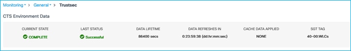
Once applied, navigate to Monitoring > General > TrustSec. A CTS PAC and the CTS Environment-Data should have been downloaded from ISE (with the Device SGT, Server List and Security Group Table):
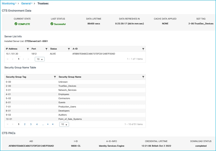
If these have not been downloaded, then re-check the configuration and use the ISE Live Logs to determine if any errors are being displayed for the requests.
ISE initiating updates (via CoA or SSH) to C9800 for Environment-Data
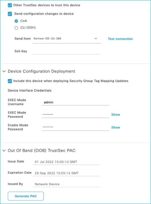
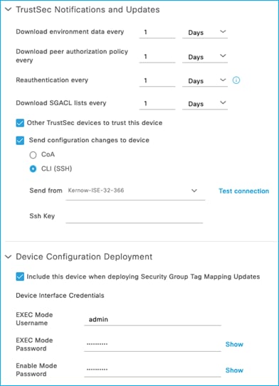
For all the scenarios in this section, the protocol used for ISE to make change requests is configured in the ISE Network Device screen. In ISE, navigate to Administration > Network Resources > Network Devices, click on the C9800 entry. Scroll down to the Advanced TrustSec Settings section and then the TrustSec Notifications and Updates:
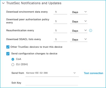
See the setting to select ‘Send configuration changes to device’ using CoA or CLI (SSH). If CLI (SSH) is selected then the credentials ISE uses to log into the C9800 can be entered just below that in the screen, as shown here:

Generally, it is best practice to leave the setting as default i.e. use CoA for changes. It is common though for the ‘Send from’ option to be set as the ISE Policy Service Node (PSN) nearest the C9800.
In networks with a very large number of network devices and when several policy changes are made at the same time, it may be beneficial to change from using CoA to use SSH. The reason is that there is a CoA message sent from ISE per policy change for every network device, generating many messages. Using SSH sends just one message per network device informing the network device to refresh policy.
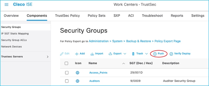
Adding SGT and pushing the change via CoA
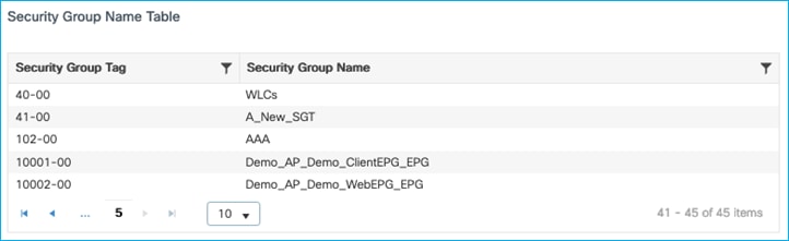
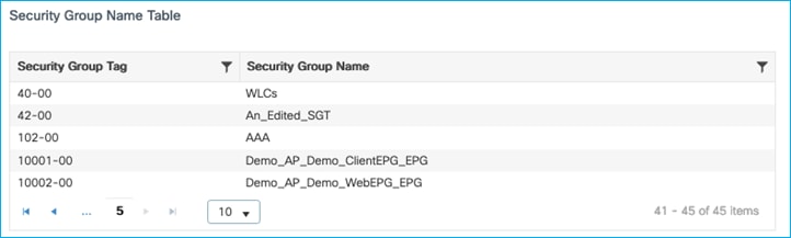
With the ISE Network Device set to use CoA for instigating changes, add a new SGT in ISE (an example: A_New_SGT with SGT 40) and push the change (this Push option is at the top of the Security Group table, and this instigates the RADIUS CoA to implement the change on the C9800); see here:
On the C9800, navigate to Monitoring > General > TrustSec, and go through the Security Group Name Table to find the newly added SGT:
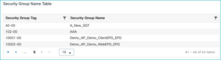
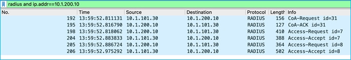
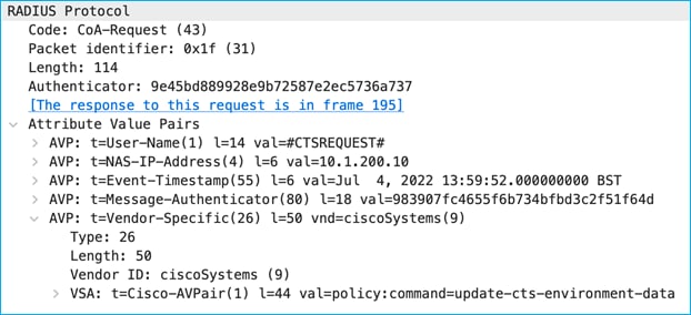
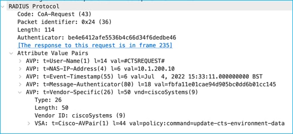
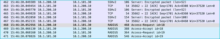
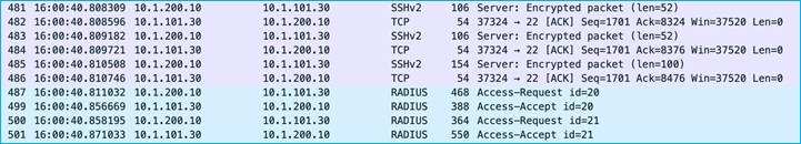
A debug on ISE shows the CoA Request being sent to the C9800 to inform of a CTS Environment-Data update, plus the subsequent messages:
CoA Request:
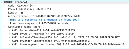
CoA Ack:
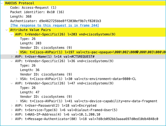
The above CoA Request instigates the C9800 to send a RADIUS Request to download any change:
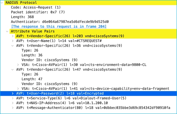
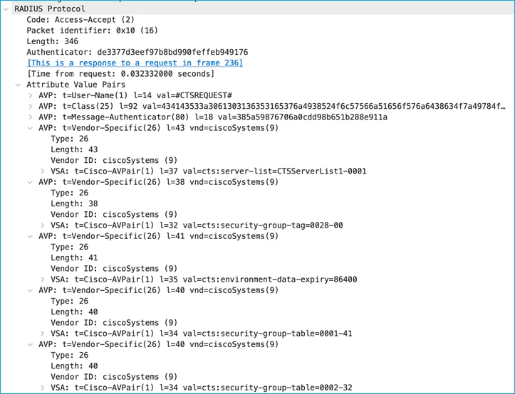
Reply from ISE indicates there are two SGT tables, 0001 and 0002 along with associated version numbers. The SGT list is chopped up into manageable chunks to reduce the amount of data needing to be downloaded (hence this example shows 2 chunks, table 0001 and table 0002):
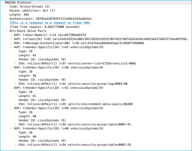
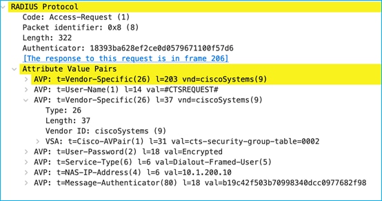
The security-group-table 0001 shows a version of 41 (cts:security-group-table=0001-41) and this matches what the C9800 already internally has. So, no request is made to update any SGTs within table 0001. The version number for table 0002 (29) has been incremented since the C9800 last downloaded the list, so a request is made to download the new table 0002 list:
ISE replies with that new list including the new SGT that was recently added:
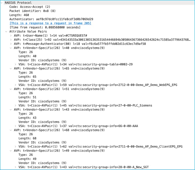
The SGT was successfully added to the C9800 using CoA.
Editing SGT and pushing the change via CoA
After adding SGT 40 above with the name A_New_SGT, both the name and number can be modified in ISE with a CoA being used to update the C9800. Edit the SGT in ISE at Work Centers > TrustSec > Components > Security Groups and change the name to An_Edited_SGT with a new number (example 41). Push the change from ISE.
Check in the C9800 at Monitoring > General > TrustSec, and go through the Security Group Name Table to find the newly edited SGT:
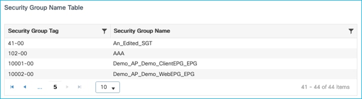
Both the SGT name and number were successfully updated on the C9800 using CoA.
Deleting SGT and pushing change via CoA
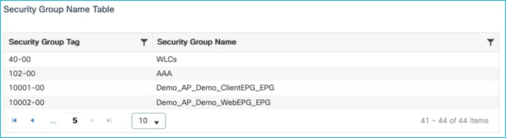
Delete that last SGT with name An_Edited_SGT in ISE at Work Centers > TrustSec > Components > Security Groups. Push the change to network devices.
Check in the C9800 at Monitoring > General > TrustSec, and go through the Security Group Name Table to see that An_Edited_SGT has been deleted:
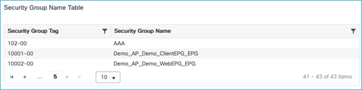
The SGT was successfully deleted on the C9800 using CoA.
Editing Device-SGT and pushing change via CoA
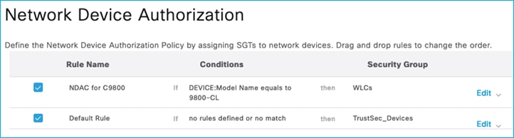
In ISE, add a specific rule at Work Centers > TrustSec > TrustSec Policy > Network Device Authorization:
Click the down arrow next to Edit and insert a new rule:
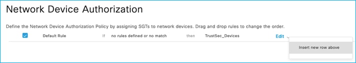
Provide a new rule name and click on the Condition(s) field.
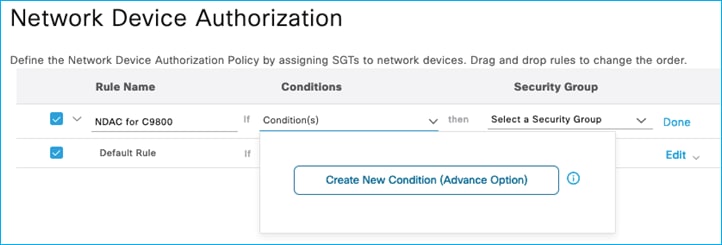
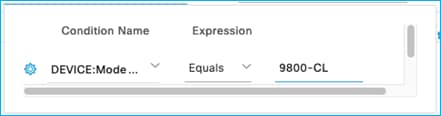
Create a new condition – for example, if the C9800 Network Device entry in ISE has the Model Name entered as ‘9800-CL’, then use that as a condition in this new rule. Click ‘Select Attribute’ and choose Model Name, then under Expression use equals with 9800-CL in the matching criteria:
Click Done, then select Edit to add an SGT to be assigned when this condition is matched. E.g. one has been added in this system called WLCs (SGT 40):
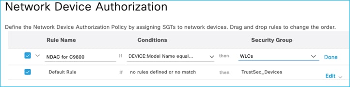
Click Done then Save. To the right of the Save option, click ‘Push’ to instigate a CoA message to inform the C9800 that a change to the Device SGT has occurred.
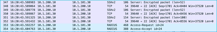
A wireshark capture shows the interaction:
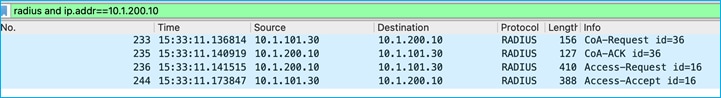
ISE sends a RADIUS CoA to inform of the Environment-Data change:
The C9800 acknowledges the CoA.
The C9800 then requests the updated Environment-Data table:
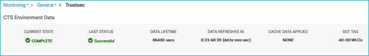
Finally, ISE sends the updated table with the new Device SGT cts:security-group-tag=0028 (which is hex, decimal = 4):
In the C9800 UI, navigate to Monitoring > General > TrustSec, and check the Device SGT near the top-right (it is labelled SGT TAG in the UI); it should have been updated (a screen refresh may be needed):
If you scroll to the bottom of that screen, you’ll see the internal IP addresses of the C9800 have now been mapped to the new SGT:
The conclusion is that CoA can successfully be used to update the Device SGT within the C9800.
To continue testing, the Device SGT was set back to TrustSec_Devices SGT 2.
Adding SGT and pushing the change via SSH
Now, change the C9800 Network Device entry in ISE to use SSH for updates instead of using RADIUS CoA.
In ISE add a new SGT, perhaps called ‘A_New_SGT’ with SGT 41. Push the change so that the C9800 is made aware of the addition.
On the C9800, navigate to Monitoring > General > TrustSec, and go through the Security Group Name Table to find the newly added SGT:
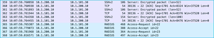
A wireshark capture shows SSH being used to inform the C9800 of a change, then the C9800 uses RADIUS to check of any change made:
SSH can be used successfully from ISE to add a new SGT in the C9800.
Editing SGT and pushing the change via SSH
Using ISE with SSH option selected, edit the SGT just added (A_New-SGT, SGT 41), to be ‘An_Edited_SGT’ with SGT 42. Push the change to instigate an SSH request from ISE to the C9800 to inform of an environment-data change.
The C9800 shows the change under Monitoring > General > TrustSec:
Wireshark capture shows SSH being used to inform the C9800 of the change and then the C9800 requesting that change using RADIUS:
To conclude, SGTs can be edited on the C9800 using ISE and SSH to inform of the change.
Deleting SGT and pushing the change via SSH
Use ISE with SSH option selected to delete the SGT called An_Edited_SGT, SGT 41. Push the change.
The C9800 shows the change under Monitoring > General > TrustSec:
Wireshark shows SSH being used to inform the C9800 of the change. The C9800 then requests the change.
SGTs can be deleted from the C9800 using ISE and the SSH protocol to inform of the deletion.
Editing Device’s SGT and pushing the change via SSH
As when showing this option using RADIUS CoA, add an additional rule in ISE under Work Centers > TrustSec > TrustSec Policy > Network Device Authorization to be used by the c9800 when downloading the Device SGT:
Use the ‘Push’ function to instigate an SSH message to inform the C9800 that a change to the Device SGT has occurred.
In the C9800 UI, navigate to Monitoring > General > TrustSec, and check the Device SGT near the top-right (it is labelled SGT TAG in the UI); it should have been updated (a screen refresh may be needed):
If you scroll to the bottom of that screen, you’ll see the internal IP addresses of the C9800 have now been mapped to the new SGT.
A wireshark capture shows that SSH is used to inform the C9800 of the change before the C9800 uses RADIUS to download the change:
SSH can be used by ISE to update the C9800 Device SGT.
To continue testing, the Device SGT was set back to TrustSec_Devices SGT 2.
East-West enforcement refers to policy enforcement on traffic from wireless client to another wireless client. There are multiple use cases for this scenario:
Clients connected to the same SSID and same policy profile, upon successful authentication, they are assigned to two SGTs. For example, doctors and nurses would use the same Employee SSID but they receive different SGTs so that a specific policy can be assigned. This is the use case below referred to as “E-W using single policy profile”.
Another use case is where clients connected to two separated SSIDs and policy profiles, for example Doctors and Guest, would receive different SGTs and a specific policy is applied. This is the use case below referred to as “E-W using different policy profile”.
E-W using single Policy Profile
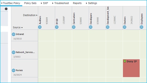
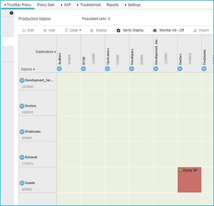
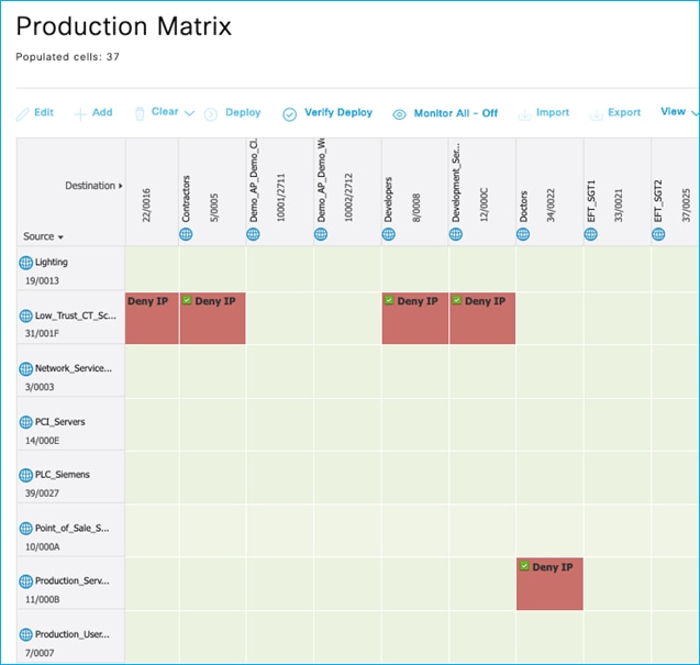
In this case, there is one SSID/WLAN (Employee) and one associated Policy Profile; two groups of users are defined on ISE: Doctors and Nurses. As you can see from ISE policy matrix below, Doctors are assigned SGT = 34 and Nurses = 36 and the SGACL has been configured to deny traffic from Nurses to Doctors.
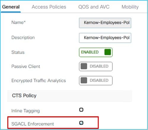
When a nurse and a doctor wireless clients connect to the Employee SSID, they are assigned to the respective SGT, the policy is downloaded on C9800 automatically. For the policy to be enforced on wireless clients, you need to enable SGACL enforcement on the policy Profile:
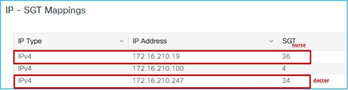
You can verify under Monitoring > General > TrustSec page on the C9800. Here is the IP to SGT mapping:
Doctor got an IP of 172.16.210.247 and SGT = 34; the nurse 172.16.210.19 and SGT = 36. Both are on the same subnet and same policy profile. The GBP policy is downloaded to deny traffic from SGT 36 to SGT 34:
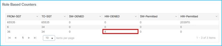
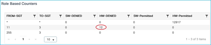
 If a ping is started between the two clients, you can see the HW-DENIED counter increasing:
In the past, CTS policies have been seen to remain even after removing enforcement. This is fixed and supported from 17.9.1: CSCwb52864 HCA: 9800L-HA policies were intact even after removing the enforcement from the wireless profile.
E-W Using different Policy Profiles
In this use case, you have two SSIDs (Employee and Guest) and two different policy profiles to associate the clients to two different VLANs, 210 and 211 respectively. A group-based policy is configured on ISE to assign Guest to SGT = 6 and to deny traffic from Guests (source) to Doctors (destination), as you can see from the policy matrix below:
When a guest and a doctor wireless clients connect to the respective SSID, they are assigned the SGT and the policy is downloaded on C9800 automatically. For the downloaded policy to be enforced on the wireless clients you need to have SGACL enforcement enabled on the policy profile. Since you have two policy profiles, the rule is no different than on other IOS-XE network devices: enforcement happens closest to the destination; in this case this means that the SGACL enforcement needs to be enabled only on the destination policy profile, which is the Employees one that the Doctor belongs to for enforcement from Guest to Doctor:
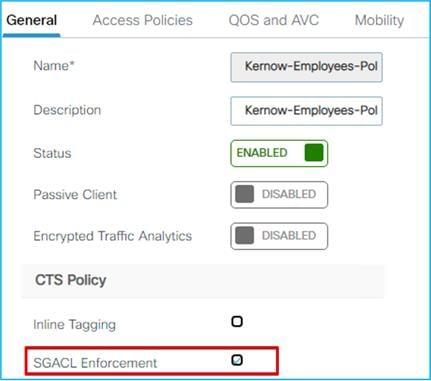
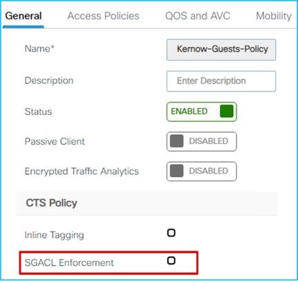
As you can see below, there is no enforcement set on the Guest policy profile:
You can verify this under Monitoring > General > TrustSec page on the C9800. Here is the IP to SGT mapping:
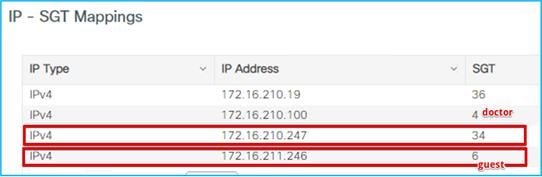
Doctor got an IP of 172.16.210.247 and SGT = 34; the guest belongs to a different subnet (vlan 211) and is assigned IP 172.16.211.246 and SGT = 6. The GBP policy is downloaded to deny traffic from SGT 6 to SGT 34. If a ping is started between the two clients, you can see the HW-Denied counter is increasing:
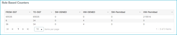
This confirms that the enforcement happened and was enforced on the destination policy profile.
North to South (N-S) Enforcement on C9800
Here the use-case is to enforce a policy on traffic coming from the wired network to the wireless network (commonly known as north to south traffic).
N-S Enforcement Using SXP for Source
Ensure the Policy Profile in use has SGACL Enforcement enabled:
Also ensure that the upstream switch is not set for inline tagging (so inline CMD is not received):
interface GigabitEthernet1/0/15
switchport trunk allowed vlan 200,210,211
switchport mode trunk
switchport nonegotiate
ip dhcp snooping trust
end
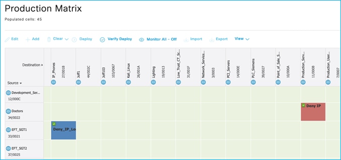
Wired Production_Server SGT 11, 10.1.140.2 (source) sending data towards wireless client Doctors SGT 34, 10.1.210.100 (destination). Policy exists in ISE to deny traffic from Production_Servers to Doctors:
![]()
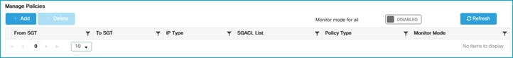
Without wireless client connected, no policies downloaded to C9800 yet, check at Configuration > Security > TrustSec > CTS Policies:
When wireless client connects, ISE assigns Doctors SGT via authorization table:
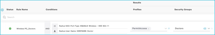
C9800 shows the assigned SGT at bottom of Monitoring > Wireless > Clients > Click Client > General > Security Information (remember this number is in hexadecimal):
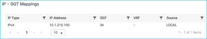
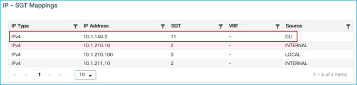
Mapping (10.1.210.100:SGT 34) shown at Configuration > Security > TrustSec > SGT Mapping:
The C9800 understands the destination SGT (Doctors SGT 34) and has a policy downloaded to prevent traffic from Production_Servers SGT 11 from communicating with that group. However, the C9800 also needs to understand what IP addresses are in the source group i.e. in the Production_Servers SGT 11 group.
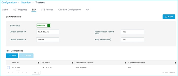
The C9800 will learn this using SXP in this use-case. Ensure SXP is up and operational and the C9800 is listening to mappings from the peer (Cat9k in this example):
Configuration > Security > TrustSec > SXP:
Note: There is no support of IPv6 based peer SXP connections (but the IPv4 based connections do support the propagation of IPv6 SGT bindings).
Kernow-Cat9300-b#show cts sxp connections brief
SXP : Enabled
Highest Version Supported: 5
Default Password : Set
Default Key-Chain: Not Set
Default Key-Chain Name: Not Applicable
Default Source IP: 10.1.200.1
Connection retry open period: 120 secs
Reconcile period: 120 secs
Retry open timer is not running
Peer-Sequence traverse limit for export: Not Set
Peer-Sequence traverse limit for import: Not Set
----------------------------------------------------------------------------------------
Peer_IP Source_IP Conn Status Duration
----------------------------------------------------------------------------------------
10.1.200.10 10.1.200.1 On 0:15:51:13 (dd:hr:mm:sec)
Total num of SXP Connections = 1
Now, add a static mapping in the Cat9k for the Production_Server SGT 11 so it can send the mapping via SXP to the C9800:
Kernow-Cat9300-b(config)#cts role-based sgt-map 10.1.140.2 sgt 11
C9800 shows the mapping learned via SXP (Configuration > Security > TrustSec > SGT Mapping):
Note: The C9800 controller does support IPv6 SXP mappings/bindings as well as IPv4.
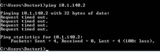
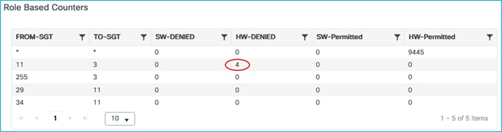
The wireless client is blocked from accessing the Production_Server due to the policy in place:
Enforcement counts shown at Monitoring > General > TrustSec, proving the C9800 enforces wired to wireless using SXP to learn of source SGT:
Note: the C9800 controller supports SGACL enforcement for both IPv4 and IPv6 client traffic.
SXP Filters for N-S Enforcement
You can apply a filter for SXP connections on the C9800 that receive mappings from elsewhere. An example is the C9800 being a listener for mappings from a Cat9k. The SXP filters are supported only using the CLI, not the GUI/webui today.
C9800 SXP connection set as an SXP listener for the Cat9k peer (10.1.200.1):

Cat9k SXP connection set as a Speaker:
Kernow-Cat9300-b(config)#cts sxp connection peer 10.1.200.10 source 10.1.200.1 password default mode local speaker
Mappings currently being shown on the C9800 (including the mappings learned via SXP from the Cat9k):
9800-17.9.1#show cts role-based sgt-map all
Active IPv4-SGT Bindings Information
IP Address SGT Source
============================================
1.1.1.8 2 SXP
10.1.140.2 11 CLI
10.1.200.1 2 SXP
10.1.210.1 2 SXP
10.1.210.10 2 INTERNAL
10.1.210.100 34 LOCAL
10.1.211.1 2 SXP
10.1.211.10 2 INTERNAL
10.1.249.10 2 INTERNAL
10.3.23.2 2 SXP
10.4.25.2 2 SXP
10.6.50.100 28 SXP
10.6.50.254 2 SXP
A filter will be added on the C9800 to block receiving SGT 2 from the Cat9k:
cts sxp filter-enable
!
cts sxp filter-list block-sgt2
deny sgt 2
permit sgt all <- default rule, otherwise will default deny
!
cts sxp filter-group listener listner-from-Cat9k
filter block-sgt2
peer ipv4 10.1.200.1
On Cat9k configure ‘no cts sxp enable’ and then ‘cts sxp enable’ to refresh the mappings being sent.
Display the results of the filter:
9800-17.9.1#show cts sxp filter-group detailed
Global Listener Filter: Not configured
Global Speaker Filter: Not configured
Listener Groups:
Filter-group: listner-from-Cat9k
Filter-name: block-sgt2
Filter-rules:
10 deny sgt 2 (7)
20 permit sgt all (1)
Total Matches: 8
Default Deny Count: 0
peer 10.1.200.1
New mapping table on the C9800 after filtering has taken place (only 1 entry is now received via SXP from the Cat9k after blocking the entries with SGT 2):
9800-17.9.1#show cts role-based sgt-map all
Active IPv4-SGT Bindings Information
IP Address SGT Source
============================================
10.1.140.2 11 CLI
10.1.210.10 2 INTERNAL
10.1.210.100 34 LOCAL
10.1.211.10 2 INTERNAL
10.1.249.10 2 INTERNAL
10.6.50.100 28 SXP
So, SXP filtering works successfully for mappings received from other devices.
N-S Enforcement Using Inline (CMD) for Source
This use-case is to enforce wired to wireless on the C9800 but use a source SGT learned from the CMD field i.e., learned from inline tagging. The destination SGT will be the SGT assigned to a wireless client.
Ensure there are no SXP or static mappings in the C9800 for Production_Servers SGT 11 – we want the source to be learned from inline tagging (CMD).
C9800 uplink interface towards Cat9k is enabled for inline tagging:
Cat9k peer is set for inline tagging:
interface GigabitEthernet1/0/15
switchport trunk allowed vlan 200,210,211
switchport mode trunk
switchport nonegotiate
cts manual
policy static sgt 2 trusted
ip dhcp snooping trust
end
Authenticate a wireless client as was done in the SXP use-case above, assign SGT 34 from ISE which indicates to the C9800 to download any policy destined for that SGT. Use Configuration > Security > TrustSec > CTS Policies to check the policies downloaded:

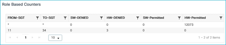
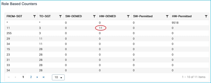
Now, when the Production Server traffic is classified into group Production_Server SGT 11, the C9800 receives this information in every packet from the server within the receiving frame and acts upon it as the source for policy enforcement (Monitoring > General > TrustSec):
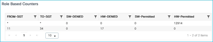
Now, this is with the destination Policy Profile set with SGACL Enforcement. We will now disable SGACL Enforcement on this Policy Profile to see what happens:
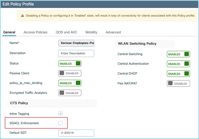
Data is now permitted, so the destination Policy Profile has to have SGACL Enforcement enabled for traffic to be enforced.
No hits are registered for the specific policy under Monitoring > General > TrustSec with SGACL Enforcement disabled on the Policy Profile:
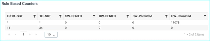
Re-enable on the Policy Profile and data is enforced with hits again being shown:
For another test, we’ll see what happens when inline tagging is disabled on the Policy Profile:
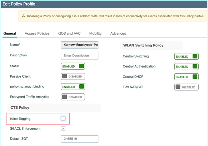
It makes no difference, the source lookup for the CMD in the Layer2 frame still occurs and the traffic is still enforced:
 If inline tagging is enabled on the uplink interface under Configuration > Security > TrustSec > CTS Link Configuration, then it doesn’t matter what is set for Inline Tagging on the Policy Profile. The use of the inline tagging setting on the policy profile will be introduced in a future release.
N-S Enforcement Using IP:SGT Static Mapping for Source
Test is to ensure a static mapping can be added in the C9800 and used as an SGT source lookup for traffic flowing in the wired to wireless direction.
Ensure there are no mappings learned via SXP and inline tagging is disabled on the uplink interface.
Wireless client is connected with dynamic SGT assigned from ISE (SGT 34):
Policy protecting SGT 34 is downloaded (Configuration > Security > TrustSec > CTS Policies):
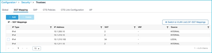
Now, add an IP:SGT static mapping in the C9800 for the Production Server:
Traffic is denied from Production Server to wireless client:
The conclusion is that the C9800 will use static IP:SGT mappings when carrying out a source lookup for enforcing southbound towards wireless clients.
N-S Enforcement Using Subnet:SGT Static Mapping for Source
This use-case is adding a static Subnet:SGT mapping on the C9800 and ensuring it can be used in an SGT source lookup in the wired to wireless direction.
Ensure there are no mappings learned via SXP and inline tagging is disabled on the uplink.
Wireless client is connected with dynamic SGT 34 assigned from ISE:
Policy protecting SGT 34 is downloaded (Configuration > Security > TrustSec > CTS Policies):
Now, add a Subnet:SGT static mapping in the C9800 for the Production Server:
Production Server with SGT 11 is denied communication with wireless client SGT 34 (ICMP reply is blocked):
To conclude, static Subnet:SGT mappings can be used on the C9800 for source lookup when enforcing southbound from wired towards a wireless client.
N-S Enforcement with Wireless Client Using Default SGT Assigned via Policy Profile
It has previously been seen that the Default SGT setting within the Policy Profile can be used as a default classification for wireless clients if there is no dynamic assignment from ISE. This use-case is to ensure that default SGT can be used to enforce traffic from wired to wireless using that default SGT assigned as a destination.
As previously, set Default SGT in the Policy Profile to be 3 as an example:

The wireless client (10.1.210.100) is assigned default SGT 3 if no dynamic SGT assignment is provided from ISE;
seen under Monitoring > General > TrustSec:
If there are policies available in ISE destined for SGT 3, then they are dynamically downloaded by the C9800. In this example, ISE has 2 policies that are downloaded, as shown here in the C9800 permissions:
9800-17.9.1#show cts role-based permissions
IPv4 Role-based permissions default:
Permit IP-00
IPv4 Role-based permissions from group 11:Production_Servers to group 3:Network_Services:
Deny IP-00
IPv4 Role-based permissions from group 255:Quarantined_Systems to group 3:Network_Services:
Deny IP-00
IPv4 Role-based permissions from group 29:Access_Points to group 11:Production_Servers:
AllowWeb-00
IPv4 Role-based permissions from group 34:Doctors to group 11:Production_Servers:
Permit IP-00
RBACL Monitor All for Dynamic Policies : FALSE
RBACL Monitor All for Configured Policies : FALSE
As can be seen from the Monitoring > General > TrustSec table, a static CLI mapping also exists for a server north-bound of the controller:
If traffic is sent from that north-bound server (10.1.140.2 / SGT 11) to the wireless client (10.1.210.100/ SGT 3) then the traffic is enforced successfully as seen at Monitoring > General > TrustSec:
9800-17.9.1#show cts role-based sgt-map 10.1.140.2
Active IPv4-SGT Bindings Information
IP Address SGT Source
============================================
10.1.140.2 11 SXP
Enforcement is successful when traffic is attempted to be sent from that server (10.1.140.2 / SGT 11) to the wireless client (10.1.210.100 / SGT 3):
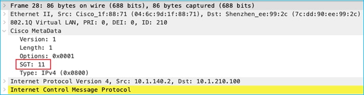
Lastly, If the source mapping is learned via inline tagging/CMD, then enforcement is also successful. In this example, the server 10.1.140.2 has a mapping to SGT 11 added in a network device north-bound of the C9800 and inline tagging carries it to the C9800 via the CMD field in the L2 frame. Using the C9800 GUI Troubleshooting > Packet Capture function, see the source SGT captured coming from the wired endpoint:
Enforcement hits are shown up under Monitoring > General > TrustSec:
The conclusion is that the Default SGT set on the C9800 Policy Profile can be used as a destination for enforcement (wired to wireless). It doesn’t matter where the source SGT is learned from, the above tests show the source SGT learned from CLI, SXP and inline tagging/CMD.
N-S Enforcement Using Static VLAN:SGT for Source (Not Supported)
Under Configuration > Security > TrustSec > SGT Mapping, click the option to ‘Switch to VLAN List/L3IF-SGT Mappings’:
Then click ‘Add’:
Select the option for adding a VLAN LIST and then enter the VLAN to learn IP addresses from and the SGT to assign:

Apply:
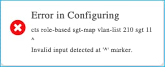
Table remains empty:
Static VLAN:SGT mapping is not supported on the C9800 and the following DDTS was opened for the generated error: CSCwd06900 C9800 wireless static VLAN to SGT mapping GUI provisioning generates error.
It has been decided to temporarily hide the option to ‘Switch to VLAN List/L3IF-SGT Mappings’ under Configuration > Security > TrustSec > SGT Mapping in ongoing releases. If either of the two features are required in the future, then the functionality can be investigated and re-introduced. The following DDTS was opened to hide the option: CSCwd14077 C9800: Hide the option to switch to VLAN List and L3IF to SGT Mappings in SGT Mapping screen.
N-S Enforcement Using Static L3IF:SGT for Source
Generally, the L3IF:SGT classification function is for a network device to learn of routing prefixes and to assign an SGT to them. It is typically used for a company to connect to a partner organisation, learning of routing prefixes and assigning an SGT to delineate them from their own prefixes.
Add a L3 interface to the C9800:
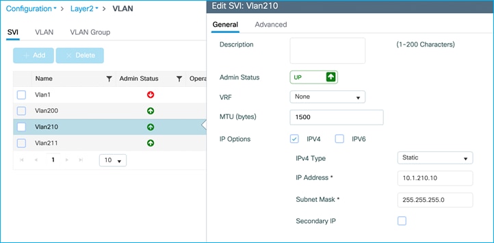
Ensure there are no other static mappings present, no SXP and inline tagging is disabled on the uplink.
Under Configuration > Security > TrustSec > SGT Mapping, click the option to ‘Switch to VLAN List/L3IF-SGT Mappings’:
Then click ‘Add’:
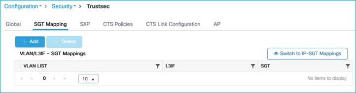
Select the option to add a L3IF mapping, then add a L3 interface and an SGT value to assign:
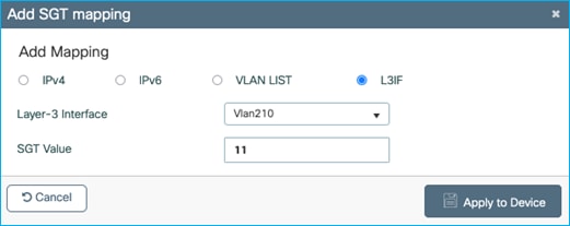
An entry is added to the table:
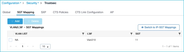
The CLI added via the GUI action:
interface Vlan210
cts role-based sgt-map sgt 11
The mapping table shows:
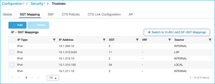
Traffic is enforced from the 10.1.210.0/24 subnet to the wireless client:
Kernow-Cat9300-b#ping 10.1.210.100 source 10.1.210.1
Type escape sequence to abort.
Sending 5, 100-byte ICMP Echos to 10.1.210.100, timeout is 2 seconds:
Packet sent with a source address of 10.1.210.1
.....
Success rate is 0 percent (0/5)
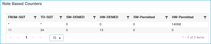
So, the L3IF mapping does add a relevant Subnet mapping but that isn’t really the intention of the L3IF function. If a Subnet:SGT mapping is required then why not just use the static Subnet:SGT function?
As the C9800 is largely a L2 platform the full function cannot currently be realised.
It has been decided to temporarily hide the option to ‘Switch to VLAN List/L3IF-SGT Mappings’ under Configuration > Security > TrustSec > SGT Mapping in ongoing releases. If either of the two features are required in the future, then the functionality can be investigated and re-introduced. The following DDTS was opened to hide the option: CSCwd14077 C9800: Hide the option to switch to VLAN List and L3IF to SGT Mappings in SGT Mapping screen.
N-S Precedence Order for Classification and Enforcement
There is a strict order of precedence for source SGT lookup and enforcement, as defined by the Group-Based Policy specification. SGT received by inline tagging is the highest priority, then SXP with CLI last in the supported classification methods. Additionally, it works on longest match (an example being prioritising IP /32 mappings over /24.
This use-case configures mappings as per the following:
| IP Address |
Assigned SGT |
Learned From |
| 10.1.140.2 |
11 (Production_Servers) |
Inline Tagging (CMD) |
| 10.1.140.2 |
12 (Development_Servers) |
SXP |
| 10.1.140.2 |
13 (Test_Servers) |
CLI (IP:SGT) |
| 10.1.140.0/24 |
14 (PCI_Servers) |
CLI (Subnet:SGT) |
Testing will occur with all four classifications present; SGT 11 should take precedence (learned from inline tagging (CMD).
Without inline tagging, SXP should take precedence with SGT 12. Without inline and SXP, CLI IP:SGT should take precedence with SGT 13 and lastly CLI Subnet:SGT with SGT 14.
Firstly, enable inline tagging on the C9800 uplink and Cat9k peer:
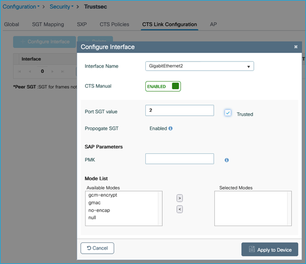
interface GigabitEthernet1/0/15
switchport trunk allowed vlan 200,210,211
switchport mode trunk
switchport nonegotiate
cts manual
policy static sgt 2 trusted
ip dhcp snooping trust
end
On the Cat9k, add a classification for the Production Server so the C9800 receives this SGT inline:
Kernow-Cat9300-b(config)#cts role-based sgt-map 10.1.140.2 sgt 11
Now, add two static mappings in the C9800, one IP:SGT and one Subnet:SGT:
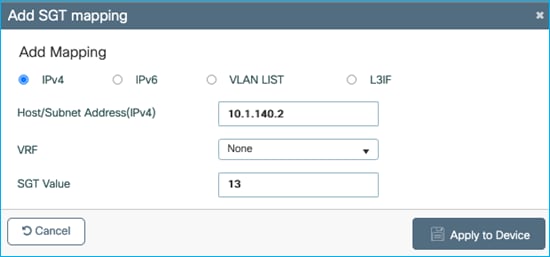
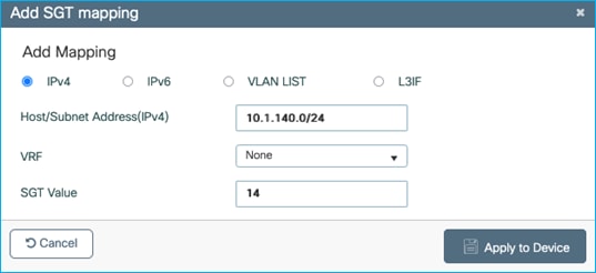
Both the /32 and /24 entries are shown in the SGT Mapping table:
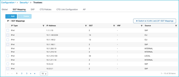
Now, add an SXP connection from another platform (Cat6k in this example) to the C9800 in order to add an SXP mapping. Cat6k will be an SXP Speaker whilst the C9800 will be the SXP Listener.
On C9800, use Configuration > Security > TrustSec > SXP to add a new SXP connection:
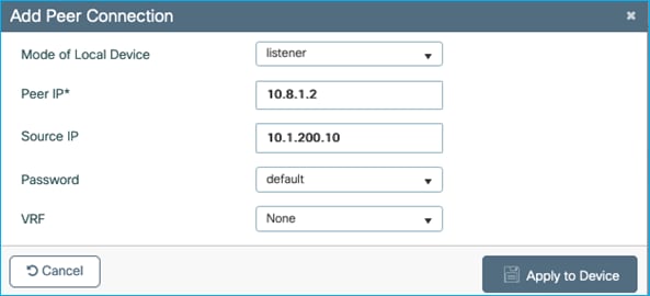
(where 10.8.1.2 is the peer IP address on the Cat6k).
Once the connection is added on the Cat6k end, the C9800 shows the connection as ‘On’:
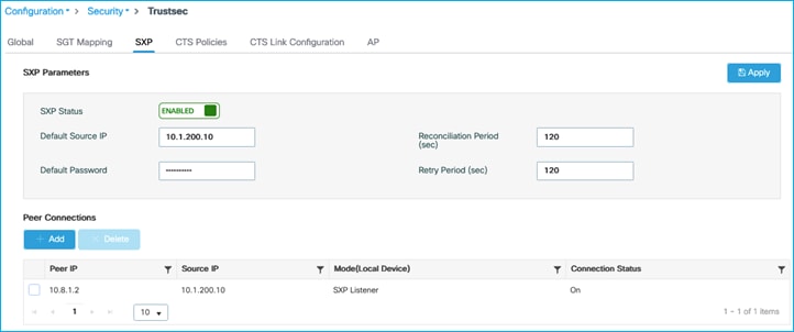
Now, add the Production Server mapping in the Cat6k so that the C9800 can learn it via SXP:
Kernow-6500(config)#cts role-based sgt-map 10.1.140.2 sgt 12
C9800 learns it via SXP but you’ll see that the C9800 has prioritised the mapping from SXP over the same IP:SGT mapping added via CLI (the CLI entry has been removed from the table):
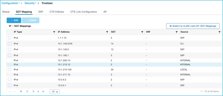
So, the C9800 prioritises SXP mappings over statically added IP:SGT /32 entries.
With the C9800 already showing classification prioritisation behaviour of SXP over CLI, we are left with:
Inline tagging, assigning SGT 11 to 10.1.140.2
SXP assigning SGT 12 to 10.1.140.2
Subnet:SGT assigning SGT 14 to 10.1.140.2
Add policies in ISE to prove the prioritisation:
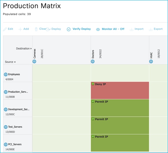
The C9800 downloads the policies:
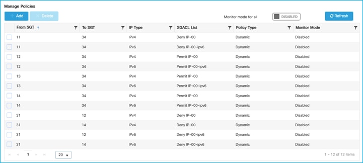
Traffic is denied between the wireless client (SGT 34) and the Production Server IP 10.1.140.2, and the Counters table shows it’s the policy from 11 to 34 that is being hit:
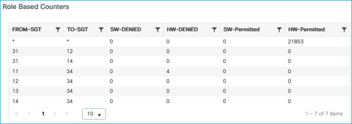
So, inline tagging does take precedence.
Note: Inline tagging will always take precedence, even if the received SGT is 0/Unknown.
Now, remove inline tagging and set a deny policy on the SXP mapping with SGT 12. Traffic is enforced so SXP does come next in precedence order:
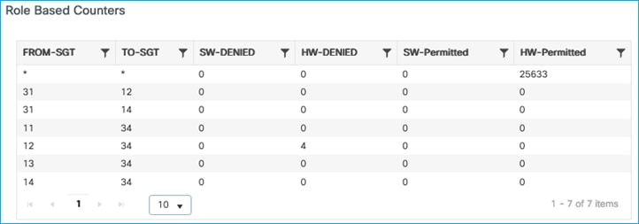
Remove the SXP mapping and SGT 13 is acted upon which is the static IP:SGT mapping using /32:
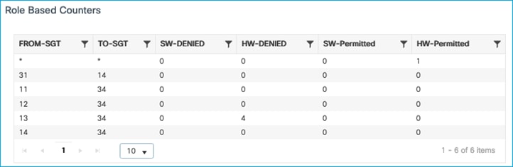
Remove the /32 IP:SGT mapping and SGT 14 is acted upon which is the /24 IP:SGT mapping:
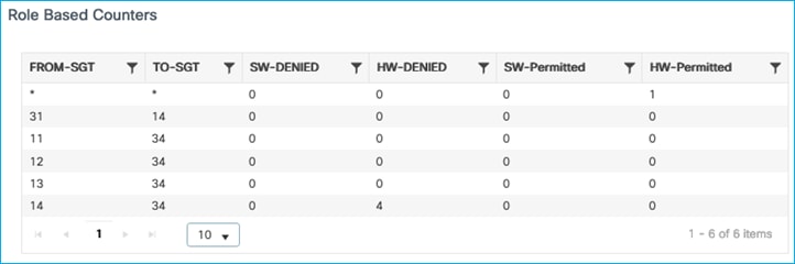
Note: In order to clear the role-based counters, navigate to Administration > Command Line Interface, and under the Exec option, run the command “clear cts role-based counters”.
The conclusion is that the order of precedence for classification and enforcement is comparable with the operation of other Cisco network devices.
CoA and SSH for Policy Updates
This use-case is testing CoA and SSH pushed from ISE for policy updates.
In ISE, navigate to Administration > Network Resources > Network Devices and edit the C9800 entry. Scroll down and ensure ‘Send configuration changes to device’ is set and CoA is selected:
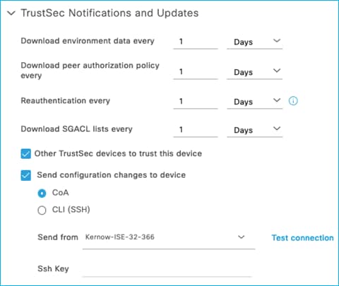
A wireless client is connected and assigned SGT 34 from ISE. Due to this, policies protecting SGT 34 are downloaded:
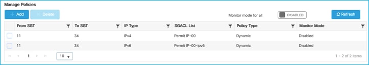
So, policy from SGT 11 to SGT 34 has been downloaded and the action is to permit traffic.
The permit can be seen to be honoured from the client and from the C9800 role-based counters (Monitoring > General > TrustSec):
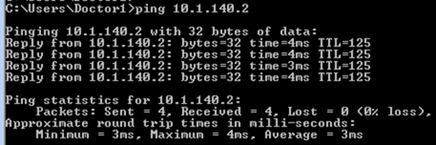
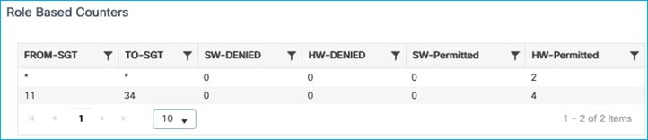
Now, use ISE to change the SGACL in use to be a deny instead of a permit and push the change to the C9800 (using CoA as per the ISE network device setting).
One way to edit the assigned SGACL in ISE is to find the cell in the policy matrix and select ‘Edit’ from the icon within the cell:
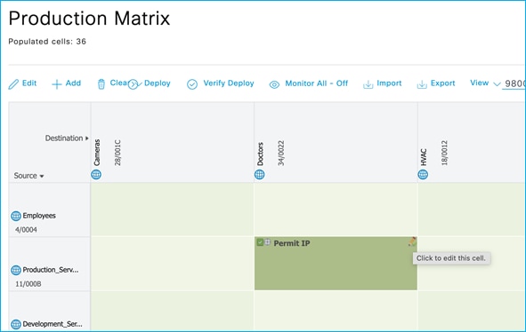
Then change the catch all rule Permit IP to a Deny IP:
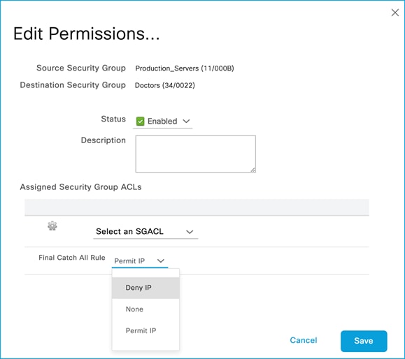
Save the change and use the ‘Deploy’ function at the top of the matrix to send the update to the network devices.
The client is blocked from communicating with the Production Server proving the policy update worked successfully:
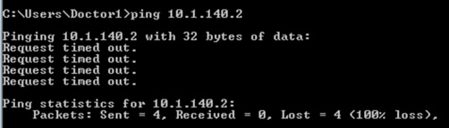
Policy updated in C9800:
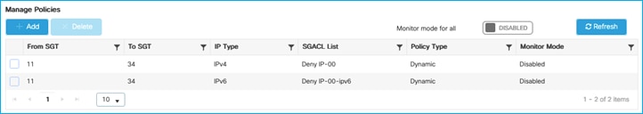
Hit counts on C9800 now showing denies:
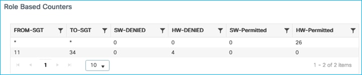
The policy can be updated successfully using CoA from ISE.
In ISE, navigate to Administration > Network Resources > Network Devices and edit the C9800 entry. Scroll down and ensure ‘Send configuration changes to device’ is set and CLI (SSH) is selected. Also ensure the C9800 access credentials are set correctly under ‘Device Configuration Deployment’:
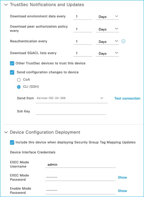
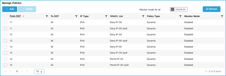
So, policy from SGT 11 to SGT 34 has been downloaded and the action is to deny traffic.
The deny can be seen to be honoured from the client and from the C9800 role-based counters (Monitoring > General > TrustSec):
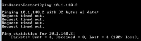
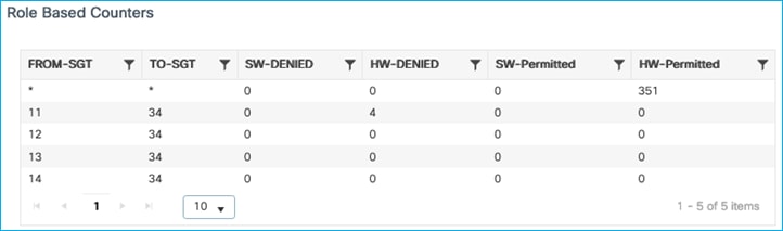
One way to edit the assigned SGACL in ISE is to find the cell in the policy matrix and select ‘Edit’ from the icon within the cell:
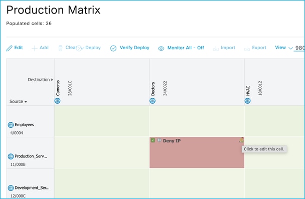
Then change the catch all rule Deny IP to a Permit IP:
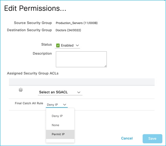
Save the change and use the ‘Deploy’ function at the top of the matrix to send the update to the network devices.
The client starts to communicate proving the policy update worked successfully:
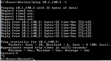
Policy updated in C9800:

Hit counts now showing permits:
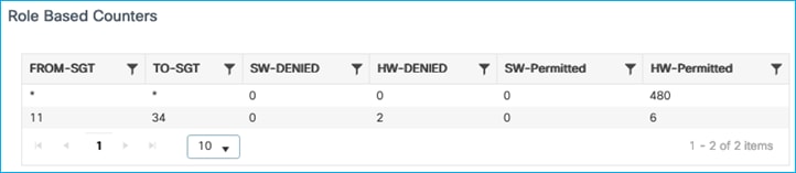
The policy can be updated successfully using SSH from ISE.
CoA and SSH for Policy Update on Flex AP
Flex Profile has SGACL enforcement enabled:
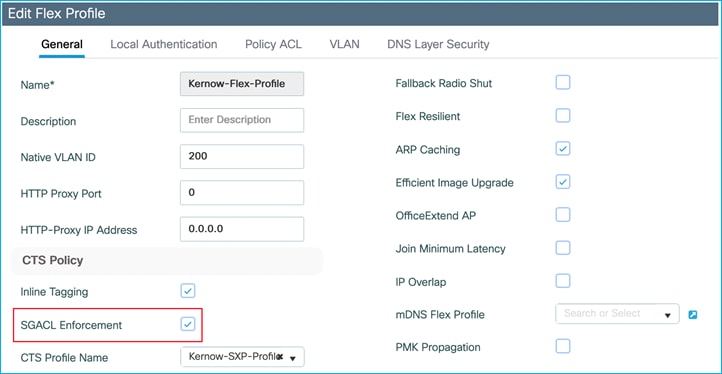
A wireless client is authenticated and authorized with Doctors SGT 34, as seen on the Flex AP:
AP0845.D132.75F8#show cts role-based sgt-map all
Active IPv4-SGT Bindings Information
IP SGT SOURCE
10.1.202.10 34 LOCAL
IP-SGT Active Bindings Summary
============================================
Total number of LOCAL bindings = 1
Total number of active bindings = 1
Active IPv6-SGT Bindings Information
IP SGT SOURCE
fe80::38c3:efb0:4c61:b920 34 LOCAL
IP-SGT Active Bindings Summary
============================================
Total number of LOCAL bindings = 1
Total number of active bindings = 1
A wired client is classified with SGT 33 and traffic is enforced on the Flex AP from 33 to 34 using SGACL DenyIPlog:
AP0845.D132.75F8#show cts role-based permissions
IPv4 role-based permissions:
SGT DGT ACL
11 34 Deny_IP
23 34 AllowDHCPDNS
33 34 DenyIPlog
AP0845.D132.75F8#show cts role-based counters from 33 to 34
IPv4 ACL: DenyIPlog
Packets Allowed : 0
Packets Denied : 930
IPv6 ACL: DenyIPlog
Packets Allowed : 0
Packets Denied : 0
Network Device entry in ISE for the C9800-CL is currently set to use CoA for policy updates (Administration > Network Resources > Network Devices). Scroll down and see ‘Send configuration changes to device’ is set and CoA is selected:

Now, change the policy in ISE to use the catch all rule of ‘Permit IP’ SGACL:
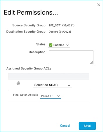
Deploy the change from ISE:
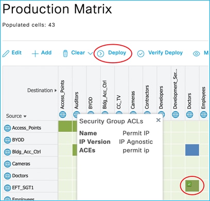
Policy from 33 (EFT_SGT1) to 34 (Doctors) is shown to have been updated on the Flex AP:
AP0845.D132.75F8#show cts role-based permissions
IPv4 role-based permissions:
SGT DGT ACL
11 34 Deny_IP
23 34 AllowDHCPDNS
33 34 Permit_IP
Policy on Flex AP is now permitting traffic:
AP0845.D132.75F8#show cts role-based counters from 33 to 34
IPv4 ACL: Permit_IP
Packets Allowed : 5
Packets Denied : 0
IPv6 ACL: Permit_IP
Packets Allowed : 0
Packets Denied : 0
This proves that using CoA for policy change works successfully for policy on a Flex AP.
Update the ISE Network Device entry for the 9800-CL to use SSH to push policy changes rather than using CoA:
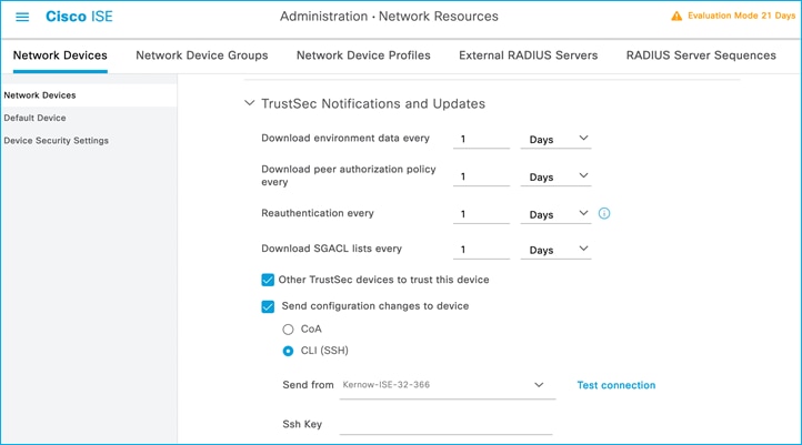
Again, change the policy in ISE from 33 (EFT_SGT1) to 34 (Doctors) but use ‘Deny IP’ as a final catch all SGACL rule:
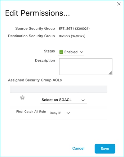
Deploy the policy change:
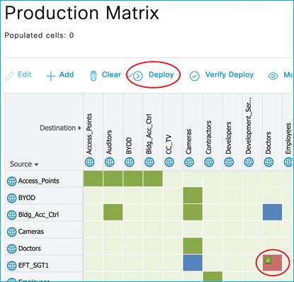
Flex AP shows policy has been changed from Permit IP to Deny IP:
AP0845.D132.75F8#show cts role-based permissions
IPv4 role-based permissions:
SGT DGT ACL
11 34 Deny_IP
23 34 AllowDHCPDNS
33 34 Deny_IP
IPv6 role-based permissions:
SGT DGT ACL
11 34 Deny_IP
23 34 AllowDHCPDNS
33 34 Deny_IP
Traffic is enforced from SGT 33 to 34:
AP0845.D132.75F8#show cts role-based counters from 33 to 34
IPv4 ACL: Deny_IP
Packets Allowed : 0
Packets Denied : 5
IPv6 ACL: Deny_IP
Packets Allowed : 0
Packets Denied : 0
So, CoA and SSH can be used from ISE to update any policy changes on the Flex AP’s. However, sometimes when there are multiple policy changes and therefore multiple CoA pushes, it has been seen that the C9800 controller running 17.9.1 does not always send policy updates to the APs. This is documented in the following DDTS: CSCwc15911 CoA changes are not reflecting in Flex mode APs for TrustSec
This is fixed in release 17.9.2.
Monitor Mode for Policy Entries
Monitor Mode is a function to allow policies to be pushed and downloaded to network devices, but traffic is always permitted. It is useful for visibility before full enforcement is enabled.
Monitor Mode on C9800 controller
There is an existing policy downloaded from ISE on this C9800 (as a wireless client is authorized with Doctors SGT 34):
Navigate to Configuration > Security > TrustSec > CTS Policies:
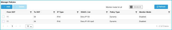
Initially tested that this policy was denying traffic from and endpoint with SGT 11 to the wireless client with SGT 34.
Now, in ISE, edit the policy cell and change it to monitor mode.
Click the edit icon in the corner of the matrix cell in ISE:
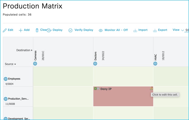
Then edit the policy by dropping the ‘Status’ function down and selecting ‘Monitor’:
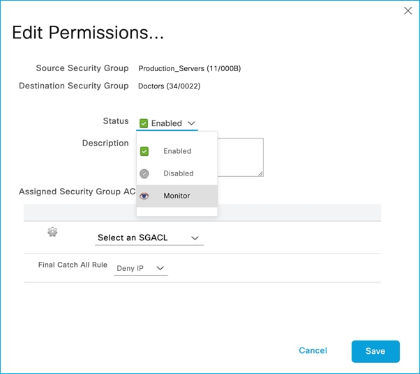
Save and Deploy the change using the Deploy function at the top of the matrix.
The C9800 shows the policy entries with Monitor Mode Enabled:
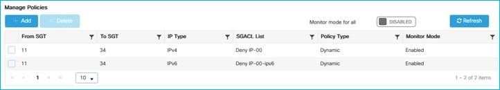
And a ping from wireless client to Production Server goes through:
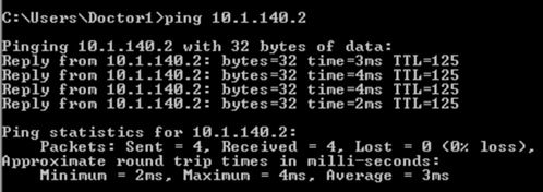
There are no role-based counters in the webui for Monitor Mode:
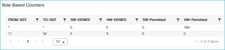
But you can see the Monitor counters via CLI in the C9800:
9800-17.9.1#show cts role-based counters
Role-based IPv4 counters
From To SW-Denied HW-Denied SW-Permitt HW-Permitt SW-Monitor HW-Monitor
* * 0 0 0 105 0 0
29 11 0 0 0 0 0 0
34 11 0 0 0 0 0 0
15 28 0 0 0 0 0 0
23 28 0 0 0 0 0 0
31 28 0 0 0 0 0 0
33 28 0 0 0 0 0 0
34 28 0 0 0 0 0 0
11 34 0 0 0 0 0 93
So, the function works but the CLI would currently need to be used for visibility. Counters are being introduced in the webui for Monitor Mode in release 17.11: CSCwc96257 WebUI: SGACL counters is not getting shown for Monitor mode in webui.
A second test is to use the C9800 function in the GUI to set ‘Monitor Mode for all’ under Configuration > Security > TrustSec > CTS Policies:
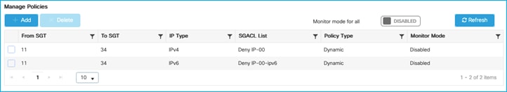
Click ‘Disabled’ after ‘Monitor Mode for all’ to set Enabled:
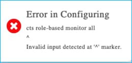
Additionally, the ‘Monitor Mode for all’ feature is not supported.
The following two DDTS entries were opened to track both these issues:
CSCwc96257 WebUI: SGACL counters is not getting shown for Monitor mode in webui.
CSCwd14088 C9800: The option to set CTS Policy Monitor mode for all generates an error.
Monitor Mode on Flex AP (Not Supported)
Flex AP is configured for SGACL enforcement (via Flex Profile):
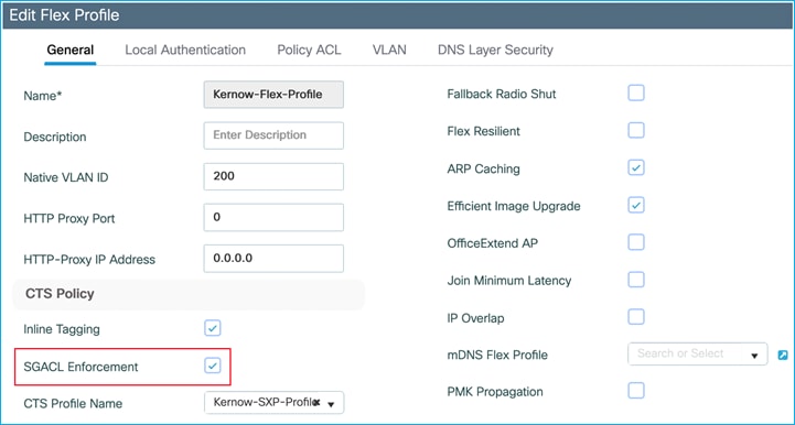
Enforcement is active from wired SGT 33 to wireless SGT 34:
AP0845.D132.75F8#show cts role-based permissions
IPv4 role-based permissions:
SGT DGT ACL
11 34 Deny_IP
23 34 AllowDHCPDNS
33 34 Deny_IP
IPv6 role-based permissions:
SGT DGT ACL
11 34 Deny_IP
23 34 AllowDHCPDNS
33 34 Deny_IP
AP0845.D132.75F8#show cts role-based counters from 33 to 34
IPv4 ACL: Deny_IP
Packets Allowed : 0
Packets Denied : 10
IPv6 ACL: Deny_IP
Packets Allowed : 0
Packets Denied : 0
Now, edit the policy in ISE and change it to Monitor Mode:
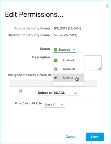
Deploy the change:
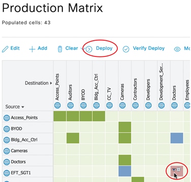
The policy is updated on the C9800 controller (Monitor Mode shown to be Enabled) for policy from SGT 33 to 34:
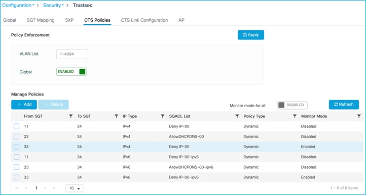
But the policy does not change on the AP:
AP0845.D132.75F8#show cts role-based permissions
IPv4 role-based permissions:
SGT DGT ACL
11 34 Deny_IP
23 34 AllowDHCPDNS
33 34 Deny_IP
IPv6 role-based permissions:
SGT DGT ACL
11 34 Deny_IP
23 34 AllowDHCPDNS
33 34 Deny_IP
The only impact is that the hit counters are reset on the Flex AP:
AP0845.D132.75F8#show cts role-based counters from 33 to 34
IPv4 ACL: Deny_IP
Packets Allowed : 0
Packets Denied : 3
IPv6 ACL: Deny_IP
Packets Allowed : 0
Packets Denied : 0
The conclusion is that Monitor Mode is not supported on the Flex AP’s.
Flex Access Point Propagation and Enforcement Scenarios
These flex use-cases use the following:
AP: 0845.d132.75f8, IPv4: 10.1.201.101
Client: 7cdd.90ee.992c, IPv4: 10.1.202.10
Policy Profile: Kernow-Flex_Policy
Flex Profile: Kernow-Flex-Profile
VLAN: Employee-Flex
WLAN and SSID: Kernow-Employees-Flex
On C9800 controller, navigate to Configuration > Security > TrustSec > AP.
Choose the associated Flex Profile and add an SXP connection peering with a separate enforcing network device. Make the AP end a Speaker and set a Default password:

Update and apply the change to the device.
Add the other half of the SXP connection on the enforcing device:
Kernow-C9k-top(config)#cts sxp enable
Kernow-C9k-top(config)#cts sxp default password xxxx
Kernow-C9k-top(config)#cts sxp conn peer 10.1.201.101 source 10.1.201.1 password default mode local listener
The SXP connection is ‘On’ or successfully connected as shown on the switch end:
Kernow-C9k-top#show cts sxp connections brief
SXP : Enabled
Highest Version Supported: 5
Default Password : Set
Default Key-Chain: Not Set
Default Key-Chain Name: Not Applicable
Default Source IP: Not Set
Connection retry open period: 120 secs
Reconcile period: 120 secs
Retry open timer is not running
Peer-Sequence traverse limit for export: Not Set
Peer-Sequence traverse limit for import: Not Set
----------------------------------------------------------------------------------------
Peer_IP Source_IP Conn Status Duration
----------------------------------------------------------------------------------------
10.1.201.101 10.1.201.1 On 0:00:01:36 (dd:hr:mm:sec)
Total num of SXP Connections = 1
A similar command can be run on the AP itself:
AP0845.D132.75F8#show cts sxp connections
SXP : Enabled
Highest Version Supported: 4
Default Password : Set
SXP Timers:
Connection retry open period:120
Reconcile period:120
Keepalive period:65535
Speaker minimum hold-time:120
Listener minimum hold-time:90
Listener maximum hold-time:120
SXP Connection Info:
peer #0: 10.1.201.1:64999
1 connection(s) active
connection status: successful
keepalive timer is armed
peer has listener role
1 configured peer(s)
Connect client to SSID Kernow-Employees-Flex, ISE assigns SGT Doctors 34.
The controller sends the IP:SGT mapping for the current client (10.1.202.10) to the AP:
AP0845.D132.75F8#show cts role-based sgt-map all
Active IPv4-SGT Bindings Information
IP SGT SOURCE
10.1.202.10 34 LOCAL
10.1.210.100 0 LOCAL
IP-SGT Active Bindings Summary
============================================
Total number of LOCAL bindings = 2
Total number of active bindings = 2
Active IPv6-SGT Bindings Information
IP SGT SOURCE
fe80::e586:d6cd:12be:f42c 34 LOCAL
IP-SGT Active Bindings Summary
============================================
Total number of LOCAL bindings = 1
Total number of active bindings = 1
This corresponds with the entry in the controller at Monitoring > General > TrustSec > IP – SGT Mappings:
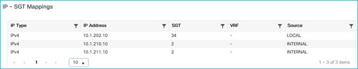
Due to the SXP connection being up from the AP to the Cat9k switch, we can see that client mapping has been sent to that switch (and learned via SXP):
Kernow-C9k-top#show cts role-based sgt-map all
Active IPv4-SGT Bindings Information
IP Address SGT Source
============================================
10.1.202.10 34 SXP
10.6.5.111 34 LOCAL
IP-SGT Active Bindings Summary
============================================
Total number of SXP bindings = 1
Total number of LOCAL bindings = 1
Total number of active bindings = 2
Active IPv6-SGT Bindings Information
IP Address SGT Source
================================================================
FE80::E586:D6CD:12BE:F42C 34 SXP
IP-SGT Active Bindings Summary
============================================
Total number of SXP bindings = 1
Total number of active bindings = 1
The client mapping can be used in enforcing traffic from/to the client in the Cat9k (the following example shows enforcing from SGT 11 to SGT 34):
Kernow-C9k-top#sh cts role counters
Role-based IPv4 counters
From To SW-Denied HW-Denied SW-Permitt HW-Permitt SW-Monitor HW-Monitor
* * 0 0 89 1578 0 0
29 11 0 0 0 0 0 0
11 34 0 3 0 0 0 0
33 34 0 0 0 0 0 0
So, the flex AP successfully propagates IP:SGT mappings via SXP
Enable inline tagging on Flex Profile (disable the SXP Profile to ensure SXP mappings do not interfere with the results):
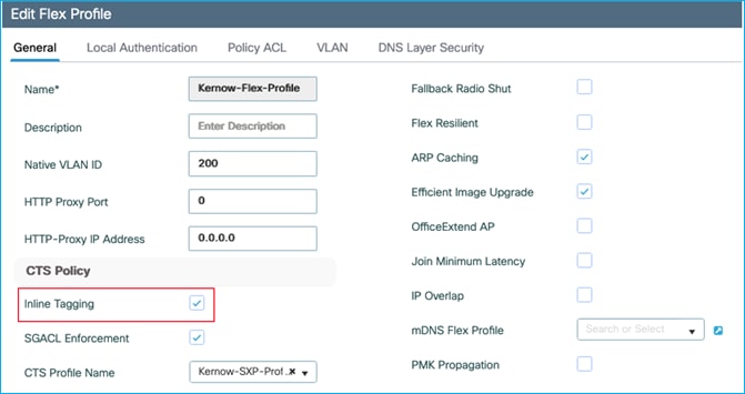
On interconnected switch (Cat9k), configure inline tagging to match:
interface GigabitEthernet1/0/18
switchport trunk native vlan 201
switchport trunk allowed vlan 201,202
switchport mode trunk
cts manual
policy static sgt 2 trusted
end
Authenticate a wireless client and assign an SGT from ISE:
AP0845.D132.75F8#sh cts role-based sgt-map all
Active IPv4-SGT Bindings Information
IP SGT SOURCE
10.1.202.10 34 LOCAL
Use monitor capture on the interconnected Cat9k to see if CMD is sent by the Flex AP. Send pings from wireless client to wired 10.4.21.1:
Cat9k receives SGT 34 in the CMD field so Flex AP is sending the SGT via inline tagging:
Kernow-C9k-top#show mon cap joff buff det | beg Frame 52
Frame 52: 86 bytes on wire (688 bits), 86 bytes captured (688 bits) on interface /tmp/epc_ws/wif_to_ts_pipe, id 0
Interface id: 0 (/tmp/epc_ws/wif_to_ts_pipe)
Interface name: /tmp/epc_ws/wif_to_ts_pipe
Encapsulation type: Ethernet (1)
Arrival Time: Aug 18, 2022 10:52:24.690760000 UTC
[Time shift for this packet: 0.000000000 seconds]
Epoch Time: 1660819944.690760000 seconds
[Time delta from previous captured frame: 0.268312000 seconds]
[Time delta from previous displayed frame: 0.268312000 seconds]
[Time since reference or first frame: 11.974915000 seconds]
Frame Number: 52
Frame Length: 86 bytes (688 bits)
Capture Length: 86 bytes (688 bits)
[Frame is marked: False]
[Frame is ignored: False]
[Protocols in frame: eth:ethertype:vlan:ethertype:cmd:ethertype:ip:icmp:data]
Ethernet II, Src: 7c:dd:90:ee:99:2c (7c:dd:90:ee:99:2c), Dst: 04:6c:9d:1f:88:42 (04:6c:9d:1f:88:42)
Destination: 04:6c:9d:1f:88:42 (04:6c:9d:1f:88:42)
Address: 04:6c:9d:1f:88:42 (04:6c:9d:1f:88:42)
.... ..0. .... .... .... .... = LG bit: Globally unique address (factory default)
.... ...0 .... .... .... .... = IG bit: Individual address (unicast)
Source: 7c:dd:90:ee:99:2c (7c:dd:90:ee:99:2c)
Address: 7c:dd:90:ee:99:2c (7c:dd:90:ee:99:2c)
.... ..0. .... .... .... .... = LG bit: Globally unique address (factory default)
.... ...0 .... .... .... .... = IG bit: Individual address (unicast)
Type: 802.1Q Virtual LAN (0x8100)
802.1Q Virtual LAN, PRI: 0, DEI: 0, ID: 202
000. .... .... .... = Priority: Best Effort (default) (0)
...0 .... .... .... = DEI: Ineligible
.... 0000 1100 1010 = ID: 202
Type: CiscoMetaData (0x8909)
Cisco MetaData
Version: 1
Length: 1
Options: 0x0001
SGT: 34
Type: IPv4 (0x0800)
Internet Protocol Version 4, Src: 10.1.202.10, Dst: 10.4.21.1
0100 .... = Version: 4
.... 0101 = Header Length: 20 bytes (5)
Differentiated Services Field: 0x00 (DSCP: CS0, ECN: Not-ECT)
0000 00.. = Differentiated Services Codepoint: Default (0)
.... ..00 = Explicit Congestion Notification: Not ECN-Capable Transport (0)
Total Length: 60
Identification: 0x3711 (14097)
Flags: 0x0000
0... .... .... .... = Reserved bit: Not set
.0.. .... .... .... = Don't fragment: Not set
..0. .... .... .... = More fragments: Not set
Fragment offset: 0
Time to live: 128
Protocol: ICMP (1)
Header checksum: 0x10a0 [validation disabled]
[Header checksum status: Unverified]
Source: 10.1.202.10
Destination: 10.4.21.1
Internet Control Message Protocol
Type: 8 (Echo (ping) request)
Code: 0
Checksum: 0x4cd8 [correct]
[Checksum Status: Good]
Identifier (BE): 1 (0x0001)
Identifier (LE): 256 (0x0100)
Sequence number (BE): 131 (0x0083)
Sequence number (LE): 33536 (0x8300)
Data (32 bytes)
If policy exists in the Cat9k to enforce from wireless to wired (Doctors 34 to Production_Servers 11)
Kernow-C9k-top#show cts role-based permissions
IPv4 Role-based permissions default:
Permit IP-00
IPv4 Role-based permissions from group 34:Doctors to group 11:Production_Servers:
Deny IP-00
RBACL Monitor All for Dynamic Policies : FALSE
RBACL Monitor All for Configured Policies : FALSE
Then the Cat9k switch enforces using the source SGT lookup of CMD from the Flex AP:
Kernow-C9k-top#sh cts role-based counters
Role-based IPv4 counters
From To SW-Denied HW-Denied SW-Permitt HW-Permitt SW-Monitor HW-Monitor
* * 0 0 29 349 0 0
34 11 0 4 0 0 0 0
Note: the inline tagging setting on the Policy Profile is irrelevant, it’s the setting on the Flex Profile which is used to determine if inline tagging is enabled or not on the Flex AP.
This use-case is to ensure the flex AP can enforce traffic using a source SGT learned from SXP and a destination SGT learned from an authenticated client.
Setup an SXP connection from a Cat9k switch to an AP in Flex Mode.
In the C9800 webui, navigate to Configuration > Security > TrustSec > AP and either add a new SXP Profile or change the existing one. In this example we will set the Cat9k to be the Speaker and the AP the Listener.
Under the SXP Profile, ensure a default password is set and delete any existing SXP Connections. Add a new SXP Connection on the AP peering with the Cat9k (10.1.201.1) but make the AP a Listener so the AP can receive mappings and use them for enforcement:
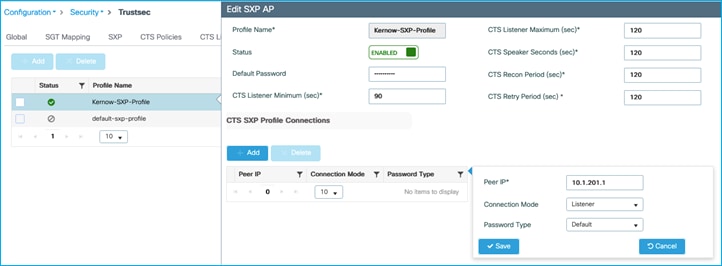
Save the change and then Update and apply the changes to the device.
Now, change the Cat9k end of the SXP connection to ensure it is sending mappings (set as Speaker) to the AP.
Remove any existing SXP connections on the Cat9k, then add a new connection:
Kernow-C9k-top(config)#cts sxp enable
Kernow-C9k-top(config)#cts sxp default password xxxx
Kernow-C9k-top(config)#cts sxp connection peer 10.1.201.101 source 10.1.201.1 password default mode local speaker
Cat9k end shows the connection is up or ‘on’:
Kernow-C9k-top#show cts sxp connections brief
SXP : Enabled
Highest Version Supported: 5
Default Password : Set
Default Key-Chain: Not Set
Default Key-Chain Name: Not Applicable
Default Source IP: Not Set
Connection retry open period: 120 secs
Reconcile period: 120 secs
Retry open timer is not running
Peer-Sequence traverse limit for export: Not Set
Peer-Sequence traverse limit for import: Not Set
----------------------------------------------------------------------------------------
Peer_IP Source_IP Conn Status Duration
----------------------------------------------------------------------------------------
10.1.201.101 10.1.201.1 On 0:00:00:58 (dd:hr:mm:sec)
Total num of SXP Connections = 1
AP shows the connection successful:
AP0845.D132.75F8#sh cts sxp connections
SXP : Enabled
Highest Version Supported: 4
Default Password : Set
SXP Timers:
Connection retry open period:120
Reconcile period:120
Keepalive period:65535
Speaker minimum hold-time:120
Listener minimum hold-time:90
Listener maximum hold-time:120
SXP Connection Info:
peer #0: 10.1.201.1:64999
1 connection(s) active
connection status: successful
hold timer is armed
peer has speaker role
1 configured peer(s)
Firstly, a policy will be added to deny traffic from Production_Servers SGT 11 to Doctors SGT 34.
Now, a wireless client will be connected and assigned an SGT of Doctors 34 on the AP. The AP should download policies from the controller/ISE that are destined for the Doctors SGT.
We will classify traffic from a Production_Server (IP 10.4.21.1) with SGT 11 and send that classification through SXP to the AP and test if the AP enforces the communication.
Flex Profile > General (SGACL Enforcement is enabled):
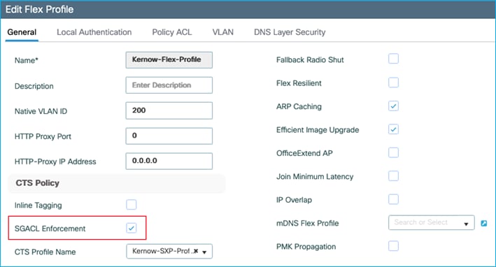
Flex Profile > VLAN (local VLAN 202):
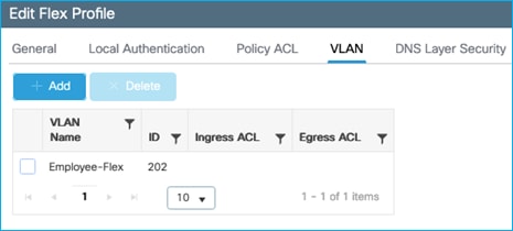
In ISE, add a policy to deny traffic from Production_Servers SGT 11 to Doctors SGT 34:
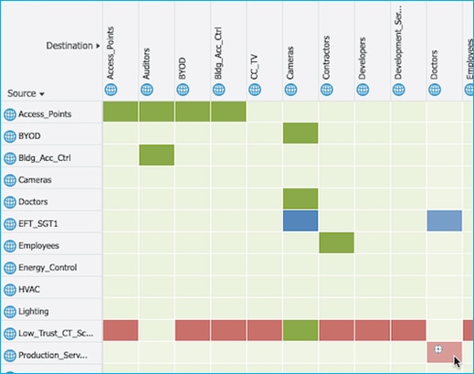
Now, connect wireless client.
The AP shows ISE has assigned SGT 34 for the wireless client (10.1.202.10):
AP0845.D132.75F8#show cts role-based sgt-map all
Active IPv4-SGT Bindings Information
IP SGT SOURCE
1.1.1.6 2 SXP
10.1.201.1 2 SXP
10.1.202.1 2 SXP
10.1.202.10 34 LOCAL
10.3.25.2 2 SXP
10.4.21.2 2 SXP
10.6.5.111 34 SXP
10.6.5.254 2 SXP
IP-SGT Active Bindings Summary
============================================
Total number of LOCAL bindings = 1
Total number of SXP bindings = 7
Total number of active bindings = 8
Active IPv6-SGT Bindings Information
IP SGT SOURCE
fe80::e586:d6cd:12be:f42c 34 LOCAL
IP-SGT Active Bindings Summary
============================================
Total number of LOCAL bindings = 1
Total number of active bindings = 1
The controller then downloads the policies protecting that SGT, and passes them to the AP:
AP0845.D132.75F8#show cts role-based permissions
IPv4 role-based permissions:
SGT DGT ACL
11 34 Deny_IP
33 34 DenyIPlog
65535 65535 Permit_IP
IPv6 role-based permissions:
SGT DGT ACL
11 34 Deny_IP
33 34 DenyIPlog
65535 65535 Permit_IP
To test whether the Flex AP enforces from an SXP mapping towards a wireless client, add a mapping for a wired endpoint 10.4.21.1 into the Cat9k and send it to the AP via the SXP connection.
Add mapping on Cat9k:
Kernow-C9k-top(config)#cts role-based sgt-map 10.4.21.1 sgt 11
Can see it’s received by the AP via SXP:
AP0845.D132.75F8#sh cts role sgt-map all
Active IPv4-SGT Bindings Information
IP SGT SOURCE
1.1.1.6 2 SXP
10.1.201.1 2 SXP
10.1.202.1 2 SXP
10.1.202.10 34 LOCAL
10.3.25.2 2 SXP
10.4.21.1 11 SXP
10.4.21.2 2 SXP
10.6.5.111 34 SXP
10.6.5.254 2 SXP
169.254.244.44 0 LOCAL
IP-SGT Active Bindings Summary
============================================
Total number of LOCAL bindings = 2
Total number of SXP bindings = 8
Total number of active bindings = 10
Active IPv6-SGT Bindings Information
IP SGT SOURCE
fe80::e586:d6cd:12be:f42c 34 LOCAL
IP-SGT Active Bindings Summary
============================================
Total number of LOCAL bindings = 1
Total number of active bindings = 1
And traffic is enforced from wired endpoint to wireless:
AP0845.D132.75F8#show cts role-based counters from 11 to 34
IPv4 ACL: Deny_IP
Packets Allowed : 0
Packets Denied : 5
IPv6 ACL: Deny_IP
Packets Allowed : 0
Packets Denied : 0
____________
Why is there enforcement settings on both Flex Profile and Policy Profile, and which one takes precedence?
The test above has enforcement set on both.
Now, test by disabling enforcement on the Flex Profile and leaving enabled on the Policy Profile. Client authenticates, a mapping is seen on the AP, but no policy is downloaded:
AP0845.D132.75F8#show cts role-based permissions
IPv4 role-based permissions:
SGT DGT ACL
IPv6 role-based permissions:
SGT DGT ACL
Now, test enforcement enabled on Flex Profile and disabled on Policy Profile:
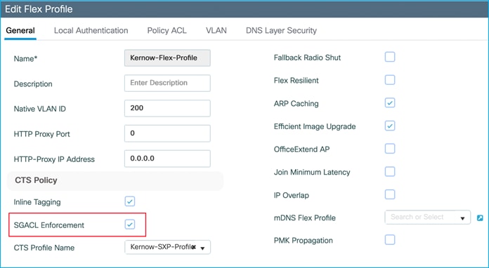
Disabled on Policy Profile:
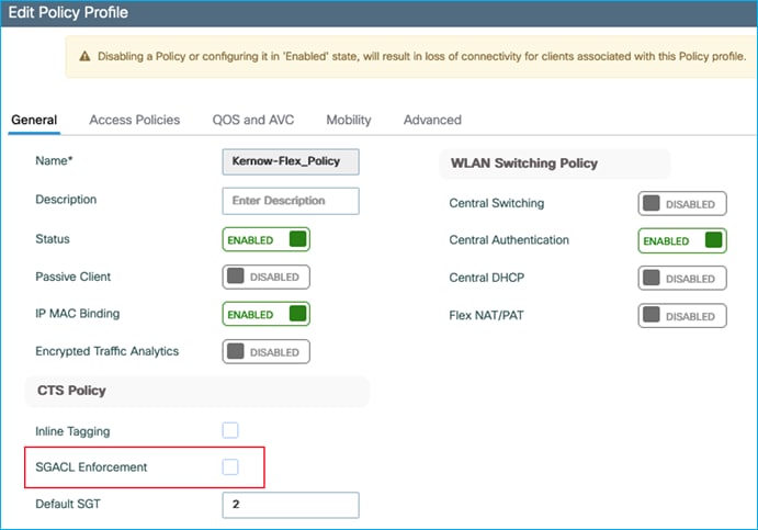
Note: Central switching is disabled, and central authentication enabled. DHCP is also using an IP-helper on the local switch SVI, not central.
Re-auth the client, a mapping is seen on the AP, and this time policy is downloaded:
AP0845.D132.75F8#sh cts role-based permissions
IPv4 role-based permissions:
SGT DGT ACL
11 34 Deny_IP
33 34 DenyIPlog
IPv6 role-based permissions:
SGT DGT ACL
11 34 Deny_IP
33 34 DenyIPlog
Conclusion: the enforcement setting in the Flex Profile is the setting to control enforcement on the Flex AP.
Note: the use-case above is enforcing North to South, for example, wired to wireless. When the wireless client authenticates, this is through the C9800 controller and therefore the C9800 controller knows to download policy and send that policy to the AP.
Note: In the South to North direction, for example trying to enforce wireless to wired on the Flex AP, a policy would be required protecting the mapping received from SXP. In this scenario, the C9800 controller is not aware of the mappings received by the Flex AP and hence, no policy is downloaded by the C9800 controller and therefore no policy is sent to the AP.
Note: To summarize, the Flex AP can only enforce from North to South (wired to wireless), not South to North (wireless to wired). If South to North enforcement is required, then propagate the wireless source SGT northbound using SXP or inline tagging/CMD to enforce on another platform.
Flex AP Enforcing from Inline (CMD)
Set inline tagging on the Flex Profile; also enable enforcement as we want to enforce North to South (wired to wireless) in this use-case:
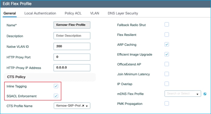
Ensure the SXP Profile is disabled so SXP mappings do not interfere with the results.
Set inline tagging on the interconnected Cat9k switch to ensure the point-to-point link between Cat9k switch and Flex AP is sending CMD:
interface GigabitEthernet1/0/18
switchport trunk native vlan 201
switchport trunk allowed vlan 201,202
switchport mode trunk
cts manual
policy static sgt 2 trusted
end
Authenticate a wireless endpoint and assign an SGT from ISE:
AP0845.D132.75F8#sh cts role-based sgt-map all
Active IPv4-SGT Bindings Information
IP SGT SOURCE
10.1.202.10 34 LOCAL
IP-SGT Active Bindings Summary
============================================
Total number of LOCAL bindings = 1
Total number of active bindings = 1
Active IPv6-SGT Bindings Information
IP SGT SOURCE
fe80::e586:d6cd:12be:f42c 34 LOCAL
IP-SGT Active Bindings Summary
============================================
Total number of LOCAL bindings = 1
Total number of active bindings = 1
ISE has a policy to deny traffic from Production_Servers SGT 11 to Doctors SGT 34:
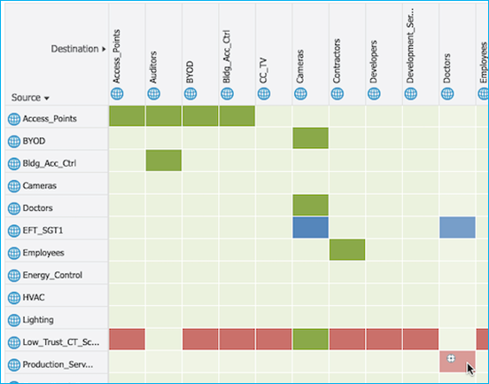
So, C9800 controller downloads the policies to protect destination SGT 34 and sends them to the Flex AP:
AP0845.D132.75F8#sh cts role-based permissions
IPv4 role-based permissions:
SGT DGT ACL
11 34 Deny_IP
33 34 DenyIPlog
IPv6 role-based permissions:
SGT DGT ACL
11 34 Deny_IP
33 34 DenyIPlog
Traffic from my wired client 10.4.21.1 is enforced destined towards the wireless client 10.1.202.10:
AP0845.D132.75F8#show cts role-based counters from 11 to 34
IPv4 ACL: Deny_IP
Packets Allowed : 0
Packets Denied : 5
IPv6 ACL: Deny_IP
Packets Allowed : 0
Packets Denied : 0
This proves that the Flex AP can carry out a source lookup from received CMD and enforce towards a wireless client.
Note: the inline tagging setting on the Policy Profile is irrelevant when enabling inline tagging on the Flex AP. It is the setting on the Flex Profile which enables or disables this feature.
Download Environment-Data and Policy Using HTTPS
The primary intent of this feature is to address transport, reliability and resiliency concerns with RADIUS and move towards a reliable and extensible approach to source SGACL policies and Environment-Data from ISE.
This use case tests the HTTPS download function on the C9800.
In ISE, enable HTTP Service under Work Centers > TrustSec > Settings > General TrustSec Settings:

Save the change.
Then, under Work Centers > TrustSec > Components > TrustSec Servers > HTTPS Servers, click ‘Manage PSN Servers’:
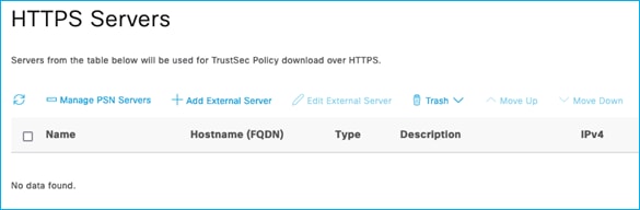
Select the PSN that is used by the C9800 controller and click on Save.
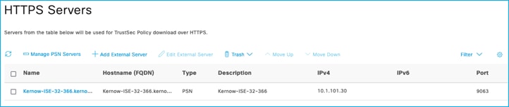
Navigate to the C9800 controller network device in ISE via Administration > Network Resources > Network Devices, click on the C9800 controller network device entry.
Scroll down to Advanced TrustSec Settings, enable HTTP REST API and enter credentials for HTTP REST API settings:
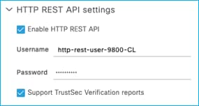
Note: Currently this username must be different per network device within an ISE deployment.
Save the change.
In ISE, export the ISE Admin certificate public keys for your ISE PSN node(s)
(Administration > System > Certificates)
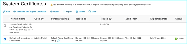
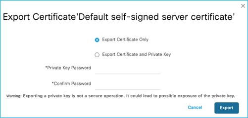
Click Export and save the pem file locally.
On the C9800 controller:
9800-17.9.1#conf t
Enter configuration commands, one per line. End with CNTL/Z.
9800-17.9.1(config)#crypto pki trustpoint ISE-REST
9800-17.9.1(ca-trustpoint)#enrollment mode ra
9800-17.9.1(ca-trustpoint)#enrollment terminal
9800-17.9.1(ca-trustpoint)#usage ssl-client
9800-17.9.1(ca-trustpoint)#revocation-check none
9800-17.9.1(ca-trustpoint)#exit
Open the pem file saved locally from the ISE export and copy the entirety of the contents.
On the C9800 controller:
9800-17.9.1(config)#crypto pki authenticate ISE-REST
Enter the base 64 encoded CA certificate.
End with a blank line or the word "quit" on a line by itself
Note: Paste the copied pem file here, as follows:
-----BEGIN CERTIFICATE-----
MIIFWjCCA0KgAwIBAgIMNX0ZYC/oELoCLNCfMA0GCSqGSIb3DQEBDAUAMCcxJTAj
BgNVBAMTHEtlcm5vdy1JU0UtMzItMzY2Lmtlcm5vdy5jb20wHhcNMjIwNjE2MTU0
MTQ4WhcNMjQwNjE1MTU0MTQ4WjAnMSUwIwYDVQQDExxLZXJub3ctSVNFLTMyLTM2
Ni5rZXJub3cuY29tMIICIjANBgkqhkiG9w0BAQEFAAOCAg8AMIICCgKCAgEAvq07
Sd/QLn+WCBozYvV5ymgeWuRBjzYai1ymBcvnUNV5Dh9rtiBcXSF3aLvnbsaaCuqm
nXn9Q1OITBJvcdnU/hf7N/5D44nWHshzasBxfBVxpcrl+8FbQpj9qzoCeRg7Ph9n
48qvDAwTp4inzc9k4n9ShTv88woKhek7ewRU7b+VcEWciJr6MU/731RxC7B1E8y8
aUMFSBwkEZiq0ibmEMbiY/uKFF33X2E5rht/Dmt3V7H3ngENtuVD0+OZx4wCyHmA
CiumZpZvyoXh3jF/mK5VI1O9GSihwe6xHZiQQUMbwG/FSRWP8NF/Vi7n52721Ssh
nH+ygtGfIKsNAHdfLXqpEhcIoCxjxMlb+En58mEVJI53d9w0qh7Ge42i58s3dqW0
k5L5HckVW1mKpCOZppSGX/vBPGBlzzGH9bazibRSi4n4FBgJvKdzJd2QV3NgQuos
t0xRJFhWurWupDmeZpQgFSZYukpzivz9+dJ6x1KQYQpGIjIGZLn3LhQ/WGsa1PSV
yLm1mt0hJsQBvDyeoRWqFL0PHoHkaXCGl7WMy2GB3B3uqn1dQ7q8HdvQHO4emWCd
9+QnEXqgPR44jZw7skRZ/9aTZYgZ5M6P5Bx4AXqH7BAyhYQtgwSUco5nzcAjO3al
Z0Jrw5HMn5i21JwTGomk1McfasF/nHGJuwoS8u8CAwEAAaOBhTCBgjAnBgNVHREE
IDAeghxLZXJub3ctSVNFLTMyLTM2Ni5rZXJub3cuY29tMAwGA1UdEwQFMAMBAf8w
CwYDVR0PBAQDAgLsMB0GA1UdDgQWBBSy2QLr72Ey1GgbX5WnYEJfibrFEjAdBgNV
HSUEFjAUBggrBgEFBQcDAQYIKwYBBQUHAwIwDQYJKoZIhvcNAQEMBQADggIBADAh
1tCxmgLN0yLQg4XKynk9hr/djdbE9SWBr3JQWJjKmTG3+QrxJ+w/v9m6ABikN5EN
vkrI9tQ5GHzNG9filS1RNG6ZhcCD3Ht85wBd1sjwu2iTGwAldQRnOiaTWCBvFn3w
B6r6dDoVq149q4HAno/CJpNsxU1UoL7ifrL9HLWkYqbRqBx/0HY0Z8RZrzUp8izZ
u0jLtC0GHlp386KcsKLWhFApSa+YvuI0fiinGGbRvOGO9/BTSwtqsA4ZjAdeTYWt
o297G2XfUQ6FA5nS/RnGwWEFp1sn9oLrrafeDHNxCh2UG5XDingI3Bp+hY0FByyy
ZK7Pf8UIH/Hmmx+xX7I9l4K6S6MQulWNG10bjfsu9DxNIZmIQwZouyTP99hfKbw4
oI4pLHuXJlZOv6fuzkuhgRR60sPugSFTIB5thWUXBRafNHhFjKlzugt4FOQDvRQr
zehiCCK9gyy5teSNV9/bNLnlzGY6ss6KdYRxybvVSrINiUhoHRCzk6gHS3BTdzwC
j7Z6gNuwateI0vQnT8XE7FN+u4hbaUk72LExbghIicZDyovzbfXQXYSZx46guRZY
ZiRTU0JYfgbOCu+c5FkzFMbyKcCuoMr5JTQ0+SZVhG2nWa5Edir6EHqfhrrnFHry
/HbuPm6iA5ht2KE2MUJDpu9euKrUQC0yu3N3fl4Y
-----END CERTIFICATE-----
quit
Certificate has the following attributes:
Fingerprint MD5: DB2AA78C 375B6ECE F28FFE5F CCDDF3FE
Fingerprint SHA1: 4EBBD588 778E261A 382C9D00 44691DAF E092506E
% Do you accept this certificate? [yes/no]: yes
Trustpoint CA certificate accepted.
% Certificate successfully imported
Remove the cts authorization list in the C9800 controller config to switch over from using RADIUS to using HTTPS REST:
9800-17.9.1(config)#no cts authorization list CTS-Authz-List
9800-17.9.1(config)#no aaa authorization network CTS-Authz-List group RADIUS_SERVER_GROUP_DAY0
Add the policy download configuration:
9800-17.9.1(config)#cts policy-server name ISE-REST
9800-17.9.1(config-policy-server)#address ipv4 10.1.101.30
9800-17.9.1(config-policy-server)#address domain-name ISE-REST.kernow.com
9800-17.9.1(config-policy-server)#port 9063
9800-17.9.1(config-policy-server)#tls server-trustpoint ISE-REST
9800-17.9.1(config-policy-server)#retransmit 3
9800-17.9.1(config-policy-server)#timeout 15
9800-17.9.1(config-policy-server)#content-type json
9800-17.9.1(config-policy-server)#exit
9800-17.9.1(config)#cts policy-server username http-rest-user-9800-CL password 0 xxxx
9800-17.9.1(config)#cts policy-server device-id 9800-CL
9800-17.9.1(config)#cts environment-data enable
9800-17.9.1#show cts policy-server details all
Server Name : ISE-REST
Server Status : Inactive
IPv4 Address : 10.1.101.30 (Reachable)
Domain-name : ISE-REST.kernow.com (Reachable)
Trustpoint : ISE-REST
Port-num : 9063
Retransmit count : 3
Timeout : 15
App Content type : JSON
Trustpoint chain : NOT CONFIGURED
Server Name : Kernow-ISE-32-366.kernow.com
Server Status : Active
IPv4 Address : 10.1.101.30 (Reachable)
Domain-name : Kernow-ISE-32-366.kernow.com (Reachable)
Trustpoint : cts_tp_Kernow-ISE-32-366.kernow.com_0
Port-num : 9063
Retransmit count : 3
Timeout : 15
App Content type : JSON
Trustpoint chain : NOT CONFIGURED
After clearing previous PACs and environment-data, environment-data is re-downloaded (via HTTPS REST) without requiring a PAC:
9800-17.9.1#show cts pacs
No PACs found in the key store.
9800-17.9.1#show cts environment-data
CTS Environment Data
====================
Current state = COMPLETE
Last status = Successful
Service Info Table:
Local Device SGT:
SGT tag = 2:TrustSec_Devices
Server List Info:
Security Group Name Table:
0-01:Unknown
2-01:TrustSec_Devices
3-02:Network_Services
…etc
When new policy is added in ISE, it is downloaded successfully without RADIUS being displayed in the ISE Live Log. This tests prove HTTPS can be used instead of RADIUS for environment-data and Policy download from ISE.
High Availability Operation With SGTs
HA Setup
On standby C9800, use the following CLI command to change the chassis number to 2:
9800-17.9.1HA#chassis 1 renumber 2
Then reload
Then, used the GUI:
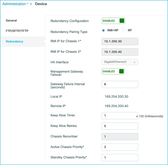
Then reloaded again.
To enable console access on the standby, enter the following command on the active:
redundancy
mode sso
main-cpu
standby console enable
Relevant config shown on the active:
mode sso
main-cpu
standby console enable
!
interface Vlan200
ip address 10.1.200.30 255.255.255.0 secondary
ip address 10.1.200.10 255.255.255.0
!
redun-management interface Vlan200 chassis 1 address 10.1.200.30 chassis 2 address 10.1.200.40
Relevant config on the standby C9800:
!
redundancy
mode sso
main-cpu
standby console enable
!
interface Vlan200
ip address 10.1.200.40 255.255.255.0
!
redun-management interface Vlan200 chassis 1 address 10.1.200.30 chassis 2 address 10.1.200.40
Note: 10.1.200.10 under vlan200 is the management IP. This is the IP that we terminate SXP connections on. Upon failover, this management IP is available on the new active platform and remote access is still possible and SXP connections remain up.
9800-17.9.1#show chassis
Chassis/Stack Mac Address : 0050.56b2.f56e - Local Mac Address
Mac persistency wait time: Indefinite
H/W Current
Chassis# Role Mac Address Priority Version State IP
-------------------------------------------------------------------------------------
*1 Active 0050.56b2.f56e 2 V02 Ready 169.254.200.30
2 Standby 0050.56b2.6155 1 V02 Ready 169.254.200.40
9800-17.9.1#show redundancy
Redundant System Information :
------------------------------
Available system uptime = 55 minutes
Switchovers system experienced = 0
Standby failures = 0
Last switchover reason = none
Hardware Mode = Duplex
Configured Redundancy Mode = sso
Operating Redundancy Mode = sso
Maintenance Mode = Disabled
Communications = Up
Current Processor Information :
-------------------------------
Active Location = slot 1
Current Software state = ACTIVE
Uptime in current state = 55 minutes
Image Version = Cisco IOS Software [Cupertino], C9800-CL Software (C9800-CL-K9_IOSXE), Version 17.9.1eft15, RELEASE SOFTWARE (fc1)
Technical Support: http://www.cisco.com/techsupport
Copyright (c) 1986-2022 by Cisco Systems, Inc.
Compiled Fri 24-Jun-22 20:01 by mcpre
BOOT = bootflash:packages.conf,12;
Configuration register = 0x2102
Recovery mode = Not Applicable
Fast Switchover = Enabled
Initial Garp = Enabled
Peer Processor Information :
----------------------------
Standby Location = slot 2
Current Software state = STANDBY HOT
Uptime in current state = 53 minutes
Image Version = Cisco IOS Software [Cupertino], C9800-CL Software (C9800-CL-K9_IOSXE), Version 17.9.1eft15, RELEASE SOFTWARE (fc1)
Technical Support: http://www.cisco.com/techsupport
Copyright (c) 1986-2022 by Cisco Systems, Inc.
Compiled Fri 24-Jun-22 20:01 by mcpre
BOOT = bootflash:packages.conf,12;
CONFIG_FILE =
Configuration register = 0x2102
| Retrieved from Active C9800 |
Retrieved from Standby C9800 |
| 9800-17.9.1#sh cts pacs AID: AF8B97E848CC486737DFC8124B7F00AD PAC-Info: PAC-type = Cisco Trustsec AID: AF8B97E848CC486737DFC8124B7F00AD I-ID: 9800-CL A-ID-Info: Identity Services Engine Credential Lifetime: 10:44:32 British Oct 4 2022 PAC-Opaque: 000200B00… Refresh timer is set for 6w3d
|
9800-17.9.1-stby#sh cts pacs This command is disabled on standby units.
Note: PACs are not shared and are acquired on the new active C9800 immediately after switchover
|
| 9800-17.9.1#sh cts environment-data CTS Environment Data ==================== Current state = COMPLETE Last status = Successful Service Info Table: Local Device SGT: SGT tag = 2-01:TrustSec_Devices Server List Info: Installed list: CTSServerList1-0001, 1 server(s): *Server: 10.1.101.30, port 1812, A-ID AF8B97E848CC486737DFC8124B7F00AD Status = ALIVE auto-test = TRUE, keywrap-enable = FALSE, idle-time = 60 mins, deadtime = 20 secs Security Group Name Table: 0-00:Unknown 2-00:TrustSec_Devices 3-01:Network_Services 4-01:Employees 5-02:Contractors 6-01:Guests 7-01:Production_Users 8-01:Developers 9-02:Auditors 10-01:Point_of_Sale_Systems 11-10:Production_Servers 12-03:Development_Servers 13-00:Test_Servers 14-01:PCI_Servers 15-02:BYOD 16-00:Intranet 17-00:Extranet 18-02:HVAC 19-02:Lighting 20-02:Water_Control 21-00:Entertainment_Systems 22-01:CC_TV 23-02:Bldg_Acc_Ctrl 24-00:Intruder_Detection 25-02:Energy_Control 27-02:IP_Phones 28-09:Cameras 29-01:Access_Points 30-00:High_Trust_CT_Scanners 31-00:Low_Trust_CT_Scanners 32-01:Wireless_Clients 33-00:EFT_SGT1 34-39:Doctors 35-01:Storage 36-08:Scanners 37-00:Nurses 255-00:Quarantined_Systems 39-00:PLC_Siemens 40-00:WLCs Environment Data Lifetime = 86400 secs Last update time = 11:55:49 British Thu Aug 18 2022 Env-data expires in 0:22:26:37 (dd:hr:mm:sec) Env-data refreshes in 0:22:26:37 (dd:hr:mm:sec) Cache data applied = NONE State Machine is running Retry_timer (60 secs) is not running |
9800-17.9.1-stby#sh cts environment-data CTS Environment Data ==================== Current state = COMPLETE Last status = Successful Service Info Table: Local Configured Device SGT: 2:TrustSec_Devices Server List Info: Installed list: CTSServerList1-0001, 1 server(s): Server: 10.1.101.30, port 1812, A-ID AF8B97E848CC486737DFC8124B7F00AD Status = ALIVE auto-test = FALSE, keywrap-enable = FALSE, idle-time = 60 mins, deadtime = 20 secs Security Group Name Table: 0-00:Unknown 2-00:TrustSec_Devices 3-01:Network_Services 4-01:Employees 5-02:Contractors 6-01:Guests 7-01:Production_Users 8-01:Developers 9-02:Auditors 10-01:Point_of_Sale_Systems 11-10:Production_Servers 12-03:Development_Servers 13-00:Test_Servers 14-01:PCI_Servers 15-02:BYOD 16-00:Intranet 17-00:Extranet 18-02:HVAC 19-02:Lighting 20-02:Water_Control 21-00:Entertainment_Systems 22-01:CC_TV 23-02:Bldg_Acc_Ctrl 24-00:Intruder_Detection 25-02:Energy_Control 27-02:IP_Phones 28-09:Cameras 29-01:Access_Points 30-00:High_Trust_CT_Scanners 31-00:Low_Trust_CT_Scanners 32-01:Wireless_Clients 33-00:EFT_SGT1 34-39:Doctors 35-01:Storage 36-08:Scanners 37-00:Nurses 255-00:Quarantined_Systems 39-00:PLC_Siemens 40-00:WLCs Environment Data Lifetime = 86400 secs Last update time = 11:55:49 British Thu Aug 18 2022 Env-data expires in 0:22:26:10 (dd:hr:mm:sec) Env-data refreshes in 0:22:26:10 (dd:hr:mm:sec) Cache data applied = NONE State Machine is running Retry_timer (60 secs) is not running
|
| 9800-17.9.1#sh cts role-based sgt-map all Active IPv4-SGT Bindings Information
IP Address SGT Source ================================ 1.1.1.8 2 SXP 10.1.200.1 2 SXP 10.1.210.1 2 SXP 10.1.210.10 2 INTERNAL 10.1.210.100 34 LOCAL 10.1.211.1 2 SXP 10.1.211.10 2 INTERNAL 10.3.23.2 2 SXP 10.4.25.2 2 SXP 10.6.50.100 28 SXP 10.6.50.254 2 SXP
IP-SGT Active Bindings Summary =================================== Total number of SXP bindings = 8 Total number of LOCAL bindings = 1 Total number of INTERNAL bindings = 2 Total number of active bindings = 11
Active IPv6-SGT Bindings Information
IP Address SGT Source =================================== |
9800-17.9.1-stby#sh cts role-based sgt-map all Active IPv4-SGT Bindings Information
IP Address SGT Source ============================================ 10.1.210.10 2 INTERNAL 10.1.210.100 34 LOCAL 10.1.211.10 2 INTERNAL
IP-SGT Active Bindings Summary =============================== Total number of LOCAL bindings = 1 Total number of INTERNAL bindings = 2 Total number of active bindings = 3
Active IPv6-SGT Bindings Information
IP Address SGT Source
Note: Doesn’t show SXP entries therefore doesn’t show any mapping to SGT 28
|
| 9800-17.9.1#sh cts rbacl CTS RBACL Policy ================ RBACL IP Version Supported: IPv4 & IPv6 name = Deny_IP_Log-00 IP protocol version = IPV4, IPV6 refcnt = 2 flag = 0xC1000000 stale = FALSE RBACL ACEs: deny ip log
name = Deny IP-00 IP protocol version = IPV4, IPV6 refcnt = 2 flag = 0xC1000000 stale = FALSE RBACL ACEs: deny ip
name = Permit IP-00 IP protocol version = IPV4, IPV6 refcnt = 6 flag = 0xC1000000 stale = FALSE RBACL ACEs: permit ip
name = DenyIPlog-01 IP protocol version = IPV4, IPV6 refcnt = 2 flag = 0xC1000000 stale = FALSE RBACL ACEs: deny ip log
|
9800-17.9.1-stby#sh cts rbacl CTS RBACL Policy ================ RBACL IP Version Supported: IPv4 & IPv6 name = Deny_IP_Log-00 IP protocol version = IPV4, IPV6 refcnt = 1 flag = 0xC0000000 stale = FALSE RBACL ACEs: deny ip log
name = Deny IP-00 IP protocol version = IPV4, IPV6 refcnt = 2 flag = 0xC1000000 stale = FALSE RBACL ACEs: deny ip
name = Permit IP-00 IP protocol version = IPV4, IPV6 refcnt = 5 flag = 0xC1000000 stale = FALSE RBACL ACEs: permit ip
name = DenyIPlog-01 IP protocol version = IPV4, IPV6 refcnt = 2 flag = 0xC1000000 stale = FALSE RBACL ACEs: deny ip log
|
| 9800-17.9.1#show cts role-based permissions IPv4 Role-based permissions default: Permit IP-00 IPv4 Role-based permissions from group 15:BYOD to group 28:Cameras: Permit IP-00 IPv4 Role-based permissions from group 31:Low_Trust_CT_Scanners to group 28:Cameras: Permit IP-00 IPv4 Role-based permissions from group 33:EFT_SGT1 to group 28:Cameras: Deny_IP_Log-00 IPv4 Role-based permissions from group 34:Doctors to group 28:Cameras: Permit IP-00 IPv4 Role-based permissions from group 11:Production_Servers to group 34:Doctors: Deny IP-00 IPv4 Role-based permissions from group 33:EFT_SGT1 to group 34:Doctors: DenyIPlog-01 RBACL Monitor All for Dynamic Policies : FALSE RBACL Monitor All for Configured Policies : FALSE
|
9800-17.9.1-stby#show cts role-based permissions IPv4 Role-based permissions default: Permit IP-00 IPv4 Role-based permissions from group 11:Production_Servers to group 34:Doctors: Deny IP-00 IPv4 Role-based permissions from group 33:EFT_SGT1 to group 34:Doctors: DenyIPlog-01 RBACL Monitor All for Dynamic Policies : FALSE RBACL Monitor All for Configured Policies : FALSE
Note: Due to not showing SXP mappings, the permissions table is reduced as policies for those mappings are not shown (destined for SGT 28 for example).
|
Using ISE, a new SGT was added: Test1_HA, SGT 41. Pushed the change.
The active C9800 was updated, and the change was sync’d to the Standby.
New SGT can be seen in the Standby using the ‘show cts environment-data command’, the last update time and expires/refresh time also updated:
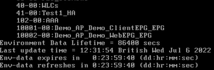
Delete that same SGT in ISE and push the change.
Again, the active C9800 is updated and sync’d to the standby:
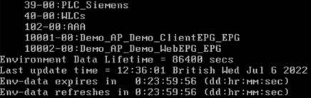
Add a new policy in ISE and assign an SGACL not already downloaded by the C9800. Add new policy from 29 to 11 using SGACL called AllowWeb.
As SGT 11 is being protected by the C9800, the newly added policy and SGACL are downloaded, and sync’d to the Standby:
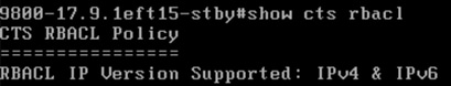
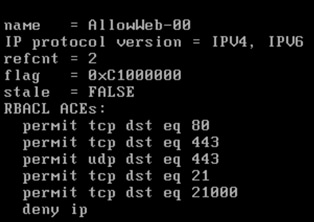
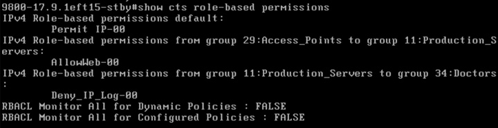
To test switch-over behaviour: A wireless client is authenticated (10.1.210.100) and assigned Doctors SGT 34. Traffic being sent from wireless client to wired (10.1.140.2) using central switching.
Before switch-over:
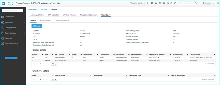
9800-17.9.1#redundancy force-switchover
System configuration has been modified. Save? [yes/no]: yes
Building configuration...
[OK]Proceed with switchover to standby RP? [confirm]
Manual Swact = enabled
[Connection to 10.1.200.30 closed by foreign host]
Was dropped from GUI access but could log in again very quickly.
Centrally switched client experienced a very small outage:
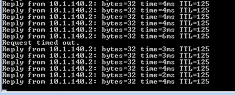
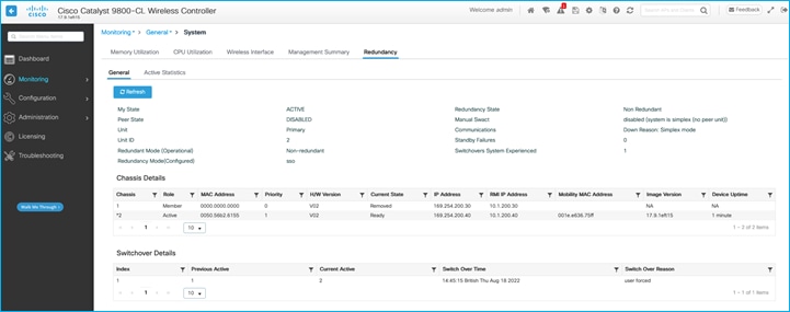
On the new active C9800 controller, captured the following output.
See that a new PAC has been downloaded, the management IP is available on the new active controller, and SXP is now terminated on the new active platform so IP:SGT mappings from SXP are shown:
9800-17.9.1#show redundancy
Redundant System Information :
------------------------------
Available system uptime = 6 weeks, 1 day, 4 hours, 8 minutes
Switchovers system experienced = 1
Standby failures = 0
Last switchover reason = user forced
Hardware Mode = Duplex
Configured Redundancy Mode = sso
Operating Redundancy Mode = sso
Maintenance Mode = Disabled
Communications = Up
Current Processor Information :
-------------------------------
Active Location = slot 2
Current Software state = ACTIVE
Uptime in current state = 6 minutes
Image Version = Cisco IOS Software [Cupertino], C9800-CL Software (C9800-CL-K9_IOSXE), Version 17.9.1eft15, RELEASE SOFTWARE (fc1)
Technical Support: http://www.cisco.com/techsupport
Copyright (c) 1986-2022 by Cisco Systems, Inc.
Compiled Fri 24-Jun-22 20:01 by mcpre
BOOT = bootflash:packages.conf,12;
CONFIG_FILE =
Configuration register = 0x2102
Recovery mode = Not Applicable
Fast Switchover = Enabled
Initial Garp = Enabled
Peer Processor Information :
----------------------------
Standby Location = slot 1
Current Software state = STANDBY HOT
Uptime in current state = 2 minutes
Image Version = Cisco IOS Software [Cupertino], C9800-CL Software (C9800-CL-K9_IOSXE), Version 17.9.1eft15, RELEASE SOFTWARE (fc1)
Technical Support: http://www.cisco.com/techsupport
Copyright (c) 1986-2022 by Cisco Systems, Inc.
Compiled Fri 24-Jun-22 20:01 by mcpre
BOOT = bootflash:packages.conf,12;
CONFIG_FILE =
Configuration register = 0x2102
9800-17.9.1#show cts pacs
AID: AF8B97E848CC486737DFC8124B7F00AD
PAC-Info:
PAC-type = Cisco Trustsec
AID: AF8B97E848CC486737DFC8124B7F00AD
I-ID: 9800-CL
A-ID-Info: Identity Services Engine
Credential Lifetime: 14:45:28 British Nov 16 2022
PAC-Opaque: 000200B00003000100040010AF8B97E848CC486737DFC8124B7F00AD000600940003010030E530662F9D5B3B8601E4CE0EF219B40000001362F529BE00093A80CF372B658E9FFDE1540B6AD39FC684DCB55BF26962FEF47528023372B48DAEE2F58430FE7279B66DE8227C9D4C9BC584CDB33C49661B4FF836F8A0CF28AA68B61B894FCF409A47441F5DCAC97EECC332BF6D53EDCC71A6D12662E4A79865ED2B1E917FE3E3D46A5D0B1194DC8329425EB595B2EF
Refresh timer is set for 12w4d
9800-17.9.1#show cts environment-data
CTS Environment Data
====================
Current state = COMPLETE
Last status = Successful
Service Info Table:
Local Device SGT:
SGT tag = 2-01:TrustSec_Devices
Server List Info:
Installed list: CTSServerList1-0001, 1 server(s):
Server: 10.1.101.30, port 1812, A-ID AF8B97E848CC486737DFC8124B7F00AD
Status = ALIVE
auto-test = FALSE, keywrap-enable = FALSE, idle-time = 60 mins, deadtime = 20 secs
Security Group Name Table:
0-00:Unknown
2-00:TrustSec_Devices
3-01:Network_Services
4-01:Employees
5-02:Contractors
6-01:Guests
7-01:Production_Users
8-01:Developers
9-02:Auditors
10-01:Point_of_Sale_Systems
11-10:Production_Servers
12-03:Development_Servers
13-00:Test_Servers
14-01:PCI_Servers
15-02:BYOD
16-00:Intranet
17-00:Extranet
18-02:HVAC
19-02:Lighting
20-02:Water_Control
21-00:Entertainment_Systems
22-01:CC_TV
23-02:Bldg_Acc_Ctrl
24-00:Intruder_Detection
25-02:Energy_Control
27-02:IP_Phones
28-09:Cameras
29-01:Access_Points
30-00:High_Trust_CT_Scanners
31-00:Low_Trust_CT_Scanners
32-01:Wireless_Clients
33-00:EFT_SGT1
34-39:Doctors
35-01:Storage
36-08:Scanners
37-00:Nurses
255-00:Quarantined_Systems
39-00:PLC_Siemens
40-00:WLCs
Environment Data Lifetime = 86400 secs
Last update time = 14:45:41 British Thu Aug 18 2022
Env-data expires in 0:23:57:46 (dd:hr:mm:sec)
Env-data refreshes in 0:23:57:46 (dd:hr:mm:sec)
Cache data applied = NONE
State Machine is running
Retry_timer (60 secs) is not running
9800-17.9.1#
9800-17.9.1#show cts role-based sgt-map all
Active IPv4-SGT Bindings Information
IP Address SGT Source
============================================
1.1.1.8 2 SXP
10.1.200.1 2 SXP
10.1.210.1 2 SXP
10.1.210.10 2 INTERNAL
10.1.210.100 34 LOCAL
10.1.211.1 2 SXP
10.1.211.10 2 INTERNAL
10.3.23.2 2 SXP
10.4.25.2 2 SXP
10.6.50.100 28 SXP
10.6.50.254 2 SXP
IP-SGT Active Bindings Summary
============================================
Total number of SXP bindings = 8
Total number of LOCAL bindings = 1
Total number of INTERNAL bindings = 2
Total number of active bindings = 11
Active IPv6-SGT Bindings Information
IP Address SGT Source
================================================================
9800-17.9.1#
9800-17.9.1#show cts rbacl
CTS RBACL Policy
================
RBACL IP Version Supported: IPv4 & IPv6
name = Deny_IP_Log-00
IP protocol version = IPV4, IPV6
refcnt = 2
flag = 0xC1000000
stale = FALSE
RBACL ACEs:
deny ip log
name = Deny IP-00
IP protocol version = IPV4, IPV6
refcnt = 2
flag = 0xC1000000
stale = FALSE
RBACL ACEs:
deny ip
name = Permit IP-00
IP protocol version = IPV4, IPV6
refcnt = 6
flag = 0xC1000000
stale = FALSE
RBACL ACEs:
permit ip
name = DenyIPlog-01
IP protocol version = IPV4, IPV6
refcnt = 2
flag = 0xC1000000
stale = FALSE
RBACL ACEs:
deny ip log
9800-17.9.1#show cts role-based permissions
IPv4 Role-based permissions default:
Permit IP-00
IPv4 Role-based permissions from group 15:BYOD to group 28:Cameras:
Permit IP-00
IPv4 Role-based permissions from group 31:Low_Trust_CT_Scanners to group 28:Cameras:
Permit IP-00
IPv4 Role-based permissions from group 33:EFT_SGT1 to group 28:Cameras:
Deny_IP_Log-00
IPv4 Role-based permissions from group 34:Doctors to group 28:Cameras:
Permit IP-00
IPv4 Role-based permissions from group 11:Production_Servers to group 34:Doctors:
Deny IP-00
IPv4 Role-based permissions from group 33:EFT_SGT1 to group 34:Doctors:
DenyIPlog-01
RBACL Monitor All for Dynamic Policies : FALSE
RBACL Monitor All for Configured Policies : FALSE
The conclusion is that HA operation works successfully in a GBP environment. Take note of the following DDTS entry for HA operation: CSCwc78021 9800: Standby controller crash @ fman_acl_remove_default_ace
This is fixed in release 17.10.1
Foreign - Anchor Operation with SGTs
Setup and SGT Assignment in Anchor Scenario
Foreign - Anchor is a commonly used design when customers want to segment the wireless traffic in a secure and easy way from multiple distributed locations (where the Foreign WLCs would reside) to a centralized one (where the Anchor would be placed), typically the DMZ of the Internet edge network. A typical use case would be for guest traffic to be tunneled directly to the DMZ to have a direct access to Internet, in one location that you can easily control, for example filtering or rate limiting. Same is true for IoT traffic that needs to be segmented and tunnel to a centralized location where the IoT servers reside.
This section describes how GBP works in a Foreign-Anchor deployment and will consider four scenarios: Dynamically assigning SGTs to wireless clients and propagating the SGT info from Anchor, East West and North to South policy enforcement at the Anchor.
To understand how policy works in a Foreign – Anchor scenario, there is a simple rule to keep in mind: anything related to client Layer 2 security happens at the foreign, anything related to Layer 3 security and IP happens at the Anchor.
For example, if the SSID is configured with 802.1x security, the Foreign is responsible to talk to ISE to authenticate the user, the Anchor is responsible to bridge the client traffic to the mapped VLAN and handle DHCP and any client traffic.
Before starting to configure the GBP settings, you need to configure the two WLCs to assume the role of Foreign and Anchor. Foreign is the C9800 that has APs connected to it, the Anchor will be the C9800 in the centralized location and usually doesn’t have any APs joined.
Here you can find a detailed step by step configuration guide on how to configure Foreign Anchor: https://www.cisco.com/c/en/us/support/docs/wireless/catalyst-9800-series-wireless-WLCs/213912-configure-mobility-anchor-on-catalyst-98.html
Let’s see the most important steps, starting with building the tunnel between the two C9800s.
On the C9800 that you want to configure as Foreign go to Configuration > Wireless > Mobility and set the Mobility Group name (Kernow in this case) and record the Mobility MAC as you will have to use it later.
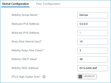
Do the same thing on the Anchor C9800 as shown in the picture below:
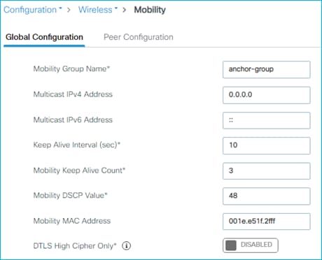
It’s a good practice to configure two different mobility group names on Foreign and Anchor, unless you have clients roaming between the two controller, which is usually not the case as the Anchor doesn’t have any APs connected; if it does, they are not in the same location as the APs joined to the Foreign, so roaming will not happen between the two networks.
Next, you need to set the other C9800 as peer. On the Foreign, click on the “Peer Configuration” tab and then click on the +add icon. In the popup window enter the information about the anchor C9800: the Mobility MAC previously recorded, the IP address of the Wireless Management interface and then type the mobility group name of the anchor.
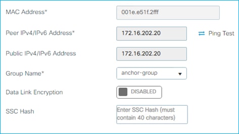
Data link encryption is optional and would be required to DTLS encrypt the client traffic between Foreign and Anchor. Repeat the same procedure on the Anchor entering the data related to the remote peer:
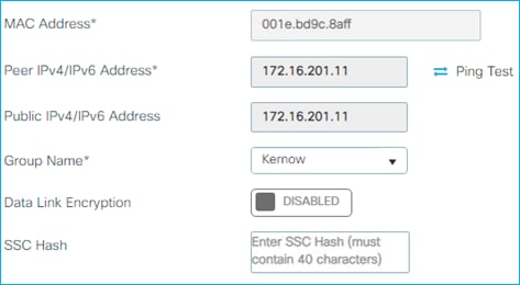
Once this is done, after few seconds, you will see that the CAPWAP tunnel comes up as you can see form the status in the picture below on Foreign:
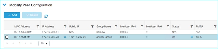
Next step is to configure an SSID to be anchored, so all the traffic from clients connected to that SSID will be automatically tunneled at the Foreign to the Anchor where it would enter the wired network. On the Foreign, no changes are made on the WLAN, you just need to change the associated policy profile. Go to Configuration > Tags & Profiles > Policy, select the Policy profile, Kernow-Guests-Policy in this case:
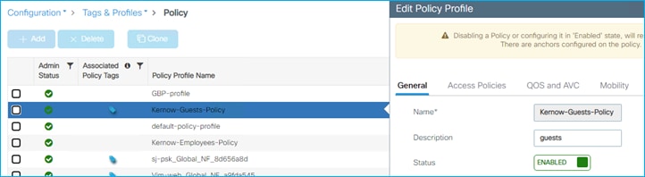
Then click on the Mobility tag and click the blue arrow to select the available Anchor IP:
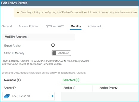
This will select the Anchor C9800 and assign the priority. You can change the priority if you have multiple Anchors and you want a Primary/Secondary/Tertiary:
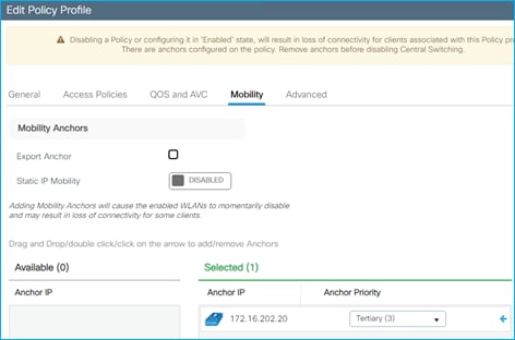
This is all you must do on the Foreign. On the Anchor, you need to create the WLAN and the policy profile as they are defined on the Foreign. Important: the name of the WLAN, the name of the policy profile need to match; also, the security settings under the WLAN and the DHCP settings in the policy profile, need to be identical.
Once you have created the WLAN and the Policy profile, you need to configure the C9800 as anchor for the selected SSID and hence policy profile. To do this, on the Anchor 9800, go to Configuration > Tags & Profiles > Policy, select the Policy profile, Kernow-Guests-Policy, same name and configuration as the one on the Foreign but the mobility configuration is different:
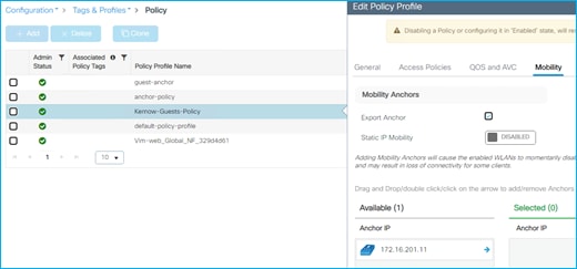
As you can see, in this case, you only must check the Export Anchor checkmark. Do not select the anchor IP as it was done on Foreign, as this is the C9800 that must terminate the traffic. It’s important to define the VLAN that the anchored clients will be bridged to, and you do this under the policy profile again:
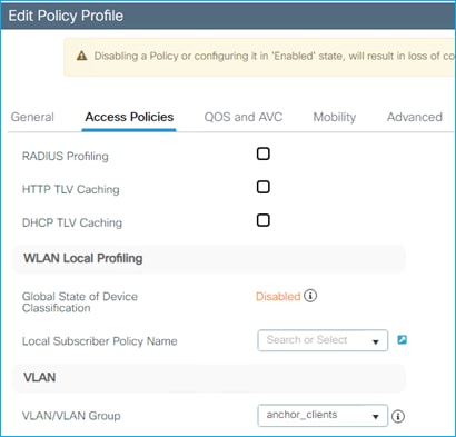
The vlan name anchor_clients is mapped to VLAN 211 in this Lab, but the important thing to remember is that this VLAN has nothing to do with the VLAN you have mapped on the same policy profile on the Foreign. As a matter of fact, the VLAN on the Foreign really doesn’t matter as the traffic is tunneled and not bridged locally.
Now, you are ready to configure the policy section, let’s consider three different scenarios.
Dynamic SGT assignment in Anchor Scenario.
As stated earlier, L2 client authentication and authorization happens on Foreign, so for dynamic SGT propagation, you don’t need to configure anything AAA related in the Anchor. When the client joins the 802.1x SSID, the Foreign acts as Network Access Server (NAS) and retrieves the SGT information from ISE.
The Foreign then forwards this information to the Anchor together with the WLAN and Profile name, so the Anchor knows how to treat this client. The Anchor will bridge the traffic in VLAN anchor_clients (211) and clients will be receiving an IP address from subnet 172.16.211.0/24 as you can see in the screen shot on Foreign going to Monitoring > Wireless > Clients:
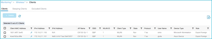
And on Anchor:
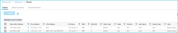
The only difference is the client role: in the Foreign it says Export Foreign and in Anchor is Export Anchor. If you click on client “giulia” (the Nurse), you will see under General > Security information that the SGT information is present on the Anchor (SGT is 0024 in hexadecimal, which is SGT = 36)
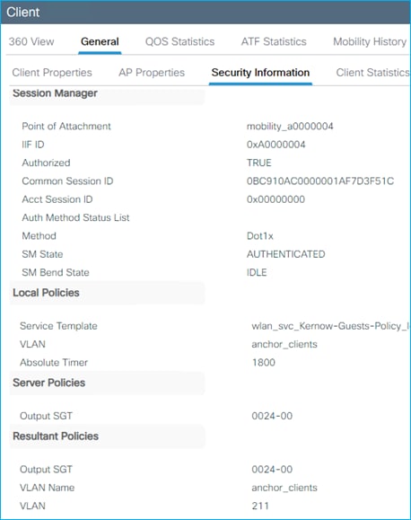
SGT propagation in Anchor scenario
SGT propagation works in the same way as for the standalone controller, the only thing you need to remember is that in this case, you must configure either inline tagging or SXP at the Anchor and not at the Foreign as it’s the Anchor responsible for forwarding traffic to the wired network.
The configuration is the same as seen previously in this document. For inline tagging, we need to configure “cts manual” on the uplink interface. In this case, since it’s a C9800-CL, Gigabit Ethernet 2 is the uplink port to the wired network. As soon as you configure the inline tagging as per picture below:
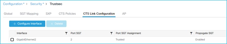
The C9800 starts adding the CMD header in the frames it sends out from wireless client to the wired network. Here is a capture of ping traffic from wireless client to 8.8.8.8. See the Cisco Meta Data (CMD) section the and the SGT info:
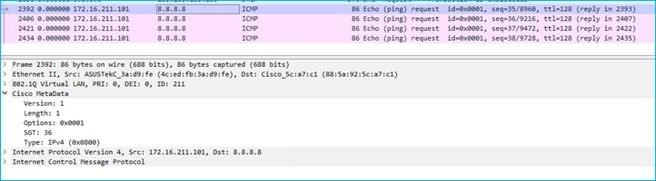
The other way to propagate the wireless client SGT and IP mapping would be to configure an SXP session to a remote switch. This works on the Anchor the same way it was configured on standalone controller we saw previously.
Policy enforcement for East West traffic in Anchor Scenario.
If you want to enforce a GBP, then you need to configure the Anchor controller to talk to ISE and download the environmental data and the policies associated to the anchor clients. The configuration on ISE is the same as seen previously for the standalone controller scenario. Similarly, the AAA configuration on the C9800 Anchor is the same as for the standalone controller, reported here for clarity:
!
aaa authentication dot1x ise-auth group my-ise
aaa authorization network default local
aaa authorization network ise-authz group my-ise
!
aaa server radius dynamic-author
client 172.16.3.4 server-key XXXX
!
!
radius server ise
address ipv4 172.16.3.4 auth-port 1812 acct-port 1813
timeout 4
retransmit 3
pac key XXX
!
!
aaa group server radius my-ise
server name ise
ip radius source-interface Vlan202
!
aaa new-model
aaa session-id common
!
radius server ise
address ipv4 172.16.3.4 auth-port 1812 acct-port 1813
timeout 4
retransmit 3
pac key Vimlab123
To enable GBP, you need to configure the TrustSec parameters on C9800 Anchor under Configuration > Security > Trustsec > Global:
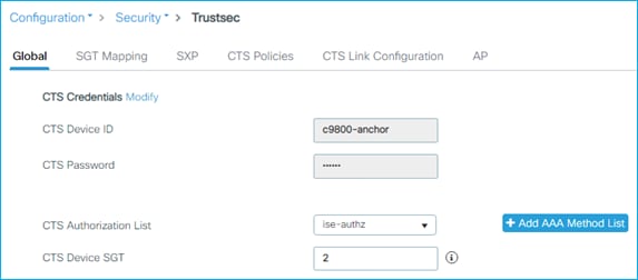
This will trigger the additional two commands in the configurations:
cts authorization list ise-authz
cts sgt 2
Once this is done, you can test policy enforcement on the same SSID and policy profile between clients with different SGTs. In this case two clients are connected:
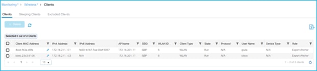
Client with IP 172.16.211.103 is associated to group Doctors and got SGT = 34, the client with IP 172.16.211.100 got assigned SGT = 36. The moment the clients connect, C9800 Anchor downloads the policy from ISE, and you can see it on the box for example here:
c9800-anchor#show cts role-based permissions
IPv4 Role-based permissions default:
Permit IP-00
IPv4 Role-based permissions from group 6:Guests to group 34:Doctors:
Deny IP-00
IPv4 Role-based permissions from group 36:Nurses to group 34:Doctors:
Deny IP-00
Before starting the traffic, you see that the counters related to those SGTs are all zeros.
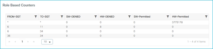
For policy to be enforced on East West traffic (wireless to wireless) you need to enable SGACL Enforcement under CTS Policy on the Policy Profile:
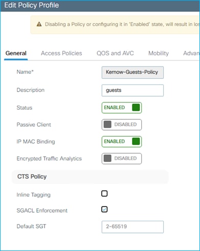
This only needs to be done on the Policy Profile on Anchor, not on Foreign.
Then you start a ping from a doctor device (SGT = 36) to a nurse device (SGT = 34) and the ping fails and the counters are increased, so enforcement is happening:
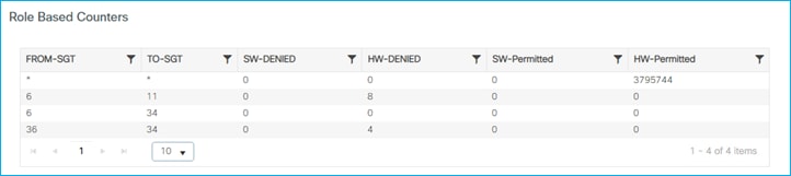
Policy enforcement for North South traffic in Anchor Scenario.
As described in earlier section, C9800 policy enforcement for traffic from wired to wireless (North-South) happens at the controller itself; this is different from AireOS where the enforcement was done on the AP. The Anchor scenario is not different, and the GBP for traffic coming from the wired network and destined to one of the registered clients, is blocked at the Anchor which is the first point of ingress into the wireless network. Let’s consider a use case where you want to block contractor wireless users (SGT = 5) to communicate with the production server (SGT = 11 and IP address 172.16.3.4). You set a policy in ISE to deny such traffic:
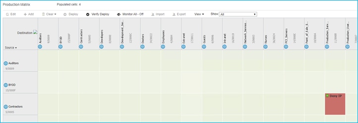
As soon as a wireless client from the Contractor group joins, it gets assigned SGT 5 and the related SGACL policy is downloaded to the C9800. You can get the SGT details from the Monitor > Client page:
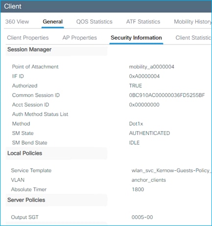
To block the traffic the C9800 needs to know the IP:SGT mapping for the production server (172.16.3.4); this can be learnt via inline tagging or via SXP. Let’s consider SXP for this example. As done in the standalone case, you setup a SXP connection with the switch where the Servers are connected. Go to Configuration > Security > TrustSec > SXP and setup the SXP peer and the C9800 Anchor as a Listener as it has to receive the mapping:
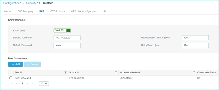
In the lab the switch is the default gateway, but in general the SXP peer could be multiple IP hops away.
Once the session is on, the C9800 will start learning the IP:SGT mappings as shown here:
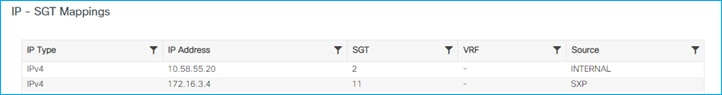
As you notice the source is SXP.
Before sending any traffic, the role-based counters are all zero:
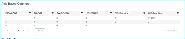
Now start a ping from the server or from the client, you will see ping fail and the counters increasing.
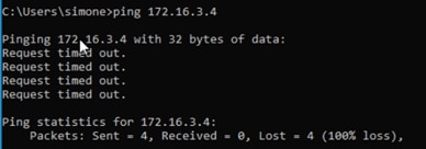
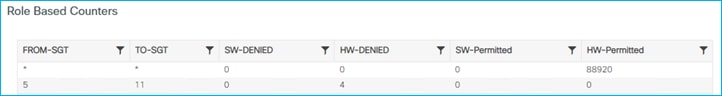
This confirms that the C9800 is blocking the traffic.
SGACL Logging on C9800 controller
SGACL logging occurs if the ‘log’ keyword is suffixed to any of the SGACE’s (entries) within an SGACL.
There’s an existing policy in ISE downloaded to the C9800:
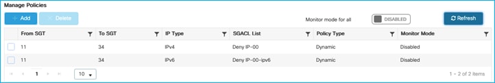
Change the assigned SGACL in ISE (Deny IP) to one with ‘Deny IP log’ and push the change to the C9800.
The C9800 is updated and the SGACL List is accurate:
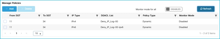
Navigate to Configuration > Security > AAA to see the downloaded SGACLs:
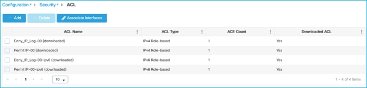
Click on the Deny_IP_Log entry to see the details, Log is Enabled:
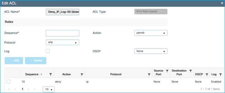
Traffic is actually denied:
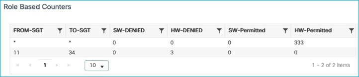
Navigate to Troubleshooting > Logs and entries such as the following will be displayed in the Syslog:
Jul 5 15:03:09.837: %FMANFP-6-IPACCESSLOGSGDP: Chassis 1 F0/0: fman_fp_image: ingress_interface='VLAN-CPPIF-0210' sgacl_name='Deny_IP_Log-00' action='Deny' protocol='icmp' src-ip='10.1.140.2' dest-ip='10.1.210.100' type='0' code='0' sgt='11' dgt='34' logging_interval_hits='1'
And the following to indicate a number of hits (logging interval):
Jul 5 15:11:22.340: %FMANFP-6-IPACCESSLOGSGDP: Chassis 1 F0/0: fman_fp_image: ingress_interface='VLAN-CPPIF-0210' sgacl_name='Deny_IP_Log-00' action='Deny' protocol='icmp' src-ip='10.1.140.2' dest-ip='10.1.210.100' type='0' code='0' sgt='11' dgt='34' logging_interval_hits='61'
The conclusion is that SGACL logging works well on the C9800.
SGACL Logging on Flex AP (Not Supported)
As in the case of testing SGACL logging on the C9800, setup wired to wireless enforcement on a Flex AP:
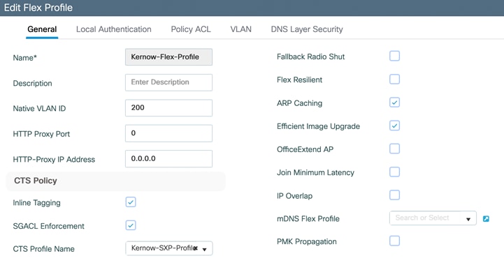
Tested enforcing from SGT 33 (wired) to SGT 34 (Wireless), and used ‘deny ip log’ as an SGACL to try to generate syslog messages of any hits:
AP0845.D132.75F8#show cts role-based permissions
IPv4 role-based permissions:
SGT DGT ACL
11 34 Deny_IP
23 34 AllowDHCPDNS
33 34 DenyIPlog
Can see enforcement hits:
AP0845.D132.75F8#show cts role-based counters from 33 to 34
IPv4 ACL: DenyIPlog
Packets Allowed : 0
Packets Denied : 484
IPv6 ACL: DenyIPlog
Packets Allowed : 0
Packets Denied : 0
But no syslog messages are generated.
Syslog messages are not supported for enforcement on Flex AP’s.
Configured NetFlow as follows, note the SGT match commands in red. Platforms like Secure Network Analytics (Stealthwatch) can consume this context.
Note: Cisco Catalyst Center does not consume SGT context within NetFlow records. Cisco Catalyst Center along with other platforms including Secure Network Analytics (Stealthwatch) can utilize ISE pxGrid to learn of the SGT information related to traffic flows.
flow record NetFlow-in
match datalink mac source address input
match datalink mac destination address input
match ipv4 tos
match ipv4 ttl
match ipv4 protocol
match ipv4 source address
match ipv4 destination address
match transport source-port
match transport destination-port
match interface input
match flow direction
match flow cts source group-tag
match flow cts destination group-tag
collect counter bytes long
collect counter packets long
collect timestamp absolute first
collect timestamp absolute last
!
flow record NetFlow-out
match ipv4 tos
match ipv4 ttl
match ipv4 protocol
match ipv4 source address
match ipv4 destination address
match transport source-port
match transport destination-port
match flow direction
match flow cts source group-tag
match flow cts destination group-tag
collect counter bytes long
collect counter packets long
collect timestamp absolute first
collect timestamp absolute last
!
flow exporter NetFlow-Exp
destination 10.1.110.3
source GigabitEthernet1
transport udp 2055
!
flow monitor NetFlow-mon-in
exporter NetFlow-Exp
cache timeout active 60
record NetFlow-in
!
flow monitor NetFlow-mon-out
exporter NetFlow-Exp
cache timeout active 60
record NetFlow-out
Attach the flow monitors to the C9800 controller uplink G2:
interface GigabitEthernet2
switchport trunk allowed vlan 200,210,211
switchport mode trunk
switchport nonegotiate
ip flow monitor NetFlow-mon-in input
ip flow monitor NetFlow-mon-out output
negotiation auto
no mop enabled
no mop sysid
end
Both source and destination SGTs can be seen to be inserted into the NetFlow packets for a flow between wireless 10.1.210.100 with Doctors SGT 34 and wired 10.1.140.2 with Production_Servers SGT 11:
9800-17.9.1#show flow monitor NetFlow-mon-out cache
IPV4 SOURCE ADDRESS: 10.1.210.100
IPV4 DESTINATION ADDRESS: 10.1.140.2
TRNS SOURCE PORT: 0
TRNS DESTINATION PORT: 0
FLOW DIRECTION: Output
FLOW CTS SOURCE GROUP TAG: 34
FLOW CTS DESTINATION GROUP TAG: 11
IP TOS: 0x00
IP PROTOCOL: 1
IP TTL: 128
counter bytes long: 2580
counter packets long: 43
timestamp abs first: 16:07:19.902
timestamp abs last: 16:08:01.921
The C9800 Dashboard is the main page to investigate the state of the controller and associated AP’s including WLANs, Access Points and Clients:
However, to discover the general state of GBP within the controller, navigate to Monitoring > General > TrustSec. This shows whether the PAC and Environment-data has been downloaded, the server list and the SGTs within the Environment-data, all the IP-SGT mappings and the SGACL (Role-Based) Counters:
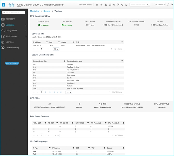
While good TrustSec information can be gleaned from the Monitoring screen above, the actual policy information is missing from that location. To investigate policies downloaded from ISE, navigate to Configuration > Security > TrustSec > CTS Policies:
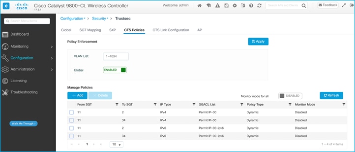
Remember, the only policies that will be downloaded from ISE, and therefore present in this table, will be for policies with a destination SGT that the C9800 controller knows about. In the Monitoring > General > TrustSec screen you can see this C9800 knows about IP:SGT mappings for SGT 2 and 34, therefore only policies destined towards those SGTs are downloaded.
Any SGT dynamically assigned to a client will show up in the IP-SGT mappings table within the TrustSec Monitoring screen above but can also be seen in the client information. Navigate to the Dashboard, then click on the active client number, or navigate using Monitoring > Wireless > Clients:
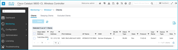
To check on the SGT assigned, click the client entry, then the General tab, then ‘Security Information’, scroll down to Server Policies > Output SGT, or Resultant Policies > Output SGT; (the SGT is shown in Hex in this screen):
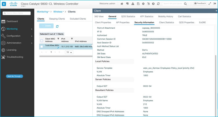
Note: The SGT is shown in the form 22-54 where 22 is the SGT in Hex i.e., 34 Dec, and the 54 is a version number used to help keep the SGT and related data synchronized with ISE.
The IP and the assigned SGT can be gleaned from the client information as seen above, and we have also seen the IP:SGT mapping shown in the Monitoring > General > TrustSec screen. The same information can also be seen at Configuration > Security > TrustSec > SGT Mapping (where static mappings can also be added if required):
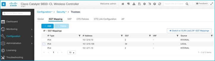
The C9800 controller can be configured to propagate SGTs via inline tagging or via Security Group Tag Exchange Protocol (SXP). There is no GUI screen which shows the state of inline tagging, but once enabled, the following CLI could be used:
9800-17.9.1#show cts interface
Global Dot1x feature is Disabled
Interface GigabitEthernet2:
CTS is enabled, mode: MANUAL
IFC state: OPEN
Interface Active for 4d17h
Authentication Status: NOT APPLICABLE
Peer identity: "unknown"
Peer's advertised capabilities: ""
Authorization Status: SUCCEEDED
Peer SGT: 2:TrustSec_Devices
Peer SGT assignment: Trusted
SAP Status: NOT APPLICABLE
Propagate SGT: Enabled
Cache Info:
Expiration : N/A
Cache applied to link : NONE
Statistics:
authc success: 0
authc reject: 0
authc failure: 0
authc no response: 0
authc logoff: 0
sap success: 0
sap fail: 0
authz success: 0
authz fail: 0
port auth fail: 0
L3 IPM: disabled.
CTS sgt-caching Ingress : Disabled
CTS sgt-caching Egress : Disabled
The state of an SXP connection on the C9800 can be seen within Configuration > Security > TrustSec > SXP where it shows the Connection Status for each added connection:

SXP state can also be checked using CLI on the C9800:
9800-17.9.1#show cts sxp connections
SXP : Enabled
Highest Version Supported: 5
Default Password : Set
Default Key-Chain: Not Set
Default Key-Chain Name: Not Applicable
Default Source IP: Not Set
Connection retry open period: 120 secs
Reconcile period: 120 secs
Retry open timer is not running
Peer-Sequence traverse limit for export: Not Set
Peer-Sequence traverse limit for import: Not Set
----------------------------------------------
Peer IP : 10.1.200.1
Source IP : 10.1.200.10
Conn status : On
Conn version : 5
Conn capability : IPv4-IPv6-Subnet
Conn hold time : 120 seconds
Local mode : SXP Listener
Connection inst# : 1
TCP conn fd : 1
TCP conn password: default SXP password
Hold timer is running
Duration since last state change: 0:00:25:07 (dd:hr:mm:sec)
Total num of SXP Connections = 1
9800-17.9.1#show cts sxp sgt-map
SXP Node ID(generated):0x0A01D30A(10.1.211.10)
IP-SGT Mappings as follows:
IPv4,SGT: <1.1.1.8 , 2:TrustSec_Devices>
source : SXP;
Peer IP : 10.1.200.1;
Ins Num : 1;
Status : Active;
Seq Num : 1
Peer Seq: 01010108,
IPv4,SGT: <10.1.200.1 , 2:TrustSec_Devices>
source : SXP;
Peer IP : 10.1.200.1;
Ins Num : 1;
Status : Active;
Seq Num : 3
Peer Seq: 01010108,
Total number of IP-SGT Mappings: 2
The following command is useful to determine the details of enforcement, inline tagging and default-SGT for the various profiles:
9800-17.9.1#show wireless cts summary
Local Mode CTS Configuration
Policy Profile Name SGACL Enforcement Inline-Tagging Default-Sgt
----------------------------------------------------------------------------------------
Kernow-Flex_Policy ENABLED DISABLED 2
default-policy-profile DISABLED DISABLED 0
Kernow-Employees-Policy ENABLED DISABLED 0
Flex Mode CTS Configuration
Flex Profile Name SGACL Enforcement Inline-Tagging
-----------------------------------------------------------------------
Kernow-Flex-Profile ENABLED ENABLED
default-flex-profile DISABLED DISABLED
If the mode is Flex, then the SGTs and whether policies are present on an AP can be seen via the C9800 GUI by navigating to Monitoring > Wireless > AP Statistics > Select AP > TrustSec (see ‘Policy Pushed to AP’ column):
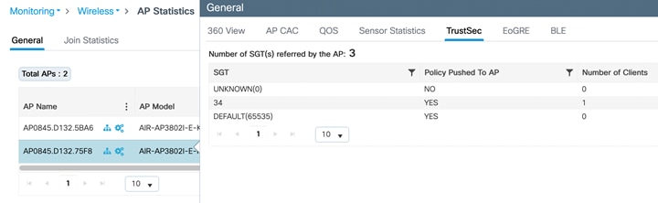
The equivalent via CLI is:
9800-17.9.1#show cts ap sgt-info AP0845.D132.75F8
Number of SGTs referred by the AP...............: 3
SGT PolicyPushedToAP No.of Clients
------------------------------------------------------------
UNKNOWN(0) NO 0
34 YES 1
DEFAULT(65535) YES 0
CLI commands can be used on a Flex AP as follows:
AP0845.D132.75F8#show cts sxp connections
SXP : Enabled
Highest Version Supported: 4
Default Password : Set
SXP Timers:
Connection retry open period:120
Reconcile period:120
Keepalive period:65535
Speaker minimum hold-time:120
Listener minimum hold-time:90
Listener maximum hold-time:120
SXP Connection Info:
peer #0: 10.1.201.1:64999
1 connection(s) active
connection status: successful
hold timer is armed
peer has speaker role
1 configured peer(s)
AP0845.D132.75F8#show cts sxp sgt-map
IPv4 Binding(s):
Binding #0: 1.1.1.6/32 = 2
Binding #1: 10.1.201.1/32 = 2
Binding #2: 10.1.202.1/32 = 2
Binding #3: 10.3.25.2/32 = 2
Binding #4: 10.4.21.2/32 = 2
Binding #5: 10.6.5.111/32 = 34
Binding #6: 10.6.5.254/32 = 2
IPv6 Binding(s):
AP0845.D132.75F8#show cts role-based sgt-map all
Active IPv4-SGT Bindings Information
IP SGT SOURCE
10.1.202.10 34 LOCAL
IP-SGT Active Bindings Summary
============================================
Total number of LOCAL bindings = 1
Total number of active bindings = 1
Active IPv6-SGT Bindings Information
IP SGT SOURCE
fe80::90de:54f8:a770:5a79 34 LOCAL
IP-SGT Active Bindings Summary
============================================
Total number of LOCAL bindings = 1
Total number of active bindings = 1
AP0845.D132.75F8#show cts role-based permissions
IPv4 role-based permissions:
SGT DGT ACL
11 34 Permit_IP
65535 65535 Permit_IP
IPv6 role-based permissions:
SGT DGT ACL
11 34 Permit_IP
65535 65535 Permit_IP
AP0845.D132.75F8#show cts role-based counters from 11 to 34
IPv4 ACL: Permit_IP
Packets Allowed : 0
Packets Denied : 11
IPv6 ACL: Permit_IP
Packets Allowed : 0
Packets Denied : 0
AP0845.D132.75F8#show cts access-lists
IPv4 role-based ACL:
Permit_IP
rule 0: allow true
IPv6 role-based ACL:
Permit_IP
rule 0: allow true
There are various CTS debugs that can be set on a C9800 controller. The list below shows the options, choose the relevant debug to match the requirement:
9800-17.9.1#debug cts ?
aaa CTS AAA
all all CTS messages
authentication CTS authentication
authorization CTS authorization
cache CTS Cache
coa CTS Change of Authorization
critical-authentication CTS Critical-Authentication
dp CTS Datapath (DP)
environment-data CTS environment data operations
error CTS error and warning messages
ha CTS HA
ifc CTS Interface CONTROLLER (IFC)
layer3-trustsec CTS Layer3 TrustSec/Policy
odm CTS Operational data modeling debugs
policy-server CTS policy server debugs
provisioning CTS PAC-provisioning
rcl-server CTS RCL
relay CTS Relay
sap CTS Security Association Protocol (SAP)
server-list CTS server list operations
sgacl-db CTS SGACL database debugs
states CTS state change debugs
sxp CTS SXP
<cr> <cr>
Similarly, on a Flex AP, here is the debug list:
AP0845.D132.75F8#debug cts ?
enforcement Enable CTS packet level enforcement debugging
parser Enable CTS ACL parser debugging
sxp Enable CTS SXP debugging
| Function\Deployment |
Local mode |
FlexConnect |
SDA |
Guest Anchor |
| Dynamic SGT assignment |
C9800 |
C9800 and pushed to AP |
C9800 and pushed to AP |
Foreign C9800 and info pushed to Anchor |
| SGT Propagation using SXP and/or inline tagging (CMD) |
C9800 |
AP |
Fabric Edge |
Anchor C9800 |
| CTS Provisioning and ISE enrollment |
C9800 |
C9800 |
C9800 and Fabric Edge |
Foreign and Anchor C9800 |
| Change of Authorization (CoA) for client/device SGT |
C9800 |
C9800 and pushed to AP |
Foreign C9800 and info pushed to Anchor |
|
| East-West policy enforcement (wireless to wireless) |
C9800 (client destination Policy Profile) |
AP (client destination AP) |
Fabric Edge |
Anchor C9800 (client destination Policy Profile) |
| North-South policy enforcement (wired to wireless) |
C9800 |
AP |
Fabric Edge |
Anchor C9800 |
| South-North policy enforcement (wireless to wired) |
Upstream switch |
Upstream switch |
Destination Fabric Edge |
Upstream switch |
Group-Based Policy works very well on the C9800 controller and associated AP’s along with IOS-XE software version 17.9.1. Note the following comments and caveats:
Static IP:SGT sent via SXP. When adding a static IP:SGT on the C9800 controller, it gets propagated off-platform via SXP in this use-case. This is not a very useful capability; there’s no added context from a C9800 point of view. If the static mapping is required on the destination platform, then why not just add a static mapping there instead or propagate it there from another source like ISE for example. This is a similar capability that was offered by the Nexus5k; it’s just not very useful.
The C9800 controller does not support S-N (wireless to wired) enforcement on-platform at all. If enforcement is required in that direction, then the C9800 can propagate the wireless assigned SGTs to Northbound platforms via inline tagging or SXP.
When propagating IP:SGT mappings via CMD from or to the C9800 controller, the inline tagging setting on the Policy Profile is not used, the SGT is processed if inline tagging is set on the uplink interface. The use of the inline tagging setting on the policy profile will be introduced in a future release.
Inline tagging and SGACL enforcement settings on the Policy Profile are irrelevant in flex mode, it’s the settings on the Flex Profile which are used to determine if inline tagging and SGACL enforcement are enabled or not on the Flex AP.
SGACL logging is not supported from Flex AP.
Monitor Mode is not supported on Flex AP.
There are these DDTS entries to consider (not related to any particular use-cases within this guide):
CSCwb11073 AP with LSC support functionality is not complete and needs end-to-end work to be completed.
CSCwa18221 CTS is not supported under RLAN policy in eWLC.
CSCwa65584 C9800 controller does not accept Catalyst APs C91xx series as TrustSec capable platform.
This is fixed and supported from 17.9.1.
The following DDTS entries are related to use-cases in this document and are mentioned in their relevant sections:
This document shows use-cases where CoA messages are successful. Problems in CoA occur in certain circumstances when policies are updated multiple times with CoA instigated each time. The policies are updated on the C9800 ok but not downloaded to the AP. Fixed in release 17.9.2: CSCwc15911 CoA changes are not reflecting in Flex mode APs for TrustSec.
A statically assigned IP:SGT mapping for a wireless client is not propagated via CMD across the uplink. The SGT must be dynamically assigned from ISE for this propagation to occur. This would be a beneficial addition: CSCwd06879 C9800 wireless static IP to SGT mapping not inline tagged over uplink.
If VLAN:SGT classification is meant for statically classifying wireless clients (traffic coming in from the South-bound/wireless direction), then it does not work due to the GUI producing an error in provisioning: CSCwd06900 C9800 wireless static VLAN to SGT mapping GUI provisioning generates error.
It has been decided to temporarily hide the option to ‘Switch to VLAN List/L3IF-SGT Mappings’ under Configuration > Security > TrustSec > SGT Mapping in ongoing releases. If either of the two features are required in the future, then the functionality can be investigated and re-introduced: CSCwd14077 C9800: Hide the option to switch to VLAN List and L3IF to SGT Mappings in SGT Mapping screen.
L3IF operation. This function is used when a L3 link is connected to a ‘partner’ and L3 IP prefixes learned and an SGT assigned. The GUI does actually create an SGT under the VLAN and create a Subnet:SGT which does enforce. However, that isn’t really the intention of the L3IF function. If a Subnet:SGT mapping is required then why not just use the static Subnet:SGT function?
L3IF:SGT mapping is for the network device to learn of routing prefixes and as the C9800 is largely a L2 platform the full function cannot currently be realised.
It has been decided to temporarily hide the option to ‘Switch to VLAN List/L3IF-SGT Mappings’ under Configuration > Security > TrustSec > SGT Mapping in ongoing releases. If either of the two features are required in the future, then the functionality can be investigated and re-introduced: CSCwd14077 C9800: Hide the option to switch to VLAN List and L3IF to SGT Mappings in SGT Mapping screen.
Setting ‘Monitor Mode for all’ results in the generation of ‘Error in Configuring’. CSCwd14088 C9800: The option to set CTS Policy Monitor mode for all generates an error.
Monitor Mode on the C9800 works ok but the counters to show traffic hits are only shown in the CLI, not in the webui in release 17.9.1. Monitor Mode counters supported in the webui from 17.11: CSCwc96257 WebUI: SGACL counters is not getting shown for Monitor mode in webui.
Crashes are occasionally experienced on the standby controller in HA mode. Fixed in 17.10.1: CSCwc78021 9800: Standby controller crash @ fman_acl_remove_default_ace
In the past, CTS policies have been seen to remain even after removing enforcement. This is fixed and supported from 17.9.1: CSCwb52864 HCA: 9800L-HA policies were intact even after removing the enforcement from the wireless profile.
AAA Authentication, Authorization and Accounting
ACL Access Control List
AD Active Directory (Microsoft)
API Application Programming Interface
ASR Aggregation Services Router (Cisco)
CDP Cisco Discovery Protocol
CLI Command Line Interface
CMD Cisco Meta Data (field in L2 frame)
CoA Change of Authorization (RADIUS)
CTS Cisco Trusted Security
dB Database
DC Data Center
DHCP Dynamic Host Configuration Protocol
DGT Destination Group Tag
(Cisco) DNA (Cisco) Digital Network Architecture
(Cisco) DNAC (Cisco) Digital Network Architecture Center
DNS Domain Name System
eWLC C9800 controller
FIB Forwarding Information Base
GBP Group-Based Policy
FQDN Fully Qualified Domain Name
HTTP HyperText Transfer Protocol
IBNS Identity-Based Networking Services
IOS Internetwork Operating System (Cisco)
IP Internet Protocol
IPDT IP Device Tracking
ISE Identity Services Engine (Cisco)
ISR Integrated Services Router (Cisco)
L2 Layer 2
L3 Layer 3
LAN Local Area Network
MAB MAC authentication bypass
MAC Media Access Control (Address)
PAC Protected Access Credential
PAN Policy Administration Node (ISE)
PSN Policy Services Node (ISE)
pxGrid Platform Exchange Grid (Cisco)
RADIUS Remote Authentication Dial-In User Service
SDA Software Defined Access (Cisco)
SD-Access Software Defined Access (Cisco)
SGACL Security Group Access Control List
SGT Security Group Tag
SNMP Simple Network Management Protocol
SSH Secure Shell
SXP Security Group Tag Exchange Protocol
SXPSN Security Group Tag Exchange Policy Services Node (ISE)
SYSLOG System Log
TCP Transmission Control Protocol
UDP User Datagram Protocol
VLAN Virtual Local Area Network
VN Virtual Network
VPN Virtual Private Network
VRF Virtual routing and forwarding
VXLAN Virtual Extensible Local Area Network
WAN Wide Area Network
WLAN Wireless Local Area Network
Controller Wireless Local Area Network controller