VersaStack with Cisco ACI and IBM FlashSystem 9100 NVMe-accelerated Storage
Available Languages
Bias-Free Language
The documentation set for this product strives to use bias-free language. For the purposes of this documentation set, bias-free is defined as language that does not imply discrimination based on age, disability, gender, racial identity, ethnic identity, sexual orientation, socioeconomic status, and intersectionality. Exceptions may be present in the documentation due to language that is hardcoded in the user interfaces of the product software, language used based on RFP documentation, or language that is used by a referenced third-party product. Learn more about how Cisco is using Inclusive Language.
- US/Canada 800-553-2447
- Worldwide Support Phone Numbers
- All Tools
 Feedback
 Feedback

VersaStack with Cisco ACI and IBM FlashSystem 9100 NVMe-accelerated Storage
Deployment Guide for VersaStack with Cisco ACI, IBM FlashSystem 9100 with VMware vSphere 6.7 Update3
Published: February 5, 2020

About the Cisco Validated Design Program
The Cisco Validated Design (CVD) program consists of systems and solutions designed, tested, and documented to facilitate faster, more reliable, and more predictable customer deployments. For more information, go to:
http://www.cisco.com/go/designzone.
ALL DESIGNS, SPECIFICATIONS, STATEMENTS, INFORMATION, AND RECOMMENDATIONS (COLLECTIVELY, "DESIGNS") IN THIS MANUAL ARE PRESENTED "AS IS," WITH ALL FAULTS. CISCO AND ITS SUPPLIERS DISCLAIM ALL WARRANTIES, INCLUDING, WITHOUT LIMITATION, THE WARRANTY OF MERCHANTABILITY, FITNESS FOR A PARTICULAR PURPOSE AND NONINFRINGEMENT OR ARISING FROM A COURSE OF DEALING, USAGE, OR TRADE PRACTICE. IN NO EVENT SHALL CISCO OR ITS SUPPLIERS BE LIABLE FOR ANY INDIRECT, SPECIAL, CONSEQUENTIAL, OR INCIDENTAL DAMAGES, INCLUDING, WITHOUT LIMITATION, LOST PROFITS OR LOSS OR DAMAGE TO DATA ARISING OUT OF THE USE OR INABILITY TO USE THE DESIGNS, EVEN IF CISCO OR ITS SUPPLIERS HAVE BEEN ADVISED OF THE POSSIBILITY OF SUCH DAMAGES.
THE DESIGNS ARE SUBJECT TO CHANGE WITHOUT NOTICE. USERS ARE SOLELY RESPONSIBLE FOR THEIR APPLICATION OF THE DESIGNS. THE DESIGNS DO NOT CONSTITUTE THE TECHNICAL OR OTHER PROFESSIONAL ADVICE OF CISCO, ITS SUPPLIERS OR PARTNERS. USERS SHOULD CONSULT THEIR OWN TECHNICAL ADVISORS BEFORE IMPLEMENTING THE DESIGNS. RESULTS MAY VARY DEPENDING ON FACTORS NOT TESTED BY CISCO.
CCDE, CCENT, Cisco Eos, Cisco Lumin, Cisco Nexus, Cisco StadiumVision, Cisco TelePresence, Cisco WebEx, the Cisco logo, DCE, and Welcome to the Human Network are trademarks; Changing the Way We Work, Live, Play, and Learn and Cisco Store are service marks; and Access Registrar, Aironet, AsyncOS, Bringing the Meeting To You, Catalyst, CCDA, CCDP, CCIE, CCIP, CCNA, CCNP, CCSP, CCVP, Cisco, the Cisco Certified Internetwork Expert logo, Cisco IOS, Cisco Press, Cisco Systems, Cisco Systems Capital, the Cisco Systems logo, Cisco Unified Computing System (Cisco UCS), Cisco UCS B-Series Blade Servers, Cisco UCS C-Series Rack Servers, Cisco UCS S-Series Storage Servers, Cisco UCS Manager, Cisco UCS Management Software, Cisco Unified Fabric, Cisco Application Centric Infrastructure, Cisco Nexus 9000 Series, Cisco Nexus 7000 Series. Cisco Prime Data Center Network Manager, Cisco NX-OS Software, Cisco MDS Series, Cisco Unity, Collaboration Without Limitation, EtherFast, EtherSwitch, Event Center, Fast Step, Follow Me Browsing, FormShare, GigaDrive, HomeLink, Internet Quotient, IOS, iPhone, iQuick Study, LightStream, Linksys, MediaTone, MeetingPlace, MeetingPlace Chime Sound, MGX, Networkers, Networking Academy, Network Registrar, PCNow, PIX, PowerPanels, ProConnect, ScriptShare, SenderBase, SMARTnet, Spectrum Expert, StackWise, The Fastest Way to Increase Your Internet Quotient, TransPath, WebEx, and the WebEx logo are registered trademarks of Cisco Systems, Inc. and/or its affiliates in the United States and certain other countries.
All other trademarks mentioned in this document or website are the property of their respective owners. The use of the word partner does not imply a partnership relationship between Cisco and any other company. (0809R)
© 2020 Cisco Systems, Inc. All rights reserved.
Table of Contents
Cisco UCS Compute connectivity
IBM FS9100 Connectivity to Nexus Switches
Cisco Application Policy Infrastructure Controller (APIC) - Verification
Initial ACI Fabric Setup - Verification
Setting Up Out-of-Band Management IP Addresses for New Leaf Switches
Verifying Time Zone and NTP Server
Verifying BGP Route Reflectors
Verifying Fabric Wide Enforce Subnet Check for IP & MAC Learning
Create LLDP Interface Policies
Create BPDU Filter/Guard Policies
Create Virtual Port Channels (vPCs)
vPC – Cisco UCS Fabric Interconnects
Configure Breakout Ports for IBM FS9100 iSCSI Connectivity
Configure Individual Ports for FS9100 iSCSI Access
ACI Fabric Deployment – Layer 3 Routed Connectivity to Outside Networks
Create VLAN Pool for External Routed Domain
Configure Domain Type for External Routed Domain
Create Attachable Access Entity Profile for External Routed Domain
Configure Interfaces to External Routed Domain
Configure Tenant Networking for Shared L3Out
Configure External Routed Networks under Tenant Common
Create Contracts for External Routed Networks from Tenant (common)
Provide Contracts for External Routed Networks from Tenant (common)
Configure External Gateways in the Outside Network
Create Application Profile for In-Band Management
Create Application Profile for Host Connectivity
IBM Service Support Representative (SSR) Configuration
Customer Configuration Setup Tasks via the GUI
System Dashboard, and Post-Initialization Setup Tasks
Create Storage Pools and Allocate Storage
IBM FS9100 iSCSI Configuration
Cisco UCS Server Configuration
Cisco UCS Initial Configuration
Upgrade Cisco UCS Manager Software to Version 4.0(4e)
Add a Block of Management IP Addresses for KVM Access
Add an Additional Administrator User
Enable Port Auto-Discovery Policy
Enable Info Policy for Neighbor Discovery
Enable Server and Uplink Ports
Acknowledge Cisco UCS Chassis and FEX
Create Port Channels for Ethernet Uplinks
Create IQN Pools for iSCSI Boot and LUN Access
Create IP Pools for iSCSI Boot and LUN Access
Set Jumbo Frames in Cisco UCS Fabric
Create Local Disk Configuration Policy
Create Server Pool Qualification Policy (Optional)
Update Default Maintenance Policy
Create vNIC/vHBA Placement Policy
Create Infrastructure vNIC Templates
Create vNIC Templates for APIC-Integrated Virtual Switch
Create LAN Connectivity Policy
Create iSCSI Boot Service Profile Template
Configure Storage Provisioning
Configure Operational Policies
Create iSCSI Boot Service Profiles
Backup the Cisco UCS Manager Configuration
Gather Necessary IQN Information
IBM FS9100 iSCSI Storage Configuration
Create Volumes on the Storage System
Create Host Cluster and Host Objects
Map Volumes to Hosts and Host Cluster
VMware vSphere Setup for Cisco UCS Host Environment
Install ESXi on the UCS Servers
Set Up Management Networking for ESXi Hosts
Reset VMware ESXi Host VMkernel Port vmk0 MAC Address (Optional)
Log into VMware ESXi Hosts Using VMware vSphere Client
Set Up VMkernel Ports and Virtual Switch
Install VMware Drivers for the Cisco Virtual Interface Card (VIC)
Deploy VMware vCenter Appliance 6.7 (Optional)
Adjust vCenter CPU Settings (Optional)
Setup Data Center, Cluster, DRS and HA for ESXi Nodes
ESXi Dump Collector Setup for iSCSI Hosts
ACI Integration with Cisco UCS and vSphere
Cisco ACI vCenter Plug-in Installation
Create Virtual Machine Manager (VMM) Domain in APIC
Create an Application tenant with the Cisco ACI vCenter Plugin
Create an Application tenant with the Cisco ACI APIC
Create Application Profile for Application-B
VersaStack Configuration Backups
Cisco Validated Designs (CVDs) deliver systems and solutions that are designed, tested, and documented to facilitate and improve customer deployments. These designs incorporate a wide range of technologies and products into a portfolio of solutions that have been developed to address the business needs of the customers and to guide them from design to deployment.
Customers looking to deploy applications using shared data center infrastructure face a number of challenges. A recurrent infrastructure challenge is to achieve the levels of IT agility and efficiency that can effectively meet the company business objectives. Addressing these challenges requires having an optimal solution with the following key characteristics:
· Availability: Help ensure applications and services availability at all times with no single point of failure
· Flexibility: Ability to support new services without requiring underlying infrastructure modifications
· Efficiency: Facilitate efficient operation of the infrastructure through re-usable policies
· Manageability: Ease of deployment and ongoing management to minimize operating costs
· Scalability: Ability to expand and grow with significant investment protection
· Compatibility: Minimize risk by ensuring compatibility of integrated components
· Extensibility: Extensible platform with support for various management applications and configuration tools
Cisco and IBM have partnered to deliver a series of VersaStack solutions that enable strategic data center platforms with the above characteristics. VersaStack solution delivers an integrated architecture that incorporates compute, storage and network design best practices thereby minimizing IT risks by validating the integrated architecture to ensure compatibility between various components. The solution also addresses IT pain points by providing documented design guidance, deployment guidance and support that can be used in various stages (planning, designing and implementation) of a deployment.
The VersaStack solution, described in this CVD, delivers a Converged Infrastructure platform (CI) specifically designed for high-performance software defined networking (SDN) enabled data centers, which is a validated solution jointly developed by Cisco and IBM. In this deployment, Cisco Application Centric Infrastructure (Cisco ACI) delivers an intent-based networking framework to enable agility in the data center. Cisco ACI radically simplifies, optimizes, and accelerates infrastructure deployment and governance and expedites the application deployment lifecycle. IBM® FlashSystem 9100 combines the performance of flash and Non-Volatile Memory Express (NVMe) with the reliability and innovation of IBM FlashCore technology and the rich features of IBM Spectrum Virtualize.
The design showcases:
· Cisco ACI enabled Cisco Nexus 9000 switching architecture
· Cisco UCS 6400 Series Fabric Interconnects (FI)
· Cisco UCS 5108 Blade Server chassis
· Cisco Unified Computing System (Cisco UCS) servers with 2nd gen Intel Xeon scalable processors
· IBM FlashSystem 9100 NVMe-accelerated Storage
· VMware vSphere 6.7 Update 3
Introduction
VersaStack solution is a pre-designed, integrated and validated architecture for the data center that combines Cisco UCS servers, Cisco Nexus family of switches, Cisco MDS fabric switches, IBM Storage offerings into a single, flexible architecture. VersaStack is designed for high availability, with no single points of failure, while maintaining cost-effectiveness and flexibility in design to support a wide variety of workloads.
VersaStack designs can support different hypervisor options, bare metal servers and can also be sized and optimized based on customer workload requirements. The VersaStack design discussed in this document has been validated for resiliency (under fair load) and fault tolerance during system upgrades, component failures, and partial loss of power scenarios.
This document steps through the deployment of the VersaStack for Converged Infrastructure as a Virtual Server Infrastructure (VSI) using Cisco ACI. This architecture is described in the VersaStack with Cisco ACI and IBM FS9100 NVMe Accelerated Storage Design Guide. The recommended solution architecture is built on Cisco Unified Computing System (Cisco UCS) using the unified software release to support the Cisco UCS hardware platforms for the Cisco UCS B-Series Blade Server, Cisco UCS 6400 or 6300 Fabric Interconnects, Cisco Nexus 9000 Series switches, Cisco MDS 9000 Multilayer switches, and IBM FlashSystem 9100.
Audience
The intended audience of this document includes, but is not limited to, sales engineers, field consultants, professional services, IT managers, architects, partner engineering, and customers who want to take advantage of an infrastructure built to deliver IT efficiency and enable IT innovation.
Purpose of this Document
This document provides step-by-step configuration and implementation guidelines for setting up VersaStack. The following design elements distinguish this version of VersaStack from previous models:
· Validation of the Cisco ACI release 4.2
· Support for the Cisco UCS release 4.0(4e)
· Validation of 25GbE IP-based iSCSI storage design with Cisco Nexus ACI Fabric
· Validation of VMware vSphere 6.7 U3
The design that will be implemented is discussed in the VersaStack with Cisco ACI and IBM FlashSystem 9100 Design Guide found at: VersaStack with Cisco ACI and IBM FS9100 NVMe Accelerated Storage Design Guide.
For more information on the complete portfolio of VersaStack solutions, please refer to the VersaStack guides:
Architecture
This VersaStack design aligns with the converged infrastructure configurations and best practices as identified in the previous VersaStack releases. The solution focuses on integration of IBM Flash System 9100 in to VersaStack architecture with Cisco ACI and support for VMware vSphere 6.7 U3.
The system includes hardware and software compatibility support between all components and aligns to the configuration best practices for each of these components. All core hardware components and software releases are listed and supported in the following lists:
http://www.cisco.com/en/US/products/ps10477/prod_technical_reference_list.html
and IBM Interoperability Matrix:
http://www-03.ibm.com/systems/support/storage/ssic/interoperability.wss
The system supports high availability at network, compute and storage layers such that no single point of failure exists in the design. The system utilizes 10/25/40/100 Gbps Ethernet jumbo-frame based connectivity combined with port aggregation technologies such as virtual port-channels (VPC) for non-blocking LAN traffic forwarding.
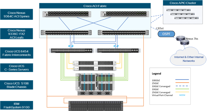
Physical Topology
Figure 1 provides a high-level topology of the system connectivity.
This VersaStack design utilizes Cisco UCS platform with Cisco UCS B200 M5 half-width blades and Cisco UCS C220 M5 servers connected and managed through Cisco UCS 6454 Fabric Interconnects and the integrated Cisco UCS Manager (UCSM). These high-performance servers are configured as stateless compute nodes where ESXi 6.7 U3 hypervisor is loaded using SAN (iSCSI) boot. The boot disks to store ESXi hypervisor image and configuration along with the block based datastores to host application Virtual Machines (VMs) are provisioned on the IBM Flash System 9100 storage array.
As in the non-ACI designs of VersaStack, link aggregation technologies play an important role in VersaStack with ACI solution providing improved aggregate bandwidth and link resiliency across the solution stack. Cisco UCS, and Cisco Nexus 9000 platforms support active port channeling using 802.3ad standard Link Aggregation Control Protocol (LACP). In addition, the Cisco Nexus 9000 series features virtual Port Channel (vPC) capability which allows links that are physically connected to two different Cisco Nexus devices to appear as a single "logical" port channel.
This design has following physical connectivity between the components of VersaStack:
· 4 X 10 Gb Ethernet connections port-channeled between the Cisco UCS 5108 Blade Chassis and the Cisco UCS Fabric Interconnects
· 25 Gb Ethernet connections between the Cisco UCS C-Series rackmounts and the Cisco UCS Fabric Interconnects
· 100 Gb Ethernet connections port-channeled between the Cisco UCS Fabric Interconnect and Cisco Nexus 9000 ACI leaf’s
· 100 Gb Ethernet connections between the Cisco Nexus 9000 ACI Spine’s and Nexus 9000 ACI Leaf’s
· 25 Gb Ethernet connections between the Cisco Nexus 9000 ACI Leaf’s and IBM Flash System 9100 storage array for iSCSI block storage access.
Figure 1 VersaStack with Cisco ACI and IBM FS9100 Physical Topology
This document guides customers through the low-level steps for deploying the base architecture. These procedures explain everything from physical cabling to network, compute, and storage device configurations.
For detailed information about the VersaStack design, see:
Software Revisions
Table 1 lists the hardware and software versions used for the solution validation.
It is important to note that Cisco, IBM, and VMware have interoperability matrices that should be referenced to determine support for any specific implementation of VersaStack. See the following links for more information:
· IBM System Storage Interoperation Center
· Cisco UCS Hardware and Software Interoperability Tool
Table 1 Hardware and Software Revisions
| Layer |
Device |
Image |
Comments |
| Compute |
Cisco UCS Fabric Interconnects 6400 Series, Cisco UCS B200 M5 & Cisco UCS C220 M5 |
4.0 (4e) |
Includes the Cisco UCS-IOM 2208XP, Cisco UCS Manager, Cisco UCS VIC 1440 and Cisco UCS VIC 1457 |
| Cisco nenic Driver |
1.0.29.0 |
Ethernet driver for Cisco VIC |
|
| Cisco nfnic Driver |
4.0.0.40 |
FCoE driver for Cisco VIC |
|
| Network |
Cisco APIC |
4.2(1j) |
ACI Controller |
| Cisco Nexus Switches |
N9000-14.2(1j) |
ACI Leaf Switches |
|
|
|
Cisco ExternalSwitch |
1.1 |
UCS Integration with ACI |
| Storage |
IBM FlashSystem 9110 |
8.2.1.6 |
Software version |
| Virtualization |
VMware vSphere ESXi |
6.7 update 3 |
Software version |
| VMware vCenter |
6.7 update 3 |
Software version |
|
| Cisco ACI Plugin |
4.2.1000.10 |
VMware ACI Integration |
Configuration Guidelines
This document provides the details for configuring a fully redundant, highly available VersaStack configuration. Therefore, appropriate references are provided to indicate the component being configured at each step, such as 01 and 02 or A and B. For example, the Cisco UCS fabric interconnects are identified as FI-A or FI-B. This document is intended to enable customers and partners to fully configure the customer environment and during this process, various steps may require the use of customer-specific naming conventions, IP addresses, and VLAN schemes, as well as appropriate MAC addresses.
![]() This document details network (Nexus), compute (Cisco UCS), virtualization (VMware) and related IBM FS9100 storage configurations (host to storage system connectivity).
This document details network (Nexus), compute (Cisco UCS), virtualization (VMware) and related IBM FS9100 storage configurations (host to storage system connectivity).
Table 2 lists the VLANs necessary for deployment as outlined in this guide. In this table, VS indicates dynamically assigned VLANs from the APIC-Controlled Microsoft Virtual Switch.
Table 2 VersaStack Necessary VLANs
| VLAN Name |
VLAN |
Subnet |
Usage |
| Out-of-Band-Mgmt |
111 |
192.168.160.0/22 |
VLAN for out-of-band management interfaces |
| IB-MGMT |
11 |
10.1.160.0/22 |
Management VLAN to access and manage the servers |
| iSCSI-A |
3161 |
10.29.161.0/24 |
iSCSI-A path for booting both B Series and C Series servers and datastore access |
| iSCSI-B |
3162 |
10.29.162.0/24 |
iSCSI-B path for booting both B Series and C Series servers and datastore access |
| vMotion |
3173 |
10.29.173.0/24 |
VMware vMotion traffic |
| Native-VLAN |
2 |
N/A |
VLAN 2 used as Native VLAN instead of default VLAN (1) |
| App-vDS-VLANs |
1400-1499 |
172.20.100.0/22 172.20.104.0/22 |
VLANs for Application VM Interfaces residing in vDS based port groups |
Physical Infrastructure
This section explains the cabling examples used for the validated topology in the environment. To make connectivity clear in this example, the tables include both the local and remote port locations.
VersaStack Cabling
The information in this section is provided as a reference for cabling the equipment in VersaStack environment. To simplify the documentation, the architecture shown in Figure 1 is broken down into network, compute and storage related physical connectivity details.
![]() You can choose interfaces and ports of their liking but failure to follow the exact connectivity shown in figures below will result in changes to the deployment procedures since specific port information is used in various configuration steps.
You can choose interfaces and ports of their liking but failure to follow the exact connectivity shown in figures below will result in changes to the deployment procedures since specific port information is used in various configuration steps.
This document assumes that out-of-band management ports are plugged into an existing management infrastructure at the deployment site. These interfaces will be used in various configuration steps. Make sure to use the cabling directions in this section as a guide.
Figure 2 details the cable connections used in the validation lab for the VersaStack with Cisco ACI and IBM FlashSystem 9100 storage.
![]() The Nexus 9336C-FX2 switches used in this design support 10/25/40/100 Gbps on all the ports. The switch supports breakout interfaces, each 100Gbps port on the switch can be split in to 4 X 25Gbps interfaces. The QSFP breakout cable has been leveraged to connect 25Gbps iSCSI ethernet ports on the FS9100 storage array to the 100Gbps QSFP port on the switch end. With this connectivity, IBM SFP transceiver on the FS9100 are not required.
The Nexus 9336C-FX2 switches used in this design support 10/25/40/100 Gbps on all the ports. The switch supports breakout interfaces, each 100Gbps port on the switch can be split in to 4 X 25Gbps interfaces. The QSFP breakout cable has been leveraged to connect 25Gbps iSCSI ethernet ports on the FS9100 storage array to the 100Gbps QSFP port on the switch end. With this connectivity, IBM SFP transceiver on the FS9100 are not required.
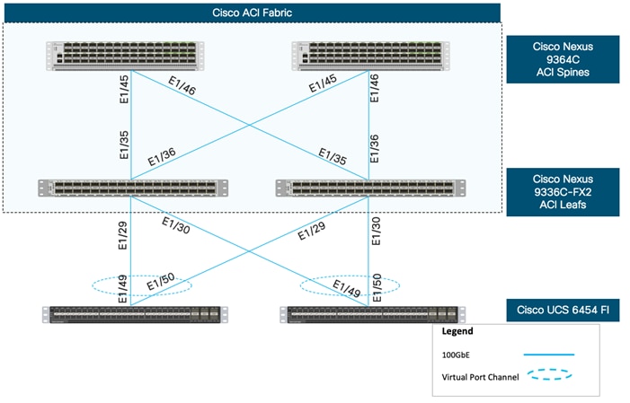
Cisco Nexus Leaf connectivity
For physical connectivity details of Cisco Leaf switches in the ACI fabric, refer to Figure 3.
Figure 3 Network Connectivity – ACI Leaf Cabling Information
The following tables list the specific port connections with the cables used in the deployment of the VersaStack network are provided below.
Table 3 Cisco Nexus 9336C-FX2 A (Leaf) Cabling Information
| Local Device |
Local Port |
Connection |
Remote Device |
Remote Port |
| Cisco Nexus 9336C-FX2 A
|
Eth1/29 |
100GbE |
Cisco UCS 6454 FI A |
Eth1/49 |
| Eth1/30 |
100GbE |
Cisco UCS 6454 FI B |
Eth 1/49 |
|
| Eth1/35 |
100GbE |
Cisco 9364C A (Spine) |
Eth 1/45 |
|
| Eth1/36 |
100GbE |
Cisco 9364C B (Spine) |
Eth 1/45 |
|
| MGMT0 |
GbE |
GbE management switch |
Any |
|
| Eth1/11/1* |
25GbE |
IBM FS9100 node 1 |
Port 5 |
|
| Eth1/11/2* |
25GbE |
IBM FS9100 node 2 |
Port 5 |
Table 4 Cisco Nexus 9336C-FX2 B (Leaf) Cabling Information
| Local Device |
Local Port |
Connection |
Remote Device |
Remote Port |
| Cisco Nexus 9336C-FX2 B
|
Eth1/29 |
100GbE |
Cisco UCS 6454 FI A |
Eth1/50 |
| Eth1/30 |
100GbE |
Cisco UCS 6454 FI B |
Eth 1/50 |
|
| Eth1/35 |
100GbE |
Cisco 9364C A (Spine) |
Eth 1/46 |
|
| Eth1/36 |
100GbE |
Cisco 9364C B (Spine) |
Eth 1/46 |
|
| MGMT0 |
GbE |
GbE management switch |
Any |
|
| Eth1/11/1* |
25GbE |
IBM FS9100 node 1 |
Port 6 |
|
| Eth1/11/2* |
25GbE |
IBM FS9100 node 2 |
Port 6 |
![]() * Dynamic Breakout Posts - Breakout enables a 100Gb port to be split into four independent and logical 25Gb ports. Cisco QSFP-4SFP25G cable is used to connect the ports.
* Dynamic Breakout Posts - Breakout enables a 100Gb port to be split into four independent and logical 25Gb ports. Cisco QSFP-4SFP25G cable is used to connect the ports.
Cisco UCS Compute connectivity
For physical connectivity details of Cisco UCS, refer to Figure 4.
Figure 4 VersaStack Compute Connectivity
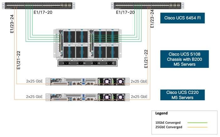
Table 5 Cisco UCS 6454 A Cabling Information
| Local Device |
Local Port |
Connection |
Remote Device |
Remote Port |
| Cisco UCS 6454 FI A
|
Eth1/17 |
10GbE |
Cisco UCS Chassis 2208XP FEX A |
IOM 1/1 |
| Eth1/18 |
10GbE |
Cisco UCS Chassis 2208XP FEX A |
IOM 1/2 |
|
| Eth1/19 |
10GbE |
Cisco UCS Chassis 2208XP FEX A |
IOM 1/3 |
|
| Eth1/20 |
10GbE |
Cisco UCS Chassis 2208XP FEX A |
IOM 1/4 |
|
| Eth1/21 |
25GbE |
Cisco UCS C220 M5 |
Port 1 |
|
| Eth1/22 |
25GbE |
Cisco UCS C220 M5 |
Port 3 |
|
| Eth1/49 |
100GbE |
Cisco Nexus 9336C-FX2 A |
Eth1/29 |
|
| Eth1/50 |
100GbE |
Cisco Nexus 9336C-FX2 B |
Eth1/29 |
|
| MGMT0 |
GbE |
GbE management switch |
Any |
|
| L1 |
GbE |
Cisco UCS 6454 FI B |
L1 |
![]() Ports 1-8 on the Cisco UCS 6454 are unified ports that can be configured as Ethernet or as Fibre Channel ports. Server ports should be initially deployed starting at least with port 1/9 to give flexibility for FC port needs, and ports 49-54 are not configurable for server ports. Also, ports 45-48 are the only configurable ports for 1Gbps connections that may be needed to a network switch.
Ports 1-8 on the Cisco UCS 6454 are unified ports that can be configured as Ethernet or as Fibre Channel ports. Server ports should be initially deployed starting at least with port 1/9 to give flexibility for FC port needs, and ports 49-54 are not configurable for server ports. Also, ports 45-48 are the only configurable ports for 1Gbps connections that may be needed to a network switch.
Table 6 Cisco UCS 6454 B Cabling Information
| Local Device |
Local Port |
Connection |
Remote Device |
Remote Port |
| Cisco UCS 6454 FI B
|
Eth1/17 |
10GbE |
Cisco UCS Chassis 2208XP FEX B |
IOM 1/1 |
| Eth1/18 |
10GbE |
Cisco UCS Chassis 2208XP FEX B |
IOM 1/2 |
|
| Eth1/19 |
10GbE |
Cisco UCS Chassis 2208XP FEX B |
IOM 1/3 |
|
| Eth1/20 |
10GbE |
Cisco UCS Chassis 2208XP FEX B |
IOM 1/4 |
|
| Eth1/21 |
25GbE |
Cisco UCS C220 M5 |
Port 2 |
|
| Eth1/22 |
25GbE |
Cisco UCS C220 M5 |
Port 4 |
|
| Eth1/49 |
100GbE |
Cisco Nexus 9336C-FX2 A |
Eth1/30 |
|
| Eth1/50 |
100GbE |
Cisco Nexus 9336C-FX2 B |
Eth1/30 |
|
| MGMT0 |
GbE |
GbE management switch |
Any |
|
| L1 |
GbE |
Cisco UCS 6454 FI A |
L1 |
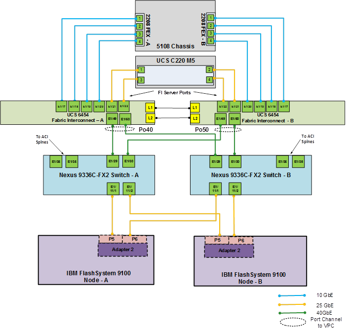
IBM FS9100 Connectivity to Nexus Switches
For physical connectivity details of IBM FS9100 node canisters to the Cisco Nexus Switches, refer to Figure 5. This deployment shows connectivity for a pair of IBM FS9100 node canisters. Additional nodes can be connected to open ports on Nexus switches as needed.
Figure 5 IBM FS9100 Connectivity to Nexus 9k Switches

Table 7 IBM FS9100 Connectivity to the Nexus Switches
| Local Device |
Local Port |
Connection |
Remote Device |
Remote Port |
| IBM FS9100 node 1 |
Port 5 |
25GbE |
Cisco Nexus 9336C-FX2 A |
Eth1/11/1* |
| Port 6 |
25GbE |
Cisco Nexus 9336C-FX2 B |
Eth1/11/1* |
|
| IBM FS9100 node 2 |
Port 5 |
25GbE |
Cisco Nexus 9336C-FX2 A |
Eth1/11/2* |
| Port 6 |
25GbE |
Cisco Nexus 9336C-FX2 B |
Eth1/11/2* |
![]() * Breakout interfaces with one 100G QSFP port on the Nexus 9336C-FX2 is split in to 4 X 25Gbps SFP interfaces connected to the IBM FS9100. Cisco QSFP100G-4SFP25G breakout cable has been leveraged for this connectivity.
* Breakout interfaces with one 100G QSFP port on the Nexus 9336C-FX2 is split in to 4 X 25Gbps SFP interfaces connected to the IBM FS9100. Cisco QSFP100G-4SFP25G breakout cable has been leveraged for this connectivity.
This section provides a detailed procedure for configuring the Cisco ACI fabric for use in the environment and is written where the components are added to an existing Cisco ACI fabric as several new ACI tenants. Required fabric setup is verified, but previous configuration of the ACI fabric is assumed.
In ACI, both spine and leaf switches are configured using the APIC, individual configuration of the switches is not required. The Cisco APIC discovers the ACI infrastructure switches using LLDP and acts as the central control and management point for the entire configuration.
ACI Fabric Core
The design assumes that an ACI fabric of Spine switches and APICs already exists in the customer’s environment, so this document verifies the existing setup but does not cover the configuration required to bring the initial ACI fabric online.
![]() Physical cabling should be completed by following the diagram and table references found in the VersaStack cabling section.
Physical cabling should be completed by following the diagram and table references found in the VersaStack cabling section.
Cisco Application Policy Infrastructure Controller (APIC) - Verification
Before adding leaf switches to connect to a new Cisco VersaStack environment, review the topology by completing the following steps:
![]() This sub-section verifies the setup of the Cisco APIC. Cisco recommends a cluster of at least 3 APICs controlling an ACI Fabric.
This sub-section verifies the setup of the Cisco APIC. Cisco recommends a cluster of at least 3 APICs controlling an ACI Fabric.
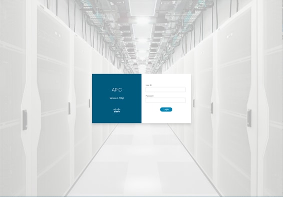
1. Log into the APIC GUI using a web browser, by browsing to the out of band IP address configured for APIC. Login with the admin user id and password.
2. Take the appropriate action to close any warning or information screens.
3. At the top in the APIC home page, select the System tab followed by Controllers.
4. On the left, select the Controllers folder. Verify that at least 3 APICs are available and have redundant connections to the fabric.
Cisco ACI Fabric Discovery
This section details the steps for adding the two Nexus 9336C-FX2 leaf switches to the Fabric. This procedure is assuming that a VersaStack with dedicated leaves is being added to an established ACI fabric. If the two Nexus 9336C-FX2 leaves have already been added to the fabric, continue to the next section. These switches are automatically discovered in the ACI Fabric and are manually assigned node IDs. To add Nexus 9336C-FX2 leaf switches to the ACI fabric, follow these steps:
1. At the top in the APIC home page, select the Fabric tab and make sure Inventory under Fabric is selected.
2. In the left pane, select and expand Fabric Membership.
3. The two 9336C-FX2 Leaf Switches will be listed on the Fabric Membership page within the Nodes Pending Registration tab as Node ID 0 as shown:
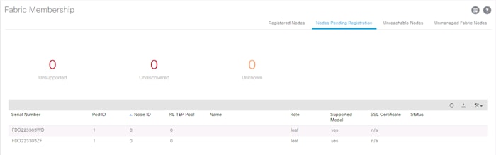
![]() For auto-discovery to occur by the APIC, the leaves will need to be running an ACI mode switch software release. For instructions on migrating from NX-OS, please refer to: https://www.cisco.com/c/en/us/td/docs/switches/datacenter/aci/apic/sw/kb/b_KB_Converting_N9KSwitch_NXOSStandaloneMode_to_ACIMode.html
For auto-discovery to occur by the APIC, the leaves will need to be running an ACI mode switch software release. For instructions on migrating from NX-OS, please refer to: https://www.cisco.com/c/en/us/td/docs/switches/datacenter/aci/apic/sw/kb/b_KB_Converting_N9KSwitch_NXOSStandaloneMode_to_ACIMode.html
4. Connect to the two Nexus 9336C-FX2 leaf switches using serial consoles and login in as admin with no password (press enter). Use show inventory to get the leaf’s serial number.

5. Match the serial numbers from the leaf listing to determine the A and B switches under Fabric Membership.
6. In the APIC GUI, within Nodes Pending Registration under Fabric Membership, right click the A leaf in the list and select Register.
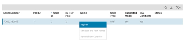
7. Enter a Node ID and a Node Name for the Leaf switch and click Register
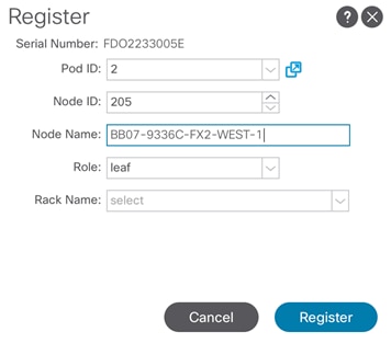
8. Repeat steps 4-7 for the B leaf in the list.
![]() During discovery, there may be some messages appearing about the leaves being inactive, these messages can be ignored.
During discovery, there may be some messages appearing about the leaves being inactive, these messages can be ignored.
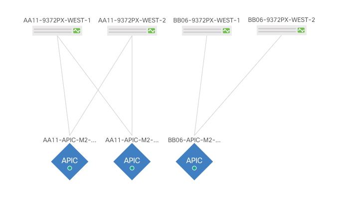
9. Click on the Pod the leaves are associated with and select the Topology tab for the Pod. The discovered ACI Fabric topology will appear. It may take a few minutes for the new Nexus 9336C-FX2 switches to appear and you will need to click the refresh button for the complete topology to appear. You may also need to move the switches around to get the arrangement that you desire.
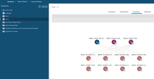
![]() The topology shown in the screenshot above is the topology of the validation lab fabric containing 8 leaf switches, 2 spine switches, and 2 APICs. The environment used is implementing an ACI Multi-Pod (not covered in this document), which places the third APIC in a remotely connected ACI Pod. Cisco recommends a cluster of at least 3 APICs in a production environment.
The topology shown in the screenshot above is the topology of the validation lab fabric containing 8 leaf switches, 2 spine switches, and 2 APICs. The environment used is implementing an ACI Multi-Pod (not covered in this document), which places the third APIC in a remotely connected ACI Pod. Cisco recommends a cluster of at least 3 APICs in a production environment.
Initial ACI Fabric Setup - Verification
This section details the steps for the initial setup of the Cisco ACI Fabric, where the software release is validated, out of band management IPs are assigned to the new leaves, NTP setup is verified, and the fabric BGP route reflectors are verified.
Software Upgrade
To upgrade the software, follow these steps:
1. In the APIC GUI, at the top select Admin -> Firmware -> Infrastructure -> Nodes.
2. This document was validated with ACI software release 4.2(1j). Select the Infrastructure tab within Firmware, and the Nodes sub-tab under Infrastructure. All switches should show the same firmware release and the release version should be at minimum n9000-14.2(1j). The switch software version should also correlate with the APIC version.
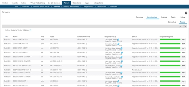
3. Click Admin > Firmware > Controller Firmware. If all APICs are not at the same release at a minimum of 4.2(1j), follow the Cisco APIC Management, Installation, Upgrade, and Downgrade Guide to upgrade both the APICs and switches if the APICs are not at a minimum release of 4.2(1j) and the switches are not at n9000-14.2(1j).
Setting Up Out-of-Band Management IP Addresses for New Leaf Switches
To set up out-of-band management IP addresses, follow these steps:
1. To add Out-of-Band management interfaces for all the switches in the ACI Fabric, select Tenants -> mgmt.
2. Expand Tenant mgmt on the left. Right-click Node Management Addresses and select Create Static Node Management Addresses.
3. Enter the node number range for the new leaf switches (205-206 in this example).
4. Select the checkbox for Out-of-Band Addresses.
5. Select default for Out-of-Band Management EPG.
6. Considering that the IPs will be applied in a consecutive range of two IPs, enter a starting IP address and netmask in the Out-of-Band IPV4 Address field.
7. Enter the Out-of-Band management gateway address in the Gateway field.
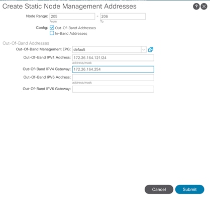
8. Click Submit, then click YES.
9. On the left, expand Node Management Addresses and select Static Node Management Addresses. Verify the mapping of IPs to switching nodes.
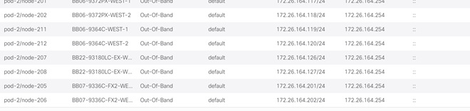
10. Direct out-of-band access to the switches is now available using SSH.
Verifying Time Zone and NTP Server
This procedure will allow customers to verify setup of an NTP server for synchronizing the fabric time. To verify the time zone and NTP server set up, follow these steps:
1. To verify NTP setup in the fabric, select and expand Fabric -> Fabric Policies -> Policies -> Pod -> Date and Time.
2. Select default. In the Datetime Format - default pane, verify the correct Time Zone is selected and that Offset State is enabled. Adjust as necessary and click Submit and Submit Changes.
3. On the left, select Policy default. Verify that at least one NTP Server is listed.
4. If desired, select enabled for Server State to enable the ACI fabric switches as NTP servers. Click Submit.
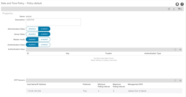
5. If necessary, on the right use the + sign to add NTP servers accessible on the out of band management subnet. Enter an IP address accessible on the out of band management subnet and select the default (Out-of-Band) Management EPG. Click Submit to add the NTP server. Repeat this process to add all NTP servers.
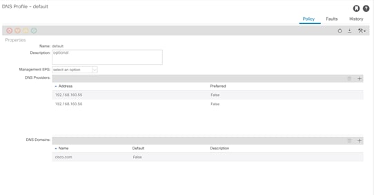
Verifying Domain Name Servers
To verify optional DNS in the ACI fabric, follow these steps:
1. Select and expand Fabric -> Fabric Policies -> Policies -> Global -> DNS Profiles -> default.
2. Verify the DNS Providers and DNS Domains.
3. If necessary, in the Management EPG drop-down, select the default (Out-of-Band) Management EPG. Use the + signs to the right of DNS Providers and DNS Domains to add DNS servers and the DNS domain name. Note that the DNS servers should be reachable from the out of band management subnet. Click SUBMIT to complete the DNS configuration.
Verifying BGP Route Reflectors
In this ACI deployment, both of the spine switches are set up as BGP route-reflectors to distribute the leaf routes throughout the fabric. To verify the BGP Route Reflector, follow these steps:
1. Select and expand System -> System Settings -> BGP Route Reflector.
2. Verify that a unique Autonomous System Number has been selected for this ACI fabric. If necessary, use the + sign on the right to add the two spines to the list of Route Reflector Nodes. Click Submit to complete configuring the BGP Route Reflector.
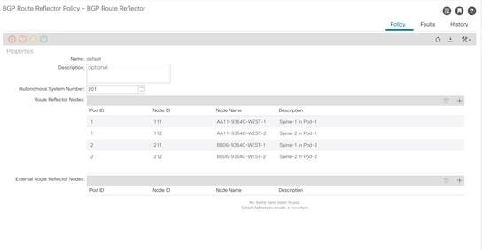
3. To verify the BGP Route Reflector has been enabled, select and expand Fabric -> Fabric Policies -> Pods -> Policy Groups. Under Policy Groups make sure a policy group has been created and select it. The BGP Route Reflector Policy field should show “default.”
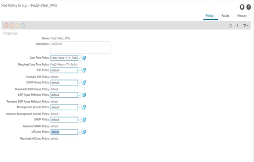
4. If a Policy Group has not been created, on the left, right-click Policy Groups under Pod Policies and select Create Pod Policy Group. In the Create Pod Policy Group window, provide an appropriate Policy Group name. Select the default BGP Route Reflector Policy. Click Submit to complete creating the Policy Group.
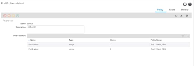
5. On the left expand Pods -> Profiles and select Pod Profile default.
6. Verify that the created Policy Group or the Fabric Policy Group identified above is selected. If the Fabric Policy Group is not selected, view the drop-down list to select it and click Submit.
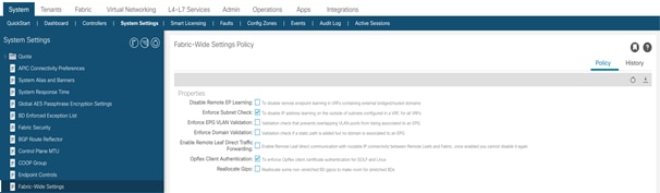
Verifying Fabric Wide Enforce Subnet Check for IP & MAC Learning
In this ACI deployment, Enforce Subnet Check for IP & MAC Learning should be enabled. To verify this setting, follow these steps:
1. Select and expand System -> System Settings -> Fabric Wide Setting.
2. Ensure that Enforce Subnet Check is selected, check the box if it is not selected.
3. Select Opflex Client Authentication. (Needed if configuring Cisco AVE)
4. Click Submit.
Fabric Access Policy Setup
This section details the steps to create various access policies creating parameters for CDP, LLDP, LACP, etc. These policies are used during vPC and VMM domain creation. In an existing fabric, these policies may already exist.
The following policies will be setup during the Fabric Access Policy Setup:
| Access Interface Policies |
Purpose |
Policy Name |
| Link Level Policies |
Sets link to 100Gbps |
100Gbps-Link |
| Sets link to 40Gbps |
40Gbps-Link |
|
| Sets link to 25Gbps |
25Gbps-Link |
|
| Sets link to 10Gbps |
10Gbps-Link |
|
| Sets link to 1Gbps |
1Gbps-Link |
|
| CDP Interface Policies |
Enables CDP |
CDP-Enabled |
| Disables CDP |
CDP-Disabled |
|
| LLDP Interface Policies |
Enables LLDP |
LLDP-Enabled |
| Disables LLDP |
LLDP-Disabled |
|
| Port Channel Policies |
Sets LACP Mode |
LACP-Active |
| Sets MAC Pinning |
MAC-Pinning |
|
| Layer 2 Interface Policies |
Specifies VLAN Scope as Port Local |
VLAN-Scope-Local |
| Specifies VLAN Scope as Global |
VLAN-Scope-Global |
|
| Firewall Policies |
Disables Firewall |
Firewall-Disabled |
| Spanning Tree Policies |
Enables BPDU Filter and Guard |
BPDU-FG-Enabled |
| Disables BPDU Filter and Guard |
BPDU-FG-Disabled |
The existing policies can be used if configured the same way as listed. To define fabric access policies, follow these steps:
1. Log into the APIC AGUI.
2. In the APIC UI, select and expand Fabric -> Access Policies -> Policies -> Interface.
Create Link Level Policies
This procedure will create link level policies for setting up the 1Gbps, 10Gbps, and 40Gbps link speeds. To create the link level policies, follow these steps:
1. In the left pane, right-click Link Level and select Create Link Level Policy.
2. Name the policy as 1Gbps-Link and select the 1Gbps Speed.
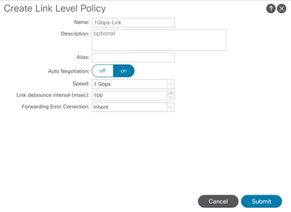
3. Click Submit to complete creating the policy.
4. In the left pane, right-click Link Level and select Create Link Level Policy.
5. Name the policy 10Gbps-Link and select the 10Gbps Speed.
6. Click Submit to complete creating the policy.
7. In the left pane, right-click Link Level and select Create Link Level Policy.
8. Name the policy 25Gbps-Link and select the 25Gbps Speed.
9. Click Submit to complete creating the policy.
10. In the left pane, right-click Link Level and select Create Link Level Policy.
11. Name the policy 40Gbps-Link and select the 40Gbps Speed.
12. Click Submit to complete creating the policy.
13. In the left pane, right-click Link Level and select Create Link Level Policy.
14. Name the policy 100Gbps-Link and select the 100Gbps Speed.
15. Click Submit to complete creating the policy.
16. Verify the policies are created successfully.
Create CDP Policy
This procedure creates policies to enable or disable CDP on a link. To create a CDP policy, follow these steps:
1. In the left pane, right-click CDP interface and select Create CDP Interface Policy.
2. Name the policy as CDP-Enabled and enable the Admin State.
3. Click Submit to complete creating the policy.
4. In the left pane, right-click the CDP Interface and select Create CDP Interface Policy.
5. Name the policy CDP-Disabled and disable the Admin State.
6. Click Submit to complete creating the policy.
Create LLDP Interface Policies
This procedure will create policies to enable or disable LLDP on a link. To create an LLDP Interface policy, follow these steps:
1. In the left pane, right-click LLDP lnterface and select Create LLDP Interface Policy.
2. Name the policy as LLDP-Enabled and enable both Transmit State and Receive State.
3. Click Submit to complete creating the policy.
4. In the left, right-click the LLDP lnterface and select Create LLDP Interface Policy.
5. Name the policy as LLDP-Disabled and disable both the Transmit State and Receive State.
6. Click Submit to complete creating the policy.
Create Port Channel Policy
This procedure will create policies to set LACP active mode configuration and the MAC-Pinning mode configuration. To create the Port Channel policy, follow these steps:
1. In the left pane, right-click Port Channel and select Create Port Channel Policy.
2. Name the policy as LACP-Active and select LACP Active for the Mode. Do not change any of the other values.
3. Click Submit to complete creating the policy.
4. In the left pane, right-click Port Channel and select Create Port Channel Policy.
5. Name the policy as MAC-Pinning and select MAC Pinning for the Mode. Do not change any of the other values.
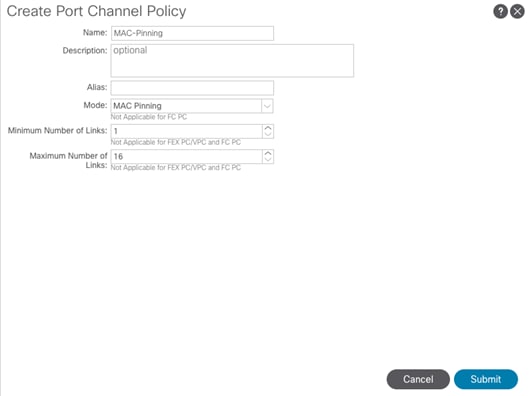
6. Click Submit to complete creating the policy.
Create BPDU Filter/Guard Policies
This procedure will create policies to enable or disable BPDU filter and guard. To create a BPDU filter/Guard policy, follow these steps:
1. In the left pane, right-click Spanning Tree Interface and select Create Spanning Tree Interface Policy.
2. Name the policy as BPDU-FG-Enabled and select both the BPDU filter and BPDU Guard Interface Controls.
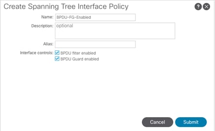
3. Click Submit to complete creating the policy.
4. In the left pane, right-click Spanning Tree Interface and select Create Spanning Tree Interface Policy.
5. Name the policy as BPDU-FG-Disabled and make sure both the BPDU filter and BPDU Guard Interface Controls are cleared.
6. Click Submit to complete creating the policy.
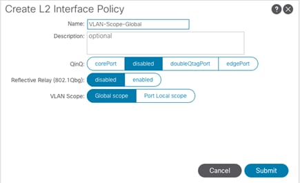
Create VLAN Scope Policy
To create policies to enable port local scope for all the VLANs, follow these steps:
1. In the left pane, right-click the L2 Interface and select Create L2 Interface Policy.
2. Name the policy as VLAN-Scope-Local and make sure Port Local scope is selected for VLAN Scope. Do not change any of the other values.
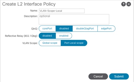
3. Click Submit to complete creating the policy.
4. Repeat steps 1–3 to create a VLAN-Scope-Global Policy and make sure Global scope is selected for VLAN Scope. Do not change any of the other values. See below.
Create Firewall Policy
To create policies to disable a firewall, follow these steps:
1. In the left pane, right-click Firewall and select Create Firewall Policy.
2. Name the policy Firewall-Disabled and select Disabled for Mode. Do not change any of the other values.
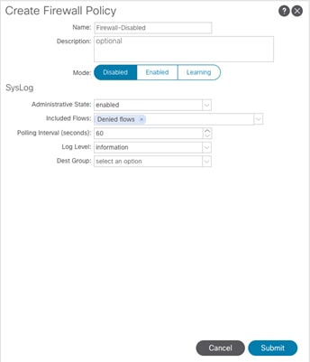
3. Click Submit to complete creating the policy.
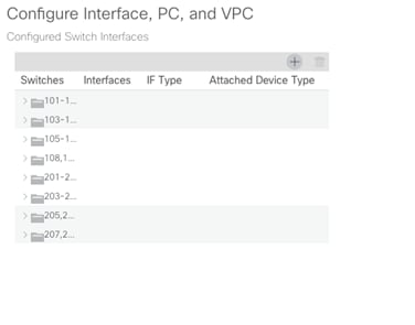
Create Virtual Port Channels (vPCs)
In this section, access layer connectivity is established between the ACI fabric and the Cisco UCS Domain for VersaStack. The Cisco UCS Domain consists of a pair of Cisco UCS Fabric Interconnects (FI-A, FI-B) – multiple Cisco UCS (rack, blade) servers can connect into a pair of Cisco UCS Fabric Interconnects.
To enable this connectivity, two virtual Port Channels (vPCs) are created on a pair of newly deployed Leaf switches (see earlier section) to each Cisco UCS Fabric Interconnect (FI-A, FI-B).
Follow these steps to create vPCs from the newly deployed ACI leaf switches to the first UCS Fabric Interconnects.
vPC – Cisco UCS Fabric Interconnects
The VLANs configured for Cisco UCS are listed in Table 8 .
Figure 6 Cisco UCS Fabric Interconnects

Table 8 EPG VLANs to Cisco UCS Compute Domain
| vPC to Cisco UCS Fabric Interconnects |
VLAN Name & ID |
VLAN ID Name Usage |
|
Domain Name: VSV-UCS_Domain
Domain Type: External Bridged (L2) Domain
VLAN Scope: Port-Local
Allocation Type: Static
VLAN Pool Name: VSV-UCS_Domain_vlans
|
Native VLAN (2) |
VLAN 2 used as Native VLAN instead of default VLAN (1) |
| IB-MGMT-VLAN (11) |
Management VLAN to access and manage the servers |
|
| vMotion (3173) |
VMware vMotion traffic |
|
| iSCSI-A (3161) |
iSCSI-A path for booting both UCS B-Series and C-Series servers and datastore access |
|
| iSCSI-B (3162) |
iSCSI-B path for booting both UCS B-Series and C-Series servers and datastore access |
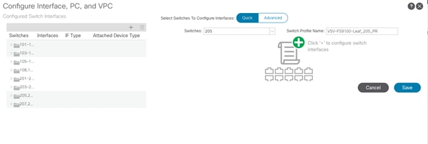
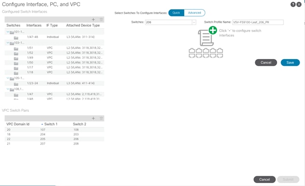
To setup vPCs for connectivity to the Cisco UCS Fabric Interconnects, follow these steps:
1. In the APIC GUI, at the top select Fabric -> Access Policies -> Quick Start.
2. In the right pane select Configure an interface, PC and VPC.
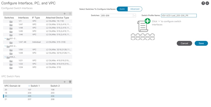
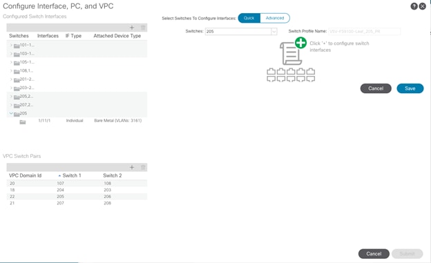
3. In the configuration window, configure a VPC domain between the leaf switches by clicking “+” under VPC Switch Pairs.
4. Enter a VPC Domain ID (22 in this example).
5. From the drop-down list, select Switch A and Switch B IDs to select the two leaf switches.
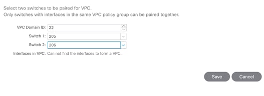
6. Click Save.
7. Click the “+” under Configured Switch Interfaces.
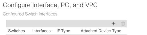
8. From the Switches drop-down list on the right, select both the leaf switches being used for this vPC.
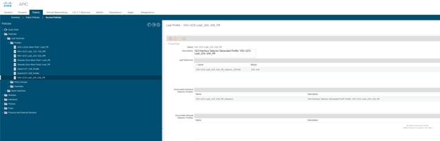
9. Change the system generated Switch Profile Name to your local naming convention, “VSV-UCS-Leaf_205-206_PR” in this case.
10. Click ![]() to add switch interfaces.
to add switch interfaces.
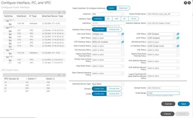
11. Configure various fields as shown in the figure below. In this screenshot, port 1/29 on both leaf switches is connected to UCS Fabric Interconnect A using 100 Gbps links.
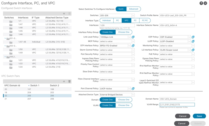
12. Click Save.
13. Click Save again to finish the configuring switch interfaces.
14. Click Submit.
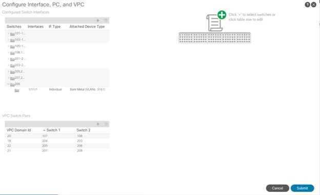
15. From the right pane, select Configure interface, PC and VPC.
16. Select the switches configured in the last step under Configured Switch Interfaces.
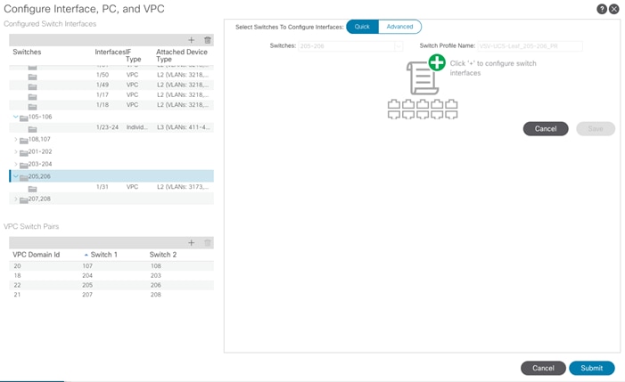
17. Click ![]() on the right to add switch interfaces.
on the right to add switch interfaces.
18. Configure various fields as shown in the screenshot. In this screenshot, port 1/30 on both leaf switches is connected to UCS Fabric Interconnect B using 100 Gbps links. Instead of creating a new domain, the External Bridged Device created in the last step (VSV-UCS_Domain) is attached to the FI-B as shown below.
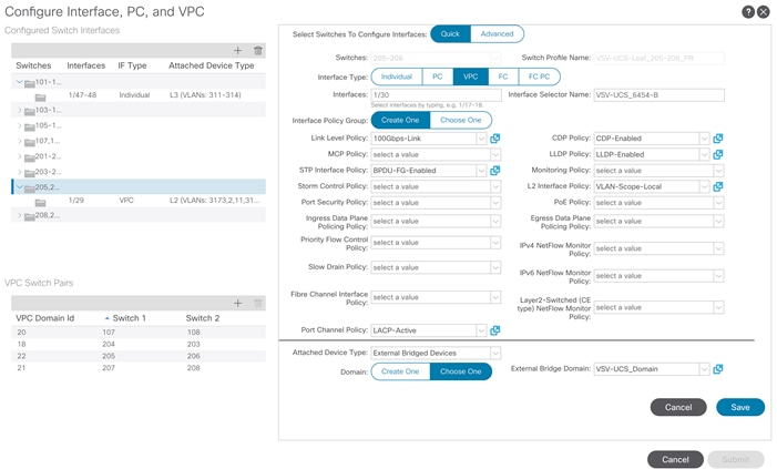
19. Click Save.
20. Click Save again to finish the configuring switch interfaces.
21. Click Submit.
22. Optional: Repeat this procedure to configure any additional UCS domains. For a uniform configuration, the External Bridge Domain (UCS) will be utilized for all the Fabric Interconnects.
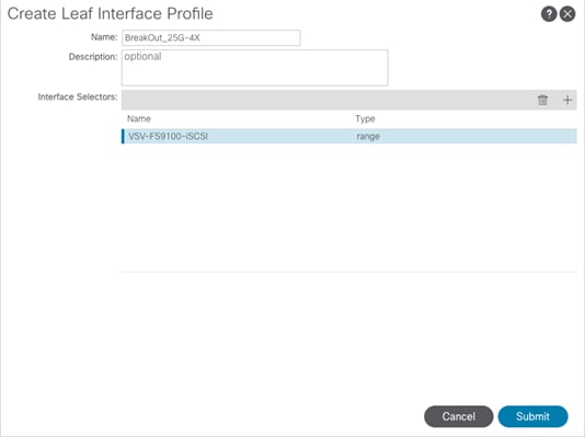
Configure Breakout Ports for IBM FS9100 iSCSI Connectivity
In this design, a breakout cable is used to connect the 25Gbps iSCSI ethernet ports on the FS9100 storage array to the 100Gbps QSFP port on the Nexus Leaf Switch end. With this connectivity, IBM SFP transceivers on the FS9100 are not required.
To configure a Breakout Leaf Port with a Leaf Interface Profile, associate the profile with a switch, and configure the sub ports, follow these steps:
![]() Connectivity between the Nexus switches and IBM FS9100 for iSCSI access depends on the Nexus 9000 switch model used within the architecture. If other supported models of Nexus switches with 25Gbps capable SFP ports are used, breakout cable is not required and ports from the switch to IBM FS9100 can be connected directly using the SFP transceivers on both sides.
Connectivity between the Nexus switches and IBM FS9100 for iSCSI access depends on the Nexus 9000 switch model used within the architecture. If other supported models of Nexus switches with 25Gbps capable SFP ports are used, breakout cable is not required and ports from the switch to IBM FS9100 can be connected directly using the SFP transceivers on both sides.
1. On the menu bar, choose Fabric > External Access Policies.
2. In the Navigation pane, expand Interfaces and Leaf Interfaces and Profiles.
3. Right-click Profiles and choose Create Leaf Interface Profile.
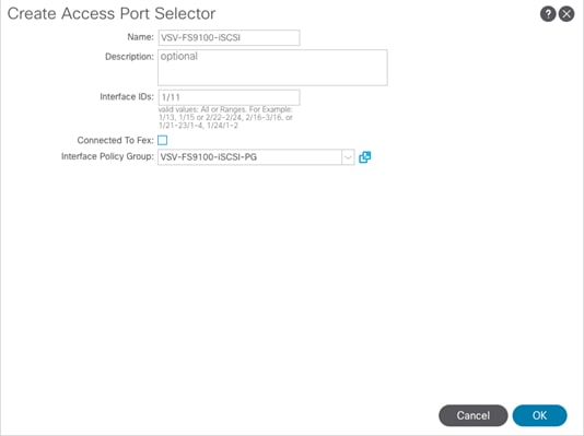
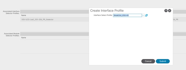
4. Type the name and optional description, click the + symbol on Interface Selectors
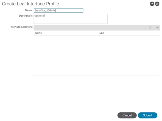
5. Perform the following:
a. Type a name (and optional description) for the Access Port Selector.
b. In the Interface IDs field, type the slot and port for the breakout port.
c. In the Interface Policy Group field, click the down arrow and choose Create Leaf Breakout Port Group.
d. Type the name (and optional description) for the Leaf Breakout Port Group.
e. In the Breakout Map field, choose 25g-4x.
6. Click Submit.
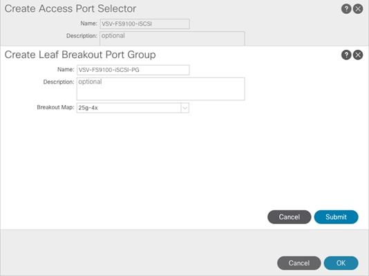
7. Click OK.
8. Click Submit.
To associate the Leaf Interface Profile to the leaf switch, perform the following steps:
1. In the APIC Fabric tab, click Access Policies.
2. Expand Switches and Leaf Switches, and Profiles.
3. Select VSV-UCS-Leaf_205-206_PR profile that was created earlier for the two VersaStack Leaf switches.
4. Under Associated Interface Selector Profiles.
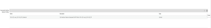
5. Use the + sign on the right to add the breakout profile to the leaf switches.
6. Click Submit.
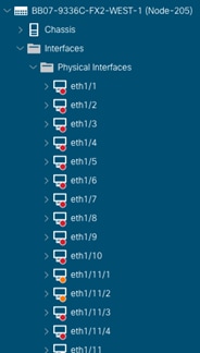
7. To verify the breakout port has been split into four sub ports, perform the following steps:
8. On the Menu bar, click Fabric -> Inventory.
9. On the Navigation bar, Click the Pod and Leaf where the breakout port is located.
10. Expand Interfaces and Physical Interfaces.
11. Four ports should be displayed where the breakout port was configured.
Configure Individual Ports for FS9100 iSCSI Access
This section details the steps to setup ACI configuration for IBM FS9100 nodes to provide iSCSI connectivity. The physical connectivity between IBM FS9100 nodes and Cisco Nexus 93336C-FX2 switches is shown in Figure 7:
Figure 7 Physical Connectivity
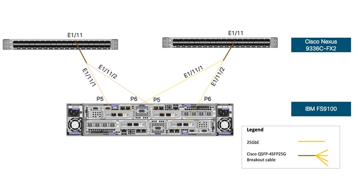
Table 9 lists the configuration parameters for setting up the iSCSI links.
Table 9 EPG VLANs to IBM FS9100 Storage Nodes
| vPC to Cisco UCS Fabric Interconnects |
VLAN Name & ID |
VLAN ID Name Usage |
| Domain Name: VSV-FS9100-A VSV-FS9100-B
Domain Type: Bare Metal (Physical)
VLAN Scope: Port-Local
Allocation Type: Static
VLAN Pool Name: VSV-FS9100-A_vlans VSV-FS9100-B_vlans
|
iSCSI-A (3161) |
Provides access to boot, application data and datastore LUNs on IBM FS9100 via iSCSI Path-A |
| iSCSI-B (3162) |
Provides access to boot, application data and datastore LUNs on IBM FS9100 via iSCSI Path-B |
Configure Ports for iSCSI-A Path
To configure ports for iSCSI-A paths, follow these steps:
1. In the APIC Advanced GUI, select Fabric > Access Policies > Quick Start.
2. In the right pane, select Configure interface, PC and VPC.
3. Click “+” under Configured Switch Interfaces.
4. Select first leaf switch from the drop-down list Switches.
5. Change the system generated Switch Profile Name to your local naming convention, “VSV-FS9100-Leaf_205_PR” in this case.
6. Click ![]() in the right pane to add switch interfaces.
in the right pane to add switch interfaces.
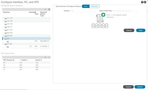
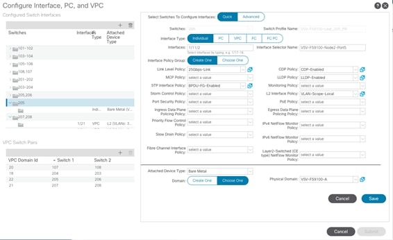
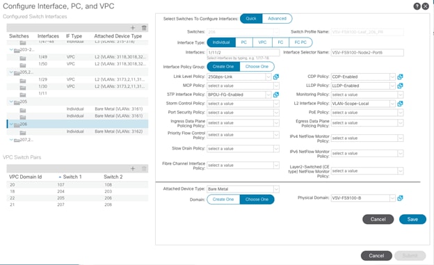
7. Configure various fields as shown in the figure below. In this screen shot, port 1/11/1 is connected to IBM FS9100 Node1 Port5 using 25Gbps links. The details of the port connectivity can be obtained from Table 7 .
8. Click SAVE
9. Click SAVE again to finish configuring the switch interfaces.
10. Click SUBMIT.
11. From the right pane, select Configure interface, PC and VPC.
12. Select the switch configured in the last step under Configured Switch Interfaces.
13. Click ![]() on the right to add switch interfaces
on the right to add switch interfaces
14. Configure various fields as shown in the figure below. In this screen shot, port 1/11/2 is connected to IBM FS9100 Node2 Port5 using 25Gbps links. Instead of creating a new domain, the Physical Domain created in the last step (VSV-FS9100-A) is attached to the IBM FS9100 Node 2 as shown below.
15. Click SAVE.
16. Click SAVE again to finish configuring switch interfaces.
17. Click SUBMIT.
Configure Ports for iSCSI-B Path
To configure ports for iSCSI-B paths, follow these steps:
1. In the APIC Advanced GUI, select Fabric > Access Policies > Quick Start.
2. In the right pane, select Configure interface, PC and VPC.
3. Click “+” under Configured Switch Interfaces.
4. Select second leaf switch from the drop-down list Switches.
5. Change the system generated Switch Profile Name to your local naming convention, “VSV-FS9100-Leaf_206_PR” in this case.
6. Click ![]() in the right pane to add switch interfaces.
in the right pane to add switch interfaces.

7. Configure various fields as shown in the figure below. In this screen shot, port 1/11/1 is connected to IBM FS9100 Node1 Port6 using 25Gbps links. The details of the port connectivity can be obtained from Table 7 .
8. Click SAVE.
9. Click SAVE again to finish the configuring switch interfaces
10. Click SUBMIT.
11. From the right pane, select Configure interface, PC and VPC.
12. Select the switch configured in the last step under Configured Switch Interfaces
13. Click ![]() on the right to add switch interfaces
on the right to add switch interfaces
14. Configure various fields as shown in the figure below. In this screen shot, port 1/11/2 is connected to IBM SVC Node2 Port6 using 25Gbps links. Instead of creating a new domain, the Physical Domain created in the last step (VSV-FS9100-B) is attached to the IBM FS9100 Node 2 as shown below.
15. Click SAVE.
16. Click SAVE again to finish the configuring switch interfaces
17. Click SUBMIT.
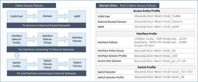
ACI Fabric Deployment – Layer 3 Routed Connectivity to Outside Networks
Complete the steps outlined in this section to establish Layer 3 connectivity or a Shared L3Out from Pod-2 to networks outside the ACI fabric. As mentioned earlier, an existing ACI Multi-Pod environment has been leveraged to setup the VersaStack ACI infrastructure.
Deployment Overview
The Shared L3Out connection is established in the system-defined common Tenant as a common resource that can be shared by multiple tenants in the ACI fabric. The connection uses four 10GbE interfaces between border leaf switches deployed earlier and pair of Nexus 7000 switches. The Nexus 7000 routers serve as the external gateway to the networks outside the fabric. OSPF is utilized as the routing protocol to exchange routes between the two networks. Some highlights of this connectivity are:
· Pair of Border Leaf switches in Pod-2 connect to a pair of Nexus 7000 routers outside the ACI fabric using 4 x 10GbE links. Nexus 7000 routers serve as a gateway to the networks outside the fabric.
· Routing protocol use to exchange routes between the ACI fabric and networks outside ACI is OSPF
· VLAN tagging is used for connectivity across the 4 links – a total of 4 VLANs for the 4 x 10GbE links. VLANs are configured on separate sub-interfaces.
· Fabric Access Policies are configured on ACI Leaf switches to connect to the External Routed domain using VLAN pool (vlans: 315-318).
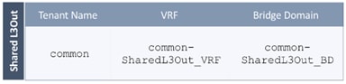
· Pod-2 uses the same Tenant (common), VRF (common-SharedL3Out_VRF) and Bridge Domain (common-SharedL3Out_BD) as Pod-1 for Shared L3Out.
· The shared L3Out created in common Tenant “provides” an external connectivity contract that can be “consumed” from any tenant.
· The Nexus 7000s connected to Pod-2 are configured to originate and send a default route via OSPF to the border leaf switches in Pod-2.
· ACI leaf switches in Pod-2 advertise tenant subnets back to Nexus 7000 switches.
· In ACI 4.0, ACI leaf switches can also advertise host-routes if it is enabled.
Create VLAN Pool for External Routed Domain
In this section, a VLAN pool is created to enable connectivity to the external networks, outside the ACI fabric. The VLANs in the pool are for the four links that connect ACI Border Leaf switches to the Nexus Gateway routers in the non-ACI portion of the customer’s network.
Table 10 VLAN Pool for Shared L3Out in Pod-2
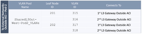
To configure a VLAN pool to connect to external gateway routers outside the ACI fabric, follow these steps:
1. Use a browser to navigate to the APIC GUI. Log in using the admin account.
2. From the top navigation menu, select Fabric > Access Policies.
3. From the left navigation pane, expand and select Pools > VLAN.
4. Right-click and select Create VLAN Pool.
5. In the Create VLAN Pool pop-up window, specify a Name (for example, SharedL3Out-West-Pod2_VLANs) and for Allocation Mode, select Static Allocation.
6. For Encap Blocks, use the [+] button on the right to add VLANs to the VLAN Pool. In the Create Ranges pop-up window, configure the VLANs that need to be configured from the Border Leaf switches to the external gateways outside the ACI fabric. Leave the remaining parameters as is.
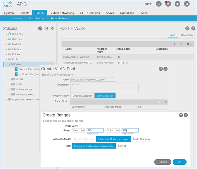
7. Click OK. Use the same VLAN ranges on the external gateway routers to connect to the ACI Fabric.
8. Click Submit to complete.
Configure Domain Type for External Routed Domain
Table 11 Domain Type for Shared L3Out in Pod-2
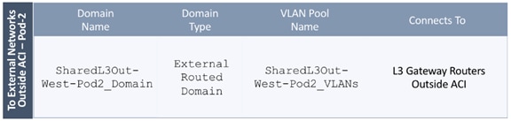
To specify the domain type to connect to external gateway routers outside the ACI fabric, follow these steps:
1. Use a browser to navigate to the APIC GUI. Log in using the admin account.
2. From the top navigation menu, select Fabric > Access Policies.
3. From the left navigation pane, expand and select Physical and External Domains > External Routed Domains.
4. Right-click External Routed Domains and select Create Layer 3 Domain.
5. In the Create Layer 3 Domain pop-up window, specify a Name for the domain. For the VLAN Pool, select the previously created VLAN Pool from the drop-down list.
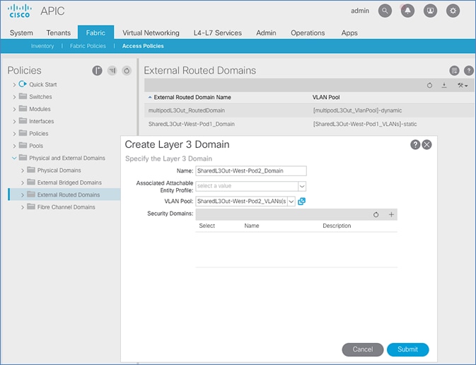
6. Click Submit to complete.
Create Attachable Access Entity Profile for External Routed Domain
Table 12 Attachable Access Entity Profile (AAEP) for Shared L3Out in Pod-2
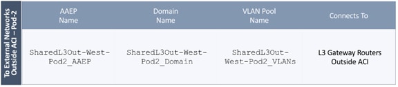
To create an Attachable Access Entity Profile (AAEP) to connect to external gateway routers outside the ACI fabric, follow these steps:
1. Use a browser to navigate to the APIC GUI. Log in using the admin account.
2. From the top navigation menu, select Fabric > Access Policies.
3. From the left navigation pane, expand and select Policies > Global > Attachable Access Entity Profiles.
4. Right-click and select Create Attachable Access Entity Profile.
5. In the Create Attachable Access Entity Profile pop-up window, specify a Name (for example, SharedL3Out-West-Pod2_AAEP).
6. For the Domains, click the [+] on the right-side of the window and select the previously created domain from the drop-down list below Domain Profile.
7. Click Update.
8. You should now see the selected domain and the associated VLAN Pool as shown below.
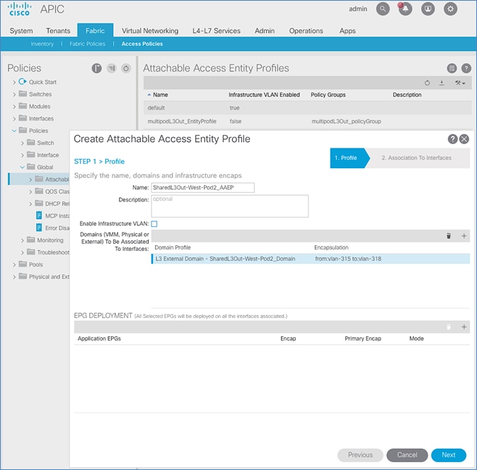
9. Click Next. This profile is not associated with any interfaces at this time. They can be associated once the interfaces are configured in an upcoming section.
10. Click Finish to complete.
Configure Interfaces to External Routed Domain
Border Leaf switches (Node ID: 201,202) in Pod-2 connect to External Gateways (Nexus 7000 series switches) using 10Gbps links, on ports 1/47 and 1/48.
Figure 8 Fabric Access Policies for Shared L3Out in Pod-2
Create Interface Policy Group for Interfaces to External Routed Domain
To create an interface policy group to connect to external gateways outside the ACI fabric, follow these steps:
1. Use a browser to navigate to the APIC GUI. Log in using the admin account.
2. From the top navigation menu, select Fabric > Access Policies.
3. From the left navigation pane, expand and select Interfaces > Leaf Interfaces > Policy Groups > Leaf Access Port.
4. Right-click and select Create Leaf Access Port Policy Group.
5. In the Create Leaf Access Port Policy Group pop-up window, specify a Name and select the applicable interface policies from the drop-down list for each field.
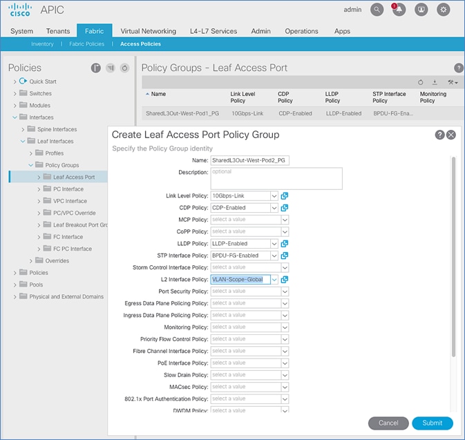
6. For the Attached Entity Profile, select the previously created AAEP to external routed domain.
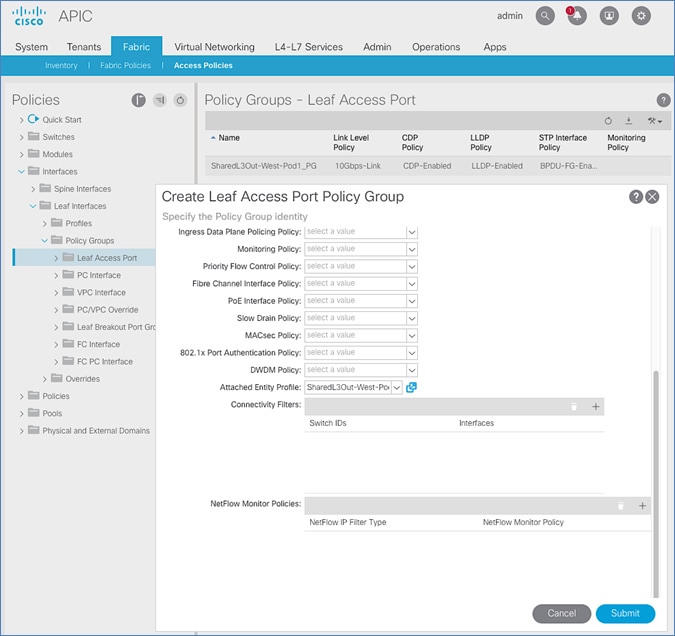
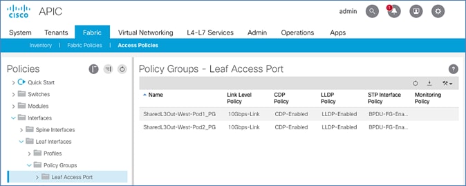
7. Click Submit to complete.
You should now see the policy groups for both Pods as shown below. In this case there are two Pods in the ACI Multipod environment.
Create Interface Profile for Interfaces to External Routed Domain
To create an interface profile to connect to external gateways outside the ACI fabric, follow these steps:
1. Use a browser to navigate to the APIC GUI. Log in using the admin account.
2. From the top navigation menu, select Fabric > Access Policies.
3. From the left navigation menu, expand and select Interfaces > Leaf Interfaces > Profiles.
4. Right-click and select Create Leaf Interface Profile.
5. In the Create Leaf Interface Profile pop-up window, specify a Name. For Interface Selectors, click the [+] to select access ports to apply interface policies to. In this case, the interfaces are access ports that connect Border Leaf switches to gateways outside ACI.
6. In the Create Access Port Selector pop-up window, specify a selector Name. For the Interface IDs, specify the access ports connecting to the two external gateways. For the Interface Policy Group, select the previously created Policy Group from the drop-down list.
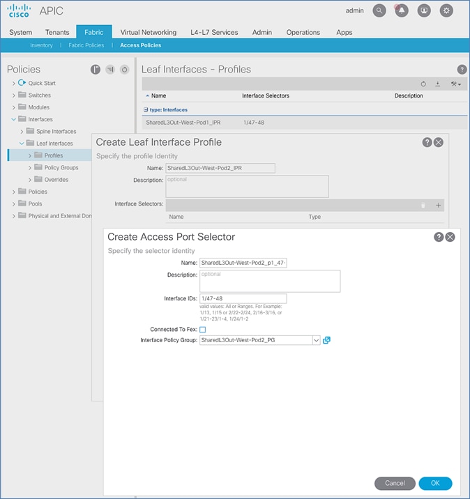
7. Click OK to complete and close the Create Access Port Selector pop-up window.
8. Click Submit to complete and close the Create Leaf Interface Profile pop-up window.
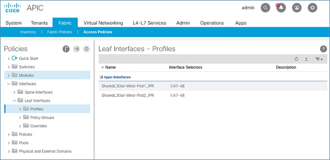
9. You should now see the Interface profiles for both Pods as shown below.
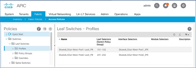
Create Leaf Switch Profile to External Routed Domain
To create a leaf switch profile to configure connectivity to external gateway routers outside the ACI fabric, follow these steps:
1. Use a browser to navigate to the APIC GUI. Log in using the admin account.
2. From the top navigation menu, select Fabric > Access Policies.
3. From the left navigation menu, expand and select Switches > Leaf Switches > Profiles.
4. Right-click and select Create Leaf Profile.
5. In the Create Leaf Profile pop-up window, specify a profile Name. For Leaf Selectors, click the [+] to select the Leaf switches to apply the policies to. In this case, the Leaf switches are the Border Leaf switches that connect to the gateways outside ACI.
6. Specify a Leaf Selector Name. For the Interface IDs, specify the access ports connecting to the two external gateways. For Blocks, select the Node IDs of the Border Leaf switches from the drop-down list. Click Update.
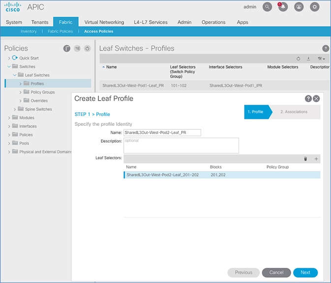
7. Click Next.
8. In the Associations window, select the previously created Interface Selector Profiles from the list.
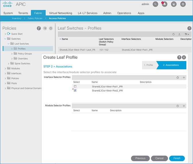
9. Click Finish to complete.
10. You should now see the profiles for both Pods as shown below.
Configure Tenant Networking for Shared L3Out
Pod-2 uses the same Tenant, VRF and Bridge Domain as Pod-1 for Shared L3Out. To configure tenant networking, follow these steps:
1. Use a browser to navigate to the APIC GUI. Log in using the admin account.
2. From the top navigation menu, select Tenants > common.
3. From the left navigation pane, select and expand Tenant common > Networking > VRFs.
4. Right-click and select Create VRF.
5. In the Create VRF pop-up window, STEP 1 > VRF, specify a Name (for example, common-SharedL3Out_VRF).
6. Check the box for Create a Bridge Domain.

7. Click Next.
8. In the Create VRF pop-up window, STEP 2 > Bridge Domain, specify a Name (for example, common-SharedL3Out_BD).
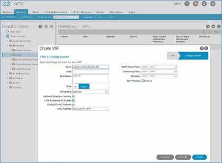
9. Click Finish to complete.
Table 13 Tenant Networking for Shared L3Out
Configure External Routed Networks under Tenant Common
Table 14 Routed Outside – Pod-1
To specify the domain type to connect to external gateway routers outside the ACI fabric, follow these steps:
1. Use a browser to navigate to the APIC GUI. Log in using the admin account.
2. From the top navigation menu, select Tenants > common.
3. In the left navigation pane, select and expand Tenant common > Networking > External Routed Networks.
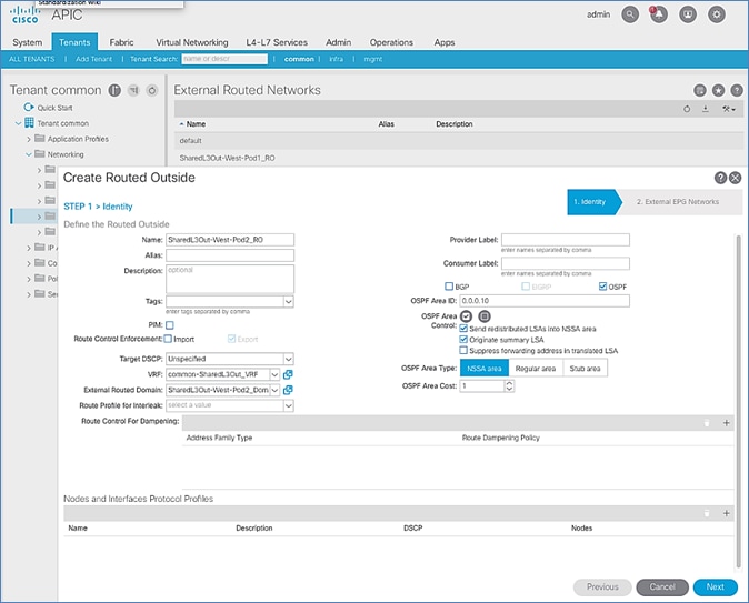
4. Right-click and select Create Routed Outside.
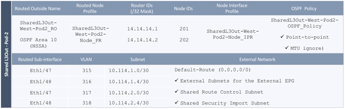
5. In the Create Routed Outside pop-up window, specify a Name (for example, SharedL3Out-West-Pod2_RO). Select the check box next to OSPF. For the OSPF Area ID, enter 0.0.0.10 (should match the external gateway configuration). For the VRF, select the previously created VRF from the drop-down list. For the External Routed Domain, select the previously created domain from the drop-down list. For Nodes and Interfaces Protocol Profiles, click [+] to add a Node Profile.
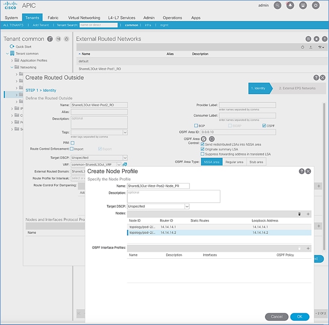
6. In the Create Node Profile pop-up window, specify a profile Name (for example, SharedL3Out-West-Pod2-Node_PR). For Nodes, click [+] to add a Node.
7. In the Select Node pop-up window, for the Node ID, select first Border Leaf switch from the drop-down list. For the Router ID, specify the router ID for the first Border Leaf Switch (for example, 14.14.14.1). Click OK to complete selecting the Node. Repeat to add the second Border Leaf to the list of Nodes. For OSPF Interface Profiles, click [+] to add a profile.
8. In the Create Interface Profile pop-up window, for Step 1 > Identity, specify a Name (for example, SharedL3Out-West-Pod2-Node_IPR). Click Next. In Step 2 > Protocol Profiles, for the OSPF Policy, use the drop-down list to select Create OSPF Interface Policy.
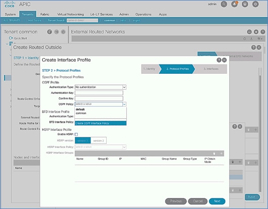
9. In the Create OSPF Interface Policy pop-up window, specify a Name (for example, SharedL3Out-West-Pod2-OSPF_Policy). For Network Type, select Point-to-Point. For Interface Controls, select the checkbox for MTU ignore.
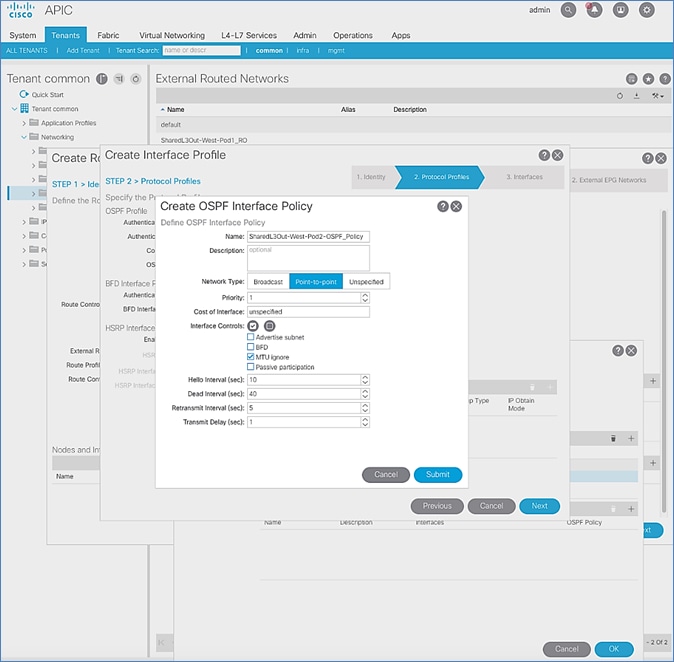
10. Click Submit to complete creating the OSPF policy.
11. In the Create Interface Profile pop-up window, for the OSPF Policy, the newly created policy should now show up as the policy.
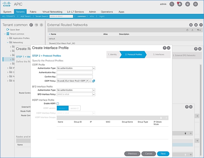
12. Click Next.
13. For STEP 3 > Interfaces, select the tab for Routed Sub-Interface. Click [+] on the right side of the window to add a routed sub-interface.
14. In the Select Routed Sub-Interface pop-up window, for Node, select the first Border Leaf. For Path, select the interface (for example, 1/47) on the first Border Leaf that connects to the first external gateway. For Encap, specify the VLAN (for example, 315). For IPv4 Primary / IPv6 Preferred Address, specify the address (for example, 10.114.1.1/30).
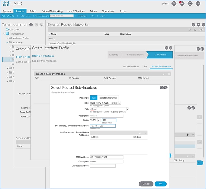
15. Click OK to complete configuring the first routed sub-interface.
16. In STEP 3 > Interfaces, under Routed Sub-Interface tab, click [+] again to create the next sub-interface that connects the first Border Leaf to the second Gateway.
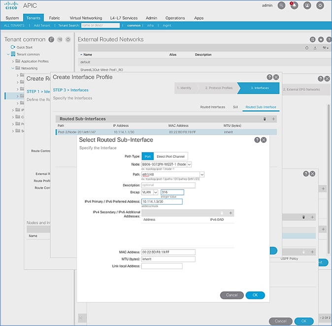
17. Click OK to complete configuring the first routed sub-interface.
18. Repeat steps 1-17 to create two more sub-interfaces on the second Border Leaf switch to connect to the two external gateways.
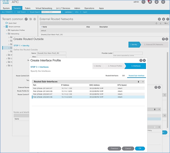
19. Click OK to complete the Interface Profile configuration and to close the Create Interface Profile pop-up window.
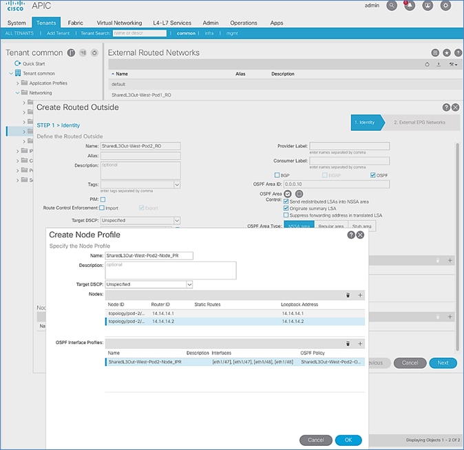
20. Click OK to complete the Node Profile configuration and to close the Create Node Profile pop-up window.
21. In the Create Routed Outside pop-up window, click Next. In STEP 2 > External EPG Networks, for External EPG Networks, click [+] to add an external network.
22. In the Created External Network pop-up window, specify a Name (for example, Default-Route). For Subnet, click [+] to add a Subnet.
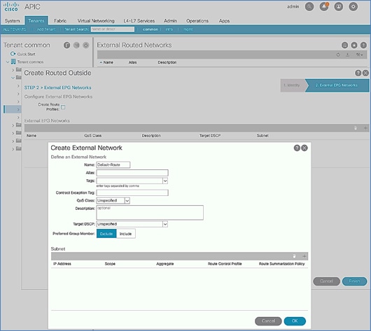
23. In the Create Subnet pop-up window, for the IP Address, enter a route (for example, 0.0.0.0/0). Select the checkboxes for External Subnets for the External EPG, Shared Route Control Subnet, and Shared Security Import Subnet.
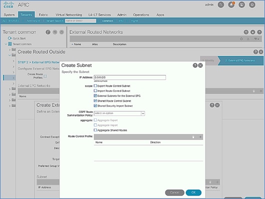
24. Click OK to complete creating the subnet and close the Create Subnet pop-up window.
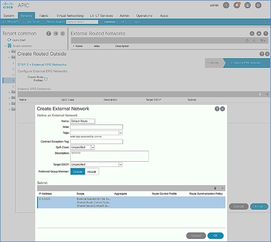
25. Click OK again to complete creating the external network and close the Create External Network pop-up window.
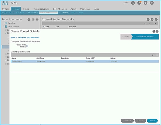
26. Click Finish to complete creating the Routed Outside.
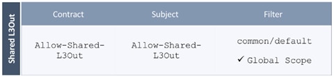
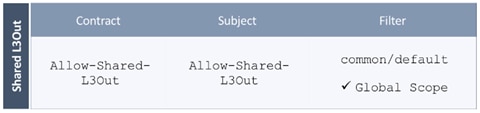
Create Contracts for External Routed Networks from Tenant (common)
Table 15 Contracts for External Routed Networks
To create contracts for external routed networks from Tenant common, follow these steps:
1. Use a browser to navigate to the APIC GUI. Log in using the admin account.
2. From the top navigation menu, select Tenants > common.
3. In the left navigation pane, select and expand Tenant common > Contracts.
4. Right-click Contracts and select Create Contract.
5. In the Create Contract pop-up window, specify a Name (for example, Allow-Shared-L3Out).
6. For Scope, select Global from the drop-down list to allow the contract to be consumed by all tenants.
7. For Subjects, click [+] on the right side to add a contract subject.
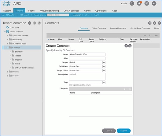
8. In the Create Contract Subject pop-up window, specify a Name (for example, Allow-Shared-L3Out).
9. For Filters, click [+] on the right side to add a filter.
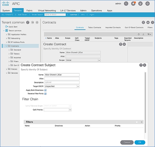
10. In the Filters section of the window, for Name, select default (common) from the drop-down list to create a default filter for Tenant common.
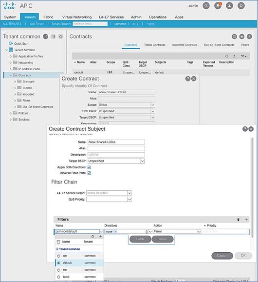
11. Click Update.
12. Click OK to complete creating the contract subject.
13. Click Submit to complete creating the contract.
Provide Contracts for External Routed Networks from Tenant (common)
Table 16 Contracts for External Routed Networks
To provide contracts for external routed networks from Tenant common, follow these steps:
1. Use a browser to navigate to the APIC GUI. Log in using the admin account.
2. From the top navigation menu, select Tenants > common.
3. In the left navigation pane, select and expand Tenant common > Networking > External Routed Networks.
4. Select and expand the recently created External Routed Network for SharedL3out or Routed Outside network (for example, SharedL3Out-West-Pod1_RO).
5. Select and expand Networks.
6. Select the recently created route (for example, Default-Route).
7. In the right windowpane, select the tab for Policy and then Contracts.
8. Under the Provided Contracts tab, click [+] on the right to add a Provided Contract.
9. For Name, select the previously created contract (for example, common/Allow-Shared-L3Out) from the drop-down list.
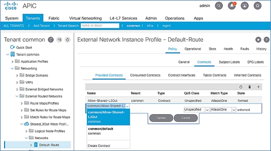
10. Click Update.
11. Other Tenants can now ‘consume’ the Allow-Shared-L3Out contract to route traffic outside the ACI fabric. This deployment example shows a default filter to allow all traffic. More restrictive contracts can be created for a more restrictive access to destinations outside the fabric.
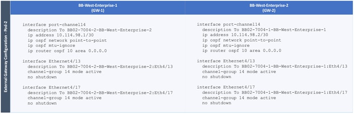
Configure External Gateways in the Outside Network
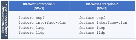
This section provides a sample configuration from the Nexus switches that serve as external Layer 3 Gateways for Pod-2. The gateways are in the external network and peer with ACI border leaf switches in Pod-2 using OSPF. The gateway configuration shown below shows only the relevant portion of the configuration – it is not the complete configuration.
Enable Protocols
The protocols used between the ACI border leaf switches and external gateways have to be explicitly enabled on Nexus platforms used as external gateways in this design. The configuration to enable these protocols are provided below.
Table 17 External Gateways for Pod-2 – Protocols
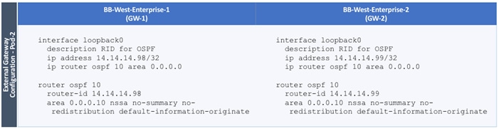
Configure OSPF
OSPF is used between the external gateways and ACI border leaf switches to exchange routing between the two domains. The global configuration for OSPF is provided below. Loopback is used as the router IDs for OSPF. Note that interfaces between ACI border leaf switches will be in OSPF Area 10.
Table 18 External Gateways for Pod-2 – Protocols
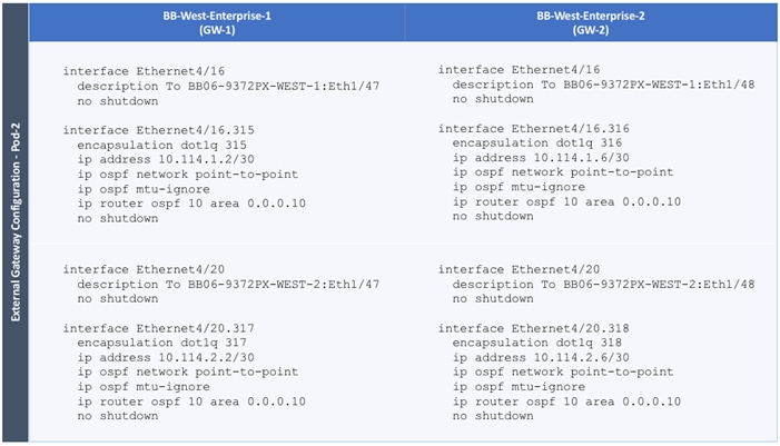
Configure Interfaces
The interface level configuration for connectivity between external gateways and ACI border leaf switches is provided below. Note that interfaces between ACI border leaf switches are in OSPF Area 10 while the loopbacks and port-channel links between the gateways are in OSPF Area 0.
Table 19 Interface Configuration – To ACI Border Leaf Switches
The configuration on the port-channel with 2x10GbE links that provide direct connectivity between the external gateways is provided below.
Table 20 Interface Configuration – Between External Gateways
Deploy VSV-Foundation Tenant
This section details the steps for creating the VSV-Foundation Tenant in the ACI Fabric. This tenant will host infrastructure connectivity for the compute (VMware ESXi on UCS nodes) and the storage (IBM FS9100) environments, as well as Shared Infrastructure (AD/DNS).
The following ACI constructs are defined in the VSV-Foundation Tenant configuration for the iSCSI-based storage access:
· Tenant: VSV-Foundation
· VRF: VSV-Foundation_VRF
· Application Profile VSV-Host-Conn-AP consist of three EPGs:
- VSV-iSCSI-A_EPG statically maps the VLANs associated with iSCSI-A interfaces on the IBM storage controllers and Cisco UCS Fabric Interconnects (VLAN 3161)
§ Bridge Domain: VSV-iSCSI-A_BD
- VSV-iSCSI-B_EPG statically maps the VLANs associated with iSCSI-B interfaces on the IBM storage controllers and Cisco UCS Fabric Interconnects (VLAN 3162)
§ Bridge Domain: VSV-iSCSI-B_BD
- VSV-vMotion_EPG statically maps vMotion VLAN (3173) on the Cisco UCS Fabric Interconnects
§ Bridge Domain: VSV-vMotion_BD
· Application Profile VSV-IB-MGMT_AP consist of one EPG:
- VSV-IB-MGMT_EPG statically maps the management VLAN (11) on the Cisco UCS Fabric Interconnects. This EPG is configured to provide VMs and ESXi hosts access to the existing management network via Shared L3Out connectivity. This EPG utilizes the bridge domain VSV-IB-Mgmt_BD.
To create a tenant, follow these steps:
1. In the APIC GUI, select Tenants -> Add Tenant.
2. Name the Tenant VSV-Foundation.
3. For the VRF Name, enter VSV-Foundation. Keep the check box “Take me to this tenant when I click finish” checked.

4. Click Submit to finish creating the Tenant.
Create Bridge Domains
The following Bridge Domains and EPGs will be created to be associated with the EPGs:
| Bridge Domain |
EPG |
VLAN |
Gateway (subnet/mask) |
| VSV-IB-Mgmt_BD |
VSV-IB-MGMT_EPG |
11 |
10.1.160.254/22 |
| VSV-iSCSI-A_BD |
VSV-iSCSI-A_EPG |
3161 |
|
| VSV-iSCSI-B_BD |
VSV-iSCSI-B_EPG |
3162 |
|
| VSV-vMotion_BD |
VSV-vMotion_EPG |
3173 |
|
To create a Bridge Domain, follow these steps:
1. In the left pane, expand Tenant VSV-Foundation and Networking.
2. Right-click Bridge Domains and select Create Bridge Domain.
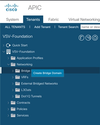
3. Name the Bridge Domain VSV-IB-MGMT-BD.
4. Select VSV-Foundation from the VRF drop-down list.
5. Select Custom under Forwarding and enable Flood for L2 Unknown Unicast.

6. Click Next.
7. Under L3 Configurations, make sure Limit IP Learning to Subnet is selected and select EP Move Detection Mode – GARP based detection.
8. Select the + option to the far right of Subnets.
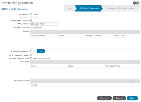
9. Provide the appropriate Gateway IP and mask for the subnet.
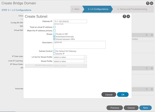
10. Select the Scope options for Advertised Externally and Shared between VRFs.
11. Click OK.
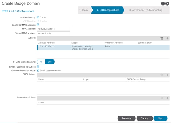
12. Select Next.
13. No changes are needed for Advanced/Troubleshooting. Click Finish to finish creating the Bridge Domain.
14. Repeat these steps for the [VSV-iSCSI-A_BD, VSV-iSCSI-B_BD, and VSV-vMotion_BD] bridge domain creations, leaving out the Subnet creation for the bridge domains.
15. Create a bridge domain for iSCSI-A path as shown below.

16. Create a bridge domain for iSCSI-B path as shown below.
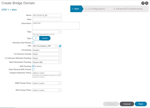
17. Create a bridge domain for vMotion as shown below.
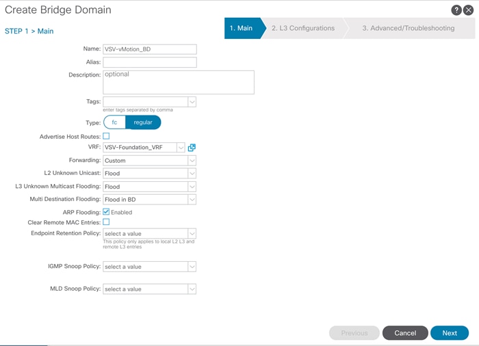
Create Application Profile for In-Band Management
To create an application profile for In-Band Management, follow these steps:
1. In the left pane, expand tenant VSV-Foundation, right-click Application Profiles and select Create Application Profile.
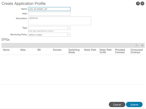
2. Name the Application Profile VSV-IB-MGMT_AP and click Submit to complete adding the Application Profile.
Create EPG for In-Band Management and Associate with Bridge Domain
This EPG will be used to access common resources such as AD and DNS etc., as well as the In-Band Mgmt. network for ESXi management.
To create the EPG for In-Band Management, follow these steps:
1. In the left pane, expand the Application Profiles and right-click the VSV-IB-MGMT_AP Application Profile and select Create Application EPG.
2. Name the EPG VSV-IB-MGMT_EPG.
3. From the Bridge Domain drop-down list, select Bridge Domain VSV-IB-MGMT_BD.
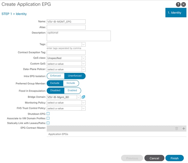
4. Click Finish to complete creating the EPG.
Associate EPG with UCS Domain
To associate the In-Band Management EPG with UCS Domain, follow these steps:
1. In the left menu, expand the newly created EPG, right-click Domains and select Add L2 External Domain Association.
2. Select the VSV-UCS_Domain L2 External Domain Profile.
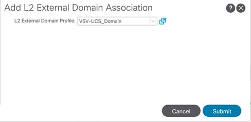
3. Click Submit.
Create Static EPG and VLAN Binding on vPC Interfaces to UCS Domain
To statically bind the In-Band Management EPG and VLANs to vPC interfaces going to the UCS Domain, follow these steps:
1. In the left menu, navigate to VSV-IB-MGMT_EPG > Static Ports.
2. Right-click Static Ports and select Deploy Static EPG on PC, VPC, or Interface.
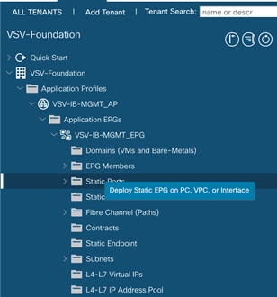
3. Select the Virtual Port Channel Path Type, then for Path select the vPC for the first UCS Fabric Interconnect.
4. For Port Encap leave VLAN selected and fill in the UCS In-Band management VLAN ID <11>.

5. Set the Deployment Immediacy to Immediate and click Submit.
6. Repeat steps 1-5 to add the Static Port mapping for the second UCS Fabric Interconnect vPC.
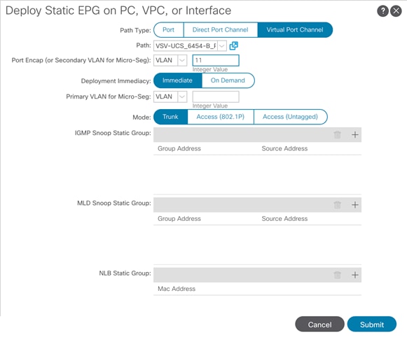
Create Contract to Access Outside Networks via Shared L3Out
To create a contract to access Shared L3Out in the common Tenant, follow these steps:
1. In the left navigation pane for the VSV-IB-MGMT_EPG, right-click Contracts, and select add Consumed Contract.
2. In the Add Consumed Contract pop-up window, select the Allow-Shared-L3Out contract from the drop-down list.
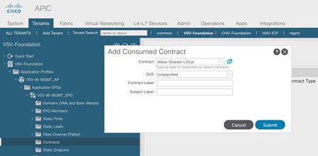
3. Click Submit.
Create Application Profile for Host Connectivity
The Foundation tenant will also contain EPGs for hypervisor specific traffic that will be grouped into their own Application Profiles. These EPGs are for the ESXi iSCSI VMkernel ports for non-routed iSCSI traffic between the VMware ESXi hosts and IBM FS9100 storage and a vMotion EPG which will hold the non-routed vMotion traffic.
To create an application profile for Host-Connectivity, follow these steps:
1. In the left pane, expand tenant VSV-Host-Conn_AP, right-click Application Profiles and select Create Application Profile.
2. Name the Application Profile VSV-Host-Conn-AP and click Submit to complete adding the Application Profile.

Create EPG for vMotion
This EPG will connect the ESXi hosts for communicating vMotion traffic.
To create the EPG for vMotion, follow these steps:
1. In the left pane, expand the Application Profiles and right-click the VSV-Host-Conn_AP Application Profile and select Create Application EPG.
2. Name the EPG VSV-vMotion_EPG.
3. From the Bridge Domain drop-down list, select Bridge Domain VSV-vMotion_BD.

4. Click Finish to complete creating the EPG.
5. In the left menu, expand the newly created EPG, right-click Domains and select Add L2 External Domain Association.
6. Select the VSV-UCS_Domain L2 External Domain Profile.
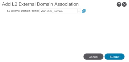
7. Click Submit.
8. In the left menu, right-click Static Ports and select Deploy Static EPG on PC, VPC, or Interface.
9. Select the Virtual Port Channel Path Type, then for Path select the vPC for the first UCS Fabric Interconnect.
10. For Port Encap leave VLAN selected and fill in the UCS vMotion VLAN ID <3173>.
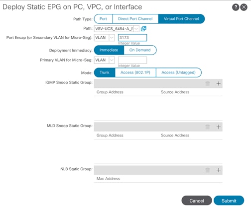
11. Set the Deployment Immediacy to Immediate and click Submit.
12. Repeat steps 8-11 to add the Static Port mapping for the second UCS Fabric Interconnect.

Create EPG for iSCSI
This EPG will connect the VMware ESXi hosts for communicating with IBM FS9100 storage Array.
To create the EPG for iSCSI EPGs, follow these steps:
1. In the left pane, expand the Application Profiles and right-click the VSV-Host-Conn_AP Application Profile and select Create Application EPG.
2. Name the EPG VSV-iSCSI-A_EPG.
3. From the Bridge Domain drop-down list, select Bridge Domain VSV-iSCSI-A_BD.
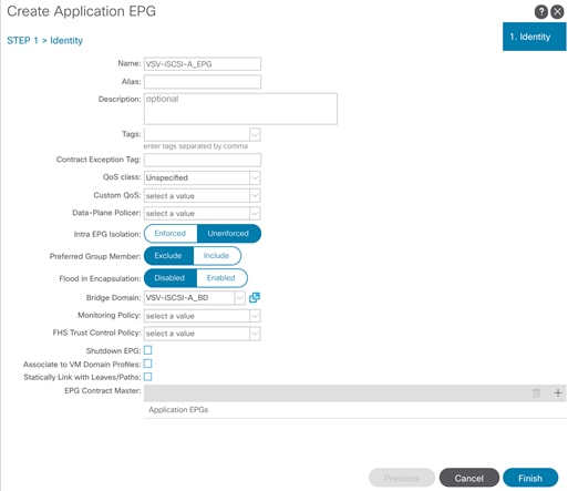
4. Click Finish to complete creating the EPG.
5. In the left menu, expand the newly created EPG, right-click Domains and select Add L2 External Domain and Physical Domain Associations.
6. Select the VSV-FS9100-A L2 Physical Domain Profile.
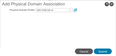
7. Right-click Domains again and select Add L2 External Domain and Physical Domain Associations.
8. Select the VSV-UCS_Domain L2 External Domain Profile.
9. Click Submit.
10. In the left menu, right-click Static Ports and select Deploy Static EPG on PC, VPC, or Interface.
11. Select the Virtual Port Channel Path Type, then for Path select the vPC for the first UCS Fabric Interconnect.
12. For Port Encap leave VLAN selected and fill in the UCS vMotion VLAN ID <3161>.

13. Set the Deployment Immediacy to Immediate and click Submit.
14. Repeat steps 10-13 to add the Static Port mapping for the second UCS Fabric Interconnect.
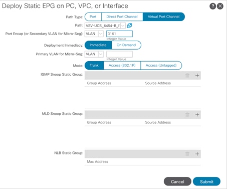
15. In the left menu, right-click Static Ports and select Deploy Static EPG on PC, VPC, or Interface.
16. Select the Port Path Type, then for Path select the path for the first port on leaf switch A.
17. For Port Encap leave VLAN selected and fill in the UCS iSCSI-A VLAN ID <3161>.
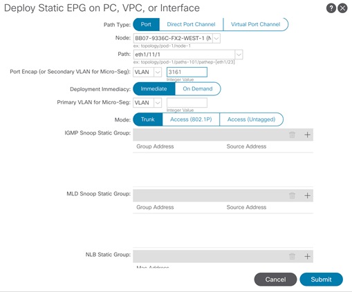
18. Set the Deployment Immediacy to Immediate and click Submit.
19. Repeat steps 15-18 to add the Static Port mapping for the second port on leaf switch A.
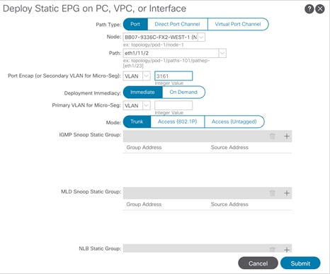
20. In the left pane, expand the Application Profiles and right-click the VSV-Host-Conn_AP Application Profile and select Create Application EPG.
21. Name the EPG VSV-iSCSI-B_EPG.
22. From the Bridge Domain drop-down list, select Bridge Domain VSV-iSCSI-B_BD.
23. Click Finish to complete creating the EPG.
24. In the left menu, expand the newly created EPG, right-click Domains and select Add L2 External Domain and Physical Domain Associations.
25. Select the VSV-FS9100-B L2 Physical Domain Profile.
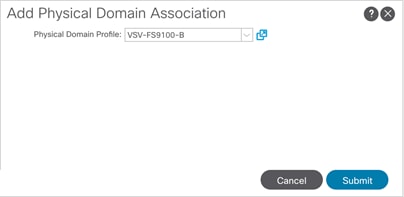
26. Right-click Domains again and select Add L2 External Domain and Physical Domain Associations.
27. Select the VSV-UCS_Domain L2 External Domain Profile.
28. Click Submit.
29. In the left menu, right-click Static Ports and select Deploy Static EPG on PC, VPC, or Interface.
30. Select the Virtual Port Channel Path Type, then for Path select the vPC for the first UCS Fabric Interconnect.
31. For Port Encap leave VLAN selected and fill in the UCS iSCSI-B VLAN ID <3162>.
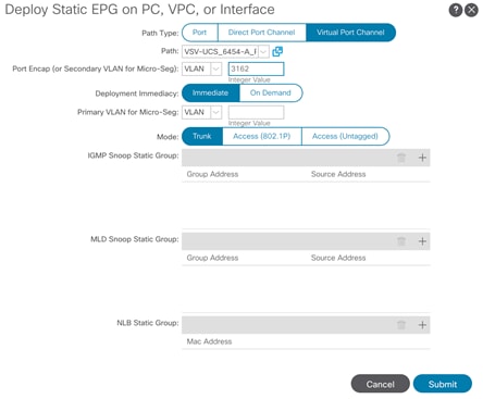
32. Set the Deployment Immediacy to Immediate and click Submit.
33. Repeat steps 27-32 to add the Static Port mapping for the second UCS Fabric Interconnect.
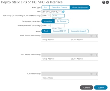
34. In the left menu, right-click Static Ports and select Deploy Static EPG on PC, VPC, or Interface.
35. Select the Port Path Type, then for Path select the path for the first port on leaf switch B.
36. For Port Encap leave VLAN selected and fill in the UCS iSCSI-B VLAN ID <3162>.

37. Set the Deployment Immediacy to Immediate and click Submit.
38. Repeat steps 33-37 to add the Static Port mapping for the second port on leaf switch B.
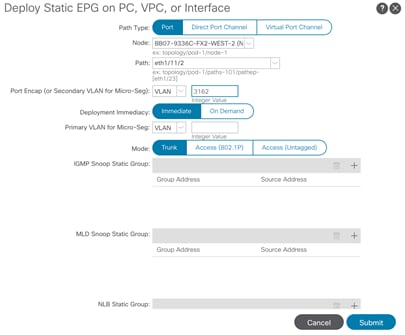
IBM FlashSystem 9100
![]() FlashSystem 9100 systems have specific connection requirements. Care must be taken to note the orientation of each node canister in the control enclosure.
FlashSystem 9100 systems have specific connection requirements. Care must be taken to note the orientation of each node canister in the control enclosure.
The FlashSystem 9100 control enclosure contains two node canisters. A label on the control enclosure identifies each node canister and power supply unit (PSU). As Figure 9 shows, node canister 1 is on top and node canister 2 is on the bottom. Because the node canisters are inverted, the location of the ports and the port numbering are oriented differently on each node canister. It is important to remember this orientation when installing adapters and cables.
Figure 9 Orientation of the Node Canisters and PSUs
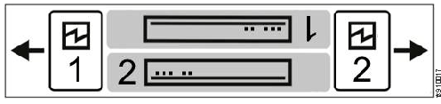
For example, Figure 10 shows the top node canister. On this canister, the PCIe slot and port numbering goes from right to left. PCIe adapter slot 1 contains a 4-port 16 Gbps Fibre Channel adapter, PCIe slot 2 contains a 2-port 25 Gbps iWARP Ethernet adapter, and PCIe slot 3 contains a 4-port 12 Gbps SAS adapter. The onboard Ethernet and USB ports are also shown.
Figure 10 Orientation of Ports on Node Canister 1
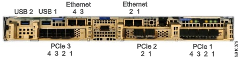
Figure 11 shows the bottom node canister. This node canister has the same type and number of adapters installed. However, on the bottom canister, the PCI slot and port numbering goes from left to right.
Figure 11 Orientation of Ports on Node Canister 2
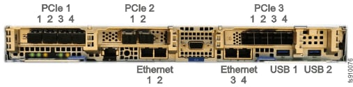
Four 10 Gb Ethernet ports on each node canister provide system management connections and iSCSI host connectivity. A separate technician port provides access to initialization and service assistant functions. Table 21 describes each port.
Table 21 Summary of Onboard Ethernet Ports
| On board Ethernet Port |
Speed |
Function |
| 1 |
10 Gbps |
Management IP, Service IP, Host I/O |
| 2 |
10 Gbps |
Secondary Management IP, Host I/O |
| 3 |
10 Gbps |
Host I/O |
| 4 |
10 Gbps |
Host I/O |
| T |
1 Gbps |
Technician Port - DHCP/DNS for direct attach service management |
The following connections are required for FlashSystem 9100 control enclosures:
· Each control enclosure requires two Ethernet cables to connect it to an Ethernet switch. One cable connects to port 1 of the top node canister, and the other cable connects to port 1 of the bottom node canister. For 10 Gbps ports, the minimum link speed is 1 Gbps. Both Internet Protocol Version 4 (IPv4) and Internet Protocol Version 6 (IPv6) are supported.
· To ensure system failover operations, Ethernet port 1 on each node canister must be connected to the same set of subnets. If used, Ethernet port 2 on each node canister must also be connected to the same set of subnets. However, the subnets for Ethernet port 1 do not have to be the same as Ethernet port 2.
· If you have more than one control enclosure in your system, the control enclosures communicate through their Fibre Channel ports.
· Each FlashSystem 9100 node canister also has three PCIe interface slots to support optional host interface adapters. The host interface adapters can be supported in any of the interface slots. Table 22 provides an overview of the host interface adapters.
· The 2-port SAS host interface adapter supports expansion enclosures. In total, FlashSystem 9100 control enclosures can have up to 20 chain-linked expansion enclosures, 10 per port.
Table 22 Summary of Supported Host Interface Adapters
| Protocol |
Feature |
Ports |
FRU part number |
Quantity supported |
| 16 Gbs Fibre Channel |
AHB3 |
4 |
01YM333 |
0-3 |
| 25 Gbs Ethernet (RoCE) |
AHB6 |
2 |
01YM283 |
0-3 |
| 25 Gbs Ethernet (iWARP) |
AHB7 |
2 |
01YM285 |
0-3 |
| 12 Gb SAS Expansion |
AHBA |
4, but only 2 are active for SAS expansion chains. |
01YM338 |
0-1 |
![]() Each node canister within the control enclosure (I/O group) must be configured with the same host interface adapters.
Each node canister within the control enclosure (I/O group) must be configured with the same host interface adapters.
Each node canister has four onboard 10 Gbps Ethernet ports which can be used for both host attachment or IP-based replication to another Spectrum Virtualize storage system.
Table 23 lists the fabric types that can be used for communicating between hosts, nodes, and RAID storage systems. These fabric types can be used at the same time.
| Communications type |
Host to node |
Node to storage system |
Node to node |
| Fibre Channel SAN |
Yes |
Yes |
Yes |
| iSCSI 10 Gbps Ethernet 25 Gbps Ethernet |
Yes |
Yes |
No |
| iSER 25 Gbps Ethernet |
Yes |
No |
No |
The feature codes for the 16 Gbps Fibre Channel adapter, 25Gbps iWarp adapter, and the 25Gbps RoCE adapter each include standard SFP transceivers for each adapter. In this design the 25Gbps RoCE adapter has been leveraged for iSCSI connectivity and the ports are connected to the Cisco Nexus 9336C-FX2 switches using breakout cables, SFP transceivers are not required with this connectivity.
The 2-port 25 GB Ethernet adapter for iWARP and the 2-port 25GB Ethernet adapter for RDMA over Converged Ethernet (RoCE) both support iSER host attachment. However, RoCE and iWARP are not cross-compatible; therefore, it is important to use the adapter that matches the iSER implementation on your SAN if iSER is planned to be implemented in the future.
![]() This document implements traditional iSCSI, iSER based iSCSI implementation can be configured with the support of iSER on Cisco VIC 1400 series when available with the future releases of Cisco UCS software.
This document implements traditional iSCSI, iSER based iSCSI implementation can be configured with the support of iSER on Cisco VIC 1400 series when available with the future releases of Cisco UCS software.
IBM Service Support Representative (SSR) Configuration
To install the FlashSystem 9100 hardware, an IBM SSR must complete the following tasks:
![]() You must complete the planning tasks and provide completed worksheets to the IBM SSR before they can proceed with installing and initializing your system.
You must complete the planning tasks and provide completed worksheets to the IBM SSR before they can proceed with installing and initializing your system.
· An IBM SSR unpacks and installs the AF7/AF8 control enclosures and any optional SAS expansion enclosures in the rack.
· Referring to the worksheets that you completed, the IBM SSR completes the cabling.
![]() If the IBM SSR is aware of your intent to add the FlashSystem 9100 to an existing system, the IBM SSR installs the FlashSystem 9100 control enclosure for you but does not initialize a system on it. If you are planning on adding a FlashSystem 9100 control enclosure to an existing Storwize® V7000 system, inform the IBM SSR of this intention. In these cases, the IBM SSR installs the FlashSystem 9100 control enclosure for you, but does not initialize a system on it, because the existing system is already initialized.
If the IBM SSR is aware of your intent to add the FlashSystem 9100 to an existing system, the IBM SSR installs the FlashSystem 9100 control enclosure for you but does not initialize a system on it. If you are planning on adding a FlashSystem 9100 control enclosure to an existing Storwize® V7000 system, inform the IBM SSR of this intention. In these cases, the IBM SSR installs the FlashSystem 9100 control enclosure for you, but does not initialize a system on it, because the existing system is already initialized.
After the hardware is installed, an IBM SSR connects a workstation to an AF7/AF8 control enclosure technician port and completes the following tasks:
· Configuring the system with a name, and management and service IP addresses.
· Logging in to the control enclosure using the management GUI, and completing the system setup wizard using information from the customer-supplied worksheets.
The SSR configuration steps are documented below.
Initialize the System
The initial configuration requires a workstation be locally attached to the Ethernet port labelled “T” on the Upper node canister in the FS9100 enclosure. “T” refers to Tech Port and will allocate an IP address to the connected workstation using DHCP and will redirect any DNS queries to the System Initialization page. This page shows the status of each node canister in the enclosure and will guide you through the initialization process.
To initialize the system, follow these steps:
1. Ensure both node canisters have been detected and click Proceed.
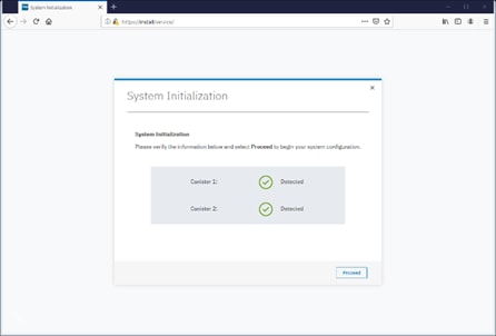
2. Click Next through the Welcome screen.
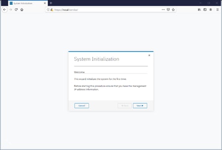
3. Select the option to define the enclosure as the first in a new system

4. Enter the network details for the management interface for the new system. This IP address is sometimes referred to as the Management IP, or Cluster IP and will be used to manage the FS9100 system via the web interface or CLI via SSH.
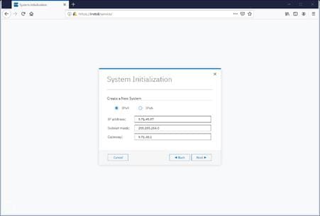
5. Acknowledge the Task Completion message.
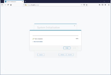
6. The initial configuration steps are now complete, and the system will now restart the Web Server.
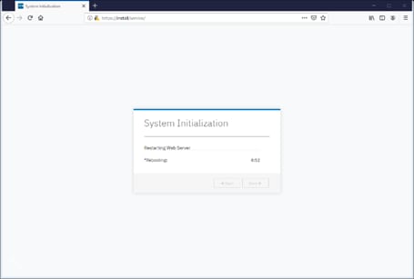
Prepare FS9100 for Customer Environments
Now the Management IP is enabled, all future configuration steps are made with this interface.
To prepare the FS9100 for customer environments, follow these steps:
1. Log in using the default credentials:
Username: superuser
Password: passw0rd
2. Click Next to proceed through the configuration wizard.
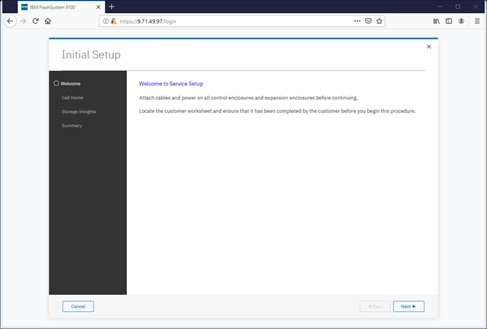
3. For optimal configuration, check the box to enable the Call Home feature.
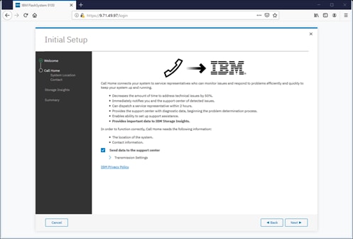
4. Detail the System Location.
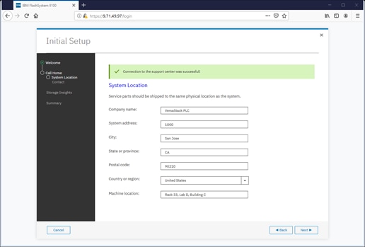
5. Specify the contact details.
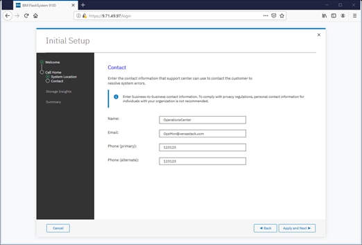
6. Specify the customer’s IBM ID and contact details.
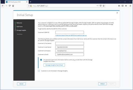
7. Click Next to finalize the IBM Storage Insights registration.
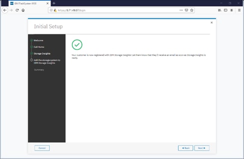
8. Review the Initial Setup summary and click Finish.
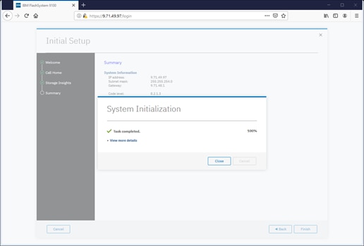
9. Click Close to complete the Service Initialization.
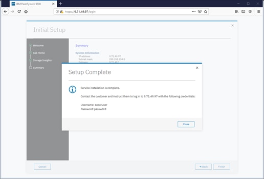
Customer Configuration Setup Tasks via the GUI
After completing the initial tasks above, launch the management GUI and continue configuring the IBM FlashSystem 9100.
To configure the customer’s tasks, follow these steps:
![]() Following the e-Learning module introduces the IBM FlashSystem 9100 management interface and provides an overview of the system setup tasks, including configuring the system, migrating and configuring storage, creating hosts, creating and mapping volumes, and configuring email notifications: Getting Started
Following the e-Learning module introduces the IBM FlashSystem 9100 management interface and provides an overview of the system setup tasks, including configuring the system, migrating and configuring storage, creating hosts, creating and mapping volumes, and configuring email notifications: Getting Started
1. Log into the management GUI using the cluster IP address configured above.

2. Log in using the default credentials:
Username: superuser
Password: passw0rd
3. Click Next to skip the Welcome message.
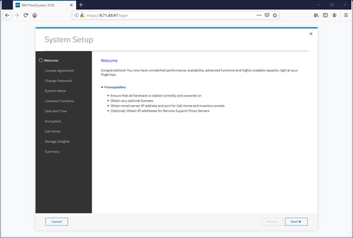
4. Read and accept the license agreement. Click Accept.
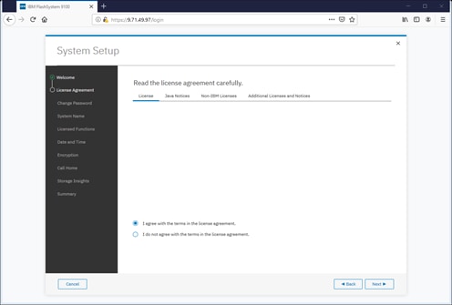
5. Define new credentials for the superuser user account.

6. Enter the System Name and click Apply and Next to proceed.
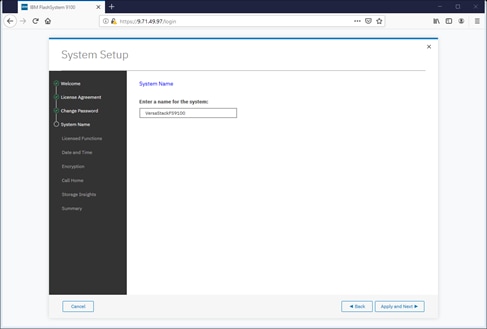
7. Enter the license details that was purchased for FlashCopy, Remote Mirroring, Easy Tier, and External Virtualization. Click Apply and Next to proceed.
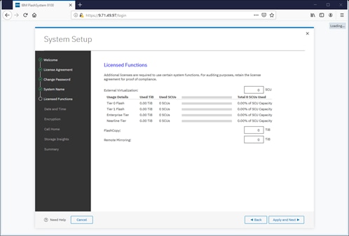
8. Configure the date and time settings, inputting NTP server details if available. Click Apply and Next to proceed.
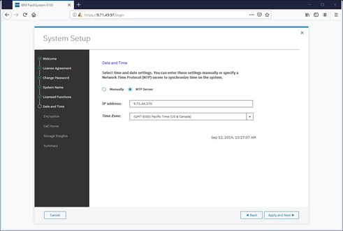
9. Enable the Encryption feature (or leave it disabled). Click Next to proceed.
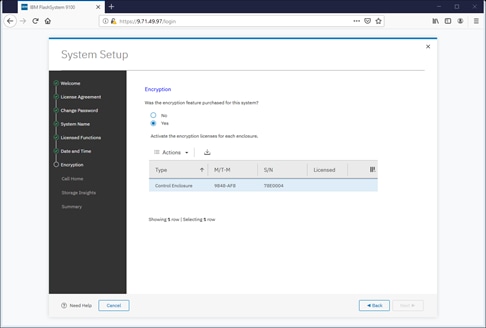
10. If using the encryption, select either Manual or Automatic activation and enter the authorization code or license key accordingly.
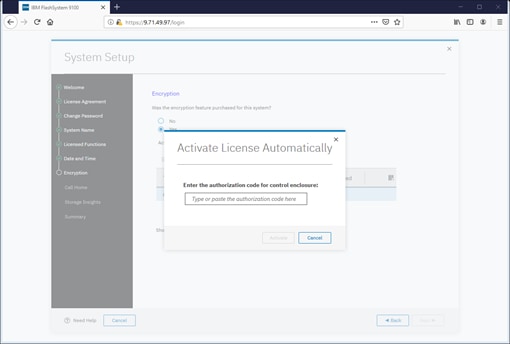
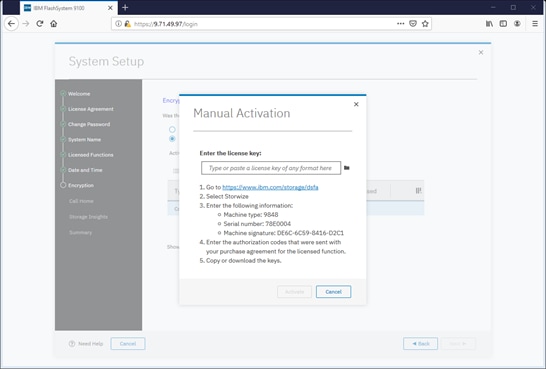
![]() It is highly recommended to configure email event notifications which will automatically notify IBM support centers when problems occur.
It is highly recommended to configure email event notifications which will automatically notify IBM support centers when problems occur.
11. Enter the complete company name and address and then click Next.
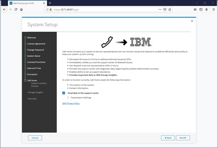
12. Enter the contact person for the support center calls. Click Apply and Next.
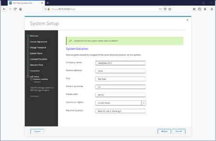
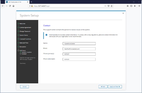
![]() IBM Storage Insights is required to enable performance/health monitoring required by remote IBM Support representatives when assisting with any support issues.
IBM Storage Insights is required to enable performance/health monitoring required by remote IBM Support representatives when assisting with any support issues.
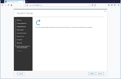
13. Review the final summary page and click Finish to complete the System Setup wizard.
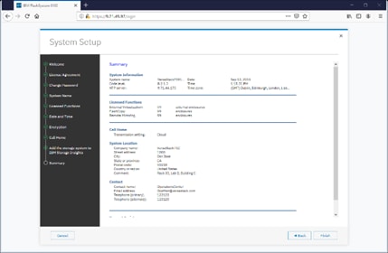
14. Setup Completed. Click Close.
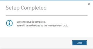
System Dashboard, and Post-Initialization Setup Tasks
To configure the necessary post-initialization setup tasks, follow these steps:
1. The System view of IBM FS9100 is now available, as shown below.
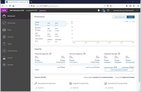
2. In the left side menu, hover over each of the icons on the Navigation Dock to become familiar with the options.
3. Verify the configured Management IP Address (Cluster IP) and configuring Service Assistant IP addresses for each node canister in the system.
4. On the Network screen, highlight the Management IP Addresses section. Then click the number 1 interface on the left-hand side to bring up the Ethernet port IP menu. If required, change the IP address if necessary and click OK.
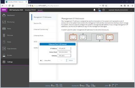
5. While still on the Network screen, select 1) Service IP Addresses from the list on the left and select each Node Canister Upper/Lower in turn, and change the IP address for port 1, click OK.
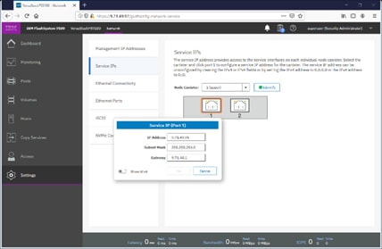
6. Repeat this process for port 1 on the other Node Canisters.
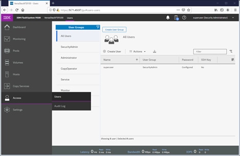
7. Click the Access icon from the Navigation Dock on the left and select Users to access the Users screen.
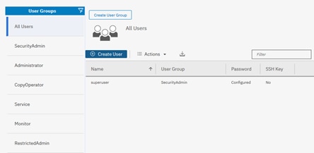
8. Select Create User.
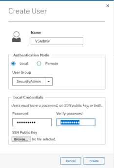
9. Enter a new name for an alternative admin account. Leave the SecurityAdmin default as the User Group, and input the new password, then click Create. Optionally, an SSH Public Key generated on a Unix server through the command “ssh-keygen -t rsa” can be copied to a public key file and associated with this user through the Choose File button.
![]() Consider using Remote Authentication (via LDAP) to centrally manage authentication, roles, and responsibilities. For more information on Remote Authentication, refer to Redbook: Implementing the IBM System Storage SAN Volume Controller with IBM Spectrum Virtualize V8.2.1.
Consider using Remote Authentication (via LDAP) to centrally manage authentication, roles, and responsibilities. For more information on Remote Authentication, refer to Redbook: Implementing the IBM System Storage SAN Volume Controller with IBM Spectrum Virtualize V8.2.1.
Create Storage Pools and Allocate Storage
Typically, the NVMe drives within the FlashSystem 9100 enclosure are grouped together into a Distributed RAID array (sometimes referred to as a Managed Disk or mdisk), and are added to a storage resource called a Storage Pool (sometimes referred to as Managed Disk Group or mdiskgrp. Volumes are then created within this storage pool and presented to the host(s) within the UCS chassis. Data from a UCS host is striped across multiple drives for performance, efficiency and redundancy.
Data Reduction Pools, SCSI UNMAP, and Data Deduplication
If enabling Data reduction on the pool during creation, the pool will be created as a Data Reduction Pool (DRP). Data Reduction Pools are a new type of storage pool, implementing techniques such as thin-provisioning, compression, and deduplication to reduce the amount of physical capacity required to store data.
When using modern operating systems that support SCSI UNMAP, the storage pool also enables the automatic de-allocation and reclaim capacity occupied by deleted data and, for the first time, enable this reclaimed capacity to be reused by other volumes in the pool.
Data deduplication is one of the methods of reducing storage needs by eliminating redundant copies of data. Existing or new data is categorized into chunks that are examined for redundancy. If duplicate chunks are detected, then pointers are shifted to reference a single copy of the chunk, and the duplicate data sets are then released.
Deduplication has several benefits, such as storing more data per physical storage system, saving energy by using fewer disk drives, and decreasing the amount of data that must be sent across a network to another storage for backup replication and for disaster recovery.
However, these data savings come at a cost. There is a performance overhead when using DRPs when compared to traditional storage pools. And a percentage of the capacity of a DRP is reserved for system usage. For more information on Data Reduction Pools and techniques, refer to the Redbook publication: Implementing the IBM System Storage SAN Volume Controller.
1. Select Pools from the Navigation Dock and select MDisk by Pools.
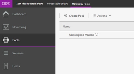
2. Click Create Pool, and enter the name of the new storage pool. Click Create.
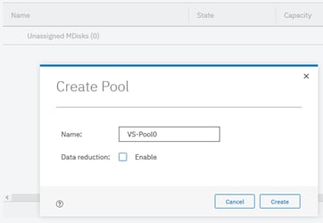
3. Identify the available drives along the bottom of the window

4. Right-click the new Pool and select Add Storage.
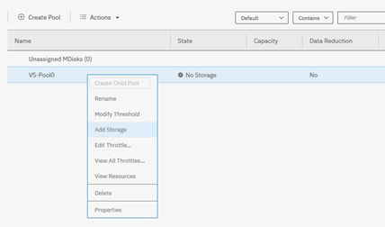
5. Select Internal to utilize drives within the enclosure, rather than from externally virtualized storage controllers.
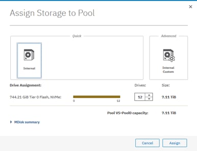
6. The Managed Disk (mdisk) has now been created and allocated to the storage pool.
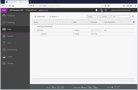
7. Reference the Running Tasks window to monitor the array initialization.
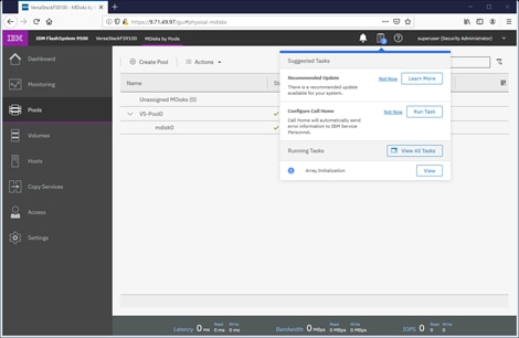
![]() During the initialization, the array performance will be sub-optimal. Where possible, wait for the array initialization to complete before running resource intensive workloads.
During the initialization, the array performance will be sub-optimal. Where possible, wait for the array initialization to complete before running resource intensive workloads.
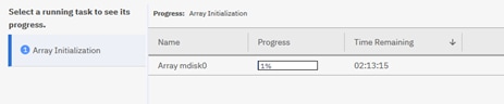
8. Select Internal, review the drive assignments and then select Assign.
![]() Depending on customer configuration and requirements, select Internal Custom to manually create tired storage pools by creating arrays formed by different drive technologies, such as Flash Core Modules (FCM), Solid state disks (SSD). To optimize storage performance, Spectrum Virtualize uses Artificial Intelligence to balance data between all arrays within the storage pool ensuring frequently accessed data is stored on the fastest performing media, while data which is accessed infrequently will be moved to slower, cheaper media.
Depending on customer configuration and requirements, select Internal Custom to manually create tired storage pools by creating arrays formed by different drive technologies, such as Flash Core Modules (FCM), Solid state disks (SSD). To optimize storage performance, Spectrum Virtualize uses Artificial Intelligence to balance data between all arrays within the storage pool ensuring frequently accessed data is stored on the fastest performing media, while data which is accessed infrequently will be moved to slower, cheaper media.
9. Validate the pools are online and have the relevant storage assigned.
10. Select Volumes from the Navigation Dock and then select Volumes.
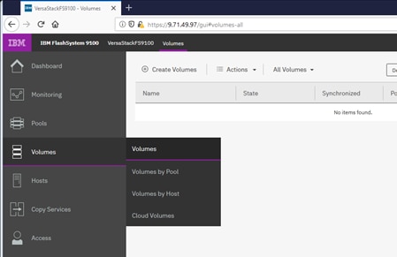
11. Click Create Volumes.
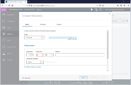
12. Define the volume characteristics, paying attention to any capacity saving, and/or high availability requirements, and specify a friendly name. Click Create.
13. Validate the created volumes.
![]() Creating volumes will be explained in following sections of this document
Creating volumes will be explained in following sections of this document
IBM FS9100 iSCSI Configuration
![]() Cisco UCS configuration requires information about the iSCSI IQNs on IBM FS9100. Therefore, as part of the initial storage configuration, iSCSI ports are configured on IBM FS9100
Cisco UCS configuration requires information about the iSCSI IQNs on IBM FS9100. Therefore, as part of the initial storage configuration, iSCSI ports are configured on IBM FS9100
Two 25G ports from each of the IBM FS9100 node canisters are connected to each of Nexus 9336C-FX2 switches. These ports are configured as shown in Table 24 .
Table 24 IBM FS9100 iSCSI Interface Configuration
| System |
Port |
Path |
VLAN |
IP address |
| Node canister 1 |
5 |
iSCSI-A |
3161 |
10.29.161.249/24 |
| Node canister 1 |
6 |
iSCSI-B |
3162 |
10.29.162.249/24 |
| Node canister 2 |
5 |
iSCSI-A |
3161 |
10.29.161.250/24 |
| Node canister 2 |
6 |
iSCSI-B |
3162 |
10.29.162.250/24 |
To configure the IBM FS9100 system for iSCSI storage access, follow these steps:
1. Log into the IBM Management Interface GUI and navigate to Settings > Network.
2. Click the iSCSI icon and enter the system and node names as shown:
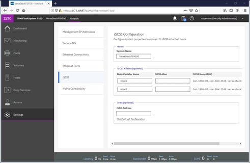
3. Note the resulting iSCSI Name (IQN) in the Table 25 to be used later in the configuration procedure.
| Node |
Example iSCSI name (IQN) |
| Node 1 |
iqn.1986-03.com.ibm:2145.versastack-fs9100.node1 |
| Node 2 |
iqn.1986-03.com.ibm:2145.versastack-fs9100.node2 |
4. Click the Ethernet Ports icon.
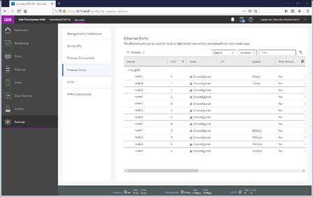
5. Click Actions and choose Modify iSCSI Hosts.
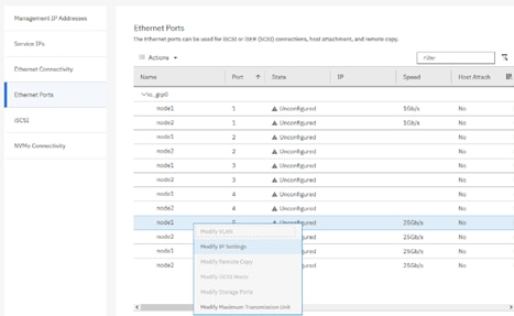
6. Make sure IPv4 iSCSI hosts field is set to enable – if not, change the setting to Enabled and click Modify.
7. If already set, click Cancel to close the configuration box.
8. For each of the four ports listed in Table 24 , repeat steps 1-7.
9. Right-click the appropriate port and choose Modify IP Settings.
10. Enter the IP address, Subnet Mask and Gateway information in Table 24
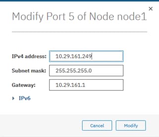
11. Click Modify.
12. Right-click the newly updated port and choose Modify VLAN.
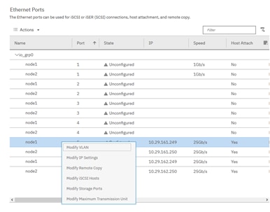
13. Check the box to Enable VLAN.
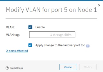
14. Enter the appropriate VLAN from Table 24 .
![]() This is only needed if the VLAN is not set as native VLAN in the UCS, do not enable VLAN if the iSCSI VLAN is set as native VLAN.
This is only needed if the VLAN is not set as native VLAN in the UCS, do not enable VLAN if the iSCSI VLAN is set as native VLAN.
15. Keep the Apply change to the failover port too check box checked.
16. Click Modify.
17. Repeat steps 1-16 for all for iSCSI ports listed in Table 24 .
18. Verify all ports are configured as shown below. The output below shows configuration for two FS9100 node canisters.
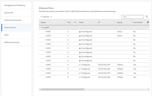
Modify Interface MTU
Use the cfgportip CLI command to set Jumbo Frames (MTU 9000). The default value of port MTU is 1500. An MTU of 9000 (jumbo frames) provides improved CPU utilization and increased efficiency by reducing the overhead and increasing the size of the payload.
To modify the interface MTU, follow these steps:
1. The MTU configuration can be verified using the command:
svcinfo lsportip <port number> | grep mtu
2. SSH to the IBM FS9100 management IP address and use following CLI command to set the MTU for ports 5 and 6 in the FS9100 in iogrp 0:
svctask cfgportip -mtu 9000 -iogrp 0 5
svctask cfgportip -mtu 9000 -iogrp 0 6
This completes the initial configuration of the IBM systems. The next section explains the Cisco UCS configuration.
This VersaStack deployment describes the configuration steps for the Cisco UCS 6454 Fabric Interconnects (FI) in a design that will support iSCSI boot to the IBM FS9100 through the Cisco ACI Fabric.
Cisco UCS Initial Configuration
This section provides detailed procedures for configuring the Cisco Unified Computing System (Cisco UCS) for use in a VersaStack environment. The steps are necessary to provision the Cisco UCS C-Series and B-Series servers and should be followed precisely to avoid configuration errors.
Cisco UCS 6454 A
To configure the Cisco UCS for use in a VersaStack environment, follow these steps:
1. Connect to the console port on the first Cisco UCS 6454 fabric interconnect.
Enter the configuration method. (console/gui) ? console
Enter the setup mode; setup newly or restore from backup.(setup/restore)? setup
You have chosen to setup a new Fabric interconnect? Continue? (y/n): y
Enforce strong password? (y/n) [y]: y
Enter the password for "admin": <password>
Confirm the password for "admin": <password>
Is this Fabric interconnect part of a cluster(select no for standalone)? (yes/no) [n]: yes
Which switch fabric (A/B)[]: A
Enter the system name: <Name of the System>
Physical Switch Mgmt0 IP address: <Mgmt. IP address for Fabric A>
Physical Switch Mgmt0 IPv4 netmask: <Mgmt. IP Subnet Mask>
IPv4 address of the default gateway: <Default GW for the Mgmt. IP >
Cluster IPv4 address: <Cluster Mgmt. IP address>
Configure the DNS Server IP address? (yes/no) [n]: y
DNS IP address: <DNS IP address>
Configure the default domain name? (yes/no) [n]: y
Default domain name: <DNS Domain Name>
Join centralized management environment (UCS Central)? (yes/no) [n]: n
Apply and save configuration (select no if you want to re-enter)? (yes/no): yes
2. Wait for the login prompt to make sure that the configuration has been saved.
Cisco UCS 6454 B
To configure the second Cisco UCS Fabric Interconnect for use in a VersaStack environment, follow these steps:
1. Connect to the console port on the second Cisco UCS 6454 fabric interconnect.
Enter the configuration method. (console/gui) ? console
Installer has detected the presence of a peer Fabric interconnect. This
Fabric interconnect will be added to the cluster. Continue (y|n)? y
Enter the admin password for the peer Fabric interconnect: <Admin Password>
Connecting to peer Fabric interconnect... done
Retrieving config from peer Fabric interconnect... done
Peer Fabric interconnect Mgmt0 IPv4 Address: <Address provided in last step>
Peer Fabric interconnect Mgmt0 IPv4 Netmask: <Mask provided in last step>
Cluster IPv4 address : <Cluster IP provided in last step>
Peer FI is IPv4 Cluster enabled. Please Provide Local Fabric Interconnect Mgmt0 IPv4 Address
Physical switch Mgmt0 IP address: < Mgmt. IP address for Fabric B>
Apply and save the configuration (select no if you want to re-enter)?
(yes/no): yes
2. Wait for the login prompt to make sure that the configuration has been saved.
Cisco UCS Setup
Log into Cisco UCS Manager
To log in to the Cisco Unified Computing System (UCS) environment, follow these steps:
1. Open a web browser and navigate to the Cisco UCS 6454 fabric interconnect cluster address.
2. Click the Launch UCS Manager link to launch the Cisco UCS Manager User Interface.
3. When prompted, enter admin as the username and enter the administrative password.
4. Click Login to log in to Cisco UCS Manager.
Upgrade Cisco UCS Manager Software to Version 4.0(4e)
This document assumes the use of Cisco UCS 4.0(4e). To upgrade the Cisco UCS Manager software and the UCS 6454 Fabric Interconnect software to version 4.0(4e), refer to Cisco UCS Manager Install and Upgrade Guides.
Anonymous Reporting
To enable anonymous reporting, follow this step:
1. In the Anonymous Reporting window, select whether to send anonymous data to Cisco for improving future products. If you select Yes, enter the IP address of your SMTP Server. Click OK.
Configure Cisco UCS Call Home
It is highly recommended by Cisco to configure Call Home in Cisco UCS Manager. Configuring Call Home will accelerate resolution of support cases. To configure Call Home, follow these steps:
1. In Cisco UCS Manager, click the Admin tab in the navigation pane on left.
2. Select All > Communication Management > Call Home.
3. Change the State to On.
4. Fill in all the fields according to your Management preferences and click Save Changes and OK to complete configuring Call Home.
Add a Block of Management IP Addresses for KVM Access
To create a block of IP addresses for out of band (mgmt0) server Keyboard, Video, Mouse (KVM) access in the Cisco UCS environment, follow these steps:
1. In Cisco UCS Manager, click the LAN tab in the navigation pane.
2. Expand Pools > root > IP Pools.
3. Right-click IP Pool ext-mgmt and choose Create Block of IPv4 Addresses.
4. Enter the starting IP address of the block, the number of IP addresses required, and the subnet and gateway information. Click OK.
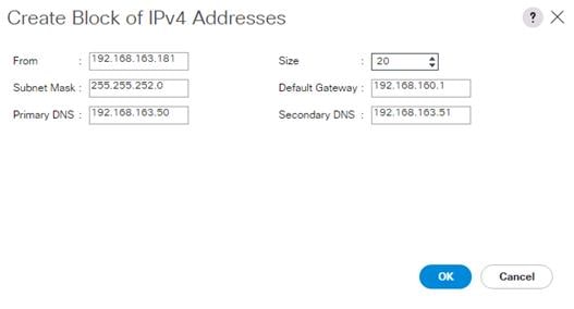
![]() This block of IP addresses should be in the out of band management subnet.
This block of IP addresses should be in the out of band management subnet.
5. Click OK.
6. Click OK in the confirmation message.
Synchronize Cisco UCS to NTP
To synchronize the Cisco UCS environment to the NTP server, follow these steps:
1. In Cisco UCS Manager, click the Admin tab in the navigation pane.
2. Select All > Timezone Management > Timezone.
3. In the Properties pane, select the appropriate time zone in the Timezone menu.
4. Click Save Changes, and then click OK.
5. Click Add NTP Server.
6. Enter <NTP Server IP Address> and click OK.
7. Click OK.
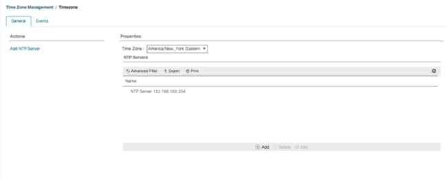
Add Additional DNS Server(s)
To add one or more additional DNS servers to the Cisco UCS environment, follow these steps:
1. In Cisco UCS Manager, click Admin.
2. Expand All > Communications Management.
3. Select DNS Management.
4. In the Properties pane, select Specify DNS Server.
5. Enter the IP address of the additional DNS server.
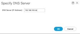
6. Click OK and then click OK again. Repeat this process for any additional DNS servers.
Add an Additional Administrator User
To add an additional locally authenticated Administrative user (versaadmin) to the Cisco UCS environment in case issues arise with the admin user, follow these steps:
1. In Cisco UCS Manager, click Admin.
2. Expand User Management > User Services > Locally Authenticated Users.
3. Right-click Locally Authenticated Users and select Create User.
4. In the Create User fields it is only necessary to fill in the Login ID, Password, and Confirm Password fields. Fill in the Create User fields according to your local security policy.
5. Leave the Account Status field set to Active.
6. Set Account Expires according to your local security policy.
7. Under Roles, select admin.
8. Leave Password Required selected for the SSH Type field.
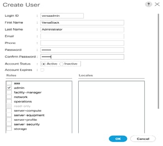
9. Click OK and then Click OK again to complete adding the user.
Enable Port Auto-Discovery Policy
To enable the port auto-discovery policy, follow these steps:
1. Setting the port auto-discovery policy enables automatic discovery of Cisco UCS B-Series chassis server ports.
2. In Cisco UCS Manager, click Equipment, select All > Equipment in the Navigation Pane, and select the Policies tab on the right.
3. Under Port Auto-Discovery Policy, set Auto Configure Server Port to Enabled.
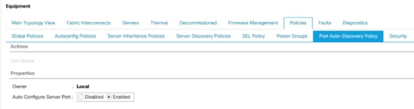
4. Click Save Changes and then OK.
Enable Info Policy for Neighbor Discovery
Enabling the info policy enables Fabric Interconnect neighbor information to be displayed. To modify the info policy, follow these steps:
1. In Cisco UCS Manager, click Equipment, select All > Equipment in the Navigation Pane, and select the Policies tab on the right.
2. Under Global Policies, scroll down to Info Policy and select Enabled for Action.

3. Click Save Changes and then OK.
4. Under Equipment, select Fabric Interconnect A (primary). On the right, select the Neighbors tab. CDP information is shown under the LAN tab and LLDP information is shown under the LLDP tab.
Edit Chassis Discovery Policy
Setting the discovery policy simplifies the addition of B-Series Cisco UCS chassis and of additional fabric extenders for further C-Series connectivity. To modify the chassis discovery policy, follow these steps:
1. In Cisco UCS Manager, click the Equipment tab in the navigation pane and select Equipment from the list in the left pane.
2. In the right pane, click the Policies tab.
3. Under Global Policies, set the Chassis/FEX Discovery Policy to match the minimum number of uplink ports that are cabled between any chassis IOM or fabric extender (FEX) and the fabric interconnects.
![]() If varying numbers of links between chassis and the Fabric Interconnects will be used, leave Action set to 1 Link.
If varying numbers of links between chassis and the Fabric Interconnects will be used, leave Action set to 1 Link.
4. On the 6454 Fabric Interconnects, the Link Grouping Preference is automatically set to Port Channel and is greyed out. On a 6300 Series or 6200 Series Fabric Interconnect, set the Link Grouping Preference to Port Channel. If Backplane Speed Preference appears, leave it set at 40G.
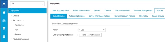
5. If any changes have been made, Click Save Changes.
6. Click OK.
Enable Server and Uplink Ports
To enable and verify server and uplink ports, follow these steps:
1. In Cisco UCS Manager, click the Equipment tab in the navigation pane.
2. Select Equipment > Fabric Interconnects > Fabric Interconnect A (primary) > Fixed Module.
3. Expand Fixed Module.
4. Expand and select Ethernet Ports.
5. Select the ports that are connected to the Cisco UCS 5108 chassis and Cisco UCS C-Series servers, one by one, right-click and select Configure as Server Port.
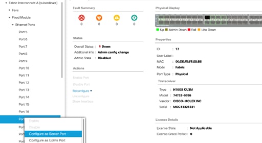
6. Click Yes to confirm server ports and click OK.
7. Verify that the ports connected to the UCS 5108 chassis and C-series servers are now configured as Server ports by selecting Fabric Interconnect A in the left and Physical Ports tab in the right pane.
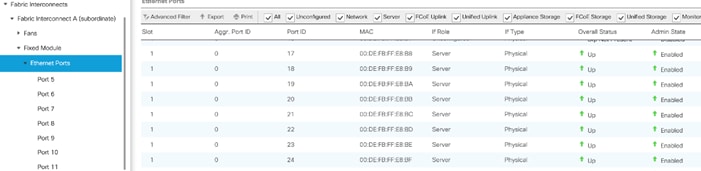
8. Select the ports that are connected to the Cisco Nexus 9336C-FX2 switches, one by one, right-click and select Configure as Uplink Port.
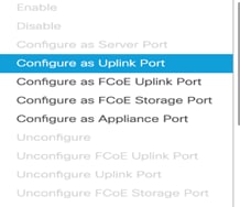
9. Click Yes to confirm uplink ports and click OK.
10. Verify that the uplink ports are now configured as Network ports by selecting Fabric Interconnect A in the left and Physical Ports tab in the right pane.
![]()
11. Select Equipment > Fabric Interconnects > Fabric Interconnect B (subordinate) > Fixed Module.
12. Repeat steps 1-11 to configure server and uplink ports on Fabric Interconnect B.
Acknowledge Cisco UCS Chassis and FEX
When the UCS FI ports are configured as server ports, UCS chassis is automatically discovered and may need to be acknowledged. To acknowledge all Cisco UCS chassis, follow these steps:
1. In Cisco UCS Manager, click the Equipment tab in the navigation pane.
2. Expand Chassis and select each chassis that is listed.
3. Right-click each chassis and select Acknowledge Chassis.
4. Click Yes and then click OK to complete acknowledging the chassis.
5. If Nexus FEXes are part of the configuration, expand Rack Mounts and FEX.
6. Right-click each FEX that is listed and select Acknowledge FEX.
7. Click Yes and then click OK to complete acknowledging the FEX.
Create Port Channels for Ethernet Uplinks
To configure the necessary Ethernet port channels out of the Cisco UCS environment, follow these steps:
![]() In this procedure, two port channels are created one from each Fabric Interconnect (A and B) to both the Cisco Nexus 9336C-FX2 switches.
In this procedure, two port channels are created one from each Fabric Interconnect (A and B) to both the Cisco Nexus 9336C-FX2 switches.
1. In Cisco UCS Manager, click the LAN tab in the navigation pane.
2. Under LAN > LAN Cloud, expand the Fabric A tree.
3. Right-click Port Channels and choose Create Port Channel.
4. Enter 40 as the unique ID of the port channel.
5. Enter Po40 as the name of the port channel and click Next.
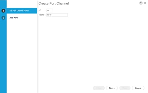
6. Select the network uplink ports to be added to the port channel.
7. Click >> to add the ports to the port channel (49 and 50 in this design).
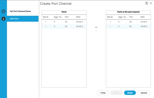
8. Click Finish to create the port channel and then click OK.
9. In the navigation pane, under LAN > LAN Cloud > Fabric A > Port Channels, select Port-Channel 40. Select 100 Gbps for the Admin Speed.
10. Click Save Changes and OK. After a few minutes, verify that the Overall Status is Up and the Operational Speed is correct.
11. In the navigation pane, under LAN > LAN Cloud, expand the Fabric B tree.
12. Right-click Port Channels and choose Create Port Channel.
13. Enter 50 as the unique ID of the port channel.
14. Enter Po50 as the name of the port channel and click Next.
15. Select the network uplink ports (49 and 50 in this design) to be added to the port channel.
16. Click >> to add the ports to the port channel.
17. Click Finish to create the port channel and click OK.
18. In the navigation pane, under LAN > LAN Cloud > Fabric B > Port Channels, select Port-Channel 50. Select 100 Gbps for the Admin Speed.
19. Click Save Changes and OK. After a few minutes, verify that the Overall Status is Up and the Operational Speed is correct.
Create MAC Address Pools
To configure the necessary MAC address pools for the Cisco UCS environment, follow these steps:
1. In Cisco UCS Manager, click the LAN tab in the navigation pane.
2. Select Pools > root.
![]() In this procedure, two MAC address pools are created, one for each switching fabric.
In this procedure, two MAC address pools are created, one for each switching fabric.
3. Right-click MAC Pools under the root organization.
4. Select Create MAC Pool to create the MAC address pool.
5. Enter MAC-Pool-A as the name of the MAC pool.
6. Optional: Enter a description for the MAC pool.
7. Select the option Sequential for the Assignment Order field and click Next.
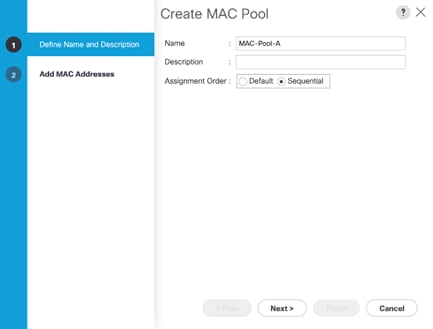
8. Click Add.
9. Specify a starting MAC address.
![]() It is recommended to place 0A in the second last octet of the starting MAC address to identify all of the MAC addresses as Fabric A addresses. It is also recommended to not change the first three octets of the MAC address.
It is recommended to place 0A in the second last octet of the starting MAC address to identify all of the MAC addresses as Fabric A addresses. It is also recommended to not change the first three octets of the MAC address.
10. Specify a size for the MAC address pool that is sufficient to support the available blade or rack server resources. Remember that multiple Cisco VIC vNICs will be created on each server and each vNIC will be assigned a MAC address.
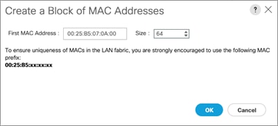
11. Click OK and then click Finish.
12. In the confirmation message, click OK.
13. Right-click MAC Pools under the root organization.
14. Select Create MAC Pool to create the MAC address pool.
15. Enter MAC-Pool-B as the name of the MAC pool.
16. Optional: Enter a description for the MAC pool.
17. Select the Sequential Assignment Order and click Next.
18. Click Add.
19. Specify a starting MAC address.
![]() It is recommended to place 0B in the second last octet of the starting MAC address to identify all the MAC addresses in this pool as fabric B addresses. It is also recommended to not change the first three octets of the MAC address.
It is recommended to place 0B in the second last octet of the starting MAC address to identify all the MAC addresses in this pool as fabric B addresses. It is also recommended to not change the first three octets of the MAC address.
20. Specify a size for the MAC address pool that is sufficient to support the available blade or rack server resources.
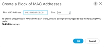
21. Click OK and then click Finish.
22. In the confirmation message, click OK.
Create UUID Suffix Pool
To configure the necessary universally unique identifier (UUID) suffix pool for the Cisco UCS environment, follow these steps:
1. In Cisco UCS Manager, click the Servers tab in the navigation pane.
2. Select Pools > root.
3. Right-click UUID Suffix Pools and choose Create UUID Suffix Pool.
4. Enter UUID-Pool as the name of the UUID suffix pool.
5. Optional: Enter a description for the UUID suffix pool.
6. Keep the prefix at the derived option.
7. Change the Assignment Order to Sequential.
8. Click Next.
9. Click Add to add a block of UUIDs.
10. Keep the From field at the default setting.
11. Specify a size for the UUID block that is sufficient to support the available blade or rack server resources.
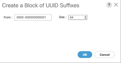
12. Click OK. Click Finish and then click OK.
Create Server Pool
To configure the necessary server pool for the Cisco UCS environment, follow these steps:
1. In Cisco UCS Manager, click the Servers tab in the navigation pane.
2. Select Pools > root.
3. Right-click Server Pools and choose Create Server Pool.
4. Enter Infra-Server-Pool as the name of the server pool.
5. Optional: Enter a description for the server pool.
6. Click Next.
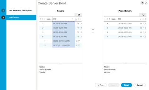
7. Select at least two (or more) servers to be used for the setting up the VMware environment and click >> to add them to the Infra-Server-Pool server pool.
8. Click Finish and click OK.
![]() If Cisco UCS C-Series servers are leveraged in the design, create storage pool by selecting the appropriate server models intended to be used.
If Cisco UCS C-Series servers are leveraged in the design, create storage pool by selecting the appropriate server models intended to be used.
Create IQN Pools for iSCSI Boot and LUN Access
To enable iSCSI boot and provide access to iSCSI LUNs, configure the necessary IQN pools in the Cisco UCS Manager by completing the following steps:
1. In the Cisco UCS Manager, select the SAN tab.
2. Select Pools > root.
3. Right-click IQN Pools under the root organization and choose Create IQN Suffix Pool to create the IQN pool.
4. Enter Infra-IQN-Pool for the name of the IQN pool.
5. Optional: Enter a description for the IQN pool.
6. Enter iqn.1992-08.com.cisco as the prefix
7. Select the option Sequential for Assignment Order field. Click Next.
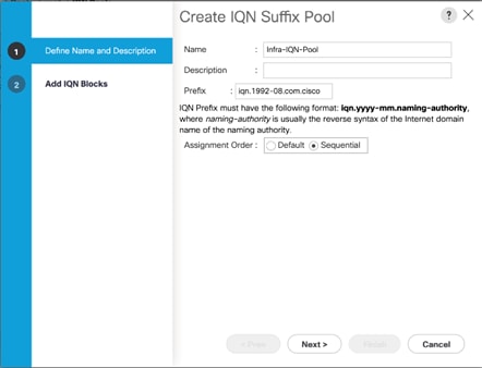
8. Click Add.
9. Enter an identifier with ucs-host as the suffix. Optionally a rack number or any other identifier can be added to the suffix to make the IQN unique within a DC.
10. Enter 1 in the From field.
11. Specify a size of the IQN block sufficient to support the available server resources. Each server will receive one IQN.
12. Click OK.
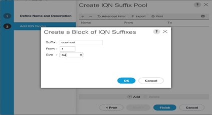
13. Click Finish. In the message box that displays, click OK.
Create IP Pools for iSCSI Boot and LUN Access
For enabling iSCSI storage access, these steps provide details for configuring the necessary IP pools in the Cisco UCS Manager:
![]() Two IP pools are created, one for each switching fabric.
Two IP pools are created, one for each switching fabric.
1. In Cisco UCS Manager, select the LAN tab.
2. Select Pools > root.
3. Right-click IP Pools under the root organization and choose Create IP Pool to create the IP pool.
4. Enter iSCSI-initiator-A for the name of the IP pool.
5. Optional: Enter a description of the IP pool.
6. Select the option Sequential for the Assignment Order field. Click Next.
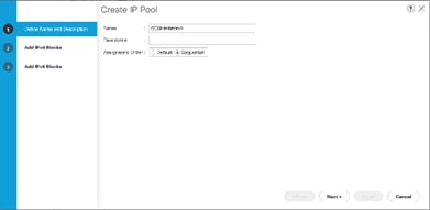
7. Click Add.
8. In the From field, enter the beginning of the range to assign an iSCSI-A IP address. These addresses are covered in Table 2 .
9. Enter the Subnet Mask.
10. Set the size with sufficient address range to accommodate the servers. Click OK.
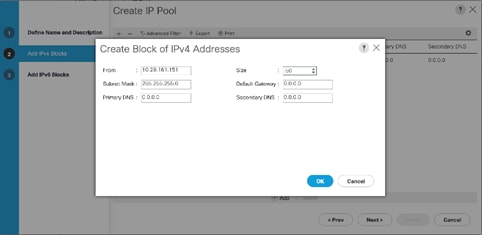
11. Click Next and then click Finish.
12. Click OK in the confirmation message.
13. Right-click IP Pools under the root organization and choose Create IP Pool to create the IP pool.
14. Enter iSCSI-initiator-B for the name of the IP pool.
15. Optional: Enter a description of the IP pool.
16. Select the Sequential option for the Assignment Order field. Click Next.
17. Click Add.
18. In the From field, enter the beginning of the range to assign an iSCSI-B IP address. These addresses are covered in Table 2 .
19. Enter the Subnet Mask.
20. Set the size with sufficient address range to accommodate the servers. Click OK.
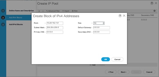
21. Click Next and then click Finish.
22. Click OK in the confirmation message.
Create VLANs
To configure the necessary VLANs in the Cisco UCS Manager, follow these steps for all the VLANs listed Table 26 :
| VLAN Name |
VLAN |
| IB-Mgmt |
11 |
| iSCSI-A |
3161 |
| iSCSI-B |
3162 |
| vMotion |
3173 |
| Native-2 |
2 |
1. In Cisco UCS Manager, click the LAN tab in the navigation pane.
2. Select LAN > LAN Cloud.
3. Right-click VLANs and choose Create VLANs.
4. Enter name from the VLAN Name column.
5. Keep the Common/Global option selected for the scope of the VLAN.
6. Enter the VLAN ID associated with the name.
7. Keep the Sharing Type as None.
8. Click OK and then click OK again.
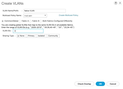
9. Click Yes and then click OK twice.
10. Repeat steps 1-9 for all the VLANs in Table 26 .
Create Host Firmware Package
Firmware management policies allow the administrator to select the corresponding packages for a given server configuration. These policies often include packages for adapter, BIOS, board controller, FC adapters, host bus adapter (HBA) option ROM, and storage controller.
To create a firmware management policy for a given server configuration in the Cisco UCS environment, follow these steps:
1. In Cisco UCS Manager, click the Servers tab in the navigation pane.
2. Select Policies > root.
3. Right-click Host Firmware Packages and choose Create Host Firmware Package.
4. Enter Infra-FW-Pack as the name of the host firmware package.
5. Keep the Host Firmware Package as Simple.
6. Select the version 4.0(4e) for both the Blade and Rack Packages.
7. Click OK to create the host firmware package.
8. Click OK.
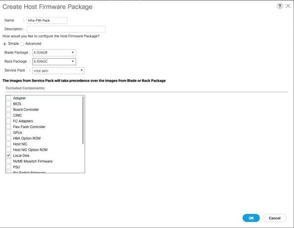
Set Jumbo Frames in Cisco UCS Fabric
Jumbo Frames are used in VersaStack for the iSCSI storage protocols. The normal best practice in VersaStack has been to set the MTU of the Best Effort QoS System Class in Cisco UCS Manager to 9216 for Jumbo Frames. In the Cisco UCS 6454 Fabric Interconnect the MTU for the Best Effort QoS System Class is fixed at normal and cannot be changed. Testing has shown that even with this setting of normal in the 6454, Jumbo Frames can pass through the Cisco UCS fabric without being dropped. The screenshot below is from Cisco UCS Manager on a 6454 Fabric Interconnect, where the MTU for the Best Effort class is not configurable.
To configure jumbo frames in the Cisco UCS fabric in a 6300 or 6200 series Fabric Interconnect, follow these steps:
1. In Cisco UCS Manager, click the LAN tab in the navigation pane.
2. Select LAN > LAN Cloud > QoS System Class.
3. In the right pane, click the General tab.
4. On the Best Effort row, enter 9216 in the box under the MTU column.
5. Click Save Changes in the bottom of the window.
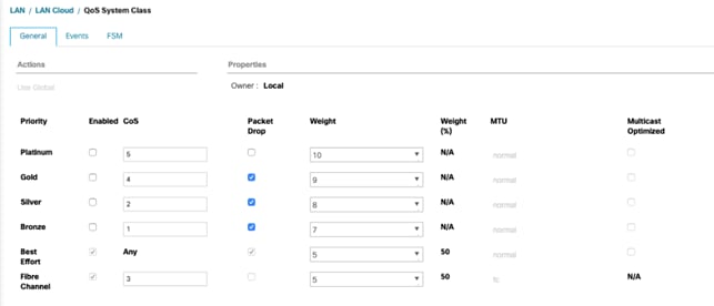
6. Click OK.
Create Local Disk Configuration Policy
When using an external storage system for OS boot, a local disk configuration for the Cisco UCS environment is necessary because the servers in the environment will not contain a local disk.
![]() This policy should not be applied to the servers that contain local disks.
This policy should not be applied to the servers that contain local disks.
To create a local disk configuration policy for no local disks, follow these steps:
1. In Cisco UCS Manager, click the Servers tab in the navigation pane.
2. Select Policies > root.
3. Right-click Local Disk Config Policies and choose Create Local Disk Configuration Policy.
4. Enter SAN-Boot as the local disk configuration policy name.
5. Change the mode to No Local Storage.
6. Click OK to create the local disk configuration policy.
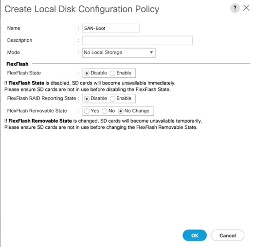
7. Click OK again.
Create Network Control Policy for Cisco Discovery Protocol (CDP) and Link Layer Discovery Protocol (LLDP)
To create a network control policy that enables Link Layer Discovery Protocol (LLDP) on virtual network ports, follow these steps:
1. In Cisco UCS Manager, click the LAN tab in the navigation pane.
2. Select Policies > root.
3. Right-click Network Control Policies and choose Create Network Control Policy.
4. Enter Enable-CDP-LLDP as the policy name.
5. For CDP, select Enabled option.
6. For LLDP, scroll down and select Enabled for both Transit and Receive.
7. Click OK to create the network control policy.
8. Click OK.
Create Power Control Policy
To create a power control policy for the Cisco UCS environment, follow these steps:
1. In Cisco UCS Manager, click the Servers tab in the navigation pane.
2. Select Policies > root.
3. Right-click Power Control Policies and choose Create Power Control Policy.
4. Enter No-Power-Cap as the power control policy name.
5. Change the power capping setting to No Cap.
6. Click OK to create the power control policy.
7. Click OK.
Create Server Pool Qualification Policy (Optional)
To create an optional server pool qualification policy for the Cisco UCS environment, follow these steps:
![]() This example creates a policy for selecting a Cisco UCS B200-M5 server.
This example creates a policy for selecting a Cisco UCS B200-M5 server.
1. In Cisco UCS Manager, click the Servers tab in the navigation pane.
2. Select Policies > root.
3. Right-click Server Pool Policy Qualifications and choose Create Server Pool Policy Qualification.
4. Enter UCSB-B200-M5 as the name for the policy.
5. Choose Create Server PID Qualifications.
6. Select UCSB-B200-M5 as the PID.
7. Click OK.
8. Click OK to create the server pool policy qualification.
![]() The server pool qualification policy name and the PID values varies if the UCS C-Series or other B-Series server models are used, select appropriate values based on the server model being used.
The server pool qualification policy name and the PID values varies if the UCS C-Series or other B-Series server models are used, select appropriate values based on the server model being used.
Create Server BIOS Policy
To create a server BIOS policy for the Cisco UCS environment, follow these steps:
1. In Cisco UCS Manager, click the Servers tab in the navigation pane.
2. Select Policies > root.
3. Right-click BIOS Policies and choose Create BIOS Policy.
4. Enter Infra-Host-BIOS as the BIOS policy name.
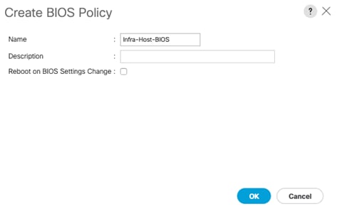
5. Click OK, then OK again to create the BIOS Policy.
6. Select the newly created BIOS Policy.
7. Set the following within the Main tab of the Policy:
a. CDN Control -> Enabled
b. Quiet Boot -> Disabled
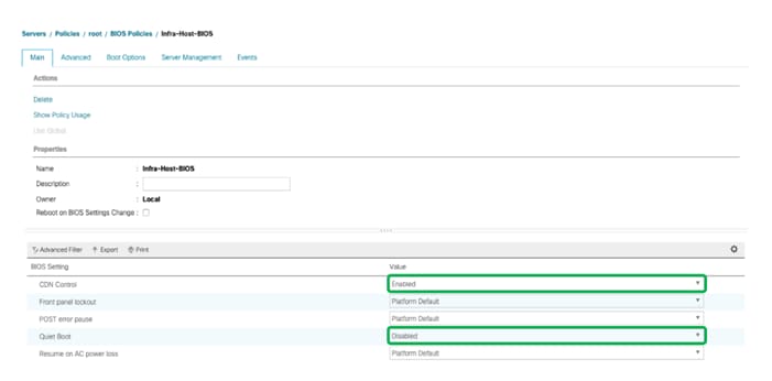
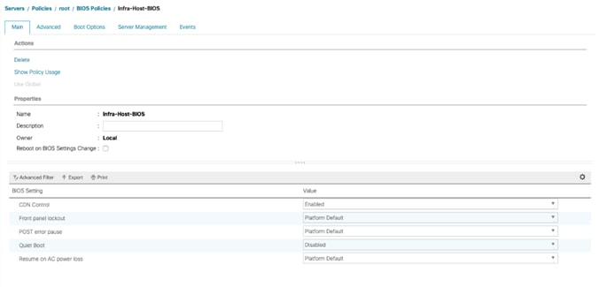
8. Click the Advanced tab, leaving the Processor tab selected within the Advanced tab. Set the following within the Processor tab:
a. DRAM Clock Throttling -> Performance
b. Frequency Floor Override -> Enabled
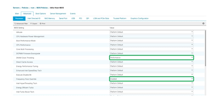
9. Scroll down to the remaining Processor options and select:
a. Processor C State -> Disabled
b. Processor C1E -> Disabled
c. Processor C3 Report -> Disabled
d. Processor C7 Report -> Disabled
e. Energy Performance -> Performance
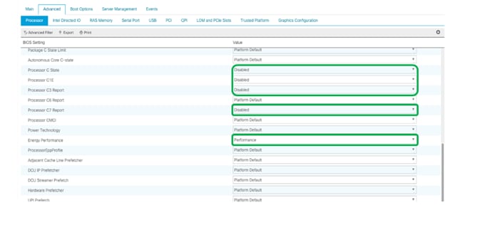
10. Click the RAS Memory tab, and select:
a. LV DDR Mode -> Performance Mode
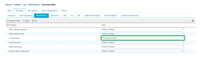
11. Click Save Changes to modify the BIOS policy.
12. Click OK.
Update Default Maintenance Policy
To update the default Maintenance Policy, follow these steps:
1. In Cisco UCS Manager, click the Servers tab in the navigation pane.
2. Select Policies > root and then select Maintenance Policies > default.
3. Change the Reboot Policy to User Ack.
4. Check the box to enable On Next Boot.
5. Click Save Changes.
6. Click OK to accept the change.
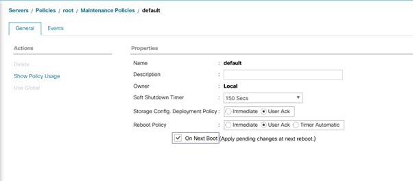
Create vNIC/vHBA Placement Policy
To create a vNIC/vHBA placement policy for the infrastructure hosts, follow these steps:
1. In Cisco UCS Manager, click the Servers tab in the navigation pane.
2. Select Policies > root.
3. Right-click vNIC/vHBA Placement Policies and choose Create Placement Policy.
4. Enter Infra-Policy as the name of the placement policy.
5. Click 1 and select Assigned Only.
6. Click OK and then click OK again.
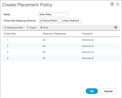
Create vNIC Templates
To create multiple virtual network interface card (vNIC) templates for the Cisco UCS environment, follow these steps. A total of 6 vNIC Templates will be created as covered below in Table 27 .
Table 27 vNIC Templates and Associated VLANs
| Name |
Fabric ID |
VLANs |
Native VLAN |
MAC Pool |
| vNIC_Infra_A
|
A |
IB-Mgmt, Native-2, vMotion |
Native-2 |
MAC-Pool-A |
| vNIC_Infra_B |
B |
IB-Mgmt, Native-2, vMotion |
Native-2 |
MAC-Pool-B |
| vNIC_vDS_A
|
A |
VM Network |
|
MAC-Pool-A |
| vNIC_vDS_B
|
B |
VM Network |
|
MAC-Pool-B |
| vNIC_iSCSI_A |
A |
iSCSI-A |
iSCSI-A |
MAC-Pool-A |
| vNIC_iSCSI_B |
B |
iSCSI-B |
iSCSI-B |
MAC-Pool-B |
Create Infrastructure vNIC Templates
For the vNIC_Infra_A Template, follow these steps:
1. In Cisco UCS Manager, click the LAN tab in the navigation pane.
2. Select Policies > root.
3. Right-click vNIC Templates.
4. Select Create vNIC Template.
5. Enter vNIC_Infra_A as the vNIC template name.
6. Keep Fabric A selected.
7. Optional: select the Enable Failover checkbox.
![]() Selecting Failover can improve link failover time by handling it at the hardware level and can guard against any potential for NIC failure not being detected by the virtual switch.
Selecting Failover can improve link failover time by handling it at the hardware level and can guard against any potential for NIC failure not being detected by the virtual switch.
8. Select Primary Template for the Redundancy Type.
9. Leave Peer Redundancy Template as <not set>
![]() Redundancy Type and specification of Redundancy Template are configuration options to later allow changes to the Primary Template to automatically adjust onto the Secondary Template.
Redundancy Type and specification of Redundancy Template are configuration options to later allow changes to the Primary Template to automatically adjust onto the Secondary Template.
10. Under Target, make sure that the VM checkbox is not selected.
11. Select Updating Template as the Template Type.
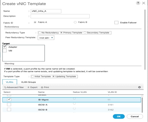
12. Under VLANs, select the checkboxes for IB-Mgmt, vMotion and Native-VLAN VLANs.
13. Set Native-VLAN as the native VLAN.
14. Leave vNIC Name selected for the CDN Source.
15. Leave 9000 for the MTU.
16. In the MAC Pool list, select MAC_Pool_A.
17. In the Network Control Policy list, select Enable-CDP-LLDP.
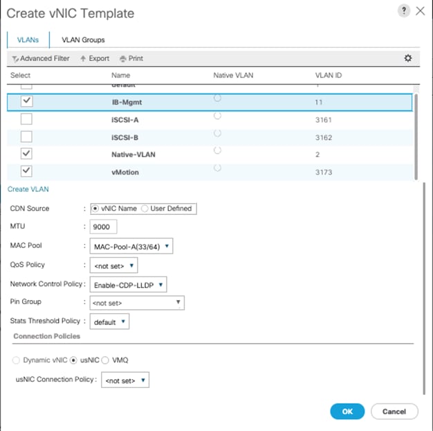
18. Click OK to create the vNIC template.
19. Click OK.
For the vNIC_Infra_B Template, follow these steps:
1. In the navigation pane, select the LAN tab.
2. Select Policies > root.
3. Right-click vNIC Templates.
4. Select Create vNIC Template.
5. Enter vNIC_Infra_B as the vNIC template name.
6. Select Fabric B.
7. Select Secondary Template for Redundancy Type.
8. For the Peer Redundancy Template drop-down, select vNIC_Infra_A.
![]() With Peer Redundancy Template selected, Failover specification, Template Type, VLANs, CDN Source, MTU, and Network Control Policy are all pulled from the Primary Template.
With Peer Redundancy Template selected, Failover specification, Template Type, VLANs, CDN Source, MTU, and Network Control Policy are all pulled from the Primary Template.
9. Under Target, make sure the VM checkbox is not selected.
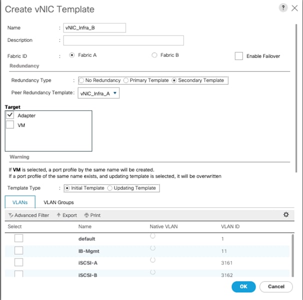
10. In the MAC Pool list, select MAC_Pool_B.
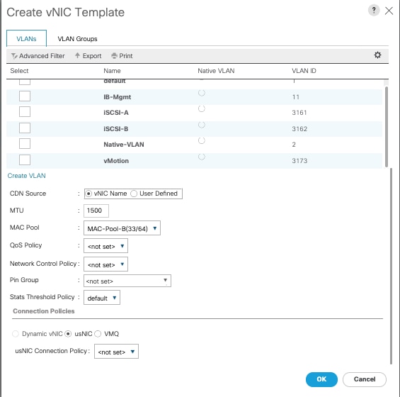
11. Click OK to create the vNIC template.
12. Click OK.
Create vNIC Templates for APIC-Integrated Virtual Switch
To create the vNIC_VDS_A Template, follow these steps:
1. In Cisco UCS Manager, click the LAN tab in the navigation pane.
2. Select Policies > root.
3. Right-click vNIC Templates.
4. Select Create vNIC Template.
5. Enter vNIC_VDS_A as the vNIC template name.
6. Keep Fabric A selected.
7. Optional: select the Enable Failover checkbox.
8. Leave No Redundancy selected for the Redundancy Type.
9. Under Target, make sure that the VM checkbox is not selected.
10. Select Updating Template as the Template Type.
11. Do not set a native VLAN.

12. For MTU, enter 9000.
13. In the MAC Pool list, select MAC_Pool_A.
14. In the Network Control Policy list, select Enable-CDP-LLDP.
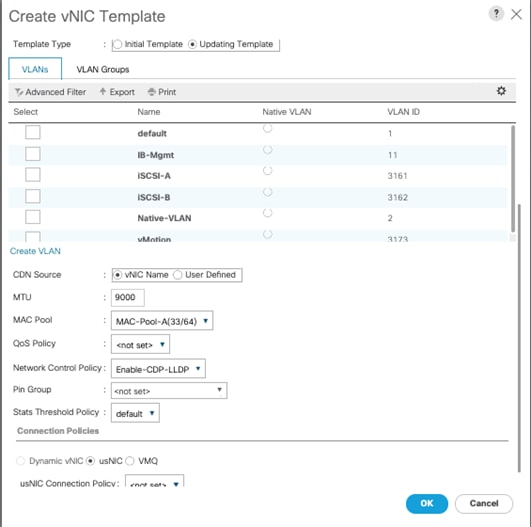
15. Click OK to create the vNIC template.
16. Click OK.
To create the vNIC_VDS_B Templates, follow these steps:
1. In the navigation pane, select the LAN tab.
17. Select Policies > root.
18. Right-click vNIC Templates.
19. Select Create vNIC Template.
20. Enter vNIC_VDS_B as the vNIC template name.
21. Select Fabric B.
22. Leave No Redundancy selected for the Redundancy Type.
![]() Peer Redundancy has not been configured between the two vDS vNIC Templates because with the vDS VMM implementation configured later will update both vNIC Templates using the Cisco UCS integration.
Peer Redundancy has not been configured between the two vDS vNIC Templates because with the vDS VMM implementation configured later will update both vNIC Templates using the Cisco UCS integration.
23. Under Target, make sure the VM checkbox is not selected.
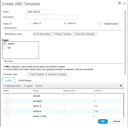
24. For MTU, enter 9000.
25. In the MAC Pool list, select MAC_Pool_B.
26. In the Network Control Policy list, select Enable-CDP-LLDP.
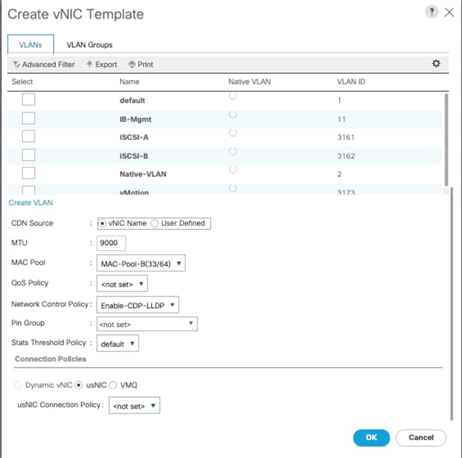
27. Click OK to create the vNIC template.
28. Click OK.
Create iSCSI vNIC Templates
To create iSCSI Boot vNICs, follow these steps:
1. In Cisco UCS Manager, click the LAN tab in the navigation pane.
2. Select Policies > root.
3. Right-click vNIC Templates.
4. Select Create vNIC Template.
5. Enter vNIC_iSCSI_A as the vNIC template name.
6. Keep Fabric A selected.
7. Do not select the Enable Failover checkbox.
8. Keep the No Redundancy options selected for the Redundancy Type.
9. Under Target, make sure that the Adapter checkbox is selected.
10. Select Updating Template as the Template Type.
11. Under VLANs, select iSCSI-A VLAN as the only VLAN and set it as the Native VLAN.
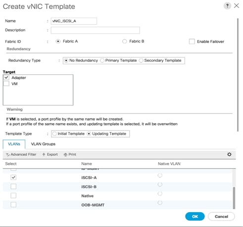
12. For MTU, enter 9000.
13. In the MAC Pool list, select MAC_Pool_A.
14. In the Network Control Policy list, select Enable-CDP-LLDP.
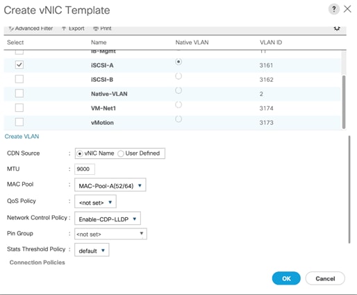
15. Click OK to create the vNIC template.
16. Click OK.
To create the vNIC_iSCSI_B Template, follow these steps:
1. In the navigation pane, select the LAN tab.
2. Select Policies > root.
3. Right-click vNIC Templates.
4. Select Create vNIC Template.
5. Enter vNIC_iSCSI_B as the vNIC template name.
6. Keep Fabric B selected.
7. Do not select the Enable Failover checkbox.
8. Keep the No Redundancy options selected for the Redundancy Type.
9. Under Target, make sure that the Adapter checkbox is selected.
10. Select Updating Template as the Template Type.
11. Under VLANs, select iSCSI-B VLAN as the only VLAN and set it as the Native VLAN.
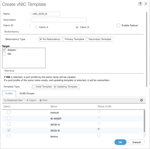
12. For MTU, enter 9000.
13. In the MAC Pool list, select MAC_Pool_B.
14. In the Network Control Policy list, select Enable-CDP-LLDP.
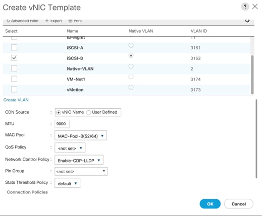
15. Click OK to create the vNIC template.
16. Click OK.
Create LAN Connectivity Policy
To configure the necessary Infrastructure LAN Connectivity Policy, follow these steps:
1. In Cisco UCS Manager, click LAN on the left.
2. Select LAN > Policies > root.
3. Right-click LAN Connectivity Policies.
4. Select Create LAN Connectivity Policy.
5. Enter iSCSI-LAN-Policy as the name of the policy.
6. Click the upper Add button to add a vNIC.
7. In the Create vNIC dialog box, enter 00-Infra-A as the name of the vNIC.
![]() The numeric prefix of “00-“ and subsequent increments on the later vNICs are used in the vNIC naming to force the device ordering through Consistent Device Naming (CDN). Without this, some operating systems might not respect the device ordering that is set within Cisco UCS.
The numeric prefix of “00-“ and subsequent increments on the later vNICs are used in the vNIC naming to force the device ordering through Consistent Device Naming (CDN). Without this, some operating systems might not respect the device ordering that is set within Cisco UCS.
8. Select the Use vNIC Template checkbox.
9. In the vNIC Template list, select 00-Infra-A.
10. In the Adapter Policy list, select VMWare.
11. Click OK to add this vNIC to the policy.

12. Click the upper Add button to add another vNIC to the policy.
13. In the Create vNIC box, enter 01-Infra-B as the name of the vNIC.
14. Select the Use vNIC Template checkbox.
15. In the vNIC Template list, select 01-Infra-B.
16. In the Adapter Policy list, select VMWare.

17. Click OK to add the vNIC to the policy.
18. Click the upper Add button to add a vNIC.
19. In the Create vNIC dialog box, enter 02-VDS-A as the name of the vNIC.
20. Select the Use vNIC Template checkbox.
21. In the vNIC Template list, select vNIC_VDS_A.
22. In the Adapter Policy list, select VMWare.
23. Click OK to add this vNIC to the policy.

24. Click the upper Add button to add a vNIC to the policy.
25. In the Create vNIC dialog box, enter 03-VDS-B as the name of the vNIC.
26. Select the Use vNIC Template checkbox.
27. In the vNIC Template list, select vNIC_VDS_B.
28. In the Adapter Policy list, select VMWare.

29. Click OK to add this vNIC to the policy.
30. Click the upper Add button to add a vNIC.
31. In the Create vNIC dialog box, enter 04-iSCSI-A as the name of the vNIC.
32. Select the Use vNIC Template checkbox.
33. In the vNIC Template list, select vNIC_iSCSI-A.
34. In the Adapter Policy list, select VMWare.

35. Click OK to add this vNIC to the policy.
36. Click the upper Add button to add a vNIC to the policy.
37. In the Create vNIC dialog box, enter 05-iSCSI-B as the name of the vNIC.
38. Select the Use vNIC Template checkbox.
39. In the vNIC Template list, select vNIC_iSCSI-B.
40. In the Adapter Policy list, select VMWare.
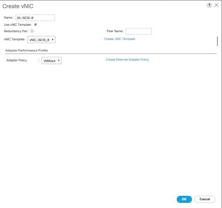
41. Click OK to add this vNIC to the policy.
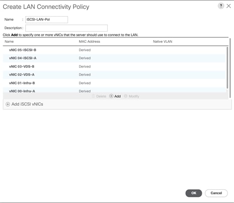
Add iSCSI vNICs in LAN Policy
To add iSCSI vNICs in LAN Policy created earlier, follow these steps:
1. Verify the iSCSI base vNICs are already added as part of vNIC implementation.
2. Expand the Add iSCSI vNICs section to add the iSCSI boot vNICs.
3. Select Add in the Add iSCSI vNICs section.
4. Set the name to iSCSI—A-vNIC.
5. Select the 04-iSCSI-A as Overlay vNIC.
6. Set the VLAN to iSCSI-A (native) VLAN.
7. Set the iSCSI Adapter Policy to default.
8. Leave the MAC Address set to None.
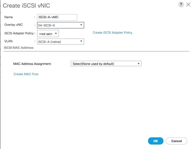
9. Click OK.
10. Select Add in the Add iSCSI vNICs section.
11. Set the name to iSCSI-B-vNIC.
12. Select the 05-iSCSI-B as Overlay vNIC.
13. Set the VLAN to iSCSI-B (native) VLAN.
14. Set the iSCSI Adapter Policy to default.
15. Leave the MAC Address set to None.
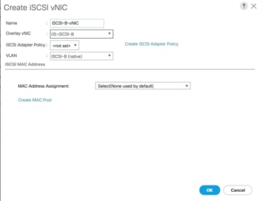
16. Click OK then click OK again to create the LAN Connectivity Policy.
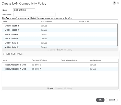
Create iSCSI Boot Policy
This procedure applies to a Cisco UCS environment in which iSCSI interface on IBM FS9100 Controller Node A is chosen as the primary target.
To create the boot policy for the Cisco UCS environment, follow these steps:
1. In Cisco UCS Manager, click the Servers tab in the navigation pane.
2. Select Policies > root.
3. Right-click Boot Policies and choose Create Boot Policy.
4. Enter Boot-iSCSI-A as the name of the boot policy.
5. Optional: Enter a description for the boot policy.
6. Keep the Reboot on Boot Order Change option cleared.
7. Expand the Local Devices drop-down list and select Add Remote CD/DVD.
8. Expand the iSCSI vNICs section and select Add iSCSI Boot.
9. In the Add iSCSI Boot dialog box, enter iSCSI-A-vNIC.
10. Click OK.
11. Select Add iSCSI Boot.
12. In the Add iSCSI Boot dialog box, enter iSCSI-B-vNIC.
13. Click OK.
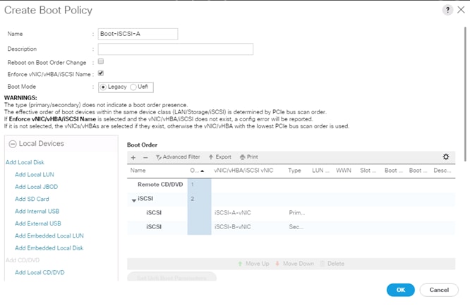
14. Click OK then OK again to save the boot policy.
Create iSCSI Boot Service Profile Template
Service profile template configuration for the iSCSI-based SAN access is explained in this section.
To create the service profile template, follow these steps:
1. In Cisco UCS Manager, click the Servers tab in the navigation pane.
2. Select Service Profile Templates > root.
3. Right-click root.
4. Select Create Service Profile Template to open the Create Service Profile Template wizard.
5. Enter Infra-ESXi-iSCSI-Host as the name of the service profile template. This service profile template is configured to boot from FS9100 storage node 1 on fabric A.
6. Select the “Updating Template” option.
7. Under UUID, select UUID_Pool as the UUID pool.
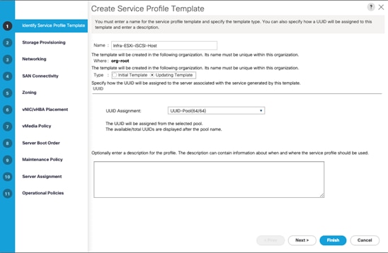
8. Click Next.
Configure Storage Provisioning
To configure the storage provisioning, follow these steps:
1. If you have servers with no physical disks, click the Local Disk Configuration Policy tab and select the SAN-Boot Local Storage Policy. Otherwise, select the default Local Storage Policy.
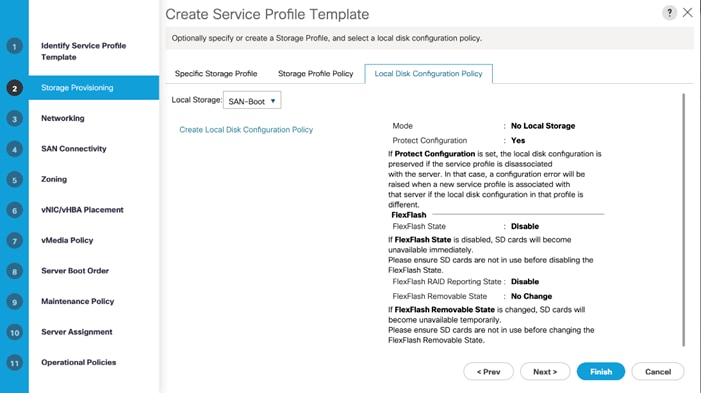
2. Click Next.
Configure Networking Options
To configure the network options, follow these steps:
1. Keep the default setting for Dynamic vNIC Connection Policy.
2. Select the “Use Connectivity Policy” option to configure the LAN connectivity.
3. Select iSCSI-LAN-Policy from the LAN Connectivity Policy drop-down list.
4. Select IQN_Pool in Initiator Name Assignment.
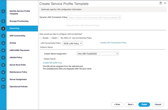
5. Click Next.
Configure Storage Options
1. Select the No vHBA option for the “How would you like to configure SAN connectivity?” field.
2. Click Next.
Configure Zoning Options
1. Leave Zoning configuration unspecified and click Next.
Configure vNIC/HBA Placement
1. In the “Select Placement” list, leave the placement policy as “Let System Perform Placement.”
2. Click Next.
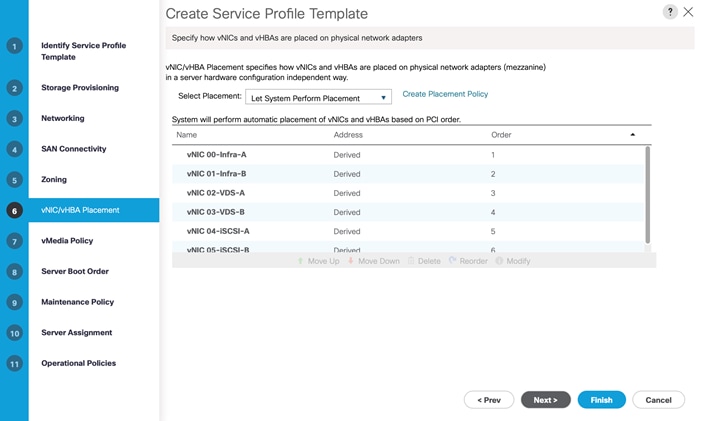
Configure vMedia Policy
1. Do not select a vMedia Policy.
2. Click Next.
Configure Server Boot Order
1. Select Boot-iSCSI-A for Boot Policy.
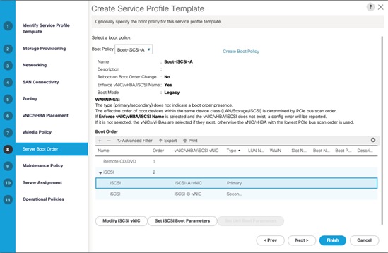
2. In the Boor order, select iSCSI-A-vNIC.
3. Click Set iSCSI Boot Parameters button.
4. In the Set iSCSI Boot Parameters pop-up, leave Authentication Profile to <not set> unless you have independently created one appropriate to your environment.
5. Leave the “Initiator Name Assignment” dialog box <not set> to use the single Service Profile Initiator Name defined in the previous steps.
6. Set iSCSI-initiator-A as the “Initiator IP address Policy.”
7. Select iSCSI Static Target Interface option.
8. Click Add.
9. In the Create iSCSI Static Target dialog box, add the iSCSI target node name for Node 1 (IQN) from Table 25
10. Enter the IP address of Node 1 iSCSI-A interface from Table 24 .
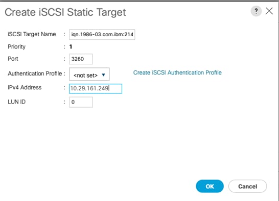
11. Click OK to add the iSCSI Static Target.
12. Keep the iSCSI Static Target Interface option selected and click Add.
13. In the Create iSCSI Static Target dialog box, add the iSCSI target node name for Node 2 (IQN) from Table 25
14. Enter the IP address of Node 2 iSCSI-A interface from Table 24 .
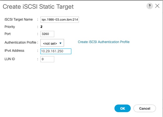
15. Click OK to add the iSCSI Static Target.
16. Verify both the targets on iSCSI Path A as shown below:
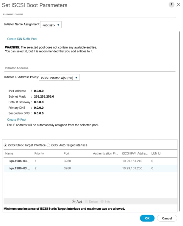
17. Click OK to set the iSCSI-A-vNIC iSCSI Boot Parameters.
18. In the Boor order, select iSCSI-B-vNIC.
19. Click Set iSCSI Boot Parameters button.
20. In the Set iSCSI Boot Parameters pop-up, leave Authentication Profile to <not set> unless you have independently created one appropriate to your environment.
21. Leave the “Initiator Name Assignment” dialog box <not set> to use the single Service Profile Initiator Name defined in the previous steps.
22. Set iSCSI-initiator-B as the “Initiator IP address Policy”.
23. Select iSCSI Static Target Interface option.
24. Click Add.
25. In the Create iSCSI Static Target dialog box, add the iSCSI target node name for Node 1 (IQN) from Table 25
26. Enter the IP address of Node 1 iSCSI-B interface from Table 24 .
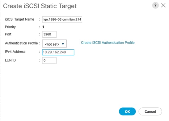
27. Click OK to add the iSCSI Static Target.
28. Keep the iSCSI Static Target Interface option selected and click Add.
29. In the Create iSCSI Static Target dialog box, add the iSCSI target node name for Node 2 (IQN) from Table 25
30. Enter the IP address of Node 2 iSCSI-B interface from Table 24 .
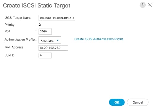
31. Click OK to add the iSCSI Static Target.
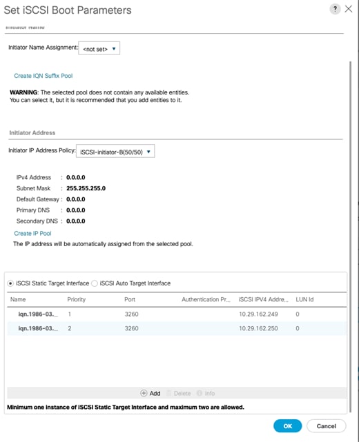
32. Click OK to set the iSCSI-B-vNIC ISCSI Boot Parameters.
33. Click Next to continue to the next section.
Configure Maintenance Policy
To configure the maintenance policy, follow these steps:
1. Change the Maintenance Policy to default.
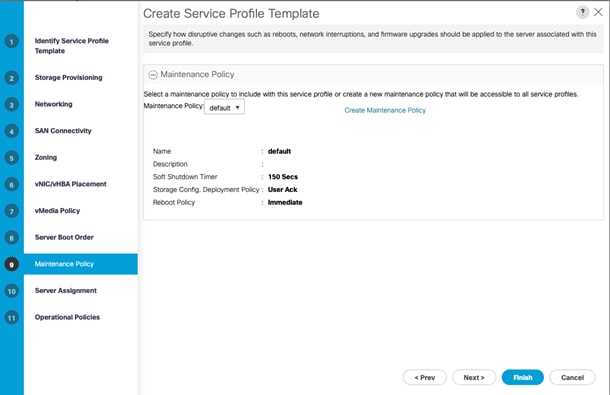
2. Click Next.
Configure Server Assignment
To configure server assignment, follow these steps:
1. In the Pool Assignment list, select Infra-Server-Pool.
2. Optional: Select a Server Pool Qualification policy.
3. Select Down as the power state to be applied when the profile is associated with the server.
4. Optional: Select “UCS-B200M5” for the Server Pool Qualification.
![]() Keep Firmware Management as-is since it will use the default from the Host Firmware list.
Keep Firmware Management as-is since it will use the default from the Host Firmware list.
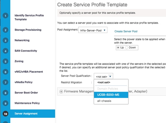
5. Click Next.
Configure Operational Policies
To configure the operational policies, follow these steps:
1. In the BIOS Policy list, select Infra-Host-BIOS.
2. Expand Power Control Policy Configuration and select No-Power-Cap in the Power Control Policy list.
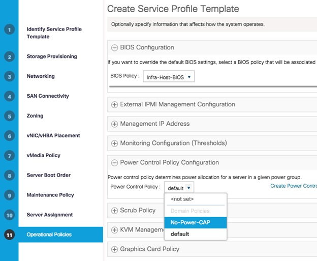
3. Click Finish to create the service profile template.
4. Click OK in the confirmation message.
Create iSCSI Boot Service Profiles
To create service profiles from the service profile template, follow these steps:
1. Connect to the UCS 6454 Fabric Interconnect UCS Manager, click the Servers tab in the navigation pane.
2. Select Service Profile Templates > root > Service Template Infra-ESXi-iSCSI-Host.
3. Right-click Infra-ESXi-iSCSI-Host and select Create Service Profiles from Template.
4. Enter Infra-ESXi-iSCSI-Host-0 for iSCSI deployment as the service profile prefix
5. Enter 1 as the Name Suffix Staring Number.
6. Enter the Number of servers to be deploy in the Number of Instances field.
7. Click OK to create the service profile.
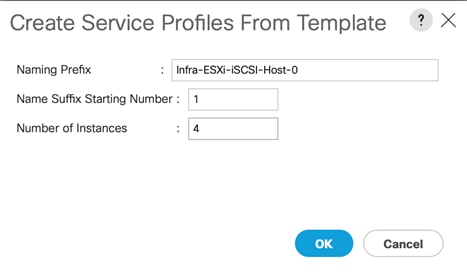
7. Click OK in the confirmation message to provision four VersaStack Service Profiles.
![]() Adjust the number of Service Profile instances based on the actual customer deployment with intended number of VMware ESXi servers needed.
Adjust the number of Service Profile instances based on the actual customer deployment with intended number of VMware ESXi servers needed.
Backup the Cisco UCS Manager Configuration
It is recommended to backup the Cisco UCS Configuration. For additional information, go to:
![]() Refer to the Appendix for example backup procedures
Refer to the Appendix for example backup procedures
Add Servers
Additional server pools, service profile templates, and service profiles can be created under root or in organizations under the root. All the policies at the root level can be shared among the organizations. Any new physical blades can be added to the existing or new server pools and associated with the existing or new service profile templates.
Gather Necessary IQN Information
After the Cisco UCS service profiles have been created, each infrastructure blade in the environment will be assigned certain unique configuration parameters. To proceed with the SAN configuration, this deployment specific information must be gathered from each Cisco UCS blade. Follow these steps:
1. To gather the vNIC IQN information, launch the Cisco UCS Manager GUI. In the navigation pane, click the Servers tab. Expand Servers > Service Profiles > root.
2. Click each service profile and then click the “iSCSI vNICs” tab on the right. Note “Initiator Name” displayed at the top of the page under “Service Profile Initiator Name.”
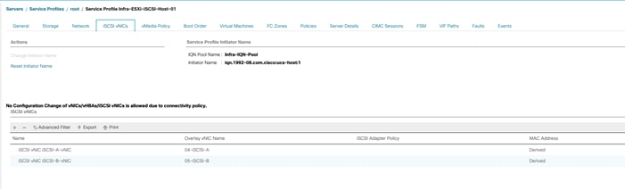
| Cisco UCS Service Profile Name |
iSCSI IQN |
| Infra-ESXi-iSCSI-Host-01 |
iqn.1992-08.com.cisco:ucs-host____ |
| Infra-ESXi-iSCSI-Host-02 |
iqn.1992-08.com.cisco:ucs-host____ |
| Infra-ESXi-iSCSI-Host-03 |
iqn.1992-08.com.cisco:ucs-host____ |
| Infra-ESXi—iSCSI-Host-04 |
iqn.1992-08.com.cisco:ucs-host____ |
As part of IBM FS9100 storage configuration, follow these steps:
1. Create ESXi boot Volumes (Boot LUNs for all the ESXi hosts).
2. Create Share Storage Volumes (for hosting VMFS Datastores).
3. Map Volumes to Hosts.
Table 29 List of Volumes for iSCSI on IBM FS9100*
| Volume Name |
Capacity (GB) |
Purpose |
Mapping |
| Infra-ESXi-iSCSI-Host-01 |
10 |
Boot LUN for the Host |
Infra-ESXi-iSCSI-Host-01 |
| Infra-ESXi-iSCSI-Host-02 |
10 |
Boot LUN for the Host |
Infra-ESXi-iSCSI-Host-02 |
| Infra-ESXi-iSCSI-Host-03 |
10 |
Boot LUN for the Host |
Infra-ESXi-iSCSI-Host-03 |
| Infra-ESXi-iSCSI-Host-04 |
10 |
Boot LUN for the Host |
Infra-ESXi-iSCSI-Host-04 |
| Infra-iSCSI-datastore-1 |
2000** |
Shared volume to host VMs |
All ESXi hosts: Infra-ESXi-iSCSI-Host-01 to Infra-ESXi-iSCSI-Host-04 |
| Infra-iSCSI-datastore-2 |
2000** |
Shared volume to host VMs |
All ESXi hosts: Infra-ESXi-iSCSI-Host-01 to Infra-ESXi-iSCSI-Host-04 |
| Infra-iSCSI-swap |
500** |
Shared volume to host VMware VM swap directory |
All ESXi hosts: Infra-ESXi-iSCSI-Host-01 to Infra-ESXi-iSCSI-Host-04 |
* You should adjust the names and values used for server and volumes names based on their deployment
** The volume size can be adjusted based on customer requirements
Create Volumes on the Storage System
To create volumes on the storage system, follow these steps:
1. Log into the IBM FS9100 GUI and select the Volumes icon on the left screen and select Volumes.
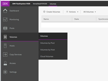
![]() You will repeat the following steps to create and map the volumes shown in Table 29 .
You will repeat the following steps to create and map the volumes shown in Table 29 .
2. Click Create Volumes as shown below.
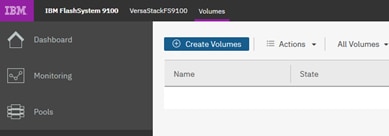
3. Click Basic and then select the pool (VS-Pool0 in this example) from the drop-down list.
4. When creating single volumes, input quantity 1 and the capacity and name from Table 29 . Select Thin-provisioned for Capacity savings and enter the Name of the volume. Select I/O group io_grp0.
5. When creating multiple volumes in bulk enter the quantity required and review the Name field. The number value will be appended to the specified volume name.
![]() IBM FS9100 and Spectrum Virtualize is optimized for environments with more than 30 volumes. Consider distributing Virtual Machines over multiple VMFS datastores for optimal performance.
IBM FS9100 and Spectrum Virtualize is optimized for environments with more than 30 volumes. Consider distributing Virtual Machines over multiple VMFS datastores for optimal performance.
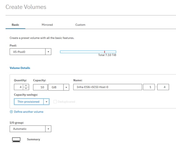
6. Click Create.
![]() During the volume creation, expand view more details to monitor the CLI commands utilized to create each volume. All commands run against the system by either the GUI or CLI will be stored in the Audit log, along with the associated user account and timestamp.
During the volume creation, expand view more details to monitor the CLI commands utilized to create each volume. All commands run against the system by either the GUI or CLI will be stored in the Audit log, along with the associated user account and timestamp.
7. Repeat steps 1-6 to create all the required volumes and verify all the volumes have successfully been created as shown in the sample output below.
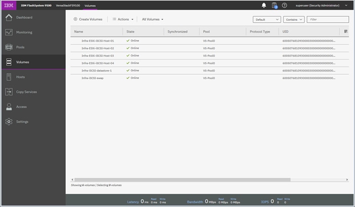
Create Host Cluster and Host Objects
Host Cluster Shared and Private Mappings
In traditional hypervisor environments such as VMware vSphere, each physical host requires access to the same shared datastores (or LUNs) in order to facilitate features such as vMotion, High Availability and Fault Tolerance. It is import for all ESXi hosts within a vSphere cluster to have identical access to LUNs presented from the FS9100.
The Host Clusters feature in IBM Spectrum Virtualize products introduces a way to simplify administration when mapping volumes to host environments that require shared storage.
![]() It is recommended that a Host Cluster object be created for each vSphere Cluster visible in vCenter, and any ESXi hosts within the vSphere cluster be defined as individual host objects within FS9100. This ensures that volume access is consistent across all members of the cluster and any hosts that are subsequently added to the Host Cluster will inherit the same LUN mappings.
It is recommended that a Host Cluster object be created for each vSphere Cluster visible in vCenter, and any ESXi hosts within the vSphere cluster be defined as individual host objects within FS9100. This ensures that volume access is consistent across all members of the cluster and any hosts that are subsequently added to the Host Cluster will inherit the same LUN mappings.
To create host clusters and objects, follow these steps:
1. Click Hosts then click Host Clusters.
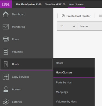
2. Click Create Host Cluster.
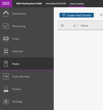
3. Give the Host Cluster a friendly name.
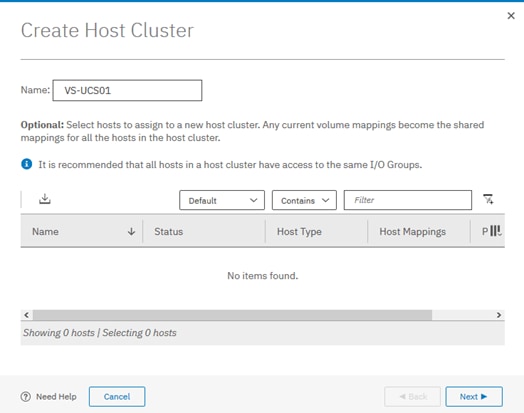
4. Review the summary and click Make Host Cluster.
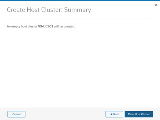
Add Hosts to Host Cluster
Create iSCSI Host Definitions
To create iSCSI host definitions, follow these steps:
1. Click Hosts and then Hosts from the navigation menu.
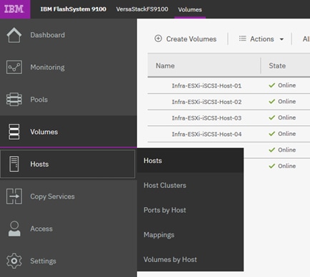
2. For each ESXi host (Table 28 ), follow these steps on the IBM FS9100 system:
a. Click Add Host.
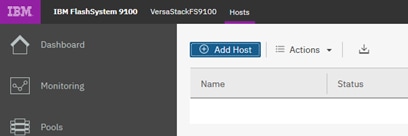
b. Select iSCSI or iSER (SCSI) Host. Add the name of the host to match the ESXi service profile name from Table 29 . Type the IQN corresponding to the ESXi host from Table 28 and select the Host Cluster that we created in the previous step.
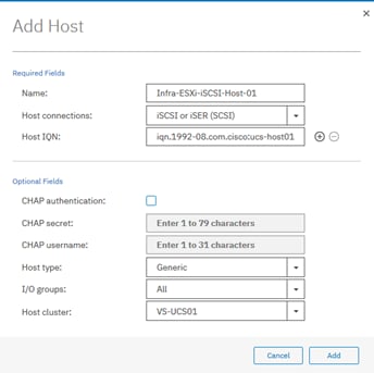
3. Click Add.
Map Volumes to Hosts and Host Cluster
To map volumes to hosts and clusters, follow these steps:
1. Now the Host Cluster and Host objects have been created, you need to map each LUN to the hosts.
2. Click Volumes.
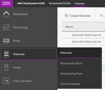
3. Right-click the Boot LUN for each ESXi host in turn and choose Map to Host.
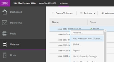
4. Select the Hosts radio button, and select the corresponding Host in the list and click Next
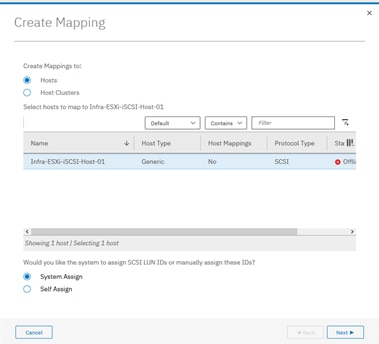
5. Click Map Volumes and when the process is complete, click Close.
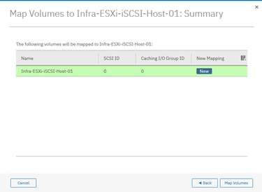
6. Repeat steps 1-5 to map a Boot volume for each ESXi host in the cluster.
7. When mapping shared volumes from Table 29 , such as for shared VMFS datastores, right-click the volume in question (or select multiple volumes if mapping multiple LUNs) and select Map to Host or Host Cluster.
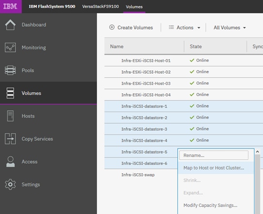
8. Select the Host Clusters radio button.
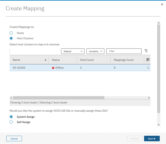
9. Review the summary and Click Map Volumes to confirm.
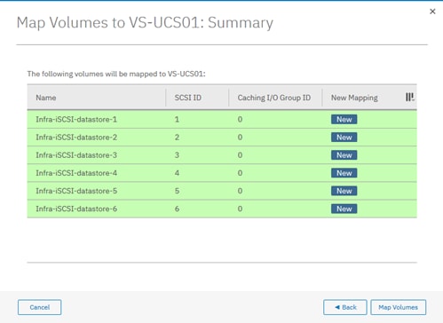
10. Any Shared host cluster mappings will be automatically inherited by any future ESXi hosts which are defined as members of the host cluster.
VMware ESXi 6.7 U3
This section provides detailed instructions for installing VMware ESXi 6.7 U3 in the VersaStack UCS environment. After the procedures are completed, two booted ESXi hosts will be provisioned to host customer workloads.
Several methods exist for installing ESXi in a VMware environment. These procedures focus on how to use the built-in keyboard, video, mouse (KVM) console and virtual media features in Cisco UCS Manager to map remote installation media to individual servers and connect to their boot logical unit numbers (LUNs).
Log into Cisco UCS Manager
The IP KVM enables the administrator to begin the installation of the operating system (OS) through remote media. It is necessary to log into the UCS environment to run the IP KVM.
To log into the Cisco UCS environment, follow these steps:
1. Open a web browser and enter the IP address for the Cisco UCS cluster. This step launches the Cisco UCS Manager application.
2. Under HTML, click the Launch UCS Manager link.
3. When prompted, enter admin as the username and enter the administrative password.
4. To log in to Cisco UCS Manager, click Login.
5. From the main menu, click the Servers tab.
6. Select Servers > Service Profiles > root > Infra-ESXi-iSCSI-Host-01.
7. Right-click Infra-ESXi-iSCSI-Host-01 and select KVM Console.
8. If prompted to accept an Unencrypted KVM session, accept as necessary.
9. Open KVM connection to all the hosts by right-clicking the Service Profile and launching the KVM console
10. Boot each server by selecting Boot Server and clicking OK. Click OK again.
Install ESXi on the UCS Servers
To install VMware ESXi to the boot LUN of the hosts, follow these steps on each host. The Cisco customer VMware ESXi image can be downloaded from:
https://my.vmware.com/web/vmware/details?downloadGroup=OEM-ESXI67U3-CISCO&productId=742
![]() VMware ESXi will be installed on two Cisco UCS servers as part of the deployment covered in the following sections. The number of ESXi servers can vary based on the customer specific deployment.
VMware ESXi will be installed on two Cisco UCS servers as part of the deployment covered in the following sections. The number of ESXi servers can vary based on the customer specific deployment.
1. In the KVM windows, click Virtual Media in the upper right of the screen.
2. Click Activate Virtual Devices.
3. If prompted to accept an Unencrypted KVM session, accept as necessary.
4. Click Virtual Media and select Map CD/DVD.
5. Browse to the ESXi installer ISO image file and click Open.
6. Click Map Device.
7. Click the KVM tab to monitor the server boot.
8. Reset the server by clicking Reset button. Click OK.
9. Select Power Cycle on the next window and click OK and OK again.
10. From the ESXi Boot Menu, select the ESXi installer.
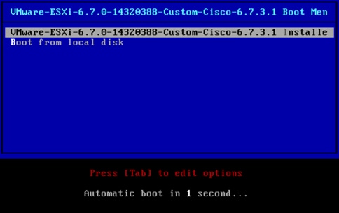
11. After the installer has finished loading, press Enter to continue with the installation.
12. Read and accept the end-user license agreement (EULA). Press F11 to accept and continue.
13. Select the LUN that was previously set up and discovered as the installation disk for ESXi and press Enter to continue with the installation.
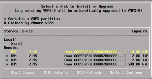
14. Select the appropriate keyboard layout and press Enter.
15. Enter and confirm the root password and press Enter.
16. The installer issues a warning that the selected disk will be repartitioned. Press F11 to continue with the installation.
17. After the installation is complete, press Enter to reboot the server.
18. Repeat the ESXi installation process for all the Service Profiles.
![]() In this deployment, we used two UCS server blades for the VMware vSphere deployment. Additional ESXi servers can be added based on the actual customer deployment.
In this deployment, we used two UCS server blades for the VMware vSphere deployment. Additional ESXi servers can be added based on the actual customer deployment.
Set Up Management Networking for ESXi Hosts
Adding a management network for each VMware host is necessary for managing the host. To add a management network for the VMware hosts, follow these steps on each ESXi host.
To configure the ESXi hosts with access to the management network, follow these steps:
1. After the server has finished post-installation rebooting, press F2 to customize the system.
2. Log in as root, enter the password chosen during the initial setup, and press Enter to log in.
3. Select Troubleshooting Options and press Enter.
4. Select Enable ESXi Shell and press Enter.
5. Select Enable SSH and press Enter.
6. Press Esc to exit the Troubleshooting Options menu.
7. Select the Configure Management Network option and press Enter.
8. Select Network Adapters
9. Select vmnic0 (if it is not already selected) by pressing the Space Bar.
10. Use the arrow keys and spacebar to highlight and select vmnic1.
11. Verify that the numbers in the Hardware Label field match the numbers in the Device Name field.
![]() In lab testing, examples have been seen where the vmnic and device ordering do not match. If this is the case, use the Consistent Device Naming (CDN) to note which vmnics are mapped to which vNICs and adjust the upcoming procedure accordingly.
In lab testing, examples have been seen where the vmnic and device ordering do not match. If this is the case, use the Consistent Device Naming (CDN) to note which vmnics are mapped to which vNICs and adjust the upcoming procedure accordingly.
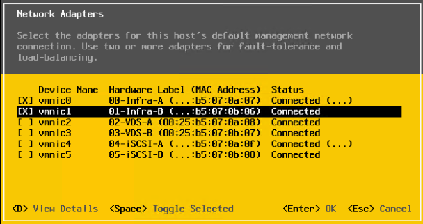
12. Press Enter to save and exit the Network Adapters window.
13. Select the VLAN (Optional) and press Enter.
14. Enter the <IB-Mgmt VLAN> (11) and press Enter.
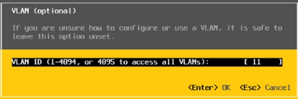
15. Select IPv4 Configuration and press Enter.
16. Select the Set Static IP Address and Network Configuration option by using the Space Bar.
17. Enter the IP address for managing the ESXi host.
18. Enter the subnet mask for the management network of the ESXi host.
19. Enter the default gateway for the ESXi host.
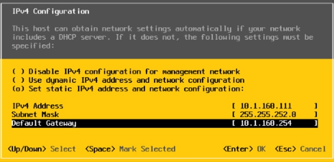
20. Press Enter to accept the changes to the IP configuration.
21. Select the IPv6 Configuration option and press Enter.
22. Using the Space Bar, select Disable IPv6 (restart required) and press Enter.
23. Select the DNS Configuration option and press Enter.
![]() Because the IP address is assigned manually, the DNS information must also be entered manually.
Because the IP address is assigned manually, the DNS information must also be entered manually.
24. Enter the IP address of the primary DNS server.
25. Optional: Enter the IP address of the secondary DNS server.
26. Enter the fully qualified domain name (FQDN) for the ESXi host.
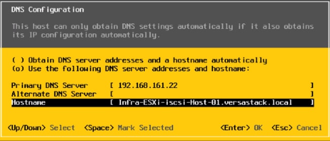
27. Press Enter to accept the changes to the DNS configuration.
28. Press Esc to exit the Configure Management Network submenu.
29. Press Y to confirm the changes and reboot the host.
30. Repeat this procedure for all the ESXi hosts in the setup.
Reset VMware ESXi Host VMkernel Port vmk0 MAC Address (Optional)
By default, the MAC address of the management VMkernel port vmk0 is the same as the MAC address of the Ethernet port it is placed on. If the ESXi host’s boot LUN is remapped to a different server with different MAC addresses, a MAC address conflict will exist because vmk0 will retain the assigned MAC address unless the ESXi System Configuration is reset. To reset the MAC address of vmk0 to a random VMware-assigned MAC address on the ESXi hosts, follow these steps:
1. From the ESXi console menu main screen, type Ctrl-Alt-F1 to access the VMware console command line interface. In the UCSM KVM, Ctrl-Alt-F1 appears in the list of Static Macros.
2. Log in as root.
3. Type esxcfg-vmknic –l to get a detailed listing of interface vmk0. vmk0 should be a part of the “Management Network” port group. Note the IP address and netmask of vmk0.
4. To remove vmk0, type esxcfg-vmknic –d “Management Network”.
5. To re-add vmk0 with a random MAC address, type esxcfg-vmknic –a –i <vmk0-ip> -n <vmk0-netmask> “Management Network”.
6. Verify vmk0 has been re-added with a random MAC address by typing esxcfg-vmknic –l.
7. Tag vmk0 as the management interface by typing esxcli network ip interface tag add -i vmk0 -t Management.
8. When vmk0 was re-added, if a message popped up saying vmk1 was marked as the management interface, type esxcli network ip interface tag remove -i vmk1 -t Management.
9. Type exit to log out of the command line interface.
10. Type Ctrl-Alt-F2 to return to the ESXi console menu interface.
VMware vSphere Configuration
The vSphere configuration covered in this section is common to all the ESXi servers.
Log into VMware ESXi Hosts Using VMware vSphere Client
To log into the ESXi host using the VMware Host Client, follow these steps:
1. Open a web browser on the management workstation and navigate to the management IP address of the host.
2. Click Open the VMware Host Client.
3. Enter root for the user name.
4. Enter the root password configured during the installation process.
5. Click Login to connect.
6. Decide whether to join the VMware Customer Experience Improvement Program and click OK.
7. Repeat this process to log into all the ESXi hosts.
![]() The first host will need to go through the initial configuration using the VMware Host Client if a vCenter Appliance is being installed to the VSI cluster. Subsequent hosts can be configured directly to the vCenter Server after it is installed to the first ESXi host, or all hosts can be configured directly within the vCenter if a pre-existing server is used that is outside of the deployed converged infrastructure.
The first host will need to go through the initial configuration using the VMware Host Client if a vCenter Appliance is being installed to the VSI cluster. Subsequent hosts can be configured directly to the vCenter Server after it is installed to the first ESXi host, or all hosts can be configured directly within the vCenter if a pre-existing server is used that is outside of the deployed converged infrastructure.
Set Up VMkernel Ports and Virtual Switch
To set up the VMkernel ports and the virtual switches on all the ESXi hosts, follow these steps:
1. From the Host Client, select Networking within the Navigator window on the left.
2. In the center pane, select the Port groups tab.
3. Right-click the VM Network port group and select the Remove option.
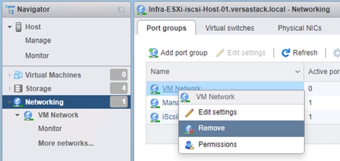
4. Right-click the Management Network and select Edit Settings.
5. Expand NIC teaming and select vmnic1 within the Failover order section.
6. Click on the Mark standby option.
7. Click Save.
8. Click on the Add port group option.
9. Name the port group IB-Mgmt.
10. Set the VLAN ID to <<IB-Mgmt VLAN ID>>.
11. Click Add.
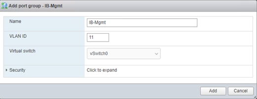
12. Right-click the IB-Mgmt port group and select the Edit Settings option.
13. Expand NIC teaming and select Yes within the Override failover order section.
14. Select vmnic1 within the Failover order section.
15. Click on the Mark standby option.
16. Click Save.
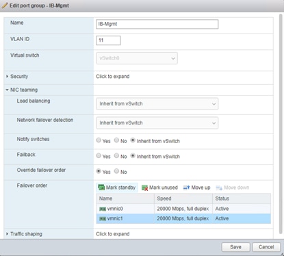
17. In the center pane, select the Virtual switches tab.
18. Right-click vSwitch0 and select Edit settings.
19. Change the MTU to 9000.
20. Expand NIC teaming and highlight vmnic1. Select Mark active.
21. Click Save.
22. Select the VMkernel NICs tab in the center pane.
23. Select Add VMkernel NIC.
24. Enter vMotion within the New port group section.
25. Set the VLAN ID to <<vMotion VLAN ID>>
26. Change the MTU to 9000.
27. Click on the Static option within IPv4 settings and expand the section.
28. Enter the Address and Subnet mask to be used for the ESXi vMotion IP.
29. Change the TCP/IP stack to vMotion stack.
30. Click Create.
![]() Optionally, with 40GE vNICs, you can create two additional vMotion VMkernel NICs in the same subnet and VLAN to take advantage of the bandwidth. These will need to be in new dedicated port groups for the new vMotion VMkernels.
Optionally, with 40GE vNICs, you can create two additional vMotion VMkernel NICs in the same subnet and VLAN to take advantage of the bandwidth. These will need to be in new dedicated port groups for the new vMotion VMkernels.
31. Re-select the Port groups tab.
32. Right-click the vMotion port group and select the Edit settings option.
33. Expand the NIC Teaming section and select Yes for Override failover order.
34. Highlight vmnic0 and select Mark standby.
35. Highlight vmnic1 and select Mark active.
36. Click Save.
37. Repeat steps 32-36 if additional vMotion port groups were created.
To add the iSCSI networking configuration on the first ESXi host, follow the steps below. In this section, a single iSCSI Boot vSwitch is configured with two uplinks, one to UCS fabric A and the other to fabric B. The first VMkernel port will be mapped only to the fabric A uplink and the second one will be mapped to the fabric B uplink.
1. From the Host Client, select Networking.
2. In the center pane, select the Virtual switches tab.
3. Highlight the iScsiBootvSwitch line.
4. Select Edit settings.
5. Change the MTU to 9000.
6. Select Add uplink to add an uplink to iScsiBootvSwitch.
7. Use the pulldown to select vmnic5 for Uplink 2.
8. Expand NIC teaming, select vmnic5, and select Mark standby.
9. Click Save.
10. Select the VMkernel NICs tab.
11. Select the vmk1 iScsiBootPG row. Select Edit Settings to edit the properties of this VMkernel port.
12. Change the MTU to 9000.
13. Expand IPv4 Settings and enter a unique IP address in the iSCSI-A subnet but outside of the Cisco UCS iSCSI-IP-Pool-A.
![]() It is recommended to enter a unique IP address for this VMkernel port to avoid any issues related to IP Pool reassignments.
It is recommended to enter a unique IP address for this VMkernel port to avoid any issues related to IP Pool reassignments.
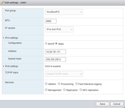
14. Click Save to save the changes to the VMkernel port.
15. Select the Port groups tab.
16. Select the iScsiBootPG row. Select Edit Settings to edit the properties of this port group.
17. Expand NIC teaming and select Yes to the right of Override failover order.
18. Select vmnic5 and select Mark unused.
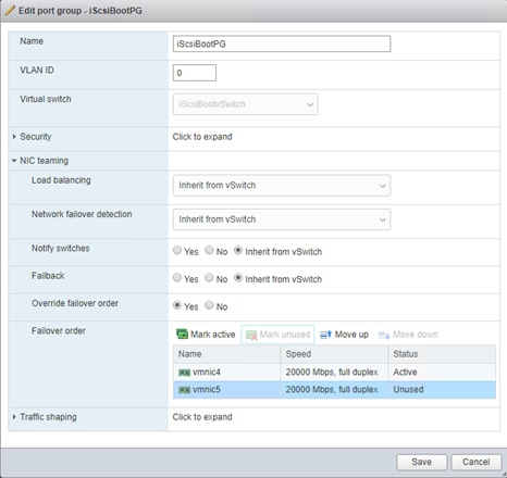
19. Click Save to complete the changes to the iScsiBootPG.
20. At the top, select the Virtual switches tab.
21. Select the iScsiBootvSwitch row and click Edit settings.
22. Expand NIC teaming and select vmnic5. Select Mark active to make vmnic5 active within the vSwitch.
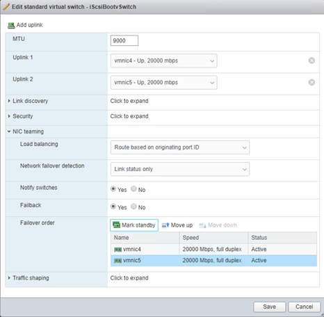
23. Click Save to save the changes to the vSwitch.
24. At the top, select the VMkernel NICs tab.
25. Click Add VMkernel NIC.
26. For New port group, enter iScsiBootPG-B
27. For Virtual switch, select iScsiBootvSwitch.
28. Leave the VLAN ID set at 0.
29. Change the MTU to 9000.
30. Select Static IPv4 settings and expand IPv4 settings.
31. Enter a unique IP address and netmask in the iSCSI-B subnet but outside of the Cisco UCS iSCSI-IP-Pool-B.
![]() It is recommended to enter a unique IP address for this VMkernel port to avoid any issues related to IP Pool reassignments.
It is recommended to enter a unique IP address for this VMkernel port to avoid any issues related to IP Pool reassignments.
32. Do not select any of the Services.
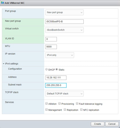
33. Click Create.
34. Select the Port groups tab.
35. Select the iScsiBootPG-B row. Select Edit Settings to edit the properties of this port group.
36. Expand NIC teaming and select Yes to the right of Override failover order.
37. To the right of Failover order, select vmnic4 and select Mark unused.
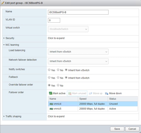
Setup iSCSI Multipathing
To setup the iSCSI multipathing on the ESXi hosts, follow these steps:
1. From each Host Client, select Storage on the left.
2. In the center pane select the Adapters tab.
3. Select the iSCSI software adapter and click Configure iSCSI.
4. Under Dynamic targets, click Add dynamic target.
5. Enter the IP Address of IBM FS9100 Node1 iSCSI ethernet Port 5 and press Enter.
6. Repeat putting the IP address of Node1 Port6, Node2 Port5, Node2 Port6.
7. Click Save configuration.
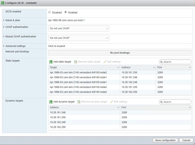
8. Click Cancel to close the window.
Mount Required Datastores
In the procedure below, three shared datastores, two for hosting the VMs and another to host the VM swap files, will be mounted to all the ESXi servers. Customers can adjust the number and size of the shared datastores based on their particular deployments.
To mount the required datastores, follow these steps on each ESXi host:
1. From the Host Client, select Storage.
2. In the center pane, select the Datastores tab.
3. In the center pane, select New Datastore to add a new datastore.
4. In the New datastore popup, select Create new VMFS datastore.
5. Click Next.
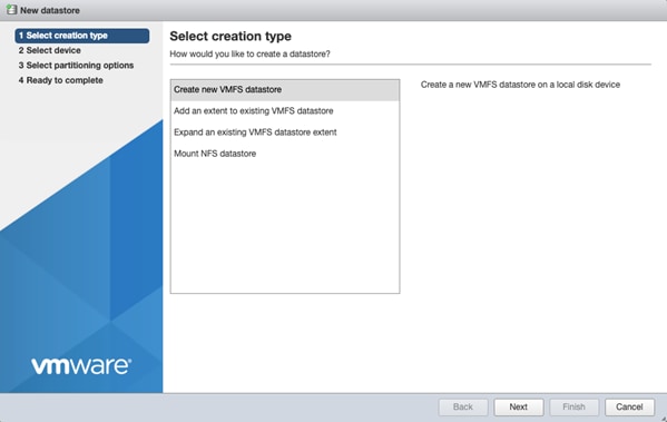
6. Enter Infra_datastore1 as the datastore name.
7. Verifying by using the size of the datastore LUN, select the LUN configured for VM hosting and click Next.
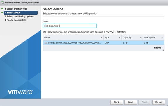
8. Accept default VMFS setting and Use full disk option to retain maximum available space.
9. Click Next
10. Verify the details and Click Finish.
11. In the center pane, select the Datastores tab.
12. In the center pane, select New Datastore to add a new datastore.
13. In the New datastore popup, select Create new VMFS datastore.
14. Click Next.
15. Enter Infra_datastore2 as the datastore name.
16. Verifying by using the size of the datastore LUN, select the LUN configured for VM hosting and click Next.
17. Accept default VMFS setting and Use full disk option to retain maximum available space.
18. Click Next
19. Verify the details and Click Finish.
20. In the center pane, select the Datastores tab.
21. In the center pane, select New Datastore to add a new datastore.
22. In the New datastore popup, select Create new VMFS datastore.
23. Click Next.
24. Enter Infra_swap as the datastore name.
25. Verifying by using the size of the datastore LUN, select the LUN configured for VM hosting and click Next.
26. Accept default VMFS setting and Use full disk option to retain maximum available space.
27. Click Next
28. Verify the details and Click Finish.
29. The storage configuration should look similar to figure shown below.
30. Repeat steps 1-29 on all the ESXi hosts.
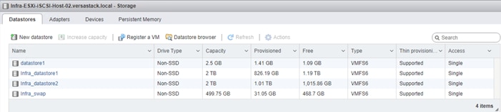
Configure NTP on ESXi Hosts
To configure NTP on the ESXI hosts, follow these steps on each host:
1. From the Host Client, select Manage.
2. In the center pane, select Time & date.
3. Click Edit settings.
4. Make sure Use Network Time Protocol (enable NTP client) is selected.
5. Use the drop-down to select Start and stop with host.
6. Enter the NTP addresses in the NTP servers box separated by a comma, Nexus switch addresses can be entered if NTP service is configured on the switches.
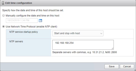
7. Click Save to save the configuration changes.
8. Select Actions > NTP service > Start.
9. Verify that NTP service is now running and the clock is now set to approximately the correct time.
![]() The NTP server time may vary slightly from the host time.
The NTP server time may vary slightly from the host time.
Move VM Swap File Location
To move the VM swap file location, follow these steps on each ESXi host:
1. From the Host Client, select Manage.
2. In the center pane, select Swap.
3. Click Edit settings.
4. Use the drop-down list to select Infra_swap. Leave all other settings unchanged.
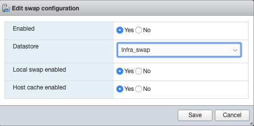
5. Click Save to save the configuration changes.
Install VMware Drivers for the Cisco Virtual Interface Card (VIC)
For the most recent versions, please refer to Cisco UCS HW and SW Availability Interoperability Matrix. If a more recent driver is made available that is appropriate for VMware vSphere 6.7 U3, download and install the latest drivers.
To install VMware VIC Drivers on the ESXi hosts using esxcli, follow these steps:
1. Download and extract the following VIC Drivers to the Management workstation:
NFNIC Driver version 4.0.0.40:
https://my.vmware.com/web/vmware/details?downloadGroup=DT-ESXI67-CISCO-NFNIC-40040&productId=742
NENIC Driver version 1.0.29.0:
https://my.vmware.com/web/vmware/details?downloadGroup=DT-ESXI67-CISCO-NENIC-10290&productId=742
To install VIC Drivers on ALL the ESXi hosts, follow these steps:
1. From each Host Client, select Storage.
2. Right-click datastore1 and select Browse.
3. In the Datastore browser, click Upload.
4. Navigate to the saved location for the downloaded VIC drivers and select VMW-ESX-6.7.0-nenic-1.0.29.0-offline_bundle-12897497.zip.
5. In the Datastore browser, click Upload.
6. Navigate to the saved location for the downloaded VIC drivers and select VMW-ESX-6.7.0-nfnic-4.0.0.40-offline_bundle-14303978.zip.
7. Click Open to upload the file to datastore1.
8. Make sure the file has been uploaded to both ESXi hosts.
9. Place each host into Maintenance mode if it isn’t already.
10. Connect to each ESXi host through ssh from a shell connection or putty terminal.
11. Login as root with the root password.
12. Run the following commands on each host:
esxcli software vib update -d /vmfs/volumes/datastore1/VMW-ESX-6.7.0-nenic-1.0.29.0-offline_bundle-12897497.zip
esxcli software vib update -d /vmfs/volumes/datastore1/VMW-ESX-6.7.0-nfnic-4.0.0.40-offline_bundle-14303978.zip
reboot
13. Log into the Host Client on each host once reboot is complete and exit Maintenance Mode.
Deploy VMware vCenter Appliance 6.7 (Optional)
The VCSA deployment consists of 2 stages: install and configuration. To build the VMware vCenter virtual machine, follow these steps:
1. Download the VCSA ISO from VMware at https://my.vmware.com/group/vmware/details?productId=742&rPId=35624&downloadGroup=VC67U3
2. Using ISO mounting software, mount the ISO image as a disk on the management workstation. (For example, with the Mount command in Windows Server 2012).
3. In the mounted disk directory, navigate to the vcsa-ui-installer > win32 directory and double-click installer.exe. The vCenter Server Appliance Installer wizard appears.
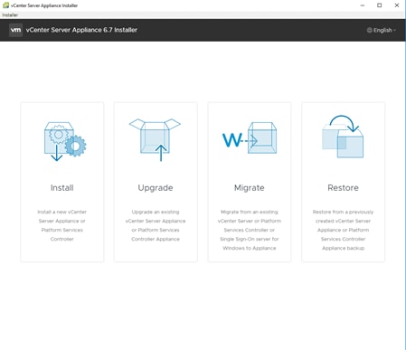
4. Click Install to start the vCenter Server Appliance deployment wizard.
5. Click Next in the Introduction section.
6. Read and accept the license agreement and click Next.
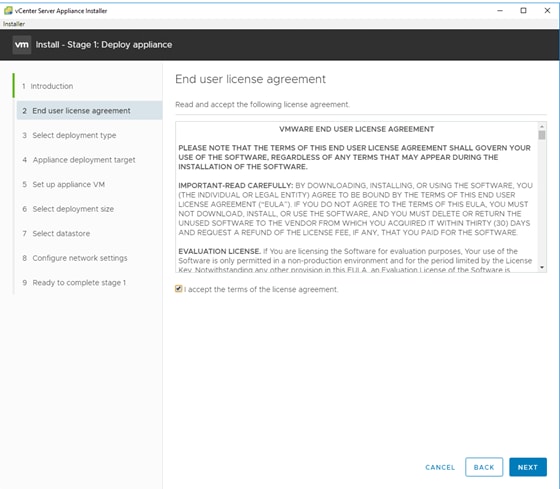
7. In the “Select deployment type” section, select vCenter Server with an Embedded Platform Services Controller and click Next.
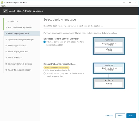
8. In the “Appliance deployment target”, enter the ESXi host name or IP address for the first configured ESXi host, User name and Password. Click Next.
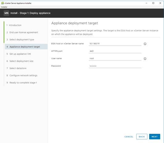
9. Click Yes to accept the certificate.
10. Enter the Appliance name and password details in the “Set up appliance VM” section. Click Next.
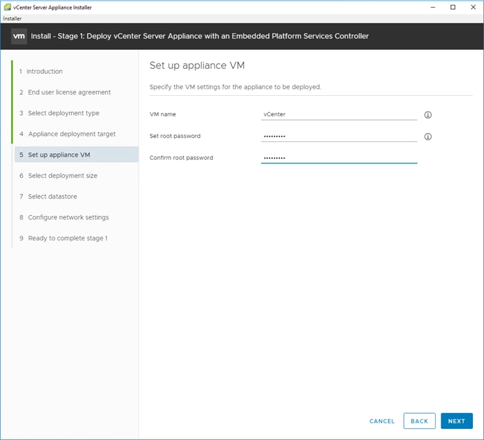
11. In the “Select deployment size” section, Select the deployment size and Storage size. For example, “Tiny” Deployment size was selected in this CVD.
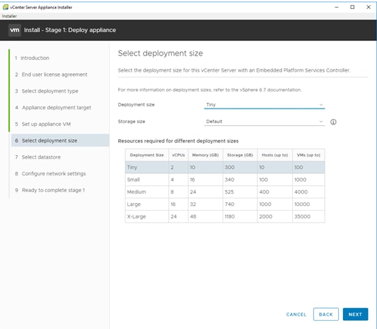
12. Click Next.
13. Select preferred datastore e.g. the “Infra_datastore1” that was created previously.
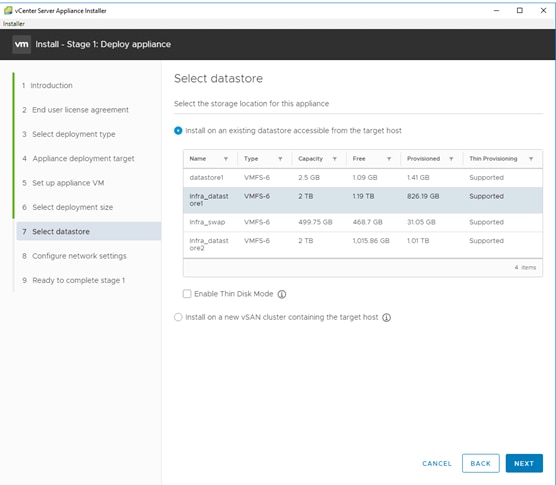
14. Click Next.
15. In the “Network Settings” section, configure the following settings:
a. Choose a Network: VM Network
c. IP version: IPV4
d. IP assignment: static
e. System name: <vcenter-fqdn> (optional)
f. IP address: <vcenter-ip>
g. Subnet mask or prefix length: <vcenter-subnet-mask>
h. Default gateway: <vcenter-gateway>
i. DNS Servers: <dns-server>
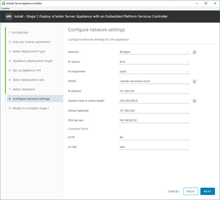
16. Click Next.
17. Review all values and click Finish to complete the installation.
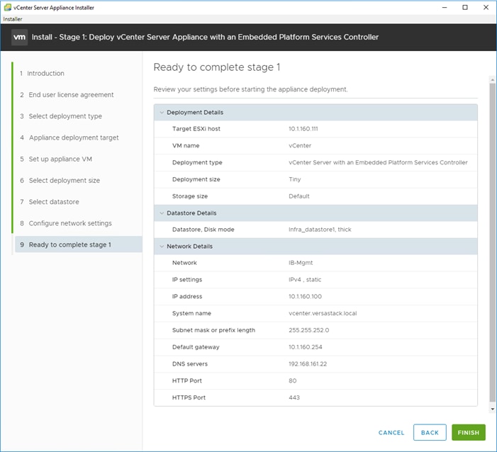
18. The vCenter appliance installation will take a few minutes to complete.
19. Click Continue to proceed with stage 2 configuration.
20. Click Next.
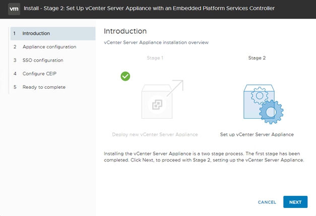
21. In the Appliance Configuration, configure the below settings:
a. Time Synchronization Mode: Synchronize time with the ESXi host.
![]() Since the ESXi host has been configured to synchronize the time with an NTP server, vCenter time can be synced to ESXi host. Customer can choose a different time synchronization setting.
Since the ESXi host has been configured to synchronize the time with an NTP server, vCenter time can be synced to ESXi host. Customer can choose a different time synchronization setting.
b. SSH access: Enabled.
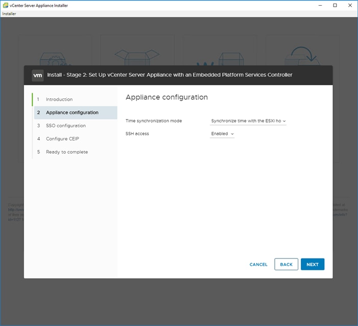
22. Click Next.
23. Complete the SSO configuration as shown below.
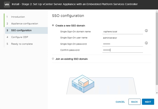
24. Click Next.
25. If preferred, select Join the VMware’s Customer Experience Improvement Program (CEIP).
26. Click Next.
27. Review the configuration and click Finish.
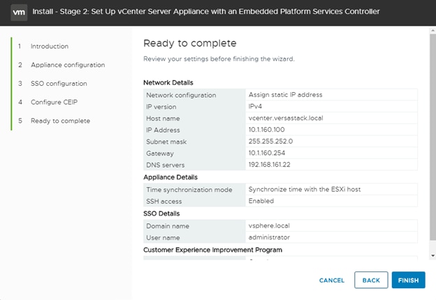
28. Click OK.
29. Make note of the access URL shown in the completion screen.
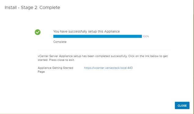
30. Click Close.
Adjust vCenter CPU Settings (Optional)
If a vCenter deployment size of Small or larger was selected in the vCenter setup, it is possible that the VCSA’s CPU setup does not match the UCS server CPU hardware configuration. Cisco UCS B200 and C220 servers are 2-socket servers. If the Small or larger deployment size was selected and vCenter was setup for a 4-socket server or more, the setup will cause issues in the VMware ESXi cluster Admission Control. To resolve the Admission Control issue, follow these steps:
1. Open a web browser on the management workstation and navigate to the Infra-esxi-host-01 management IP address.
2. Click Open the VMware Host Client.
3. Enter root for the user name.
4. Enter the root password.
5. Click Login to connect.
6. In the center pane, right-click the vCenter VM and select Edit settings.
7. In the Edit settings window, expand CPU and check the value of Sockets is not greater than 2.
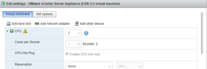
8. If the number of Sockets is greater than 2, it will need to be adjusted. Click Cancel.
9. If the number of Sockets needs to be adjusted:
10. Right-click the vCenter VM and select Guest OS > Shut down. Click Yes on the confirmation.
11. Once vCenter is shut down, right-click the vCenter VM and select Edit settings.
12. In the Edit settings window, expand CPU and change the Cores per Socket value to make the Sockets value 2.
13. Click Save.
14. Right-click the vCenter VM and select Power > Power on. Wait approximately 10 minutes for vCenter to come up.
Set Up VMware vCenter Server
To setup the VMware vCenter Server, follow these steps:
1. Using a web browser, navigate to https://<vcenter-ip>/vsphere-client. You will need to navigate security screens.
2. Select LAUNCH VSPHERE CLIENT (HTML5).
![]() Although previous versions of this document used FLEX vSphere Web Client, the VMware vSphere HTML5 Client is fully featured in vSphere 6.7U2 and will be used going forward.
Although previous versions of this document used FLEX vSphere Web Client, the VMware vSphere HTML5 Client is fully featured in vSphere 6.7U2 and will be used going forward.
3. Log in using the Single Sign-On username (administrator@vsphere.local) and password created during the vCenter installation.
Setup Data Center, Cluster, DRS and HA for ESXi Nodes
If a new data center is needed for the VersaStack, follow these steps on the vCenter:
1. Connect to the vSphere HTML5 Client and click Hosts and Clusters from the left side Navigator window or the Hosts and Clusters icon from the Home center window
2. From Hosts and Clusters:
3. Right-click the vCenter icon and from the drop-down list select New Datacenter.
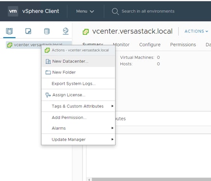
4. From the New Datacenter pop-up dialogue enter in a Datacenter name and click OK.
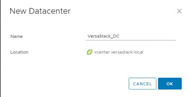
Add the VMware ESXi Hosts
To add the VMware ESXi Hosts using the VMware vSphere Web Client, follow these steps:
1. From the Hosts and Clusters tab, right-click the new or existing Datacenter within the Navigation window, and from the drop-down list select New Cluster.
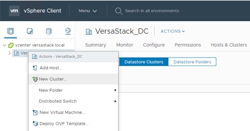
2. Enter a name for the new cluster, select the DRS and HA checkmark boxes, leaving all other options with defaults.
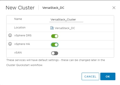
3. Click OK to create the cluster.
![]() If mixing Cisco UCS B or C-Series M2, M3 or M4 servers within a vCenter cluster, it is necessary to enable VMware Enhanced vMotion Compatibility (EVC) mode. For more information about setting up EVC mode, refer to Enhanced vMotion Compatibility (EVC) Processor Support.
If mixing Cisco UCS B or C-Series M2, M3 or M4 servers within a vCenter cluster, it is necessary to enable VMware Enhanced vMotion Compatibility (EVC) mode. For more information about setting up EVC mode, refer to Enhanced vMotion Compatibility (EVC) Processor Support.
4. Click OK to create the cluster.
5. Expand “VersaStack_DC”.
6. Right-click “VersaStack_Cluster” and select Settings.
7. Select Configure > General in the list and select Edit to the right of General.

8. Select Datastore specified by host and click OK.
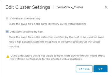
9. Right-click the newly created cluster and from the drop-down list select the Add Host.
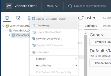
10. Enter the IP or FQDN of the ESXi hosts that needs to be added to the cluster and click Next.
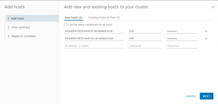
11. Enter root for the User Name, provide the password set during initial setup and click Next.
12. Click Yes in the Security Alert pop-up to confirm the host’s certificate. (check the upper box and click OK)
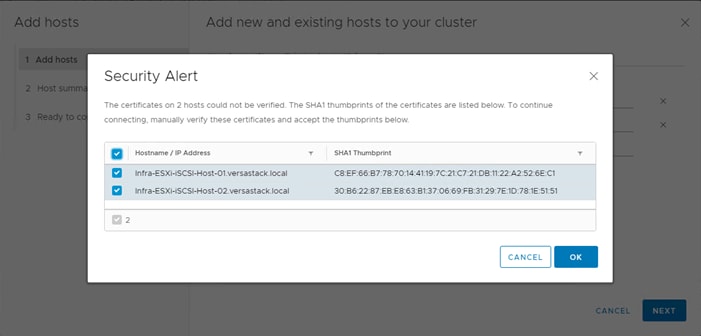
13. Click Next past the Host summary dialogue. (Ignore the warning about the powered on VM, it’s the vCenter).
14. Review the host FQDN or IP address details getting added to the cluster and click Finish.
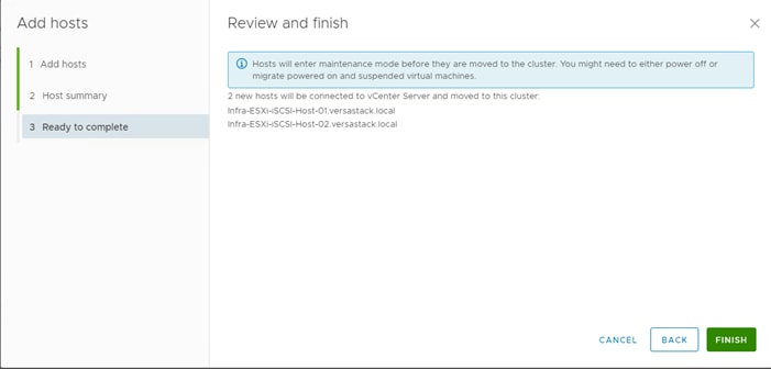
15. In vSphere, in the left pane right-click the newly created cluster, and under Storage click Rescan Storage.
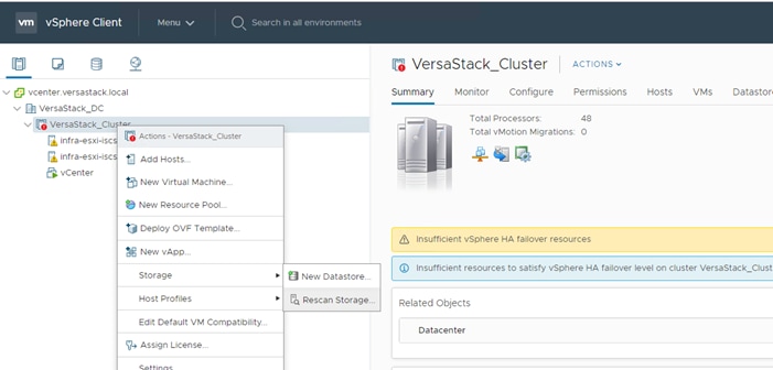
16. Click OK on the Rescan Storage popup window.
ESXi Dump Collector Setup for iSCSI Hosts
ESXi hosts booted with iSCSI need to be configured with ESXi dump collection. The Dump Collector functionality is supported by the vCenter but is not enabled by default on the vCenter Appliance.
![]() Make sure the account used to login is Administrator@vsphere.local (or a system admin account).
Make sure the account used to login is Administrator@vsphere.local (or a system admin account).
To setup the ESXi dump collector for iSCSI hosts, follow these steps:
1. In the vSphere web client, select Home from Menu drop down tab on the top.
2. Select Administration in the left panel.
3. Click System Configuration.
4. In the left-hand pane, select Services and select VMware vSphere ESXi Dump Collector.
5. In the Actions menu, choose Start.
6. In the Actions menu, click Edit Startup Type.
7. Select Automatic.
8. Click OK.
9. Select Home > Hosts and Clusters.
10. Expand the Data Center and Cluster.
11. For each ESXi host, right-click the host and select Settings. Scroll down and select Security Profile. Scroll down to Services and select Edit. Select SSH and click Start. Click OK.
12. SSH to each ESXi hosts and use root for the user id and the associated password to log into the system. Type the following commands to enable dump collection:
[root@Infra-ESXi-iSCSI-Host-01:~] esxcli system coredump network set --interface-name vmk0 --server-ipv4 10.1.160.100 --server-port 6500
[root@Infra-ESXi-Host-01:~] esxcli system coredump network set --enable true
[root@Infra-ESXi-Host-01:~] esxcli system coredump network check
Verified the configured netdump server is running
13. Optional: Turn off SSH on the host servers.
In addition to ACI integrations with vSphere for distributed switch management, the 4.1 release of ACI includes new UCSM integration to handle VLAN configuration within the UCS FI for VLANs allocated through the VMM for the previously existing vSphere integration.
Cisco ACI vCenter Plug-in
The Cisco ACI vCenter plug-in is a user interface that allows you to manage the ACI fabric from within the vSphere Web client. This allows the VMware vSphere Web Client to become a single pane of glass to configure both VMware vCenter and the ACI fabric. The Cisco ACI vCenter plug-in empowers virtualization administrators to define network connectivity independently of the networking team while sharing the same infrastructure. No configuration of in-depth networking is done through the Cisco ACI vCenter plug-in. Only the elements that are relevant to virtualization administrators are exposed.
The vCenter Plug-in is an optional component but will be used in the example application tenant that will be configured.
![]() ACI VMware plugin is only supported with vSphere Flash based Web Client.
ACI VMware plugin is only supported with vSphere Flash based Web Client.
Cisco ACI vCenter Plug-in Installation
To begin the plug-in installation on a Windows system, follow these steps:
![]() To complete the installation of the ACI vCenter Plug-in, VMware PowerCLI 6.5 Release 1 must be installed on a Windows administration workstation. VMware PowerCLI 6.5 Release 1 can be downloaded from https://my.vmware.com/web/vmware/details?downloadGroup=PCLI650R1&productId=859.
To complete the installation of the ACI vCenter Plug-in, VMware PowerCLI 6.5 Release 1 must be installed on a Windows administration workstation. VMware PowerCLI 6.5 Release 1 can be downloaded from https://my.vmware.com/web/vmware/details?downloadGroup=PCLI650R1&productId=859.
1. Connect to: https://<apic-ip>/vcplugin.
2. Follow the Installation instructions on that web page to complete plug-in installation.
3. Open a PowerCLI console and run the ACIPlugin-Install.ps1 script inside it.
4. Enter the information requested by the script.
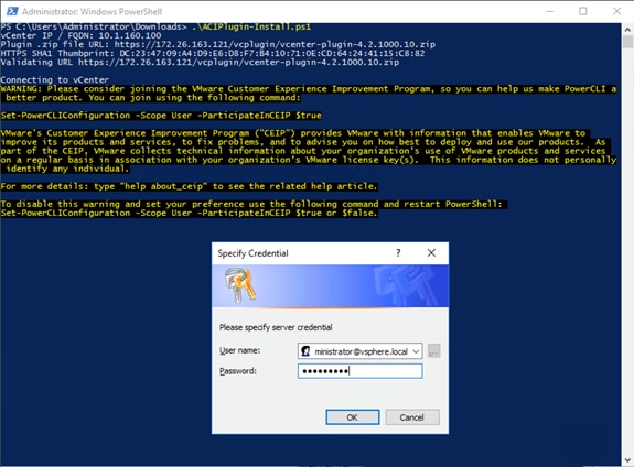
5. If the registration is successful, the following message should display.
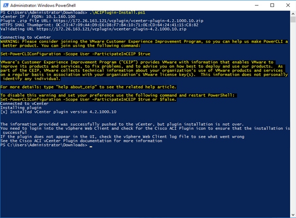
6. From the vSphere Web Client (Flex Client).
7. Select Home ->Administration -> Client Plug-Ins.
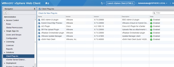
8. Wait for inprogress state to complete.
9. Click Check for New Plug-ins if the ACI Plugin does not appear in the Client Plug-Ins list.
10. Log out and log back into the vSphere Client if advised.
11. Within Home, the Cisco ACI Fabric icon should appear.
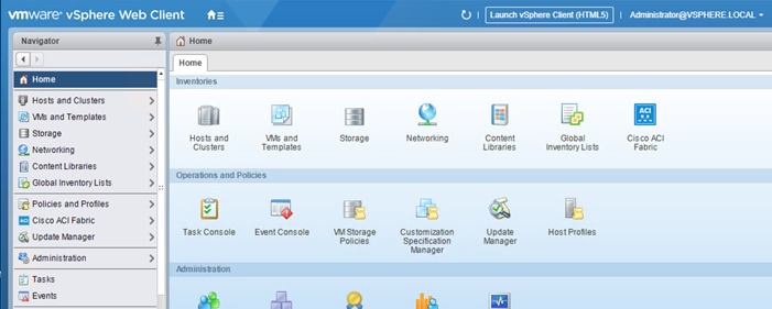
12. Click the Cisco ACI Fabric Icon
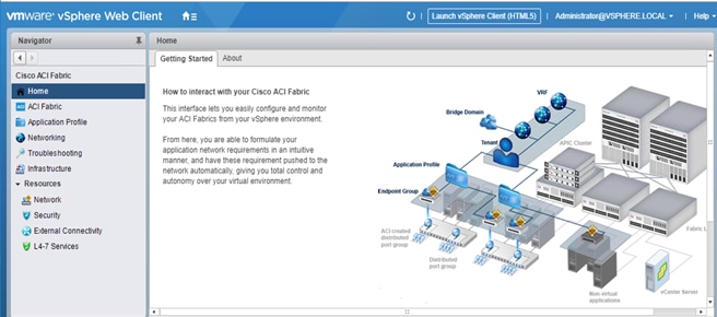
13. In the center pane, select Connect vSphere to your ACI Fabric.
14. Click Yes to add a new ACI Fabric.
15. Enter one APIC IP address or FQDN and uncheck Use Certificate.
16. Enter the admin Username and Password.
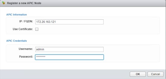
17. Click OK.
18. Click OK to confirm the addition of the other APICs.

Create Virtual Machine Manager (VMM) Domain in APIC
To configure the VMware vSphere VMM integration for managing a VMware vDS within vCenter perform the following steps:
1. In the APIC GUI, select Virtual Networking > Inventory.
2. On the left, expand VMM Domains > VMware.
3. Right-click VMware and select Create vCenter Domain.
4. Name the Virtual Switch VSV-vDS. Leave VMware vSphere Distributed Switch selected.
5. Select the VSV-UCS_Domain_AttEntityP Associated Attachable Entity Profile.
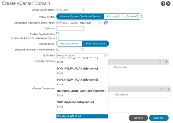
6. Under VLAN Pool, select Create VLAN Pool.
7. Name the VLAN Pool VSV-Application. Leave Dynamic Allocation selected.
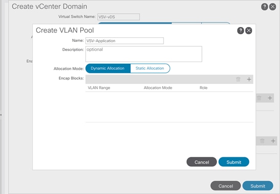
8. Click the “+” to add a block of VLANs to the pool.
9. Enter the VLAN range <1400-1499> and click OK.
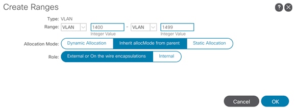
10. Click Submit to complete creating the VLAN Pool.
11. Click the “+” to the right of vCenter Credentials to add credentials for the vCenter.
12. For name, enter the vCenter hostname. Provide the appropriate username and password for the vCenter.
13. Click OK to complete creating the vCenter credentials.
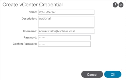
![]() The Administrator account is used in this example, but an APIC account can be created within the vCenter to enable the minimum set of privileges. For more information, see the ACI Virtualization Guide on cisco.com.
The Administrator account is used in this example, but an APIC account can be created within the vCenter to enable the minimum set of privileges. For more information, see the ACI Virtualization Guide on cisco.com.
14. Click the “+” to the right of vCenter to add the vCenter linkage.
15. Enter the vCenter hostname for Name. Enter the vCenter FQDN or IP address.
16. Leave vCenter Default for the DVS Version.
17. Enable Stats Collection.
18. For Datacenter, enter the exact Datacenter name specified in vCenter.
19. Do not select a Management EPG.
20. For Associated Credential, select the vCenter credentials entered in step 13.
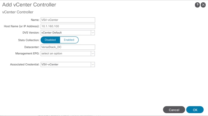
21. Click OK to complete the vCenter linkage.
22. For Port Channel Mode, select MAC Pinning-Physical-NIC-load.
23. For vSwitch Policy, select LLDP.
24. Leave NetFlow Exporter Policy unconfigured.
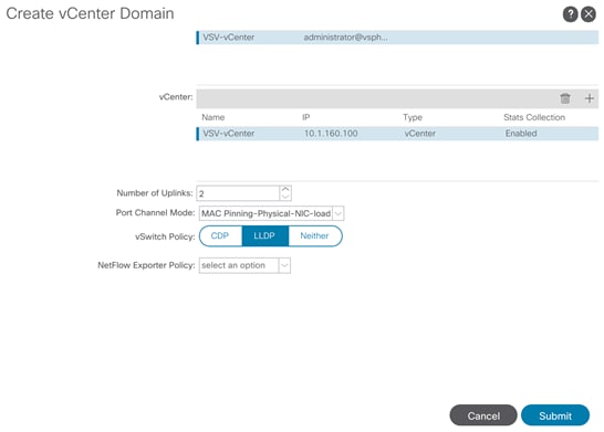
25. Click Submit to complete Creating the vCenter Domain.
![]() The vDS should now appear in vCenter.
The vDS should now appear in vCenter.
Add UCS Hosts to the vDS
To add the UCS hosts to the provisioned vDS, follow these steps:
1. Connect to the vSphere Web Client for the vCenter.
2. In the vSphere Web Client, navigate to the VSV-vDS distributed switch.
3. Right Click VSV-vDS.
4. On the Actions pane, select Add and Manage Hosts, and click Next.
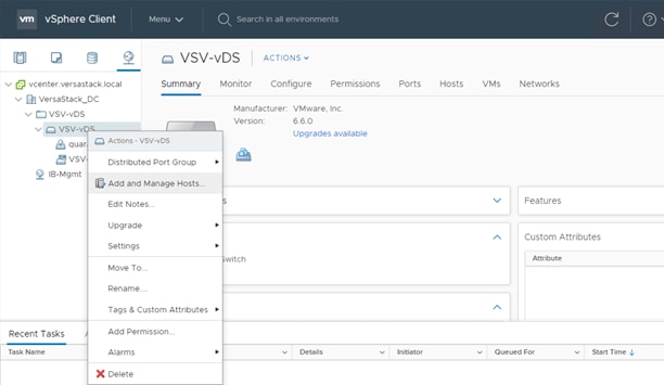
5. Leave Add hosts selected and click Next.
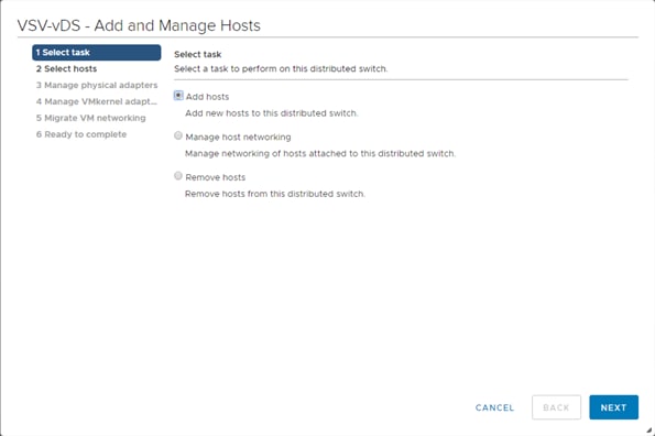
6. Click the + New hosts… option.
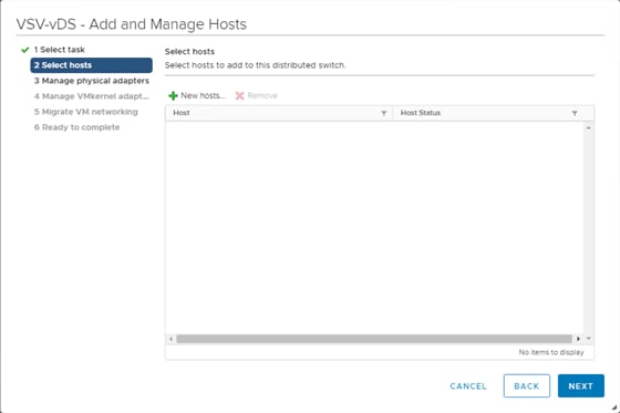
7. Select the installed hosts and click OK.
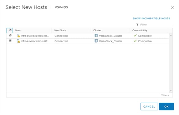
8. Click Next.
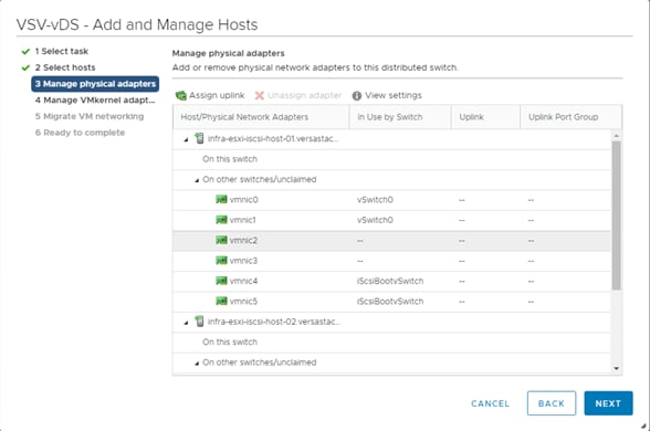
9. Select vmnic2 for the first host and click Assign uplink.
10. Check “Apply this uplink assignment to the rest of the hosts”.
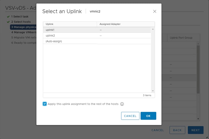
11. Leave uplink1 selected, check the “Apply this uplink assignment to the rest of the hosts” and click OK.
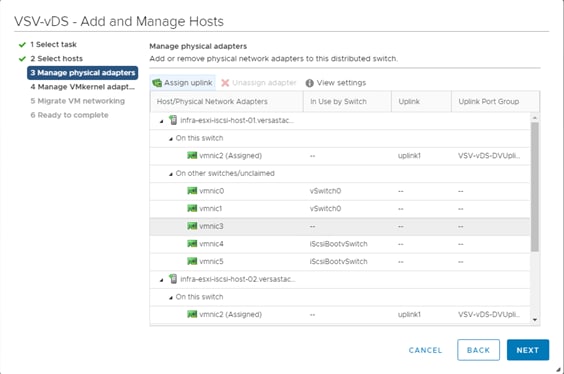
12. Select vmnic3 and click Assign uplink.
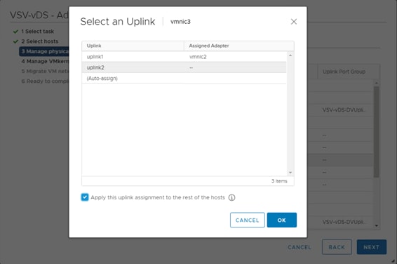
13. Leave uplink2 selected, check the “Apply this uplink assignment to the rest of the hosts”.
14. Click OK.
15. Click Next.
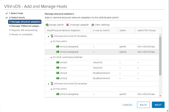
16. Click Next.
17. Click Next on the Manage VMkernel adapters screen.
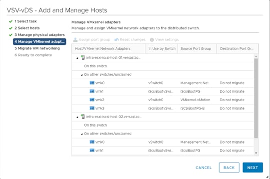
18. Click Next on the Manage VM Networking screen.
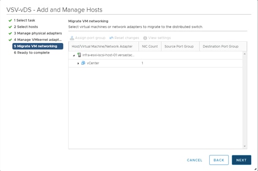
19. Review the Ready to complete page and click Finish to add the hosts.
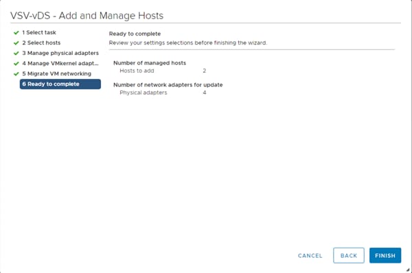
Cisco UCSM Integration
The ACI UCS Integration will automatically configure the dynamic VLANs allocated to port groups associated with the vDS VMM on both the UCS FI uplinks and vNIC Templates associated with the vDS vNICs.
To configure the ACI UCS Integration, follow these steps:
Install the ExternalSwitch app to the APIC
The Cisco External Switch Manager backend app provides connectivity between the APIC and the UCS FI as switches external to the ACI fabric. Installation of this app is required before the integration can communicate between these components.
1. Download the Cisco-ExternalSwitch-1.1.aci app from https://dcappcenter.cisco.com/externalswitch.html
2. Within the APIC GUI, select the Apps tab.
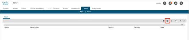
3. Click the Add Application icon.
4. Click Browse and select the downloaded .aci file for the ExternalSwitch App.
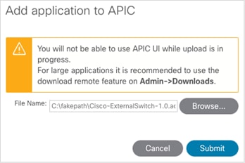
5. Click Submit.
6. Select the installed application.
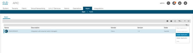
7. Right-click the options icon and click on Enable Application option.
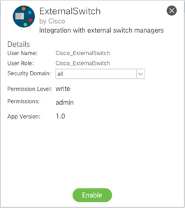
8. Click Enable.
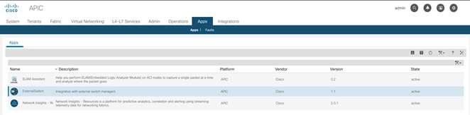
Create and configure an Integration Group
To configure the UCSM Integration within the APIC, follow these steps:
1. In the APIC GUI, select Integrations > Create Integration Group.
2. Provide the Integration Group with a name.
3. Click Submit.
4. Double-click the previously created Integration Group. [VSV-6454]
5. Right-click the UCSM folder and select the Create Integration Manager option.
6. Provide the following information to the pop-up window that appears:
a. Name – name to reference the UCSM
b. Device IP/FQDN – address of the UCSM
c. Username – login to use for the UCSM
d. Password – password to provide for the specified Username
e. Leave Deployment Policy and Preserve NIC Profile Config settings as defaults.
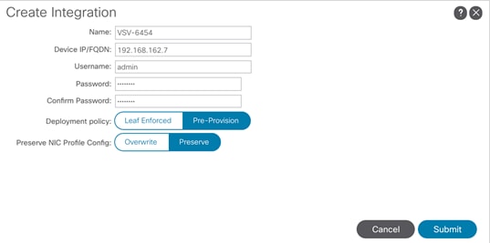
7. Click Submit.
Add the UCSM Integration as a VMM Switch Manager
To configure the UCSM Integration with the APIC to propagate the VLAN associations occurring within the VMM, follow these steps:
1. Connect to Virtual Networking -> Inventory within the APIC GUI.
2. Select VMM Domains -> VMware -> [VSV-vDS] -> Controllers -> VSV-vCenter within the left side Inventory.
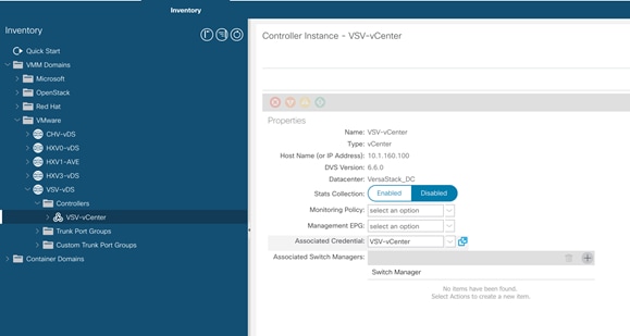
3. Click the + icon to the right side of the Associated Switch Managers bar.
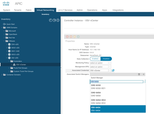
4. Select the configured UCSM Integration [VSV-6454].
5. Click Update.
Create an Application tenant with the Cisco ACI vCenter Plugin
With the vCenter Plugin in place, a tenant and application EPGs can be created directly from the vCenter. To begin, perform the following steps:
![]() The ACI VMware plugin is only supported with the vSphere Flash based Web Client. The following configuration procedure explains the creation of the application tenant using VMware plugin; the alternate procedure to configure the application tenant using Cisco APIC is explained in the next section of this document.
The ACI VMware plugin is only supported with the vSphere Flash based Web Client. The following configuration procedure explains the creation of the application tenant using VMware plugin; the alternate procedure to configure the application tenant using Cisco APIC is explained in the next section of this document.
1. Open up the vSphere Web Client connection to the vCenter with the Flex Client.
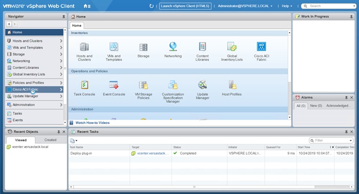
2. Open up the Cisco ACI Fabric icon.
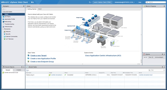
3. Click Create a new Tenant under Basic Tasks.
4. Provide a name for the Tenant and select the Fabric it will be created within.
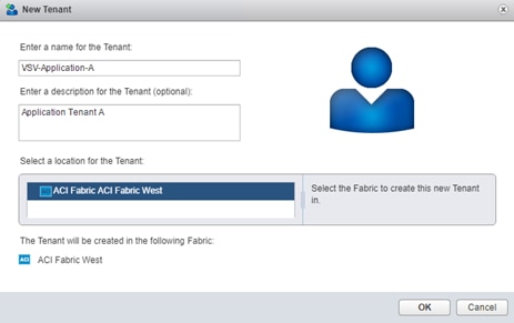
5. Click OK.
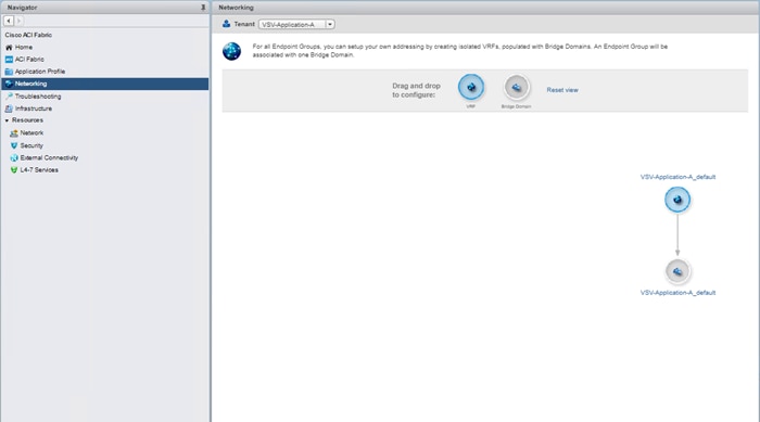
6. Click Networking within the Cisco ACI Fabric options of Navigator and select the newly created tenant from the Tenant drop-down list.
7. Confirm that the correct Tenant is selected, and right-click the Bridge Domain that was created with the VRF when the Tenant was formed, right-click and select the Edit settings option.
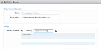
8. Enter a subnet gateway to use for the bridge domain, along with the CIDR / notation for the subnet mask to use. Click on the cloud icon to the right of the Gateway field to apply the subnet and the gateway.
![]() In this application example, the subnet is 172.20.100.0/22 and will be shared by all of the application EPGs that will have distinct connectivity rules applied to them via contracts despite existing within the same subnet. If dedicated subnets are preferred for each EPG, dedicated bridge domains should be defined here with the respective subnets to associate with the application EPGs.
In this application example, the subnet is 172.20.100.0/22 and will be shared by all of the application EPGs that will have distinct connectivity rules applied to them via contracts despite existing within the same subnet. If dedicated subnets are preferred for each EPG, dedicated bridge domains should be defined here with the respective subnets to associate with the application EPGs.
9. Click OK.
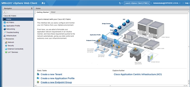
10. Go back to Home by clicking the Home Icon on left.
11. Click Create a new Endpoint Group under Basic Tasks.

12. Specify a Name for the Endpoint Group, select the Tenant [VSV-Application-A] and Application Profile [VSV-Application-A_default] to create the EPG in.
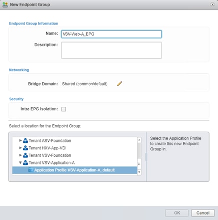
13. Click the pencil icon next to Bridge Domain.
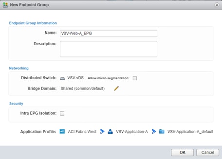
14. Expand the Tenant and VRF to select the Bridge Domain that was created for this tenant.
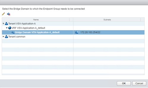
15. Click OK.
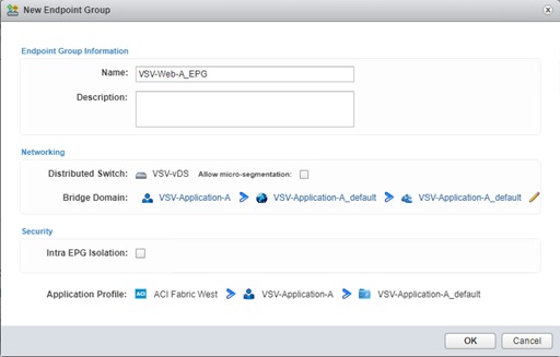
16. Click OK.
17. Repeat steps 10-16 to create additional EPGs [App and DB].
![]() The following will create a contract from the App EPG to connect to both the Web and DB EPGs without Web and DB being able to communicate with each other.
The following will create a contract from the App EPG to connect to both the Web and DB EPGs without Web and DB being able to communicate with each other.
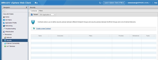
18. Click the Security option, confirm that the correct Tenant is selected, and click Create a new Contract.
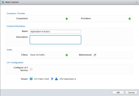
19. Provide a name for the Contract to allow traffic from the VSV-App-A EPG to the other two members. Click the green + icon to the right of Consumers.
20. Select the VSV-Web-A and VSV-DB-A EPGs from within the 3-Tier-App, and drag each over to the right side. Click OK.
21. Click the green + icon to the right of Providers.
22. Select the VSV-Application-A EPG from within the 3-Tier-App and drag it over to the right side. Click OK.
23. Click the green + icon next to Filters.
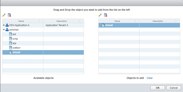
24. Expand the common tenant, select the default contract object and drag it to the right side. Click OK and Click OK again.
![]() The default filter will allow all traffic and may be too permissive for a production environment. Alternately, select the tenant and select the Create a new filter icon next to the pencil to create a set of granular port and protocol specific filters for appropriate traffic between the EPGs.
The default filter will allow all traffic and may be too permissive for a production environment. Alternately, select the tenant and select the Create a new filter icon next to the pencil to create a set of granular port and protocol specific filters for appropriate traffic between the EPGs.
25. Click OK to create the contract from VSV-App-A to the VSV-Web-A and VSV-DB-A EPGs.
Add External Connectivity to Appropriate EPGs
The Allow-Shared-L3-Out contract that was previously created can be associated to EPGs that will need to have access to appropriate external networks. For this contract to be applied, or to grant these EPGs access to contracts from other tenants, the Bridge Domain will need to be changed from the default setting of Private to VRF that is set when a Bridge Domain is created in the vCenter ACI Plugin.
To make this change, follow these steps:
1. Connect to the APIC GUI.
2. Select the Tenants tab and expand within the application tenant: Networking -> Bridge Domains -> <Bridge Domain used> -> Subnets.
3. Select the subnet created for the Bridge Domain.
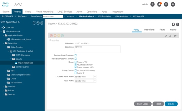
4. Unselect “Private to VRF”
5. Select the check boxes for “Advertised Externally” and “Shared between VRFs”.
6. Click Submit.
7. Click Submit Changes.
8. Change the Tenant to common within the Contracts tab of Security. Right-click the Allow-Shared-L3Out contract and select the Edit settings option.
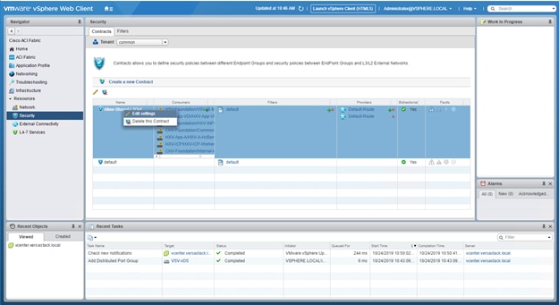
9. Click the first green + icon to list the Consumers.
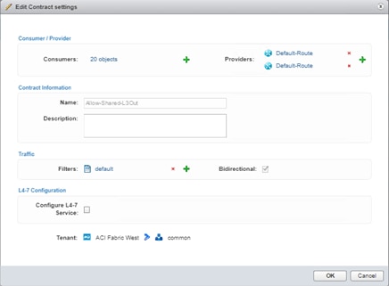
10. Expand the appropriate application tenant and contained application profile. Select any EPG that should be set up to have external connectivity and drag those EPGs over to the right. Click OK.
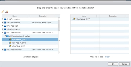
11. Click OK to make changes to the Allow-Shared-L3Out contract.
12. Log into the Nexus 7000 routers (172.20.101.0/24) which is being advertised. Nexus 7000 routers serve as gateways to outside networks, networks outside ACI, and includes both internal networks and Internet in this design.
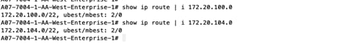
Create an Application tenant with the Cisco ACI APIC
This section details the steps for creating a sample two-tier application called Application-B using Cisco APIC GUI. This tenant will comprise of a Web and DB tier which will be mapped to relevant EPGs on the ACI fabric.
To deploy the Application Tenant and associate it to the VM networking, follow these steps:
Configure Tenant
1. In the APIC Advanced GUI, select Tenants.
2. At the top select Tenants > Add Tenant.
3. Name the Tenant VSV-Application-B.
4. For the VRF Name, also enter VSV-App-B_VRF. Leave the Take me to this tenant when I click finish checkbox checked.
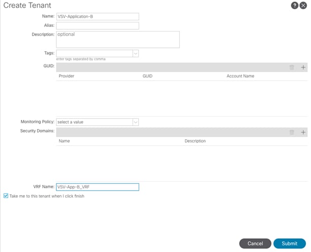
5. Click SUBMIT to finish creating the Tenant.
Configure Bridge Domains
To configure bridge domains, follow these steps:
1. In the left pane expand Tenant VSV-Application-B > Networking.
2. Right-click the Bridge Domain and select Create Bridge Domain.
![]() In this deployment, one bridge domain will be created to host Web and App application tiers. Customers can choose to create two Bridge Domains for each tier.
In this deployment, one bridge domain will be created to host Web and App application tiers. Customers can choose to create two Bridge Domains for each tier.
3. Name the Bridge Domain VSV-App-B_BD
4. Select VSV-VSV-App-B_VRF from the VRF drop-down list.
5. Select Custom under Forwarding and enable Flood for L2 Unknown Unicast.

6. Click Next.
7. Under L3 Configurations, make sure Limit IP Learning to Subnet is selected and select EP Move Detection Mode – GARP based detection.
8. Select the + option to the far right of Subnets.

9. Provide the appropriate Gateway IP and mask for the subnet.
10. Select the Scope options for Advertised Externally and Shared between VRFs.
11. Click OK.
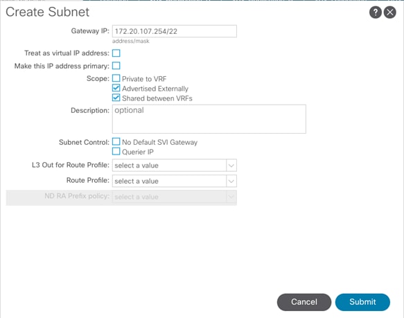
12. Click Submit.
Create Application Profile for Application-B
To create an application profile for Application-B, follow these steps:
1. In the left pane, expand tenant VSV-Application-B, right-click Application Profiles and select Create Application Profile.
2. Name the Application Profile VSV-App-B_AP and click Submit to complete adding the Application Profile.
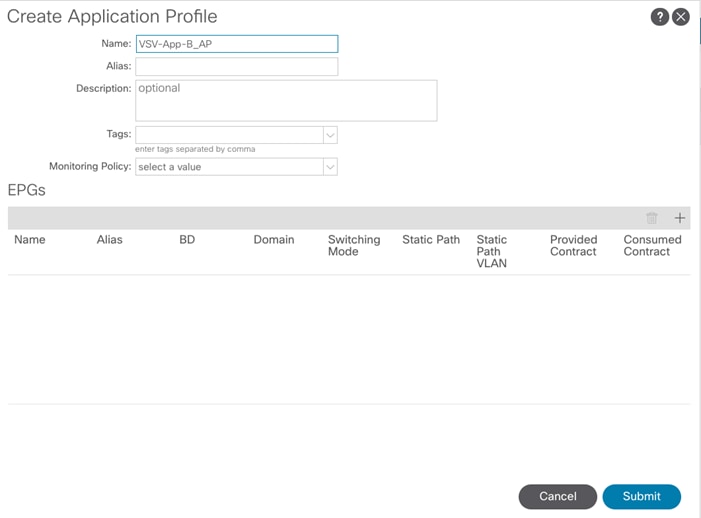
Create End Point Groups
To create the EPGs for Application-B, follow these steps:
EPG VSV-Web-B_EPG
1. In the left pane expand Application Profiles > VSV-Application-B.
2. Right-click Application EPGs and select Create Application EPG.
3. Name the EPG VSV-Web-B_EPG. Leave Intra EPG Isolation Unenforced.
4. From the Bridge Domain drop-down list, select VSV-App-B_BD.
5. Check the check box next to Associate to VM Domain Profiles.
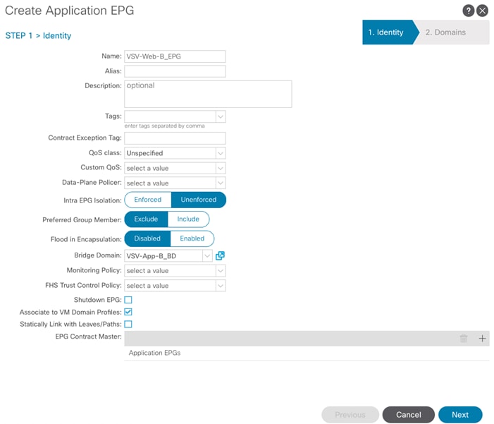
6. Click NEXT.
7. Click + to Associate VM Domain Profiles.
8. From the Domain Profile drop-down list, select VMware domain. If customers have deployed both VDS and AVS domains, both the domain will be visible in the drop-down list as shown below. In this example, VMware domain for VDS is selected to deploy the EPG.
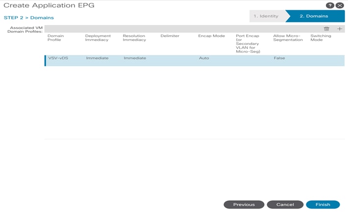
9. Change the Deployment Immediacy and Resolution Immediacy to Immediate.
10. Click UPDATE.
11. Click FINISH to complete creating the EPG.
EPG VSV-DB-B_EPG
1. In the left pane expand Application Profiles > VSV-Application-B.
2. Right-click Application EPGs and select Create Application EPG.
3. Name the EPG VSV-DB-B_EPG. Leave Intra EPG Isolation Unenforced.
4. From the Bridge Domain drop-down list, select VSV-App-B_BD.
5. Check the check box next to Associate to VM Domain Profiles.
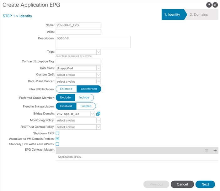
6. Click NEXT.
7. Click + to Associate VM Domain Profiles.
8. From the Domain Profile drop-down list, select VMware domain. If customers have deployed both VDS and AVS domains, both the domain will be visible in the drop-down list as shown below. In this example, VMware domain for VDS is selected to deploy the EPG.

9. Change the Deployment Immediacy and Resolution Immediacy to Immediate.
10. Click UPDATE.
11. Click FINISH to complete creating the EPG.
12. At this point, two new port-groups should have been created on the VMware VDS. Log into the vSphere Web Client browse to Networking > VDS and verify.
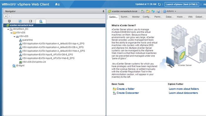
Configure Contracts
The following will create a contract from the App EPG to connect to DB EPG:
Web-Tier to DB-Tier Contract
1. In the APIC Advanced GUI, select Tenants > VSV-Application-B.
2. In the left pane, expand Tenant VSV-Application-B > Application Profiles > VSV-App-B_AP > Application EPGs > EPG VSV-Web-B_EPG.
3. Right-click on Contract and select Add Provided Contract.
4. In the Add Provided Contract window, from the Contract drop-down list, select Create Contract.
5. Name the Contract Allow-Web-to-DB.
6. Select Tenant for Scope.
7. Click + to add a Contract Subject.
8. Name the subject Allow-Web-to-DB.
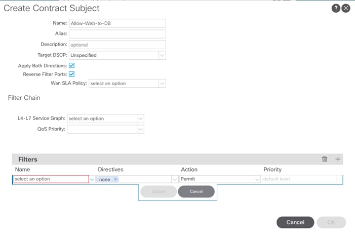
9. Click + under Filter Chain on the right side of the Filters bar to add a Filter.
10. From the drop-down Name list, Click + to create a new filter.
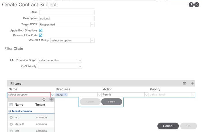
11. Click + under Filter Chain on the right side of the Filters bar to add a Filter.
12. From the drop-down Name list, click + to create a new filter.
13. Name the filer and set granular port and protocol specific filters for appropriate traffic between the EPGs. Alternately, select the default filter to allow all traffic between the EPGs.
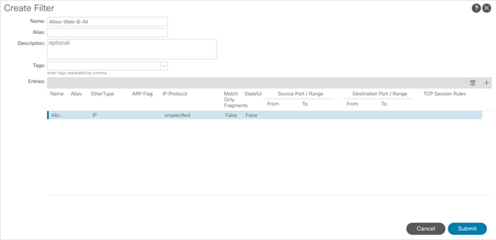
14. Click OK to add the Contract Subject.
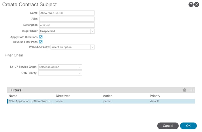
15. Click SUBMIT.
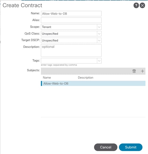
16. Click SUBMIT again.
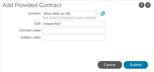
17. In the APIC Advanced GUI, select Tenants > VSV-Application-B.
18. In the left pane, expand Tenants > VSV-Application-B > Application Profiles > VSV-App-B_AP > Application EPGs > EPG VSV-DB-B_EPG.
19. Right-click Contract and select Add Consumed Contract.
20. In the Add Consumed Contract window, from the Contract drop-down list, select Allow-Web-to-DB.
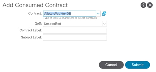
Web-Tier to Shared L3 Out Contract
To enable Application-B’s Web VMs to communicate outside the Fabric, Shared L3 Out contract defined in the Common Tenant will be consumed by the Web EPG. To enable Web VMs to outside the fabric, follow these steps:
1. In the left navigation pane, expand Tenants > VSV-Application-B > Application Profiles > VSV-App-B_AP > Application EPGs > EPG VSV-Web-B_EPG.
2. Right-click Contract and select Add Consumed Contract.
3. In the Add Consumed Contract window, from the Contract drop-down list, select Allow-Shared-L3Out.
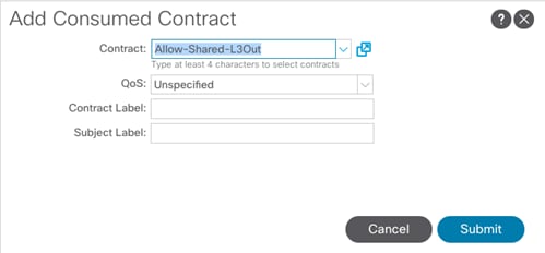
4. Click Submit to complete adding the Consumed Contract.
With the association of contracts to the Web and DB EPGs, the application environment now has access to outside (L3Out) networks and the DB tier is limited to accessing only the Web tier.
Products and Solutions
Cisco Unified Computing System:
http://www.cisco.com/en/US/products/ps10265/index.html
Cisco UCS 6400 Series Fabric Interconnects:
Cisco UCS 5100 Series Blade Server Chassis:
http://www.isco.com/en/US/products/ps10279/index.html
Cisco UCS B-Series Blade Servers:
Cisco UCS C-Series Rack Servers:
http://www.cisco.com/c/en/us/products/servers-unified-computing/ucs-c-series-rack-servers/index.html
Cisco UCS Adapters:
http://www.cisco.com/en/US/products/ps10277/prod_module_series_home.html
Cisco UCS Manager:
http://www.cisco.com/en/US/products/ps10281/index.html
Cisco Intersight:
https://www.cisco.com/c/en/us/products/servers-unified-computing/intersight/index.html
Cisco Nexus 9000 Series Switches:
Cisco Application Centric Infrastructure:
Cisco Data Center Network Manager:
Cisco UCS Director:
https://www.cisco.com/c/en/us/products/servers-unified-computing/ucs-director/index.html
VMware vCenter Server:
http://www.vmware.com/products/vcenter-server/overview.html
VMware vSphere:
https://www.vmware.com/products/vsphere
IBM FlashSystem 9100:
https://www.ibm.com/us-en/marketplace/flashsystem-9100
Interoperability Matrixes
Cisco UCS Hardware Compatibility Matrix:
https://ucshcltool.cloudapps.cisco.com/public/
VMware and Cisco Unified Computing System:
http://www.vmware.com/resources/compatibility
IBM System Storage Interoperation Center:
http://www-03.ibm.com/systems/support/storage/ssic/interoperability.wss
VersaStack Configuration Backups
Cisco UCS Backup
Automated backup of the Cisco UCS domain is important for recovery of the Cisco UCS Domain from issues ranging from catastrophic failure to human error. There is a native backup solution within Cisco UCS that allows local or remote backup using FTP/TFTP/SCP/SFTP as options and is detailed below.
Backups created can be a binary file containing the Full State, which can be used for a restore to the original or a replacement pair of fabric interconnects. Alternately this XML configuration file consisting of All configurations, just System configurations, or just Logical configurations of the Cisco UCS Domain. For scheduled backups, options will be Full State or All Configuration, backup of just the System or Logical configurations can be manually initiated.
To schedule the backup, follow these steps within the Cisco UCS Manager GUI:
1. Select Admin within the Navigation pane and select All.
2. Click the Policy Backup & Export tab within All.
3. For a Full State Backup, All Configuration Backup, or both, specify the following:
a. Hostname : <IP or FQDN of host that will receive the backup>
b. Protocol: [FTP/TFTP/SCP/SFTP]
c. User: <account on host to authenticate>
d. Password: <password for account on host>
e. Remote File: <full path and filename prefix for backup file>
f. Admin State: <select Enable to activate the schedule on save, Disable to disable schedule on save>
g. Schedule: [Daily/Weekly/Bi Weekly]
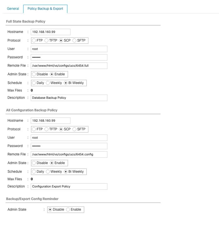
4. Click Save Changes to create the Policy.
Cisco ACI Backups
APIC configuration policies can be exported or backed. This can be done from any active and fully fit APIC within the ACI fabric. The backup and restore process does not require backup of individual components.
Backups are configurable through an export policy that allows either scheduled or immediate backups to a remote server (preferred) or, in the case where an external SCP/FTP server is not available, backups to be written to the local APIC file system.
Backup/export policies can be configured to be run on-demand or based on a recurring schedule. Cisco recommends that a current Backup be performed before making any major system configuration changes or applying software updates.
Adding a Remote Location (SCP) Using the GUI
To add a remote location, using the GUI, follow these steps:
1. On the menu bar, choose Admin > Import/Export.
2. In the Navigation pane, choose Remote Locations.
3. In the Work pane, choose Actions > Create Remote Location.
4. In the Create Remote Location dialog box, perform the following actions:
a. Enter a remote location name.
b. Enter a hostname/IP address.
c. Choose a protocol.
d. Enter a remote path.
e. Enter a remote port.
f. Enter a username.
g. Enter a password.
h. Choose a management EPG. The default is Out-of-Band.
5. Click Submit.
Creating a One-Time Export Policy Using the GUI
To create a one-time export policy, follow these steps: The procedure details a configuration export policy, but the procedure for a technical support export policy is similar.
1. On the menu bar, choose Admin > Import/Export.
2. In the Navigation pane, choose Export Policies > Configuration.
3. In the Work pane, choose Actions > Create Configuration Export Policy.
4. In the Create Configuration Export Policy dialog box, perform the following actions:
a. Name = Export_Policy_Name
b. Format = XML
c. Start Now = Yes
d. Export Destination = Choose_the_Remote_location_created_above
5. Click Submit.
Two optional configurations are applying a scheduler policy if you want to setup a recurring operation, and specifying a specific Distinguished Name (DN) if you want to backup only a subset of the Management Information Tree (MIT).
Verifying Exporting a Policy was Successful Using the GUI
To verify a successful exporting of a policy, follow these steps:
1. On the menu bar, choose Admin > Import/Export.
2. In the Navigation pane, choose Export Policies > Configuration > Export Name.
3. In the Work pane, choose the Operational tab.
a. The State should change from "pending" to "success" when the export completes correctly.
b. (Optional) Confirm on the SCP server that the backup filename exists.
For detailed information on ACI Backups, go to: https://www.cisco.com/c/en/us/td/docs/switches/datacenter/aci/apic/sw/1-x/Operating_ACI/guide/b_Cisco_Operating_ACI/b_Cisco_Operating_ACI_chapter_01.html#concept_6298EAB89B914E00A01498166957392B
VMware VCSA Backup
Basic backup of the vCenter Server Appliance is also available within the native capabilities of the VCSA, though within the default solution this is manually initiated for each backup operation. To create a backup, follow these steps:
1. Connect to the VCSA Console at https://<VCSA IP>:5480
2. Click Backup in the left side menu.
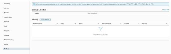
3. Click Configure to open up the Backup Appliance Dialogue.
4. Fill in all the fields based on your requirement.
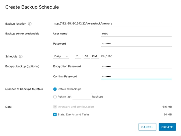
5. Review and click CREATE to create the backup schedule.
6. Restoration can be initiated with the backed-up files using the Restore function of the VCSA 6.7 Installer.
Sreenivasa Edula, Technical Marketing Engineer, UCS Data Center Solutions Engineering, Cisco Systems, Inc.
Sreeni is a Technical Marketing Engineer in the UCS Data Center Solutions Engineering team focusing on converged and hyper-converged infrastructure solutions, prior to that he worked as a Solutions Architect at EMC Corporation. He has experience in Information Systems with expertise across Cisco Data Center technology portfolio, including DC architecture design, virtualization, compute, network, storage and cloud computing.
Warren Hawkins, Virtualization Test Specialist for IBM Spectrum Virtualize, IBM
Working as part of the development organization within IBM Storage, Warren Hawkins is also a speaker and published author detailing best practices for integrating IBM Storage offerings into virtualized infrastructures. Warren has a background in supporting Windows and VMware environments working in second-line and third-line support in both public and private sector organizations. Since joining IBM in 2013, Warren has played a crucial part in customer engagements and, using his field experience, has established himself as the Test Lead for the IBM Spectrum Virtualize™ product family, focusing on clustered host environments