Cisco HyperFlex 4.0 with Citrix Virtual Apps and Desktops and VMware ESXi for up to 5000 Users
Available Languages
Bias-Free Language
The documentation set for this product strives to use bias-free language. For the purposes of this documentation set, bias-free is defined as language that does not imply discrimination based on age, disability, gender, racial identity, ethnic identity, sexual orientation, socioeconomic status, and intersectionality. Exceptions may be present in the documentation due to language that is hardcoded in the user interfaces of the product software, language used based on RFP documentation, or language that is used by a referenced third-party product. Learn more about how Cisco is using Inclusive Language.
- US/Canada 800-553-2447
- Worldwide Support Phone Numbers
- All Tools
 Feedback
 Feedback

Cisco HyperFlex 4.0 with Citrix Virtual Apps and Desktops and VMware ESXi for up to 5000 Users
Deployment Guide for Cisco HyperFlex with Virtual Desktop Infrastructure for Citrix Virtual Apps and Desktops using Cisco HyperFlex Data Platform v4.0.2a and VMware ESXi 6.7
Published: July 2020

About the Cisco Validated Design Program
The Cisco Validated Design (CVD) program consists of systems and solutions designed, tested, and documented to facilitate faster, more reliable, and more predictable customer deployments. For more information, go to:
http://www.cisco.com/go/designzone.
ALL DESIGNS, SPECIFICATIONS, STATEMENTS, INFORMATION, AND RECOMMENDATIONS (COLLECTIVELY, "DESIGNS") IN THIS MANUAL ARE PRESENTED "AS IS," WITH ALL FAULTS. CISCO AND ITS SUPPLIERS DISCLAIM ALL WARRANTIES, INCLUDING, WITHOUT LIMITATION, THE WARRANTY OF MERCHANTABILITY, FITNESS FOR A PARTICULAR PURPOSE AND NONINFRINGEMENT OR ARISING FROM A COURSE OF DEALING, USAGE, OR TRADE PRACTICE. IN NO EVENT SHALL CISCO OR ITS SUPPLIERS BE LIABLE FOR ANY INDIRECT, SPECIAL, CONSEQUENTIAL, OR INCIDENTAL DAMAGES, INCLUDING, WITHOUT LIMITATION, LOST PROFITS OR LOSS OR DAMAGE TO DATA ARISING OUT OF THE USE OR INABILITY TO USE THE DESIGNS, EVEN IF CISCO OR ITS SUPPLIERS HAVE BEEN ADVISED OF THE POSSIBILITY OF SUCH DAMAGES.
THE DESIGNS ARE SUBJECT TO CHANGE WITHOUT NOTICE. USERS ARE SOLELY RESPONSIBLE FOR THEIR APPLICATION OF THE DESIGNS. THE DESIGNS DO NOT CONSTITUTE THE TECHNICAL OR OTHER PROFESSIONAL ADVICE OF CISCO, ITS SUPPLIERS OR PARTNERS. USERS SHOULD CONSULT THEIR OWN TECHNICAL ADVISORS BEFORE IMPLEMENTING THE DESIGNS. RESULTS MAY VARY DEPENDING ON FACTORS NOT TESTED BY CISCO.
CCDE, CCENT, Cisco Eos, Cisco Lumin, Cisco Nexus, Cisco StadiumVision, Cisco TelePresence, Cisco WebEx, the Cisco logo, DCE, and Welcome to the Human Network are trademarks; Changing the Way We Work, Live, Play, and Learn and Cisco Store are service marks; and Access Registrar, Aironet, AsyncOS, Bringing the Meeting To You, Catalyst, CCDA, CCDP, CCIE, CCIP, CCNA, CCNP, CCSP, CCVP, Cisco, the Cisco Certified Internetwork Expert logo, Cisco IOS, Cisco Press, Cisco Systems, Cisco Systems Capital, the Cisco Systems logo, Cisco Unified Computing System (Cisco UCS), Cisco UCS B-Series Blade Servers, Cisco UCS C-Series Rack Servers, Cisco UCS S-Series Storage Servers, Cisco UCS Manager, Cisco UCS Management Software, Cisco Unified Fabric, Cisco Application Centric Infrastructure, Cisco Nexus 9000 Series, Cisco Nexus 7000 Series. Cisco Prime Data Center Network Manager, Cisco NX-OS Software, Cisco MDS Series, Cisco Unity, Collaboration Without Limitation, EtherFast, EtherSwitch, Event Center, Fast Step, Follow Me Browsing, FormShare, GigaDrive, HomeLink, Internet Quotient, IOS, iPhone, iQuick Study, LightStream, Linksys, MediaTone, MeetingPlace, MeetingPlace Chime Sound, MGX, Networkers, Networking Academy, Network Registrar, PCNow, PIX, PowerPanels, ProConnect, ScriptShare, SenderBase, SMARTnet, Spectrum Expert, StackWise, The Fastest Way to Increase Your Internet Quotient, TransPath, WebEx, and the WebEx logo are registered trademarks of Cisco Systems, Inc. and/or its affiliates in the United States and certain other countries.
All other trademarks mentioned in this document or website are the property of their respective owners. The use of the word partner does not imply a partnership relationship between Cisco and any other company. (0809R)
© 2020 Cisco Systems, Inc. All rights reserved.
Table of Contents
Cisco Unified Computing System
Cisco UCS 6454 Fabric Interconnect
Cisco HyperFlex HX-Series Nodes
Cisco HyperFlex HXAF220c-M5SX All-Flash Node
Cisco VIC 1457 MLOM Interface Cards
Cisco HyperFlex Compute-Only Nodes
Cisco HyperFlex Data Platform Software
Cisco HyperFlex Connect HTML5 Management Web Page
Cisco Intersight Cloud Based Management
Cisco HyperFlex HX Data Platform Administration Plug-in
Cisco HyperFlex HX Data Platform Controller
Data Operations and Distribution
Cisco UCS B-Series Blade Servers
Cisco UCS C-Series Rack-Mount Servers
Cisco UCS Service Profile Templates
Storage Platform Controller Virtual Machines
Cisco UCS Fabric Interconnect A
Cisco UCS Fabric Interconnect B
HyperFlex Installer VM Deployment
Cisco HyperFlex Cluster Configuration
Cisco HyperFlex Cluster Expansion
Auto-Support and Notifications
Cisco UCS vMedia and Boot Policies
Undo vMedia and Boot Policy Changes
Expansion with Compute-Only Nodes
Cisco Intersight Cloud-Based Management
Cisco Intersight HyperFlex Management
Build the Virtual Machines and Environment for Workload Testing
Software Infrastructure Configuration
Install and Configure Citrix Desktop Delivery Controller, Citrix Licensing, and StoreFront
Install Citrix Desktop Broker/Studio
Configure the Citrix VDI Site Administrators
Configure Additional Desktop Controller
Add the Second Delivery Controller to the Citrix Desktop Site
Install and Configure StoreFront
Additional StoreFront Configuration
Install the Citrix Provisioning Services Target Device Software
Create Citrix Provisioning Services vDisks
Install Citrix Virtual Apps and Desktop Virtual Desktop Agents
Provision Virtual Desktop Machines Using Citrix Provisioning Server
Provision Desktop Machines from Citrix Provisioning Services Console
Deploy Virtual Machines using Citrix Machine Creation Services for Persistent Desktops
Citrix Virtual Desktops Policies and Profile Management
Configure Citrix Virtual Desktops Policies
Configure User Profile Management
Test Methodology and Success Criteria
Recommended Maximum Workload and Configuration Guidelines
To keep pace with the market, you need systems that support rapid, agile development processes. Cisco HyperFlex™ Systems let you unlock the full potential of hyper-convergence and adapt IT to the needs of your workloads. The systems use an end-to-end software-defined infrastructure approach, combining software-defined computing in the form of Cisco HyperFlex HX-Series Nodes, software-defined storage with the powerful Cisco HyperFlex HX Data Platform, and software-defined networking with the Cisco UCS fabric that integrates smoothly with Cisco® Application Centric Infrastructure (Cisco ACI™).
Together with a single point of connectivity and management, these technologies deliver a pre-integrated and adaptable cluster with a unified pool of resources that you can quickly deploy, adapt, scale, and manage to efficiently power your applications and your business
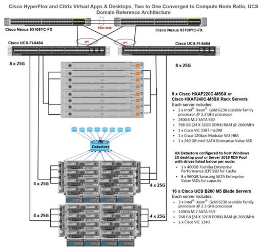
This document provides an architectural reference and design guide for up to 5000 RDS and 4000 VDI session workload on a 24-node (8x Cisco HyperFlex HXAF220C-M5SX server and 16x Cisco B200 M5 Compute only nodes) Cisco HyperFlex system. We provide deployment guidance and performance data for Citrix Virtual Desktops 1912 LTSR virtual desktops running Microsoft Windows 10 with Office 2016 and Windows Server 2019 for HSD. The solution is a pre-integrated, best-practice data center architecture built on the Cisco Unified Computing System (Cisco UCS), the Cisco Nexus® 9000 family of switches and Cisco HyperFlex Data Platform software version 4.0.2a.
The solution payload is 100 percent virtualized on Cisco HyperFlex HXAF220C-M5SX hyperconverged nodes and Cisco UCS B200 M5 Compute-Only Nodes booting through on-board M.2 SATA SSD drive running VMware ESXi hypervisor and the Cisco HyperFlex Data Platform storage controller virtual machine. The virtual desktops are configured with Virtual Desktops 1912 LTSR, which incorporates both traditional persistent and non-persistent virtual Windows 10 desktops, hosted applications and remote desktop service (RDS) Microsoft Server 2019 based desktops. The solution provides unparalleled scale and management simplicity. Citrix Virtual Desktops Provisioning Services or Machine Creation Services Windows 10 desktops, full clone desktops or Virtual Apps server-based desktops can be provisioned on an eight node Cisco HyperFlex cluster. Where applicable, this document provides best practice recommendations and sizing guidelines for customer deployment of this solution.
Introduction
The current industry trend in data center design is towards small, granularly expandable hyperconverged infrastructures. By using virtualization along with pre-validated IT platforms, customers of all sizes have embarked on the journey to “just-in-time capacity” using this new technology. The Cisco HyperFlex hyperconverged solution can be quickly deployed, thereby increasing agility and reducing costs. Cisco HyperFlex uses best of breed storage, server and network components to serve as the foundation for desktop virtualization workloads, enabling efficient architectural designs that can be quickly and confidently deployed and scaled-out.
Audience
The intended audience for this document includes, but is not limited to, sales engineers, field consultants, professional services, IT managers, partner engineering, and customers deploying the Cisco HyperFlex System. External references are provided wherever applicable, but readers are expected to be familiar with VMware, Citrix and Microsoft specific technologies, infrastructure concepts, networking connectivity, and security policies of the customer installation.
Purpose of this Document
This document provides a step-by-step design, configuration, and implementation guide for the Cisco Validated Design for a Cisco HyperFlex All-Flash system running four different Citrix Virtual Desktops/Virtual Apps workloads with Cisco UCS 6400 series Fabric Interconnects and Cisco Nexus 9000 series switches.
Documentation Roadmap
For the comprehensive documentation suite, refer to the Cisco UCS HX-Series Documentation Roadmap: https://www.cisco.com/c/en/us/td/docs/hyperconverged_systems/HyperFlex_HX_DataPlatformSoftware/HX_Documentation_Roadmap/HX_Series_Doc_Roadmap.html
![]() Note: A login is required for the Documentation Roadmap.
Note: A login is required for the Documentation Roadmap.
The Hyperconverged Infrastructure link: http://hyperflex.io
Solution Summary
The Cisco HyperFlex system provides a fully contained virtual server platform, with compute and memory resources, integrated networking connectivity, a distributed high-performance log-based filesystem for VM storage, and the hypervisor software for running the virtualized servers, all within a single Cisco UCS management domain.
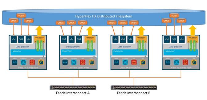
The following are the components of a Cisco HyperFlex system using the VMware ESXi Hypervisor:
· One pair of Cisco UCS Fabric Interconnects, choose from models:
- Cisco UCS 6454 Fabric Interconnect
· Eight Cisco HyperFlex HX-Series Rack-Mount Servers, choose from models:
- Cisco HyperFlex HXAF220c-M5SX All-Flash Rack-Mount Servers
· Sixteen Cisco UCS B200 M5 Servers for Compute-Only nodes
· Cisco HyperFlex Data Platform Software
· VMware vSphere ESXi Hypervisor
· VMware vCenter Server (end-user supplied)
· Citrix Virtual Apps & Desktops 1912 LTSR
Cisco Unified Computing System
Cisco Unified Computing System (Cisco UCS) is a next-generation data center platform that unites compute, network, and storage access. The platform, optimized for virtual environments, is designed using open industry-standard technologies and aims to reduce total cost of ownership (TCO) and increase business agility. The system integrates a low-latency, lossless 10 Gigabit Ethernet, 25 Gigabit Ethernet or 40 Gigabit Ethernet unified network fabric with enterprise-class, x86-architecture servers. It is an integrated, scalable, multi chassis platform in which all resources participate in a unified management domain.
The main components of Cisco Unified Computing System are:
· Computing: The system is based on an entirely new class of computing system that incorporates rack-mount and blade servers based on Intel Xeon Processors.
· Network: The system is integrated onto a low-latency, lossless, 10-Gbps, 25-Gbps or 40-Gbps unified network fabric, with an option for 100-Gbps uplinks. This network foundation consolidates LANs, SANs, and high-performance computing networks which are often separate networks today. The unified fabric lowers costs by reducing the number of network adapters, switches, and cables, and by decreasing the power and cooling requirements.
· Virtualization: The system unleashes the full potential of virtualization by enhancing the scalability, performance, and operational control of virtual environments. Cisco security, policy enforcement, and diagnostic features are now extended into virtualized environments to better support changing business and IT requirements.
· Storage access: The system provides consolidated access to both SAN storage and Network Attached Storage (NAS) over the unified fabric. By unifying storage access, the Cisco Unified Computing System can access storage over Ethernet, Fibre Channel, Fibre Channel over Ethernet (FCoE), and iSCSI. This provides customers with their choice of storage protocol and physical architecture, and enhanced investment protection. In addition, the server administrators can pre-assign storage-access policies for system connectivity to storage resources, simplifying storage connectivity, and management for increased productivity.
· Management: The system uniquely integrates all system components which enable the entire solution to be managed as a single entity by the Cisco UCS Manager (UCSM). The Cisco UCS Manager has an intuitive graphical user interface (GUI), a command-line interface (CLI), and a robust application programming interface (API) to manage all system configuration and operations. Cisco UCS can also be managed by Cisco Intersight, a cloud-based management and monitoring platform which offers a single pane of glass portal for multiple Cisco UCS systems across multiple locations.
The Cisco Unified Computing System is designed to deliver:
· A reduced Total Cost of Ownership and increased business agility.
· Increased IT staff productivity through just-in-time provisioning and mobility support.
· A cohesive, integrated system which unifies the technology in the data center. The system is managed, serviced and tested as a whole.
· Scalability through a design for hundreds of discrete servers and thousands of virtual machines and the capability to scale I/O bandwidth to match demand.
· Industry standards supported by a partner ecosystem of industry leaders.
Cisco UCS Fabric Interconnect
The Cisco UCS Fabric Interconnect (FI) is a core part of the Cisco Unified Computing System, providing both network connectivity and management capabilities for the system. Depending on the model chosen, the Cisco UCS Fabric Interconnect offers line-rate, low-latency, lossless Ethernet, Fibre Channel over Ethernet (FCoE) and Fibre Channel connectivity. Cisco UCS Fabric Interconnects provide the management and communication backbone for the Cisco UCS C-Series, Cisco UCS S-Series and HX-Series Rack-Mount Servers, Cisco UCS B-Series Blade Servers and Cisco UCS 5100 Series Blade Server Chassis. All servers and chassis, and therefore all blades, attached to the Cisco UCS Fabric Interconnects become part of a single, highly available management domain. In addition, by supporting unified fabrics, the Cisco UCS Fabric Interconnects provide both the LAN and SAN connectivity for all servers within its domain. The product family supports Cisco low-latency, lossless Ethernet unified network fabric capabilities, which increase the reliability, efficiency, and scalability of Ethernet networks. The Fabric Interconnect supports multiple traffic classes over the Ethernet fabric from the servers to the uplinks. Significant TCO savings come from an FCoE-optimized server design in which network interface cards (NICs), host bus adapters (HBAs), cables, and switches can be consolidated.
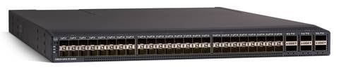
Cisco UCS 6454 Fabric Interconnect
The Cisco UCS 6454 54-Port Fabric Interconnect is a One-Rack-Unit (1RU) 10/25/40/100 Gigabit Ethernet, FCoE and Fibre Channel switch offering up to 3.82 Tbps throughput and up to 54 ports. The switch has 28 10/25-Gbps Ethernet ports, 4 1/10/25-Gbps Ethernet ports, 6 40/100-Gbps Ethernet uplink ports and 16 unified ports that can support 10/25-Gbps Ethernet ports or 8/16/32-Gbps Fibre Channel ports. All Ethernet ports are capable of supporting FCoE. Cisco HyperFlex nodes can connect at 10-Gbps or 25-Gbps speeds depending on the model of Cisco VIC card in the nodes and the SFP optics or cables chosen.
Cisco HyperFlex HX-Series Nodes
A standard HyperFlex cluster requires a minimum of three HX-Series “converged” nodes (i.e. nodes with shared disk storage). Data is replicated across at least two of these nodes, and a third node is required for continuous operation in the event of a single-node failure. Each node that has disk storage is equipped with at least one high-performance SSD drive for data caching and rapid acknowledgment of write requests. Each node also is equipped with additional disks, up to the platform’s physical limit, for long term storage and capacity.

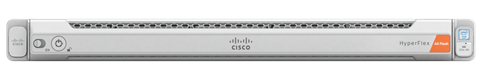
Cisco HyperFlex HXAF220c-M5SX All-Flash Node
This small footprint Cisco HyperFlex all-flash model contains a 240 GB M.2 form factor solid-state disk (SSD) that acts as the boot drive, a 240 GB housekeeping SSD drive, either a single 375 GB Optane NVMe SSD, a 1.6 TB NVMe SSD or 1.6 TB SAS SSD write-log drive, and six to eight 960 GB or 3.8 TB SATA SSD drives for storage capacity. For configurations requiring self-encrypting drives, the caching SSD is replaced with an 800 GB SAS SED SSD, and the capacity disks are also replaced with 960 GB or 3.8 TB SED SSDs.
![]() Note: In HX-series all-flash nodes either a 375 GB Optane NVMe SSD, a 1.6 TB SAS SSD or 1.6 TB NVMe SSD caching drive may be chosen. While the Optane and NVMe options can provide a higher level of performance, the partitioning of the three disk options is the same, therefore the amount of cache available on the system is the same regardless of the model chosen. Caching amounts are not factored in as part of the overall cluster capacity, only the capacity disks contribute to total cluster capacity.
Note: In HX-series all-flash nodes either a 375 GB Optane NVMe SSD, a 1.6 TB SAS SSD or 1.6 TB NVMe SSD caching drive may be chosen. While the Optane and NVMe options can provide a higher level of performance, the partitioning of the three disk options is the same, therefore the amount of cache available on the system is the same regardless of the model chosen. Caching amounts are not factored in as part of the overall cluster capacity, only the capacity disks contribute to total cluster capacity.
Cisco VIC 1457 MLOM Interface Cards
The Cisco UCS VIC 1387 Card is a dual-port Enhanced Quad Small Form-Factor Pluggable (QSFP+) 40-Gbps Ethernet and Fibre Channel over Ethernet (FCoE)-capable PCI Express (PCIe) modular LAN-on-motherboard (mLOM) adapter installed in the Cisco UCS HX-Series Rack Servers. The VIC 1387 is used in conjunction with the Cisco UCS 6332 or 6332-16UP model Fabric Interconnects.
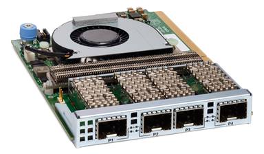
The Cisco UCS VIC 1457 is a quad-port Small Form-Factor Pluggable (SFP28) mLOM card designed for the M5 generation of Cisco UCS C-Series Rack Servers. The card supports 10-Gbps or 25-Gbps Ethernet and FCoE, where the speed of the link is determined by the model of SFP optics or cables used. The card can be configured to use a pair of single links, or optionally to use all four links as a pair of bonded links. The VIC 1457 is used in conjunction with the Cisco UCS 6454 model Fabric Interconnect.
The mLOM is used to install a Cisco VIC without consuming a PCIe slot, which provides greater I/O expandability. It incorporates next-generation converged network adapter (CNA) technology from Cisco, providing investment protection for future feature releases. The card enables a policy-based, stateless, agile server infrastructure that can present up to 256 PCIe standards-compliant interfaces to the host, each dynamically configured as either a network interface card (NICs) or host bus adapter (HBA). The personality of the interfaces is set programmatically using the service profile associated with the server. The number, type (NIC or HBA), identity (MAC address and World Wide Name [WWN]), failover policy, adapter settings, bandwidth, and quality-of-service (QoS) policies of the PCIe interfaces are all specified using the service profile.
Cisco HyperFlex Compute-Only Nodes
All current model Cisco UCS M4 and M5 generation servers, except the Cisco UCS C880 M4 and Cisco UCS C880 M5, may be used as compute-only nodes connected to a Cisco HyperFlex cluster, along with a limited number of previous M3 generation servers. All valid CPU and memory configurations are allowed in the compute-only nodes, and the servers can be configured to boot from SAN, local disks, or internal SD cards. The following servers may be used as compute-only nodes:
· Cisco UCS B200 M3 Blade Server
· Cisco UCS B200 M4 Blade Server
· Cisco UCS B200 M5 Blade Server
· Cisco UCS B260 M4 Blade Server
· Cisco UCS B420 M4 Blade Server
· Cisco UCS B460 M4 Blade Server
· Cisco UCS B480 M5 Blade Server
· Cisco UCS C220 M3 Rack-Mount Servers
· Cisco UCS C220 M4 Rack-Mount Servers
· Cisco UCS C220 M5 Rack-Mount Servers
· Cisco UCS C240 M3 Rack-Mount Servers
· Cisco UCS C240 M4 Rack-Mount Servers
· Cisco UCS C240 M5 Rack-Mount Servers
· Cisco UCS C460 M4 Rack-Mount Servers
· Cisco UCS C480 M5 Rack-Mount Servers
· Cisco UCS C480 ML Rack-Mount Servers
Cisco HyperFlex Data Platform Software
The Cisco HyperFlex HX Data Platform is a purpose-built, high-performance, distributed file system with a wide array of enterprise-class data management services. The data platform’s innovations redefine distributed storage technology, exceeding the boundaries of first-generation hyperconverged infrastructures. The data platform has all the features expected in an enterprise shared storage system, eliminating the need to configure and maintain complex Fibre Channel storage networks and devices. The platform simplifies operations and helps ensure data availability. Enterprise-class storage features include the following:
· Data protection creates multiple copies of the data across the cluster so that data availability is not affected if single or multiple components fail (depending on the replication factor configured).
· Stretched clusters allow nodes to be evenly split between two physical locations, keeping a duplicate copy of all data in both locations, thereby providing protection in case of an entire site failure.
· Logical availability zones provide multiple logical grouping of nodes and distributes the data across these groups in such a way that no single group has more than one copy of the data. This enables enhanced protection from node failures, allowing for more nodes to fail while the overall cluster remains online.
· Deduplication is always on, helping reduce storage requirements in virtualization clusters in which multiple operating system instances in guest virtual machines result in large amounts of replicated data.
· Compression further reduces storage requirements, reducing costs, and the log-structured file system is designed to store variable-sized blocks, reducing internal fragmentation.
· Replication copies virtual machine level snapshots from one Cisco HyperFlex cluster to another, to facilitate recovery from a cluster or site failure, via a failover to the secondary site of all VMs.
· Encryption stores all data on the caching and capacity disks in an encrypted format, to prevent accidental data loss or data theft. Key management can be done using local Cisco UCS Manager managed keys, or third-party Key Management Systems (KMS) via the Key Management Interoperability Protocol (KMIP).
· Thin provisioning allows large volumes to be created without requiring storage to support them until the need arises, simplifying data volume growth and making storage a “pay as you grow” proposition.
· Fast, space-efficient clones rapidly duplicate virtual storage volumes so that virtual machines can be cloned simply through metadata operations, with actual data copied only for write operations.
· Snapshots help facilitate backup and remote-replication operations, which are needed in enterprises that require always-on data availability.
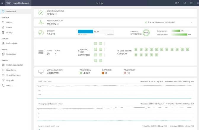
Cisco HyperFlex Connect HTML5 Management Web Page
An HTML 5 based Web UI named HyperFlex Connect is available for use as the primary management tool for Cisco HyperFlex. Through this centralized point of control for the cluster, administrators can create volumes, monitor the data platform health, and manage resource use. Administrators can also use this data to predict when the cluster will need to be scaled. To use the HyperFlex Connect UI, connect using a web browser to the HyperFlex cluster IP address: http://<hx controller cluster ip>.
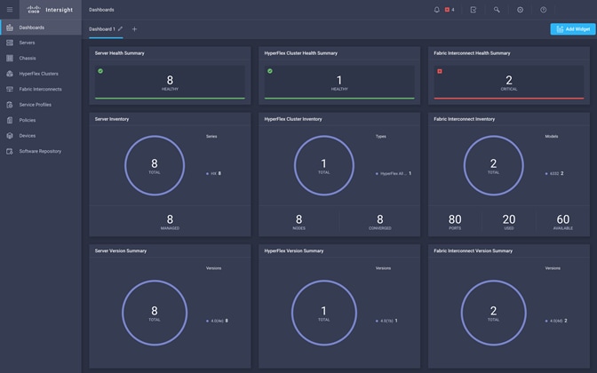
Cisco Intersight Cloud Based Management
Cisco Intersight (https://intersight.com) is the latest visionary cloud-based management tool, designed to provide a centralized off-site management, monitoring and reporting tool for all of your Cisco UCS based solutions, and can be used to deploy and manage Cisco HyperFlex clusters. Cisco Intersight offers direct links to Cisco UCS Manager and Cisco HyperFlex Connect for systems it is managing and monitoring. The Cisco Intersight website and framework is being constantly upgraded and extended with new and enhanced features independently of the products that are managed, meaning that many new features and capabilities can come with no downtime or upgrades required by the end users. This unique combination of embedded and online technologies results in a complete cloud-based management solution that can care for Cisco HyperFlex throughout the entire lifecycle, from deployment through retirement.
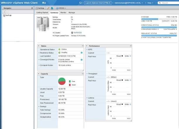
Cisco HyperFlex HX Data Platform Administration Plug-in
The Cisco HyperFlex HX Data Platform is also administered secondarily through a VMware vSphere web client plug-in, which is deployed automatically by the Cisco HyperFlex installer.
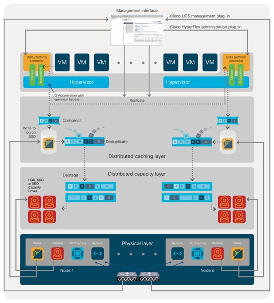
Cisco HyperFlex HX Data Platform Controller
A Cisco HyperFlex HX Data Platform controller resides on each node and implements the distributed file system. The controller runs as software in user space within a virtual machine, and intercepts and handles all I/O from the guest virtual machines. The Storage Controller Virtual Machine (SCVM) uses the VMDirectPath I/O feature to provide direct PCI passthrough control of the physical server’s SAS disk controller, or direct control of the PCI attached NVMe based SSDs. This method gives the controller VM full control of the physical disk resources, utilizing the SSD drives as a read/write caching layer, and the HDDs or SDDs as a capacity layer for distributed storage. The controller integrates the data platform into the VMware vSphere cluster through the use of three preinstalled VMware ESXi vSphere Installation Bundles (VIBs) on each node:
· IO Visor: This VIB provides a network file system (NFS) mount point so that the ESXi hypervisor can access the virtual disks that are attached to individual virtual machines. From the hypervisor’s perspective, it is simply attached to a network file system. The IO Visor intercepts guest VM IO traffic, and intelligently redirects it to the HyperFlex SCVMs.
· VMware API for Array Integration (VAAI): This storage offload API allows vSphere to request advanced file system operations such as snapshots and cloning. The controller implements these operations via manipulation of the filesystem metadata rather than actual data copying, providing rapid response, and thus rapid deployment of new environments.
· stHypervisorSvc: This VIB adds enhancements and features needed for HyperFlex data protection and VM replication.
Data Operations and Distribution
The Cisco HyperFlex HX Data Platform controllers handle all read and write operation requests from the guest VMs to their virtual disks (VMDK) stored in the distributed datastores in the cluster. The data platform distributes the data across multiple nodes of the cluster, and also across multiple capacity disks of each node, according to the replication level policy selected during the cluster setup. This method avoids storage hotspots on specific nodes, and on specific disks of the nodes, and thereby also avoids networking hotspots or congestion from accessing more data on some nodes versus others.
Replication Factor
The policy for the number of duplicate copies of each storage block is chosen during cluster setup and is referred to as the replication factor (RF).
· Replication Factor 3: For every I/O write committed to the storage layer, 2 additional copies of the blocks written will be created and stored in separate locations, for a total of 3 copies of the blocks. Blocks are distributed in such a way as to ensure multiple copies of the blocks are not stored on the same disks, nor on the same nodes of the cluster. This setting can tolerate simultaneous failures of 2 entire nodes in a cluster of 5 nodes or greater, without losing data and resorting to restore from backup or other recovery processes. RF3 is recommended for all production systems.
· Replication Factor 2: For every I/O write committed to the storage layer, 1 additional copy of the blocks written will be created and stored in separate locations, for a total of 2 copies of the blocks. Blocks are distributed in such a way as to ensure multiple copies of the blocks are not stored on the same disks, nor on the same nodes of the cluster. This setting can tolerate a failure of 1 entire node without losing data and resorting to restore from backup or other recovery processes. RF2 is suitable for non-production systems, or environments where the extra data protection is not needed. HyperFlex stretched clusters use the RF2 setting, however there are 2 copies of the data kept in both halves of the cluster, so effectively there are four copies stored.
Data Write and Compression Operations
Internally, the contents of each virtual disk are subdivided and spread across multiple servers by the HXDP software. For each write operation, the data is intercepted by the IO Visor module on the node where the VM is running, a primary node is determined for that particular operation via a hashing algorithm, and then sent to the primary node via the network. The primary node compresses the data in real time, writes the compressed data to the write log on its caching SSD, and replica copies of that compressed data are sent via the network and written to the write log on the caching SSD of the remote nodes in the cluster, according to the replication factor setting. For example, at RF=3 a write operation will be written to write log of the primary node for that virtual disk address, and two additional writes will be committed in parallel on two other nodes. Because the virtual disk contents have been divided and spread out via the hashing algorithm for each unique operation, this method results in all writes being spread across all nodes, avoiding the problems with data locality and “noisy” VMs consuming all the IO capacity of a single node. The write operation will not be acknowledged until all three copies are written to the caching layer SSDs. Written data is also cached in a write log area resident in memory in the controller VM, along with the write log on the caching SSDs. This process speeds up read requests when reads are requested of data that has recently been written.
Data Destaging and Deduplication
The Cisco HyperFlex HX Data Platform constructs multiple write log caching segments on the caching SSDs of each node in the distributed cluster. As write cache segments become full, and based on policies accounting for I/O load and access patterns, those write cache segments are locked and new writes roll over to a new write cache segment. The data in the now locked cache segment is destaged to the HDD capacity layer of the nodes for the Hybrid system or to the SSD capacity layer of the nodes for the All-Flash or All-NVMe systems. During the destaging process, data is deduplicated before being written to the capacity storage layer, and the resulting data can now be written to the HDDs or SDDs of the server. On hybrid systems, the now deduplicated and compressed data is also written to the dedicated read cache area of the caching SSD, which speeds up read requests of data that has recently been written. When the data is destaged to the capacity disks, it is written in a single sequential operation, avoiding disk head seek thrashing on the spinning disks and accomplishing the task in the minimal amount of time. Since the data is already deduplicated and compressed before being written, the platform avoids additional I/O overhead often seen on competing systems, which must later do a read/dedupe/compress/write cycle. Deduplication, compression and destaging take place with no delays or I/O penalties to the guest VMs making requests to read or write data, which benefits both the HDD and SDD configurations.
Data Read Operations
For data read operations, data may be read from multiple locations. For data that was very recently written, the data is likely to still exist in the write log of the local platform controller memory, or the write log of the local caching layer disk. If local write logs do not contain the data, the distributed filesystem metadata will be queried to see if the data is cached elsewhere, either in write logs of remote nodes, or in the dedicated read cache area of the local and remote caching SSDs of hybrid nodes. Finally, if the data has not been accessed in a significant amount of time, the filesystem will retrieve the requested data from the distributed capacity layer. As requests for reads are made to the distributed filesystem and the data is retrieved from the capacity layer, the caching SSDs of hybrid nodes populate their dedicated read cache area to speed up subsequent requests for the same data. This multi-tiered distributed system with several layers of caching techniques, ensures that data is served at the highest possible speed, leveraging the caching SSDs of the nodes fully and equally. All-flash and all-NVMe configurations do not employ a dedicated read cache, because such caching does not provide any performance benefit since the persistent data copy already resides on high-performance SSDs.
In summary, the Cisco HyperFlex HX Data Platform implements a distributed, log-structured file system that performs data operations via two configurations:
· In a Hybrid configuration, the data platform provides a caching layer using SSDs to accelerate read requests and write responses, and it implements a storage capacity layer using HDDs.
· In an All-Flash or all-NVMe configuration, the data platform provides a dedicated caching layer using high endurance SSDs to accelerate write responses, and it implements a storage capacity layer also using SSDs. Read requests are fulfilled directly from the capacity SSDs, as a dedicated read cache is not needed to accelerate read operations.
Requirements
The following sections detail the physical hardware, software revisions, and firmware versions required to install a single cluster of the Cisco HyperFlex system. This solution cluster will have a two-to-one ratio for Compute Only nodes to Converged Nodes. There are 16 Compute Only Nodes and 8 Converged Nodes for a total of 24 nodes.
Physical Components
Table 1 HyperFlex System Components
| Component |
Hardware Required |
| Fabric Interconnects |
Two Cisco UCS 6454 Fabric Interconnects |
| Servers |
Eight Cisco HyperFlex HXAF220c-M5SX All-Flash rack servers Sixteen Cisco B200-M5 Blade servers |
For complete server specifications and more information, please refer to the link below:
HXAF220c-M5SX Spec Sheet:
Table 2 lists the hardware component options for the HXAF220c-M5SX server model:
Table 2 HXAF220c-M5SX Server Options
| HXAF220c-M5SX options |
Hardware Required |
|
| Processors |
Chose a matching pair of 2nd Generation Intel Xeon 6230 Processor Scalable Family CPUs |
|
| Memory |
786 GB total memory using 64 GB DDR4 2933 MHz 1.2v modules depending on CPU type |
|
| Disk Controller |
Cisco 12Gbps Modular SAS HBA |
|
| SSDs |
Standard |
One 240 GB 2.5 Inch Enterprise Value 6G SATA SSD 1.6 TB 2.5 Inch Extreme Performance SAS SSD Six to eight 3.8 TB 2.5 Inch Enterprise Value 6G SATA SSDs, or six to eight 960 GB 2.5 Inch Enterprise Value 6G SATA SSDs |
| SED |
One 240 GB 2.5 Inch Enterprise Value 6G SATA SSD One 800 GB 2.5 Inch Enterprise Performance 12G SAS SED SSD Six to eight 3.8 TB 2.5 Inch Enterprise Value 6G SATA SED SSDs, or six to eight 960 GB 2.5 Inch Enterprise Value 6G SATA SED SSDs |
|
| Network |
Cisco UCS VIC 1457 VIC MLOM |
|
| Boot Device |
One 240 GB M.2 form factor SATA SSD |
|
| microSD Card |
One 32GB microSD card for local host utilities storage ( Not used in this study) |
|
| Optional |
|
|
Table 3 lists the hardware component options for the HX240c-M5L server model:
Table 3 Cisco UCS B200-M5 Server Options
| B200-M5 Options |
Hardware Required |
| Processors |
Chose a matching pair of 2nd Generation Intel Xeon Processor Scalable Family CPUs |
| Memory |
786 GB total memory using 64 GB DDR4 2933 MHz 1.2v modules depending on CPU type |
| Disk Controller |
Cisco 12Gbps Modular SAS HBA |
| SSDs |
One 240 GB 2.5 Inch Enterprise Value 6G SATA SSD One 3.2 TB 2.5 Inch Enterprise Performance 12G SAS SSD |
| HDDs |
Six to twelve 12 TB, 8 TB or 6 TB SAS 7.2K RPM LFF HDD |
| Network |
Cisco UCS VIC1457 VIC MLOM |
| Boot Device |
One 240 GB M.2 form factor SATA SSD |
| microSD Card |
One 32GB microSD card for local host utilities storage |
| Optional |
Cisco HyperFlex Acceleration Engine card |
Software Components
The software components of the Cisco HyperFlex system must meet minimum requirements for the Cisco UCS firmware, hypervisor version, and the Cisco HyperFlex Data Platform software in order to interoperate properly.
For additional hardware and software combinations, refer to the public Cisco UCS Hardware Compatibility webpage: https://ucshcltool.cloudapps.cisco.com/public/
Table 4 lists the software components and the versions required for the Cisco HyperFlex 4.0 system:
| Component |
Software Required |
| Hypervisor |
VMware ESXi 6.7 Update 3 CISCO Custom Image for ESXi 6.7 Update 3 for HyperFlex: HX-ESXi-6.7U3-15160138-Cisco-Custom-6.7.3.3-install-only.iso
|
| Management Server |
VMware vCenter Server for Windows or vCenter Server Appliance 6.0 U3c or later. Refer to http://www.vmware.com/resources/compatibility/sim/interop_matrix.php for interoperability of your ESXi version and vCenter Server.
|
| Cisco HyperFlex Data Platform |
Cisco HyperFlex HX Data Platform Software 4.0(2a) |
| Cisco UCS Firmware |
Cisco UCS Infrastructure software, B-Series and C-Series bundles, revision 4.0(4g) or later. |
Licensing
Cisco HyperFlex systems must be properly licensed using Cisco Smart Licensing, which is a cloud-based software licensing management solution used to automate many manual, time consuming and error prone licensing tasks. Cisco HyperFlex 2.5 and later communicate with the Cisco Smart Software Manager (CSSM) online service via a Cisco Smart Account, to check out or assign available licenses from the account to the Cisco HyperFlex cluster resources. Communications can be direct via the internet, they can be configured to communicate via a proxy server, or they can communicate with an internal Cisco Smart Software Manager satellite server, which caches and periodically synchronizes licensing data. In a small number of highly secure environments, systems can be provisioned with a Permanent License Reservation (PLR) which does not need to communicate with CSSM. Contact your Cisco sales representative or partner to discuss if your security requirements will necessitate use of these permanent licenses. New HyperFlex cluster installations will operate for 90 days without licensing as an evaluation period, thereafter the system will generate alarms and operate in a non-compliant mode. Systems without compliant licensing will not be entitled to technical support.
For more information on the Cisco Smart Software Manager satellite server, visit this website: https://www.cisco.com/c/en/us/buy/smart-accounts/software-manager-satellite.html
Beginning with Cisco HyperFlex 3.0, licensing of the system requires one license per node from one of three different licensing editions; Edge licenses, Standard licenses, or Enterprise licenses. Depending on the type of cluster being installed, and the desired features to be activated and used in the system, licenses must be purchased from the appropriate licensing tier. Additional features in the future will be added to the different licensing editions as they are released, the features listed below are current only as of the publication of this document.
Table 5 lists an overview of the licensing editions, and the features available with each type of license:
Table 5 HyperFlex System License Editions
| HyperFlex Licensing Edition |
Edge |
Standard (in addition to Edge) |
Enterprise (in addition to Standard) |
| Features Available |
HyperFlex Edge clusters without Fabric Interconnects 220 SFF model servers only Hybrid or All-Flash ESXi Hypervisor only Replication Factor 2 only 1 Gb or 10 Gb Ethernet only Compression Deduplication HyperFlex native snapshots Rapid Clones HyperFlex native replication Management via vCenter plugin, HyperFlex Connect, or Cisco Intersight |
HyperFlex standard clusters with Fabric Interconnects 220 and 240 SFF server models and 240 LFF server models Replication Factor 3 Hyper-V and Kubernetes platforms Cluster expansions Compute-only nodes up to 1:1 ratio 10 Gb, 25 Gb or 40 Gb Ethernet Data-at-rest encryption using self-encrypting disks Logical Availability Zones |
Stretched clusters 220 all-NVMe server models Cisco HyperFlex Acceleration Engine cards Compute-only nodes up to 2:1 ratio |
For a comprehensive guide to licensing and all the features in each edition, consult the Cisco HyperFlex Licensing Guide here: https://www.cisco.com/c/en/us/td/docs/hyperconverged_systems/HyperFlex_HX_DataPlatformSoftware/b_Cisco_HyperFlex_Systems_Ordering_and_Licensing_Guide/b_Cisco_HyperFlex_Systems_Ordering_and_Licensing_Guide_chapter_01001.html
Physical Topology
Topology Overview
The Cisco HyperFlex system is composed of a pair of Cisco UCS Fabric Interconnects along with up to thirty-two HX-Series rack-mount servers per cluster. Up to thirty-two compute-only servers can also be added per HyperFlex cluster. Adding Cisco UCS rack-mount servers and/or Cisco UCS 5108 Blade chassis, which house Cisco UCS blade servers, allows for additional compute resources in an extended cluster design. The two Fabric Interconnects both connect to every HX-Series rack-mount server, and both connect to every Cisco UCS 5108 blade chassis, and Cisco UCS rack-mount server. Upstream network connections, also referred to as “northbound” network connections are made from the fabric interconnects to the customer datacenter network at the time of installation.
Fabric Interconnects
Fabric Interconnects (FI) are deployed in pairs, wherein the two units operate as a management cluster, while forming two separate network fabrics, referred to as the A side and B side fabrics. Therefore, many design elements will refer to FI A or FI B, alternatively called fabric A or fabric B. Both Fabric Interconnects are active at all times, passing data on both network fabrics for a redundant and highly available configuration. Management services, including Cisco UCS Manager, are also provided by the two FIs but in a clustered manner, where one FI is the primary, and one is secondary, with a roaming clustered IP address. This primary/secondary relationship is only for the management cluster and has no effect on data transmission.
Fabric Interconnects have the following ports, which must be connected for proper management of the Cisco UCS domain:
· Mgmt: A 10/100/1000 Mbps port for managing the Fabric Interconnect and the Cisco UCS domain via GUI and CLI tools. This port is also used by remote KVM, IPMI and SoL sessions to the managed servers within the domain. This is typically connected to the customer management network.
· L1: A cross connect port for forming the Cisco UCS management cluster. This port is connected directly to the L1 port of the paired Fabric Interconnect using a standard CAT5 or CAT6 Ethernet cable with RJ45 plugs. It is not necessary to connect this to a switch or hub.
· L2: A cross connect port for forming the Cisco UCS management cluster. This port is connected directly to the L2 port of the paired Fabric Interconnect using a standard CAT5 or CAT6 Ethernet cable with RJ45 plugs. It is not necessary to connect this to a switch or hub.
· Console: An RJ45 serial port for direct console access to the Fabric Interconnect. This port is typically used during the initial FI setup process with the included serial to RJ45 adapter cable. This can also be plugged into a terminal aggregator or remote console server device.
HX-Series Rack-Mount Servers
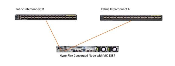
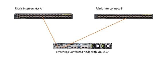
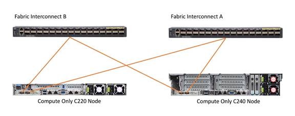
The HX-Series converged servers are connected directly to the Cisco UCS Fabric Interconnects in Direct Connect mode. This option enables Cisco UCS Manager to manage the HX-Series Rack-Mount Servers using a single cable for both management traffic and data traffic. Cisco HyperFlex M5 generation servers can be configured with the Cisco VIC 1387 or VIC 1457 cards. The standard and redundant connection practice for the VIC 1387 is to connect port 1 of the VIC card (the right-hand port) to a port on FI A, and port 2 of the VIC card (the left-hand port) to a port on FI B (Figure 11). For the VIC 1457 card, the standard and redundant practice is to connect port 1 of the VIC card (the left-hand most port) to a port on FI A, and connect port 3 (the right-center port) to a port on FI B (Figure 12). An optional configuration method for servers containing the Cisco VIC 1457 card is to cable the servers with 2 links to each FI, using ports 1 and 2 to FI A, and ports 3 and 4 to FI B. The HyperFlex installer checks for these configurations, and that all servers’ cabling matches. Failure to follow this cabling best practice can lead to errors, discovery failures, and loss of redundant connectivity.
All nodes within a Cisco HyperFlex cluster must be connected at the same communication speed, for example, mixing 10 Gb with 25 Gb interfaces is not allowed. In addition, for clusters that contain only M5 generation nodes, all of the nodes within a cluster must contain the same model of Cisco VIC cards.
Various combinations of physical connectivity between the Cisco HX-series servers and the Fabric Interconnects are possible, but only specific combinations are supported. Table 6 lists the possible connections, and which of these methods is supported.
Table 6 Supported Physical Connectivity
| Fabric Interconnect Model |
6248 |
6296 |
6332 |
6332-16UP |
6454 |
||||
| Port Type |
10GbE |
10GbE |
40GbE |
10GbE Breakout |
40GbE |
10GbE Breakout |
10GbE onboard |
10GbE |
25GbE |
| M4 with VIC 1227 |
✓ |
✓ |
✕ |
✕ |
✕ |
✕ |
✕ |
✓ |
✕ |
| M4 with VIC 1387 |
✕ |
✕ |
✓ |
✕ |
✓ |
✕ |
✕ |
✕ |
✕ |
| M4 with VIC 1387 + QSA |
✓ |
✓ |
✕ |
✕ |
✕ |
✕ |
✕ |
✓ |
✕ |
| M5 with VIC 1387 |
✕ |
✕ |
✓ |
✕ |
✓ |
✕ |
✕ |
✕ |
✕ |
| M5 with VIC 1387 + QSA |
✓ |
✓ |
✕ |
✕ |
✕ |
✕ |
✕ |
✓ |
✕ |
| M5 with VIC 1457 |
✓ |
✓ |
✕ |
✕ |
✕ |
✕ |
✕ |
✓ |
✓ |
Cisco UCS B-Series Blade Servers
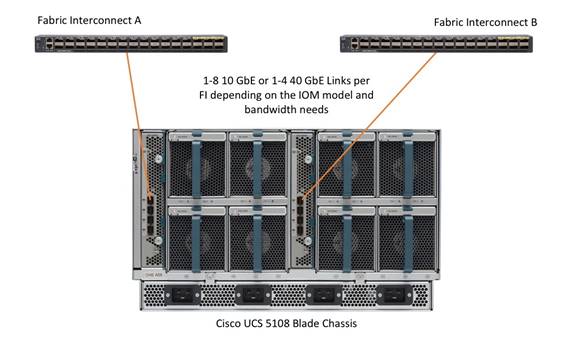
HyperFlex extended clusters can also incorporate 1-32 Cisco UCS blade servers for additional compute capacity. The blade chassis comes populated with 1-4 power supplies, and 8 modular cooling fans. In the rear of the chassis are two bays for installation of Cisco Fabric Extenders. The Fabric Extenders (also commonly called IO Modules, or IOMs) connect the chassis to the Fabric Interconnects. Internally, the Fabric Extenders connect to the Cisco VIC card installed in each blade server across the chassis backplane. The standard connection practice is to connect 1-8 10 GbE links, or 1-4 40 GbE links (depending on the IOMs and FIs purchased) from the left-side IOM, or IOM 1, to FI A, and to connect the same number of 10 GbE or 40 GbE links from the right-side IOM, or IOM 2, to FI B (Figure 14). All other cabling configurations are invalid, and can lead to errors, discovery failures, and loss of redundant connectivity.
Cisco UCS C-Series Rack-Mount Servers
HyperFlex extended clusters can also incorporate 1-32 Cisco UCS Rack-Mount Servers for additional compute capacity. The Cisco UCS C-Series Rack-Mount Servers are connected directly to the Cisco UCS Fabric Interconnects in Direct Connect mode. Internally the Cisco UCS C-Series servers are configured with the Cisco VIC 1227, 1387 or 1457 network interface card (NIC) installed in a modular LAN on motherboard (MLOM) slot, which have dual 10 Gigabit Ethernet (GbE), quad 10/25 Gigabit Ethernet (GbE) ports or dual 40 Gigabit Ethernet (GbE) ports. The standard and redundant connection practice for connecting standard Cisco UCS C-Series servers to the Fabric Interconnects is identical to the method described earlier for the HX-Series servers. Failure to follow this cabling practice can lead to errors, discovery failures, and loss of redundant connectivity.
Logical Topology
Logical Network Design
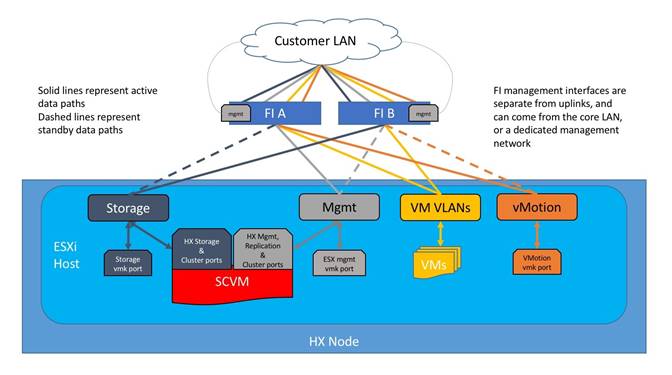
The Cisco HyperFlex system has communication pathways that fall into four defined zones (Figure 16):
· Management Zone: This zone comprises the connections needed to manage the physical hardware, the hypervisor hosts, and the storage platform controller virtual machines (SCVM). These interfaces and IP addresses need to be available to all staff who will administer the HX system, throughout the LAN/WAN. This zone must provide access to Domain Name System (DNS) and Network Time Protocol (NTP) services, and also allow Secure Shell (SSH) communication. In this zone are multiple physical and virtual components:
- Fabric Interconnect management ports.
- Cisco UCS external management interfaces used by the servers and blades, which answer via the FI management ports.
- ESXi host management interfaces.
- Storage Controller VM management interfaces.
- A roaming HX cluster management interface.
- Storage Controller VM replication interfaces.
- A roaming HX cluster replication interface.
· VM Zone: This zone comprises the connections needed to service network IO to the guest VMs that will run inside the HyperFlex hyperconverged system. This zone typically contains multiple VLANs, which are trunked to the Cisco UCS Fabric Interconnects via the network uplinks and tagged with 802.1Q VLAN IDs. These interfaces and IP addresses need to be available to all staff and other computer endpoints which need to communicate with the guest VMs in the HX system, throughout the LAN/WAN.
· Storage Zone: This zone comprises the connections used by the Cisco HX Data Platform software, ESXi hosts, and the storage controller VMs to service the HX Distributed Data Filesystem. These interfaces and IP addresses need to be able to communicate with each other at all times for proper operation. During normal operation, this traffic all occurs within the Cisco UCS domain, however there are hardware failure scenarios where this traffic would need to traverse the network northbound of the Cisco UCS domain. For that reason, the VLAN used for HX storage traffic must be able to traverse the network uplinks from the Cisco UCS domain, reaching FI A from FI B, and vice-versa. This zone is primarily jumbo frame traffic therefore jumbo frames must be enabled on the Cisco UCS uplinks. In this zone are multiple components:
- A VMkernel interface used for storage traffic on each ESXi host in the HX cluster.
- Storage Controller VM storage interfaces.
- A roaming HX cluster storage interface.
· VMotion Zone: This zone comprises the connections used by the ESXi hosts to enable vMotion of the guest VMs from host to host. During normal operation, this traffic all occurs within the Cisco UCS domain, however there are hardware failure scenarios where this traffic would need to traverse the network northbound of the Cisco UCS domain. For that reason, the VLAN used for HX vMotion traffic must be able to traverse the network uplinks from the Cisco UCS domain, reaching FI A from FI B, and vice-versa.
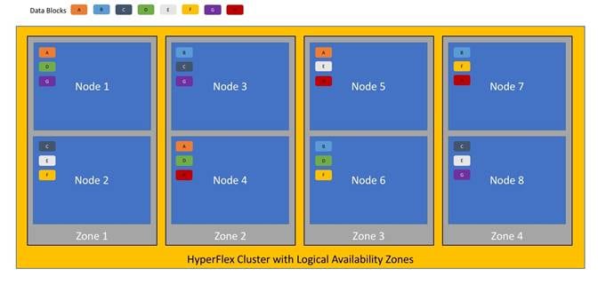
Logical Availability Zones
Larger scale HyperFlex clusters are subject to higher failure risks, simply due to the number of nodes in the cluster. While any individual node’s risk of failure is the same no matter how many nodes there are, with clusters up to 32 converged nodes in size, there is a logically higher probability that a single node could fail, when compared to a cluster with fewer nodes. To mitigate these risks in larger scale clusters, a HyperFlex cluster of eight nodes or more can be configured with a feature called Logical Availability Zones (LAZ). The Logical Availability Zones feature groups 2 or more HyperFlex nodes together into a logically defined zone, a minimum of 3 zones are created, and the data in the cluster is distributed in such a way that no blocks are written to the nodes within a single zone more than once. Due to this enhanced distribution pattern of data across zones, wherein each zone has multiple servers, clusters with LAZ enabled can typically withstand more failures than clusters which operate without it. The number of failures that can tolerated varies depending on the number of zones in the cluster, and the number of servers in each of the zones. Generally speaking, multiple node failures across one or two zones will be tolerated better, and with less risk than multiple nodes failing across three or more zones. Note that the failure tolerance shown in the HyperFlex Connect dashboard will always present a “worst case scenario” view, meaning that even though the dashboard may state that two failures can be tolerated, in fact two servers could fail and the cluster can remain online, and the failure tolerance may still remain at two.
Logical availability zones should not be confused with the concept of fault domains. An example of a fault domain would be a subset of the nodes in a single HyperFlex cluster being powered by one uninterruptable power supply (UPS) or connected to one power distribution unit (PDU), meanwhile the remaining nodes would be connected to another UPS or PDU. If one of the UPS’ or PDUs were to fail, then there would be a simultaneous failure of multiple nodes. While LAZ may actually prevent the cluster from failing in this scenario, to guarantee it would require that the zone membership be manually controlled, so that a failure of all of the servers protected by a single UPS or PDU, would be distributed in such a way that it would not cause an outage. The LAZ feature is not designed to be manually configured in this way, instead the zone membership is determined automatically by the system. If a HyperFlex cluster needs to be physically split in half due to a physical limitation, such as the UPS example above, or a distance requirement for fault tolerance, then the cluster should be built as a stretched cluster instead of using LAZ.
Figure 17 illustrates an example of the data distribution method for clusters with Logical Availability Zones enabled, set to replication factor 3, where each zone only contains one of the three copies of the data in the cluster. This cluster consists of eight nodes, which the system configures into four zones.
Logical availability zones are subject to the following requirements and limitations:
· Only HyperFlex clusters with 8 nodes or more can be configured with logical availability zones during the installation process.
· Logical Availability Zones can be enabled during the HyperFlex cluster installation, or it can be enabled via the command line at a later time. It is recommended to enable this feature during installation, in order to avoid a large migration and reorganization of data across the cluster, which would be necessary to comply with the data distribution rules if LAZ is turned on in a cluster already containing data.
· The number of zones can be manually specified as 3, 4, 5, or you can allow the installer to automatically choose, which is the recommended setting.
· The HyperFlex cluster determines which nodes participate in each zone, and this configuration cannot be modified.
· To maintain the most balanced consumption of space and data distribution, it is recommended that the number of nodes in a cluster are whole multiples of 3, 4, 5, or 7. For example, 8 nodes would evenly divide into 4 zones of 2 servers each, and 9 nodes would divide evenly into 3 zones of 3 servers each. Eleven nodes would create an unbalanced number of nodes across the zones, leading to unbalanced space consumption on the nodes.
· In addition to the previous point, expansion of a cluster should be done in multiples of the number of zones, when the cluster is operating with LAZ enabled. Expanding in such a way preserves a matched number of nodes in each zone and prevents any unbalance of space consumption. For example, a cluster with 3 zones should be expanded by adding 3 more nodes, because adding only 1 or 2 nodes would lead to an imbalance, as would adding 4 nodes.
Considerations
Version Control
The software revisions listed in Table 4 are the only valid and supported configuration at the time of the publishing of this validated design. Special care must be taken not to alter the revision of the hypervisor, vCenter server, Cisco HX platform software, or the Cisco UCS firmware without first consulting the appropriate release notes and compatibility matrixes to ensure that the system is not being modified into an unsupported configuration.
vCenter Server
VMware vCenter Server 6.0 Update 3c or later is required due to the requirement for TLS 1.2 with Cisco HyperFlex 4.0. The following best practice guidance applies to installations of HyperFlex 4.0:
· Do not modify the default TCP port settings of the vCenter installation. Using non-standard ports can lead to failures during the installation.
· It is recommended to build the vCenter server on a physical server or in a virtual environment outside of the HyperFlex cluster. Building the vCenter server as a virtual machine inside the HyperFlex cluster environment is highly discouraged. There is a tech note for multiple methods of deployment if no external vCenter server is already available: http://www.cisco.com/c/en/us/td/docs/hyperconverged_systems/HyperFlex_HX_DataPlatformSoftware/TechNotes/Nested_vcenter_on_hyperflex.html
![]() Note: This document does not cover the installation and configuration of VMware vCenter Server for Windows, or the vCenter Server Appliance.
Note: This document does not cover the installation and configuration of VMware vCenter Server for Windows, or the vCenter Server Appliance.
Scale
Cisco HyperFlex standard clusters currently scale from a minimum of 3 to a maximum of 32 Cisco HX-series converged nodes with small form factor (SFF) disks per cluster. A converged node is a member of the cluster which provides storage resources to the HX Distributed Filesystem. For the compute intensive “extended” cluster design, a configuration with 3 to 32 Cisco HX-series converged nodes can be combined with up to 32 compute nodes. It is required that the number of compute-only nodes should always be less than or equal to number of converged nodes when using the HyperFlex Standard licenses. If using HyperFlex Enterprise licenses, the number of compute-only nodes can grow to as much as twice the number of converged nodes. Regardless of the licensing used, the combined maximum size of any HyperFlex cluster cannot exceed 64 nodes. Once the maximum size of a single cluster has been reached, the environment can be “scaled out” by adding additional HX model servers to the Cisco UCS domain, installing an additional HyperFlex cluster on them, and controlling them via the same vCenter server. There is no longer any limit to the number of clusters that can be created in a single UCS domain, the practical limits will instead be reached due to the number of ports available on the Fabric Interconnects. Up to 100 HyperFlex clusters can be managed by a single vCenter server. When using Cisco Intersight for management and monitoring of Cisco HyperFlex clusters, there are no practical limits to the number of clusters being managed.
Cisco HyperFlex All-NVMe HXAF220c-M5N model servers are limited to a maximum of sixteen nodes per cluster and are not allowed to deploy more compute-only nodes than converged nodes, regardless of licensing.
Cisco HyperFlex HX240c-M5L model servers with large form factor (LFF) disks are limited to a maximum of sixteen nodes per cluster and cannot be mixed within the same cluster as models with small form factor (SFF) disks. In the case where the HX240c-M5L nodes use the 12 TB capacity disks, the maximum number of converged nodes is limited to 8.
Cisco HyperFlex systems deployed in a stretched cluster configuration require a minimum of two Cisco HX-series converged nodes per physical site and support a maximum of sixteen converged nodes per physical site when using small-form-factor (SFF) disks. When using large-form-factor (LFF) disks, the maximum number of converged nodes allowed in a stretched cluster is 8. Each site requires a pair of Cisco UCS Fabric Interconnects, to form an individual UCS domain in both sites.
Table 7 lists the minimum and maximum scale for various installations of the Cisco HyperFlex system.
Table 7 HyperFlex Cluster Scale
| Cluster Type |
Minimum Converged Nodes Required |
Maximum Converged Nodes |
Maximum Compute-only Nodes Allowed |
Maximum Total Cluster Size |
| Standard with SFF disks |
3 |
32 |
32 |
64 |
| Standard with LFF disks |
3 |
16 |
32 |
48 |
| Standard with 12 TB LFF disks |
3 |
8 |
16 |
24 |
| Standard with all-NVMe disks |
3 |
16 |
16 |
32 |
| Stretched with SFF disks |
2 per site |
16 per site |
21 per site |
32 per site 64 per cluster |
| Stretched with LFF disks |
2 per site |
8 per site |
16 per site |
24 per site 48 per cluster |
Capacity
Overall usable cluster capacity is based on a number of factors. The number of nodes in the cluster, the number and size of the capacity layer disks, and the replication factor of the HyperFlex HX Data Platform, all affect the cluster capacity. In addition, configuring a cluster as a stretched cluster across two sites modifies the data distribution method, which reduces capacity in favor of data availability. Caching disk sizes are not calculated as part of the cluster capacity.
Disk drive manufacturers have adopted a size reporting methodology using calculation by powers of 10, also known as decimal prefix. As an example, a 120 GB disk is listed with a minimum of 120 x 10^9 bytes of usable addressable capacity, or 120 billion bytes. However, many operating systems and filesystems report their space based on standard computer binary exponentiation, or calculation by powers of 2, also called binary prefix. In this example, 2^10 or 1024 bytes make up a kilobyte, 2^10 kilobytes make up a megabyte, 2^10 megabytes make up a gigabyte, and 2^10 gigabytes make up a terabyte. As the values increase, the disparity between the two systems of measurement and notation get worse, at the terabyte level, the deviation between a decimal prefix value and a binary prefix value is nearly 10 percent.
The International System of Units (SI) defines values and decimal prefix by powers of 10 as follows:
Table 8 SI Unit Values (Decimal Prefix)
| Value |
Symbol |
Name |
| 1000 bytes |
kB |
Kilobyte |
| 1000 kB |
MB |
Megabyte |
| 1000 MB |
GB |
Gigabyte |
| 1000 GB |
TB |
Terabyte |
The International Organization for Standardization (ISO) and the International Electrotechnical Commission (IEC) defines values and binary prefix by powers of 2 in ISO/IEC 80000-13:2008 Clause 4 as follows:
Table 9 IEC Unit Values (binary prefix)
| Value |
Symbol |
Name |
| 1024 bytes |
KiB |
Kibibyte |
| 1024 KiB |
MiB |
Mebibyte |
| 1024 MiB |
GiB |
Gibibyte |
| 1024 GiB |
TiB |
Tebibyte |
For the purpose of this document, the decimal prefix numbers are used only for raw disk capacity as listed by the respective manufacturers. For all calculations where raw or usable capacities are shown from the perspective of the HyperFlex software, filesystems or operating systems, the binary prefix numbers are used. This is done primarily to show a consistent set of values as seen by the end user from within the HyperFlex vCenter Web Plugin and HyperFlex Connect GUI when viewing cluster capacity, allocation and consumption, and also within most operating systems.
Table 10 lists a set of HyperFlex HX Data Platform cluster usable capacity values, using binary prefix, for an array of cluster configurations. These values provide an example of the capacity calculations, for determining the appropriate size of HX cluster to initially purchase, and how much capacity can be gained by adding capacity disks.
Table 10 Cluster Usable Capacities
| HX-Series Server Model |
Node Quantity |
Capacity Disk Size (each) |
Capacity Disk Quantity (per node) |
Cluster Usable Capacity at RF=2 |
Cluster Usable Capacity at RF=3 |
| HXAF220c-M5SX |
8 |
3.8 TB |
8 |
102.8 TiB |
68.6 TiB |
| 960 GB |
8 |
25.7 TiB |
17.1 TiB |
||
| 800 GB |
8 |
21.4 TiB |
14.3 TiB |
||
| HXAF240c-M5SX |
8 |
3.8 TB |
6 |
77.1 TiB |
51.4 TiB |
| 15 |
192.8 TiB |
128.5 TiB |
|||
| 23 |
295.7 TiB |
197.1 TiB |
|||
| 960 GB |
6 |
19.3 TiB |
12.9 TiB |
||
| 15 |
48.2 TiB |
32.1 TiB |
|||
| 23 |
73.9 TiB |
49.3 TiB |
|||
| 800 GB |
6 |
16.1 TiB |
10.7 TiB |
||
| 15 |
40.2 TiB |
26.8 TiB |
|||
| 22 |
58.9 TiB |
39.3 TiB |
|||
| HX240c-M5L |
8 |
6 TB |
6 |
120.5 TiB |
80.3 TiB |
| 12 |
241.0 TiB |
160.7 TiB |
|||
| 8 TB |
6 |
160.7 TiB |
107.1 TiB |
||
| 12 |
321.3 TiB |
214.2 TiB |
![]() Note: Capacity calculations methods for all servers are identical regardless of model. Calculations are based upon the number of nodes, the number of capacity disks per node, and the size of the capacity disks. The above table is not a comprehensive list of all capacities and models available.
Note: Capacity calculations methods for all servers are identical regardless of model. Calculations are based upon the number of nodes, the number of capacity disks per node, and the size of the capacity disks. The above table is not a comprehensive list of all capacities and models available.
Installing the HyperFlex system is done via the Cisco Intersight online management portal, or through a deployable HyperFlex installer virtual machine, available for download at cisco.com as an OVA file. The installer performs most of the Cisco UCS configuration work, and also performs significant portions of the ESXi configuration. Finally, the installer will install the HyperFlex HX Data Platform software and create the HyperFlex cluster. Because this simplified installation method has been developed by Cisco, this CVD will not give detailed manual steps for the configuration of all the elements that are handled by the installer. Instead, the elements configured will be described and documented in this section, and the subsequent sections will guide you through the manual prerequisite steps needed for installation, and how to then utilize the HyperFlex Installer for the remaining configuration steps. This document focuses on the use of Cisco Intersight for the initial deployment of a Cisco HyperFlex cluster.
Network Design
Cisco UCS Uplink Connectivity
Cisco UCS network uplinks connect “northbound” from the pair of Cisco UCS Fabric Interconnects to the LAN in the customer datacenter. All Cisco UCS uplinks operate as trunks, carrying multiple 802.1Q VLAN IDs across the uplinks. The default Cisco UCS behavior is to assume that all VLAN IDs defined in the Cisco UCS configuration are eligible to be trunked across all available uplinks.
Cisco UCS Fabric Interconnects appear on the network as a collection of endpoints versus another network switch. Internally, the Fabric Interconnects do not participate in spanning-tree protocol (STP) domains, and the Fabric Interconnects cannot form a network loop, as they are not connected to each other with a layer 2 Ethernet link. All link up/down decisions via STP will be made by the upstream root bridges.
Uplinks need to be connected and active from both Fabric Interconnects. For redundancy, multiple uplinks can be used on each FI, either as 802.3ad Link Aggregation Control Protocol (LACP) port-channels or using individual links. For the best level of performance and redundancy, uplinks can be made as LACP port-channels to multiple upstream Cisco switches using the virtual port channel (vPC) feature. Using vPC uplinks allows all uplinks to be active passing data, plus protects against any individual link failure, and the failure of an upstream switch. Other uplink configurations can be redundant, however spanning-tree protocol loop avoidance may disable links if vPC is not available.
All uplink connectivity methods must allow for traffic to pass from one Fabric Interconnect to the other, or from fabric A to fabric B. There are scenarios where cable, port or link failures would require traffic that normally does not leave the Cisco UCS domain, to instead be directed over the Cisco UCS uplinks because that traffic must travel from fabric A to fabric B, or vice-versa. Additionally, this traffic flow pattern can be seen briefly during maintenance procedures, such as updating firmware on the Fabric Interconnects, which requires them to be rebooted. Cisco recommends that the uplink bandwidth configured is greater than or equal to double the bandwidth available to each Hyperflex converged node. For example, if the nodes are connected at 10 Gigabit speeds, then each Fabric Interconnect should have at least 20 Gigabit of uplink bandwidth available. The following sections and figures detail several uplink connectivity options.
Single Uplinks to Single Switch
This connection design is susceptible to failures at several points; single uplink failures on either Fabric Interconnect can lead to connectivity losses or functional failures, and the failure of the single uplink switch will cause a complete connectivity outage.
Port Channels to Single Switch
This connection design is now redundant against the loss of a single link but remains susceptible to the failure of the single switch.
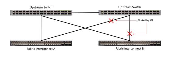
Single Uplinks or Port Channels to Multiple Switches
This connection design is redundant against the failure of an upstream switch, and redundant against a single link failure. In normal operation, STP is likely to block half of the links to avoid a loop across the two upstream switches. The side effect of this is to reduce bandwidth between the Cisco UCS domain and the LAN. If any of the active links were to fail, STP would bring the previously blocked link online to provide access to that Fabric Interconnect via the other switch. It is not recommended to connect both links from a single FI to a single switch, as that configuration is susceptible to a single switch failure breaking connectivity from fabric A to fabric B. For enhanced redundancy, the single links in the figure below could also be port-channels.
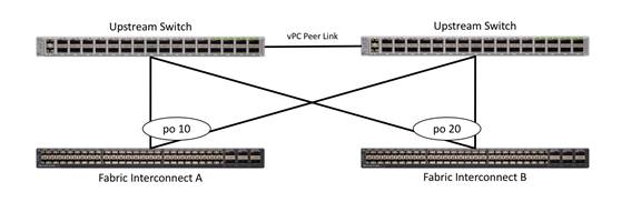
vPC to Multiple Switches
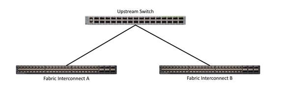
This recommended connection design relies on using Cisco switches that have the virtual port channel feature, such as Catalyst 6000 series switches running VSS, Cisco Nexus 5000 series, and Cisco Nexus 9000 series switches. Logically the two vPC enabled switches appear as one, and therefore spanning-tree protocol will not block any links. This configuration allows for all links to be active, achieving maximum bandwidth potential, and multiple redundancy at each level.
VLANs and Subnets
For the base HyperFlex system configuration, multiple VLANs need to be carried to the Cisco UCS domain from the upstream LAN, and these VLANs are also defined in the Cisco UCS configuration. The hx-storage-data VLAN must be a separate VLAN ID from the remaining VLANs. Table 11 lists the VLANs created by the HyperFlex installer in Cisco UCS, and their functions:
| VLAN Name |
VLAN ID |
Purpose |
| hx-inband-mgmt |
Customer supplied |
ESXi host management interfaces HX Storage Controller VM management interfaces HX Storage Cluster roaming management interface |
| hx-inband-repl |
Customer supplied |
HX Storage Controller VM Replication interfaces HX Storage Cluster roaming replication interface |
| hx-storage-data |
Customer supplied |
ESXi host storage VMkernel interfaces HX Storage Controller storage network interfaces HX Storage Cluster roaming storage interface |
| vm-network |
Customer supplied |
Guest VM network interfaces |
| hx-vmotion |
Customer supplied |
ESXi host vMotion VMkernel interfaces |
![]() Note: A dedicated network or subnet for physical device management is often used in data centers. In this scenario, the mgmt0 interfaces of the two Fabric Interconnects would be connected to that dedicated network or subnet. This is a valid configuration for HyperFlex installations with the following caveat; wherever the HyperFlex installer is deployed it must have IP connectivity to the subnet of the mgmt0 interfaces of the Fabric Interconnects, and also have IP connectivity to the subnets used by the hx-inband-mgmt VLANs listed above.
Note: A dedicated network or subnet for physical device management is often used in data centers. In this scenario, the mgmt0 interfaces of the two Fabric Interconnects would be connected to that dedicated network or subnet. This is a valid configuration for HyperFlex installations with the following caveat; wherever the HyperFlex installer is deployed it must have IP connectivity to the subnet of the mgmt0 interfaces of the Fabric Interconnects, and also have IP connectivity to the subnets used by the hx-inband-mgmt VLANs listed above.
Jumbo Frames
All HyperFlex storage traffic traversing the hx-storage-data VLAN and subnet is configured by default to use jumbo frames, or to be precise, all communication is configured to send IP packets with a Maximum Transmission Unit (MTU) size of 9000 bytes. In addition, the default MTU for the hx-vmotion VLAN is also set to use jumbo frames. Using a larger MTU value means that each IP packet sent carries a larger payload, therefore transmitting more data per packet, and consequently sending and receiving data faster. This configuration also means that the Cisco UCS uplinks must be configured to pass jumbo frames. Failure to configure the Cisco UCS uplink switches to allow jumbo frames can lead to service interruptions during some failure scenarios, including Cisco UCS firmware upgrades, or when a cable or port failure would cause storage traffic to traverse the northbound Cisco UCS uplink switches.
HyperFlex clusters can be configured to use standard size frames of 1500 bytes, however Cisco recommends that this configuration only be used in environments where the Cisco UCS uplink switches are not capable of passing jumbo frames, and that jumbo frames be enabled in all other situations.
Cisco UCS Design
This section describes the elements within Cisco UCS Manager that are configured by the Cisco HyperFlex installer. Many of the configuration elements are fixed in nature, meanwhile the HyperFlex installer does allow for some items to be specified at the time of creation, for example VLAN names and IDs, external management IP pools and more. Where the elements can be manually set during the installation, those items will be noted in << >> brackets.
Cisco UCS Organization
During the HyperFlex installation a new Cisco UCS sub-organization is created. The sub-organization is created underneath the root level of the Cisco UCS hierarchy, and is used to contain all policies, pools, templates and service profiles used by HyperFlex, which prevents problems from overlapping settings across policies and pools. This arrangement also allows for organizational control using Role-Based Access Control (RBAC) and administrative locales within Cisco UCS Manager at a later time if desired. In this way, control can be granted to administrators of only the HyperFlex specific elements of the Cisco UCS domain, separate from control of root level elements or elements in other sub-organizations.
Cisco UCS LAN Policies
QoS System Classes
Specific Cisco UCS Quality of Service (QoS) system classes are defined for a Cisco HyperFlex system. These classes define Class of Service (CoS) values that can be used by the uplink switches north of the Cisco UCS domain, plus which classes are active, along with whether packet drop is allowed, the relative weight of the different classes when there is contention, the maximum transmission unit (MTU) size, and if there is multicast optimization applied. QoS system classes are defined for the entire Cisco UCS domain, the classes that are enabled can later be used in QoS policies, which are then assigned to Cisco UCS vNICs. The following table and figure details the QoS System Class settings configured for HyperFlex:
| Priority |
Enabled |
CoS |
Packet Drop |
Weight |
MTU |
Multicast Optimized |
| Platinum |
Yes |
5 |
No |
4 |
9216 |
No |
| Gold |
Yes |
4 |
Yes |
4 |
Normal |
No |
| Silver |
Yes |
2 |
Yes |
Best-effort |
Normal |
Yes |
| Bronze |
Yes |
1 |
Yes |
Best-effort |
9216 |
No |
| Best Effort |
Yes |
Any |
Yes |
Best-effort |
Normal |
No |
| Fibre Channel |
Yes |
3 |
No |
5 |
FC |
N/A |
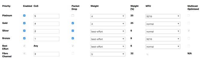
![]() Note: Changing the QoS system classes on a Cisco UCS 6332 or 6332-16UP model Fabric Interconnect requires both FIs to reboot in order to take effect.
Note: Changing the QoS system classes on a Cisco UCS 6332 or 6332-16UP model Fabric Interconnect requires both FIs to reboot in order to take effect.
QoS Policies
In order to apply the settings defined in the Cisco UCS QoS System Classes, specific QoS Policies must be created, and then assigned to the vNICs, or vNIC templates used in Cisco UCS Service Profiles. Table 13 details the QoS Policies configured for HyperFlex, and their default assignment to the vNIC templates created:
Table 13 HyperFlex QoS Policies
| Policy |
Priority |
Burst |
Rate |
Host Control |
Used by vNIC Template |
| Platinum |
Platinum |
10240 |
Line-rate |
None |
storage-data-a storage-data-b |
| Gold |
Gold |
10240 |
Line-rate |
None |
vm-network-a vm-network-b |
| Silver |
Silver |
10240 |
Line-rate |
None |
hv-mgmt-a hv-mgmt-b |
| Bronze |
Bronze |
10240 |
Line-rate |
None |
hv-vmotion-a hv-vmotion-b |
| Best Effort |
Best Effort |
10240 |
Line-rate |
None |
N/A |
Multicast Policy
A Cisco UCS Multicast Policy is configured by the HyperFlex installer, which is referenced by the VLANs that are created. The policy allows for future flexibility if a specific multicast policy needs to be created and applied to other VLANs, that may be used by non-HyperFlex workloads in the Cisco UCS domain. Table 14 and Figure 24 detail the Multicast Policy configured for HyperFlex:
| Name |
IGMP Snooping State |
IGMP Snooping Querier State |
| HyperFlex |
Enabled |
Disabled |
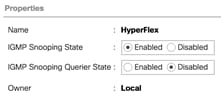
VLANs
VLANs are created by the HyperFlex installer to support a base HyperFlex system, with a VLAN for vMotion, and a single or multiple VLANs defined for guest VM traffic. Names and IDs for the VLANs are defined in the Cisco UCS configuration page of the HyperFlex installer web interface. The VLANs listed in Cisco UCS must already be present on the upstream network, and the Cisco UCS FIs do not participate in VLAN Trunk Protocol (VTP). Table 15 details the VLANs configured for HyperFlex:
| Name |
ID |
Type |
Transport |
Native |
VLAN Sharing |
Multicast Policy |
| <<hx-inband-mgmt>> |
<<user_defined>> |
LAN |
Ether |
No |
None |
HyperFlex |
| <<hx-inband-repl>> |
<<user_defined>> |
LAN |
Ether |
No |
None |
HyperFlex |
| <<hx-storage-data>> |
<<user_defined>> |
LAN |
Ether |
No |
None |
HyperFlex |
| <<vm-network>> |
<<user_defined>> |
LAN |
Ether |
No |
None |
HyperFlex |
| <<hx-vmotion>> |
<<user_defined>> |
LAN |
Ether |
No |
None |
HyperFlex |
Management IP Address Pool
A Cisco UCS Management IP Address Pool must be populated with a block of IP addresses. These IP addresses are assigned to the Cisco Integrated Management Controller (CIMC) interface of the rack mount and blade servers that are managed in the Cisco UCS domain. The IP addresses are the communication endpoints for various functions, such as remote KVM, virtual media, Serial over LAN (SoL), and Intelligent Platform Management Interface (IPMI) for each rack mount or blade server. Therefore, a minimum of one IP address per physical server in the domain must be provided. The IP addresses are considered to be an “out-of-band” address, meaning that the communication pathway uses the Fabric Interconnects’ mgmt0 ports, which answer ARP requests for the management addresses. Because of this arrangement, the IP addresses in this pool must be in the same IP subnet as the IP addresses assigned to the Fabric Interconnects’ mgmt0 ports. A new IP pool, named “hx-ext-mgmt” is created in the HyperFlex sub-organization, and populated with a block of IP addresses, a subnet mask, and a default gateway by the HyperFlex installer. The default IP pool named “ext-mgmt”, in the root organization is no longer used as of HyperFlex 2.5 for new installations.

MAC Address Pools
One of the core benefits of the Cisco UCS and Virtual Interface Card (VIC) technology is the assignment of the personality of the card via Cisco UCS Service Profiles. The number of virtual NIC (vNIC) interfaces, their VLAN associations, MAC addresses, QoS policies and more are all applied dynamically as part of the service profile association process. Media Access Control (MAC) addresses use 6 bytes of data as a unique address to identify the interface on the layer 2 network. All devices are assigned a unique MAC address, which is ultimately used for all data transmission and reception. The Cisco UCS and VIC technology picks a MAC address from a pool of addresses and assigns it to each vNIC defined in the service profile when that service profile is created.
Best practices mandate that MAC addresses used for Cisco UCS domains use 00:25:B5 as the first three bytes, which is one of the Organizationally Unique Identifiers (OUI) registered to Cisco Systems, Inc. The fourth byte (e.g. 00:25:B5:xx) is specified during the HyperFlex installation. The fifth byte is set automatically by the HyperFlex installer, to correlate to the Cisco UCS fabric and the vNIC placement order. Finally, the last byte is incremented according to the number of MAC addresses created in the pool, which by default is 100. To avoid overlaps, when you define the values in the HyperFlex installer you must ensure that the first four bytes of the MAC address pools are unique for each HyperFlex cluster installed in the same layer 2 network, and also different from MAC address pools in other Cisco UCS domains which may exist.
Table 16 lists the MAC Address Pools configured for HyperFlex and their default assignment to the vNIC templates created:
| Name |
Block Start |
Size |
Assignment Order |
Used by vNIC Template |
| hv-mgmt-a |
00:25:B5:<xx>:A1:01 |
100 |
Sequential |
hv-mgmt-a |
| hv-mgmt-b |
00:25:B5:<xx>:B2:01 |
100 |
Sequential |
hv-mgmt-b |
| hv-vmotion-a |
00:25:B5:<xx>:A7:01 |
100 |
Sequential |
hv-vmotion-a |
| hv-vmotion-b |
00:25:B5:<xx>:B8:01 |
100 |
Sequential |
hv-vmotion-b |
| storage-data-a |
00:25:B5:<xx>:A3:01 |
100 |
Sequential |
storage-data-a |
| storage-data-b |
00:25:B5:<xx>:B4:01 |
100 |
Sequential |
storage-data-b |
| vm-network-a |
00:25:B5:<xx>:A5:01 |
100 |
Sequential |
vm-network-a |
| vm-network-b |
00:25:B5:<xx>:B6:01 |
100 |
Sequential |
vm-network-b |
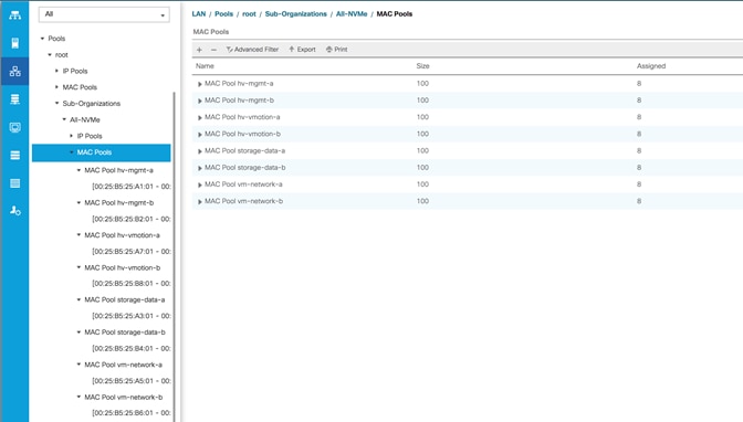
Network Control Policies
Cisco UCS Network Control Policies control various aspects of the behavior of vNICs defined in the Cisco UCS Service Profiles. Settings controlled include enablement of Cisco Discovery Protocol (CDP), MAC address registration, MAC address forging, and the action taken on the vNIC status if the Cisco UCS network uplinks are failed. Two policies are configured by the HyperFlex Installer, HyperFlex-infra is applied to the “infrastructure” vNIC interfaces of the HyperFlex system, and HyperFlex-vm, which is only applied to the vNIC interfaces carrying guest VM traffic. This allows for more flexibility, even though the policies are currently configured with the same settings. Table 17 lists the Network Control Policies configured for HyperFlex, and their default assignment to the vNIC templates created:
Table 17 Network Control Policy
| Name |
CDP |
MAC Register Mode |
Action on Uplink Fail |
MAC Security |
Used by vNIC Template |
| HyperFlex-infra |
Enabled |
Only Native VLAN |
Link-down |
Forged: Allow |
hv-mgmt-a hv-mgmt-b hv-vmotion-a hv-vmotion-b storage-data-a storage-data-b |
| HyperFlex-vm |
Enabled |
Only Native VLAN |
Link-down |
Forged: Allow |
vm-network-a vm-network-b |
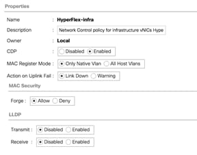
vNIC Templates
Cisco UCS Manager has a feature to configure vNIC templates, which can be used to simplify and speed up configuration efforts. VNIC templates are referenced in service profiles and LAN connectivity policies, versus configuring the same vNICs individually in each service profile, or service profile template. VNIC templates contain all the configuration elements that make up a vNIC, including VLAN assignment, MAC address pool selection, fabric A or B assignment, fabric failover, MTU, QoS policy, Network Control Policy, and more. Templates are created as either initial templates or updating templates. Updating templates retain a link between the parent template and the child object, therefore when changes are made to the template, the changes are propagated to all remaining linked child objects. An additional feature named “vNIC Redundancy” allows vNICs to be configured in pairs, so that the settings of one vNIC template, designated as a primary template, will automatically be applied to a configured secondary template. For all HyperFlex vNIC templates, the “A” side vNIC template is configured as a primary template, and the related “B” side vNIC template is a secondary. In each case, the only configuration difference between the two templates is which fabric they are configured to connect through. The following tables detail the initial settings in each of the vNIC templates created by the HyperFlex installer:
Table 18 vNIC Template hv-mgmt-a
| vNIC Template Name: |
hv-mgmt-a |
|
| Setting |
Value |
|
| Fabric ID |
A |
|
| Fabric Failover |
Disabled |
|
| Target |
Adapter |
|
| Type |
Updating Template |
|
| MTU |
1500 |
|
| MAC Pool |
hv-mgmt-a |
|
| QoS Policy |
silver |
|
| Network Control Policy |
HyperFlex-infra |
|
| VLANs |
<<hx-inband-mgmt>> |
Native: No |
Table 19 vNIC Template hv-mgmt-b
| vNIC Template Name: |
hv-mgmt-b |
|
| Setting |
Value |
|
| Fabric ID |
B |
|
| Fabric Failover |
Disabled |
|
| Target |
Adapter |
|
| Type |
Updating Template |
|
| MTU |
1500 |
|
| MAC Pool |
hv-mgmt-b |
|
| QoS Policy |
silver |
|
| Network Control Policy |
HyperFlex-infra |
|
| VLANs |
<<hx-inband-mgmt>> |
Native: No |
Table 20 vNIC Template hv-vmotion-a
| vNIC Template Name: |
hv-vmotion-a |
|
| Setting |
Value |
|
| Fabric ID |
A |
|
| Fabric Failover |
Disabled |
|
| Target |
Adapter |
|
| Type |
Updating Template |
|
| MTU |
9000 |
|
| MAC Pool |
hv-vmotion-a |
|
| QoS Policy |
bronze |
|
| Network Control Policy |
HyperFlex-infra |
|
| VLANs |
<<hx-vmotion>> |
Native: No |
Table 21 vNIC Template hx-vmotion-b
| vNIC Template Name: |
hv-vmotion-b |
|
| Setting |
Value |
|
| Fabric ID |
B |
|
| Fabric Failover |
Disabled |
|
| Target |
Adapter |
|
| Type |
Updating Template |
|
| MTU |
9000 |
|
| MAC Pool |
hv-vmotion-b |
|
| QoS Policy |
bronze |
|
| Network Control Policy |
HyperFlex-infra |
|
| VLANs |
<<hx-vmotion>> |
Native: No |
Table 22 vNIC Template storage-data-a
| vNIC Template Name: |
storage-data-a |
|
| Setting |
Value |
|
| Fabric ID |
A |
|
| Fabric Failover |
Disabled |
|
| Target |
Adapter |
|
| Type |
Updating Template |
|
| MTU |
9000 |
|
| MAC Pool |
storage-data-a |
|
| QoS Policy |
platinum |
|
| Network Control Policy |
HyperFlex-infra |
|
| VLANs |
<<hx-storage-data>> |
Native: No |
Table 23 vNIC Template storage-data-b
| vNIC Template Name: |
storage-data-b |
|
| Setting |
Value |
|
| Fabric ID |
B |
|
| Fabric Failover |
Disabled |
|
| Target |
Adapter |
|
| Type |
Updating Template |
|
| MTU |
9000 |
|
| MAC Pool |
storage-data-b |
|
| QoS Policy |
platinum |
|
| Network Control Policy |
HyperFlex-infra |
|
| VLANs |
<<hx-storage-data>> |
Native: No |
Table 24 vNIC Template vm-network-a
| vNIC Template Name: |
vm-network-a |
|
| Setting |
Value |
|
| Fabric ID |
A |
|
| Fabric Failover |
Disabled |
|
| Target |
Adapter |
|
| Type |
Updating Template |
|
| MTU |
1500 |
|
| MAC Pool |
vm-network-a |
|
| QoS Policy |
gold |
|
| Network Control Policy |
HyperFlex-vm |
|
| VLANs |
<<vm-network>> |
Native: no |
Table 25 vNIC Template vm-network-b
| vNIC Template Name: |
vm-network-b |
|
| Setting |
Value |
|
| Fabric ID |
B |
|
| Fabric Failover |
Disabled |
|
| Target |
Adapter |
|
| Type |
Updating Template |
|
| MTU |
1500 |
|
| MAC Pool |
vm-network-b |
|
| QoS Policy |
gold |
|
| Network Control Policy |
HyperFlex-vm |
|
| VLANs |
<<vm-network>> |
Native: no |
LAN Connectivity Policies
Cisco UCS Manager has a feature for LAN Connectivity Policies, which aggregates all of the vNICs or vNIC templates desired for a service profile configuration into a single policy definition. This simplifies configuration efforts by defining a collection of vNICs or vNIC templates once, then using that policy in the service profiles or service profile templates. The HyperFlex installer configures a LAN Connectivity Policy named HyperFlex, which contains all of the vNIC templates defined in the previous section, along with an Adapter Policy named HyperFlex, also configured by the HyperFlex installer. Table 26 lists the LAN Connectivity Policy configured for HyperFlex:
Table 26 LAN Connectivity Policy
| Policy Name |
Use vNIC Template |
vNIC Name |
vNIC Template Used |
Adapter Policy |
| HyperFlex |
Yes |
hv-mgmt-a |
hv-mgmt-a |
HyperFlex |
| hv-mgmt-b |
hv-mgmt-b |
|||
| hv-vmotion-a |
hv-vmotion-a |
|||
| hv-vmotion-b |
hv-vmotion-b |
|||
| storage-data-a |
storage-data-a |
|||
| storage-data-b |
storage-data-b |
|||
| vm-network-a |
vm-network-a |
|||
| vm-network-b |
vm-network-b |
Cisco UCS Servers Policies
Adapter Policies
Cisco UCS Adapter Policies are used to configure various settings of the Converged Network Adapter (CNA) installed in the Cisco UCS blade or rack-mount servers. Various advanced hardware features can be enabled or disabled depending on the software or operating system being used. The following figures detail the Adapter Policy named “HyperFlex”, configured for HyperFlex:
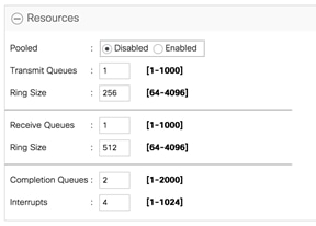
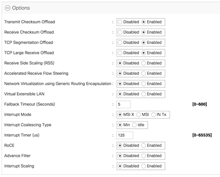
BIOS Policies
Cisco UCS Manager utilizes policies applied via the service profiles, in order to modify settings in the BIOS of the associated server. Cisco HX-Series M5 generation servers no longer use predefined BIOS setting defaults derived from Cisco UCS Manager, instead the servers have default BIOS tokens set from the factory. The current default token settings can be viewed at the following website: https://www.cisco.com/c/en/us/td/docs/unified_computing/ucs/ucs-manager/Reference-Docs/Server-BIOS-Tokens/4-0/b_UCS_BIOS_Tokens_Guide_4_0.html
A BIOS policy named “HyperFlex-m5” is created by the HyperFlex installer to modify the settings of the M5 generation servers. The settings modified are as follows:
· System altitude is set to “Auto”
· CPU performance is set to “HPC”
· CPU direct cache access is set to “Enabled”
· Intel Virtualization Technology is set to “Enabled”
· IMC Interleave is set to “Auto”
· Sub NUMA clustering is set to “Disabled”
· Processor C states are all set to “Disabled”
· Power Technology is set to “Performance”
· Energy Performance is set to “Performance”
· LLC Prefetch is set to “Disabled”
· XPT Prefetch is set to “Disabled”
· Intel VTD coherency support is set to “Disabled”
· Intel VT for Directed IO is set to “Enabled”
· Intel VTD interrupt Remapping is set to “Enabled”
· Serial Port A is enabled
· PCI Memory mapped IO above 4GB is set to “Enabled”
· Console Redirection is set to “Serial Port A”
· Out of band management is set to “Enabled”
A third BIOS policy named “HyperFlex-nvme” is also created with the same settings as found in the “HyperFlex-m5” policy above.
Boot Policies
Cisco UCS Boot Policies define the boot devices used by blade and rack-mount servers, and the order that they are attempted to boot from. Cisco HX-Series M5 generation rack-mount servers have their VMware ESXi hypervisors installed to an internal M.2 SSD boot drive, therefore they require a unique boot policy defining that the servers should boot from that location. The HyperFlex installer configures a boot policy named “HyperFlex-m5” specifying boot from the M.2 SSDs, referred to as “Embedded Disk”, which is used by the HyperFlex M5 converged nodes, and should not be modified. The HyperFlex installer configures a boot policy named “hx-compute-m5”, which can be modified as needed for the boot method used by the M5 generation compute-only nodes. The following figure details the HyperFlex Boot Policy:
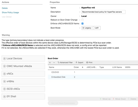
Host Firmware Packages
Cisco UCS Host Firmware Packages represent one of the most powerful features of the Cisco UCS platform; the ability to control the firmware revision of all the managed blades and rack-mount servers via a policy specified in the service profile. Host Firmware Packages are defined and referenced in the service profiles. Once a service profile is associated to a server, the firmware of all the components defined in the Host Firmware Package are automatically upgraded or downgraded to match the package. The HyperFlex installer creates a Host Firmware Package named “HyperFlex-m5” which uses the simple package definition method, applying firmware revisions to all components that matches a specific Cisco UCS firmware bundle, versus defining the firmware revisions part by part. The following figure details the Host Firmware Package configured by the HyperFlex installer:
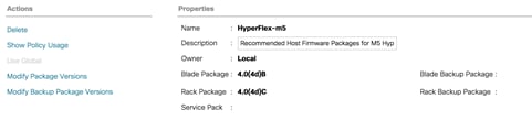
Local Disk Configuration Policies
Cisco UCS Local Disk Configuration Policies are used to define the configuration of disks installed locally within each blade or rack-mount server, most often to configure Redundant Array of Independent/Inexpensive Disks (RAID levels) when multiple disks are present for data protection. Since HX-Series converged nodes providing storage resources do not require RAID, the HyperFlex installer creates four Local Disk Configuration Policies which allows any local disk configuration. The policy named “HyperFlex-m5” is used by the service profile template named “hx-nodes-m5”, which is for the HyperFlex M5 generation converged servers, and should not be modified.
Meanwhile, the policies named “hx-compute” and “hx-compute-m5” are used by the service profile templates named “compute-nodes” and “compute-nodes-m5”, which are used by compute-only nodes. The two compute-only node policies can be modified as needed to suit the local disk configuration that will be used in compute-only nodes.
The following figure details the Local Disk Configuration Policy configured by the HyperFlex installer:
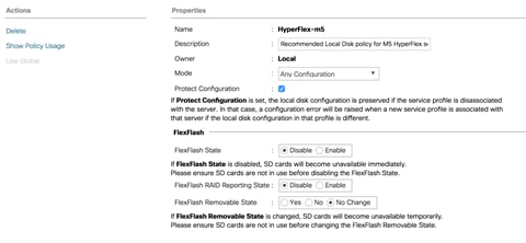
![]() Note: Additional policies are created for use by Cisco UCS M4 generation HX-series servers, including additional BIOS policies, Boot Policies, Host Firmware Packages and Local Disk Configuration Policies. Because this document no longer covers the installation and configuration of M4 generation hardware, the settings in these policies are not outlined here. Please refer to previous editions of this Cisco Validated Design document as a reference for these policies targeted at M4 generation hardware.
Note: Additional policies are created for use by Cisco UCS M4 generation HX-series servers, including additional BIOS policies, Boot Policies, Host Firmware Packages and Local Disk Configuration Policies. Because this document no longer covers the installation and configuration of M4 generation hardware, the settings in these policies are not outlined here. Please refer to previous editions of this Cisco Validated Design document as a reference for these policies targeted at M4 generation hardware.
Maintenance Policies
Cisco UCS Maintenance Policies define the behavior of the attached blades and rack-mount servers when changes are made to the associated service profiles. The default Cisco UCS Maintenance Policy setting is “Immediate” meaning that any change to a service profile that requires a reboot of the physical server will result in an immediate reboot of that server. The Cisco best practice is to use a Maintenance Policy set to “user-ack”, which requires a secondary acknowledgement by a user with the appropriate rights within Cisco UCS Manager, before the server is rebooted to apply the changes. The HyperFlex installer creates a Maintenance Policy named “HyperFlex” with the setting changed to “user-ack”. In addition, the On Next Boot setting is enabled, which will automatically apply changes the next time the server is rebooted, without any secondary acknowledgement. Figure 33 details the Maintenance Policy configured by the HyperFlex installer:
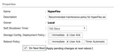
Power Control Policies
Cisco UCS Power Control Policies allow administrators to set priority values for power application to servers in environments where power supply may be limited, during times when the servers demand more power than is available. The HyperFlex installer creates a Power Control Policy named “HyperFlex” with all power capping disabled, and fans allowed to run at full speed when necessary. Figure 34 details the Power Control Policy configured by the HyperFlex installer:
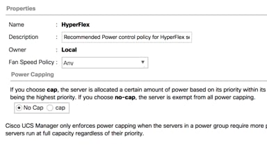
Scrub Policies
Cisco UCS Scrub Policies are used to scrub, or erase data from local disks, BIOS settings and FlexFlash SD cards. If the policy settings are enabled, the information is wiped when the service profile using the policy is disassociated from the server. The HyperFlex installer creates a Scrub Policy named “HyperFlex” which has all settings disabled, therefore all data on local disks, SD cards and BIOS settings will be preserved if a service profile is disassociated. Figure 35 details the Scrub Policy configured by the HyperFlex installer:
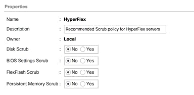
Serial over LAN Policies
Cisco UCS Serial over LAN (SoL) Policies enable console output which is sent to the serial port of the server, to be accessible via the LAN. For many Linux based operating systems, such as VMware ESXi, the local serial port can be configured as a local console, where users can watch the system boot, and communicate with the system command prompt interactively. Since many blade servers do not have physical serial ports, and often administrators are working remotely, the ability to send and receive that traffic via the LAN is very helpful. Connections to a SoL session can be initiated from Cisco UCS Manager. The HyperFlex installer creates a SoL policy named “HyperFlex” to enable SoL sessions and uses this feature to configure the ESXi hosts’ management networking configuration. Figure 36 details the SoL Policy configured by the HyperFlex installer:
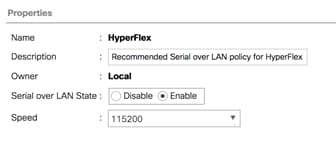
vMedia Policies
Cisco UCS Virtual Media (vMedia) Policies automate the connection of virtual media files to the remote KVM session of the Cisco UCS blades and rack-mount servers. Using a vMedia policy can speed up installation time by automatically attaching an installation ISO file to the server, without having to manually launch the remote KVM console and connect them one-by-one. The HyperFlex installer creates a vMedia Policy named “HyperFlex” for future use, with no media locations defined.
Cisco UCS Service Profile Templates
Cisco UCS Manager has a feature to configure service profile templates, which can be used to simplify and speed up configuration efforts when the same configuration needs to be applied to multiple servers. Service profile templates are used to spawn multiple service profile copies to associate with a group of servers, versus configuring the same service profile manually each time it is needed. Service profile templates contain all the configuration elements that make up a service profile, including vNICs, vHBAs, local disk configurations, boot policies, host firmware packages, BIOS policies and more. Templates are created as either initial templates or updating templates. Updating templates retain a link between the parent template and the child object, therefore when changes are made to the template, the changes are propagated to all remaining linked child objects. The HyperFlex installer creates service profile templates named “hx-nodes-m5” and “compute-nodes-m5”, each with nearly the same configuration, except for the BIOS, firmware, local disk configuration and boot policies. This simplifies future efforts if the configuration of the compute only nodes needs to differ from the configuration of the HyperFlex converged storage nodes. The following tables detail the service profile templates configured by the HyperFlex installer:
Table 27 Cisco UCS Service Profile Template Settings and Values
| Service Profile Template Name: |
hx-nodes-m5 |
| Setting |
Value |
| UUID Pool |
Hardware Default |
| Associated Server Pool |
None |
| Maintenance Policy |
HyperFlex |
| Management IP Address Policy |
hx-ext-mgmt |
| Local Disk Configuration Policy |
HyperFlex-m5 |
| LAN Connectivity Policy |
HyperFlex |
| Boot Policy |
HyperFlex-m5 |
| BIOS Policy |
HyperFlex-m5 |
| Firmware Policy |
HyperFlex-m5 |
| Power Control Policy |
HyperFlex |
| Scrub Policy |
HyperFlex |
| Serial over LAN Policy |
HyperFlex |
| vMedia Policy |
Not defined |
| Service Profile Template Name: |
compute-nodes-m5 |
| Setting |
Value |
| UUID Pool |
Hardware Default |
| Associated Server Pool |
None |
| Maintenance Policy |
HyperFlex |
| Management IP Address Policy |
hx-ext-mgmt |
| Local Disk Configuration Policy |
hx-compute-m5 |
| LAN Connectivity Policy |
HyperFlex |
| Boot Policy |
hx-compute-m5 |
| BIOS Policy |
HyperFlex-m5 |
| Firmware Policy |
HyperFlex-m5 |
| Power Control Policy |
HyperFlex |
| Scrub Policy |
HyperFlex |
| Serial over LAN Policy |
HyperFlex |
| vMedia Policy |
Not defined |
![]() Note: Additional templates are created for use by Cisco UCS M4 generation HX-series servers. Because this document no longer covers the installation and configuration of M4 generation hardware, the settings in these templates are not outlined here. Please refer to previous editions of this Cisco Validated Design document as a reference for these templates targeted at M4 generation hardware.
Note: Additional templates are created for use by Cisco UCS M4 generation HX-series servers. Because this document no longer covers the installation and configuration of M4 generation hardware, the settings in these templates are not outlined here. Please refer to previous editions of this Cisco Validated Design document as a reference for these templates targeted at M4 generation hardware.
vNIC/vHBA Placement
In order to control the order of detection of the vNICs and vHBAs defined in service profiles, Cisco UCS allows for the definition of the placement of the vNICs and vHBAs across the cards in a blade or rack-mount server, and the order they are seen. In certain hardware configurations, the physical mapping of the installed cards and port extenders to their logical order is not linear, therefore each card is referred to as a virtual connection, or vCon. Because of this, the placement and detection order of the defined vNICs and vHBAs does not refer to physical cards, but instead refers to a vCon. HX-series servers are most often configured with a single Cisco UCS VIC mLOM card. An optional configuration does allow for two VIC cards to be used for an extra layer of physical redundancy. To accommodate this option, the vCon placement policy alternates between vCon 1 and vCon 2. If two cards were present, then the 8 vNICs would be evenly distributed across both cards. With a single Cisco VIC card installed, the only available placement is on vCon 1. In this scenario, all the vNICs defined in the service profile templates for HX-series servers will be placed on vCon 1, despite some of them being set to be placed on vCon 2. In either case, the resulting detection order is the same, giving a consistent enumeration of the interfaces as seen by the VMware ESXi hypervisor.
Through the combination of the vNIC templates created (vNIC Templates), the LAN Connectivity Policy (LAN Connectivity Policies), and the vNIC placement, every VMware ESXi server will detect the same network interfaces in a known and identical order, and they will always be connected to the same VLANs via the same network fabrics. The following table outlines the vNICs, their placement, their order, the fabric they are connected to, their default VLAN, and how they are enumerated by the ESXi hypervisor:
| vNIC |
Placement |
Order |
Fabric |
VLAN |
ESXi interface enumeration |
| hv-mgmt-a |
1 |
1 |
A |
<<hx-inband-mgmt>> |
vmnic0 |
| hv-mgmt-b |
2 |
5 |
B |
<<hx-inband-mgmt>> |
vmnic4 |
| storage-data-a |
1 |
2 |
A |
<<hx-storage-data>> |
vmnic1 |
| storage-data-b |
2 |
6 |
B |
<<hx-storage-data>> |
vmnic5 |
| vm-network-a |
1 |
3 |
A |
<<vm-network>> |
vmnic2 |
| vm-network-b |
2 |
7 |
B |
<<vm-network>> |
vmnic6 |
| hv-vmotion-a |
1 |
4 |
A |
<<hx-vmotion>> |
vmnic3 |
| hv-vmotion-b |
2 |
8 |
B |
<<hx-vmotion>> |
vmnic7 |
![]() Note: ESXi VMDirectPath relies on a fixed PCI address for the passthrough devices. If the configuration is changed by adding or removing vNICs or vHBAs, then the order of the devices seen in the PCI tree will change. The ESXi hosts will subsequently need to reboot one additional time in order to repair the configuration, which they will do automatically.
Note: ESXi VMDirectPath relies on a fixed PCI address for the passthrough devices. If the configuration is changed by adding or removing vNICs or vHBAs, then the order of the devices seen in the PCI tree will change. The ESXi hosts will subsequently need to reboot one additional time in order to repair the configuration, which they will do automatically.
ESXi Host Design
The following sections detail the design of the elements within the VMware ESXi hypervisors, system requirements, virtual networking and the configuration of ESXi for the Cisco HyperFlex HX Distributed Data Platform.
Virtual Networking Design
The Cisco HyperFlex system has a pre-defined virtual network design at the ESXi hypervisor level. Four different virtual switches are created by the HyperFlex installer, each using two uplinks, which are each serviced by a vNIC defined in the Cisco UCS service profile. The vSwitches created are:
· vswitch-hx-inband-mgmt: This is the default vSwitch0 which is renamed by the ESXi kickstart file as part of the automated installation. The default VMkernel port, vmk0, is configured in the standard Management Network port group. The switch has two uplinks, active on fabric A and standby on fabric B, without jumbo frames. A second port group is created for the Storage Platform Controller VMs to connect to with their individual management interfaces. A third port group is created for cluster to cluster VM snapshot replication traffic. The VLANs are not Native VLANs as assigned to the vNIC templates, and therefore they are defined in ESXi/vSphere.
· vswitch-hx-storage-data: This vSwitch is created as part of the automated installation. A VMkernel port, vmk1, is configured in the Storage Hypervisor Data Network port group, which is the interface used for connectivity to the HX Datastores via NFS. The switch has two uplinks, active on fabric B and standby on fabric A, with jumbo frames highly recommended. A second port group is created for the Storage Platform Controller VMs to connect to with their individual storage interfaces. The VLAN is not a Native VLAN as assigned to the vNIC templates, and therefore they are defined in ESXi/vSphere.
· vswitch-hx-vm-network: This vSwitch is created as part of the automated installation. The switch has two uplinks, active on both fabrics A and B, and without jumbo frames. The VLANs are not Native VLANs as assigned to the vNIC templates, and therefore they are defined in ESXi/vSphere.
· vmotion: This vSwitch is created as part of the automated installation. The switch has two uplinks, active on fabric A and standby on fabric B, with jumbo frames highly recommended. The IP addresses of the VMkernel ports (vmk2) are configured during the post_install script execution. The VLAN is not a Native VLAN as assigned to the vNIC templates, and therefore they are defined in ESXi/vSphere.
The following table and figures provide more details about the ESXi virtual networking design as built by the HyperFlex installer by default:
| Virtual Switch |
Port Groups |
Active vmnic(s) |
Passive vmnic(s) |
VLAN IDs |
Jumbo |
| vswitch-hx-inband-mgmt |
Management Network Storage Controller Management Network |
vmnic0 |
vmnic4 |
<<hx-inband-mgmt>> |
no |
| Storage Controller Replication Network |
vmnic0 |
vmnic4 |
<<hx-inband-repl>> |
no |
|
| vswitch-hx-storage-data |
Storage Controller Data Network Storage Hypervisor Data Network |
vmnic5 |
vmnic1 |
<<hx-storage-data>> |
yes |
| vswitch-hx-vm-network |
vm-network-<<VLAN ID>> |
vmnic2 vmnic6 |
<<vm-network>> |
no |
|
| vmotion |
vmotion-<<VLAN ID>> |
vmnic3 |
vmnic7 |
<<hx-vmotion>> |
yes |

VMDirectPath I/O Passthrough
VMDirectPath I/O allows a guest VM to directly access PCI and PCIe devices in an ESXi host as though they were physical devices belonging to the VM itself, also referred to as PCI passthrough. With the appropriate driver for the hardware device, the guest VM sends all I/O requests directly to the physical device, bypassing the hypervisor. In the Cisco HyperFlex system, the Storage Platform Controller VMs use this feature to gain full control of the Cisco 12Gbps SAS HBA cards in the Cisco HX-series rack-mount servers. This gives the controller VMs direct hardware level access to the physical disks installed in the servers, which they consume to construct the Cisco HX Distributed Filesystem. In all-flash model servers equipped with an NVMe caching SSD, VMDirectPath is also configured for the caching disk, since it is not connected to an HBA card. In all-NVMe model servers there is no SAS HBA at all, and all of the NVMe caching and capacity SSDs are configured via VMDirectPath I/O so that the controller VMs have direct access to all of the disks. Other disks, connected to different controllers, such as the M.2 boot SSDs, remain under the control of the ESXi hypervisor. Lastly, when the Cisco HyperFlex Acceleration Engine card is installed, VMDirectPath I/O is also configured to give the controller VMs direct access to the cards as well. The configuration of the VMDirectPath I/O feature is done by the Cisco HyperFlex installer and requires no manual steps.
Storage Platform Controller Virtual Machines
A key component of the Cisco HyperFlex system is the Storage Platform Controller Virtual Machine running on each of the nodes in the HyperFlex cluster. The controller VMs cooperate to form and coordinate the Cisco HX Distributed Filesystem, and service all the guest VM IO requests. The storage controller VM runs custom software and services that manage and maintain the Cisco HX Distributed Filesystem. The services and processes that run within the controller VMs are not exposed directly to the ESXi hosts, although the controller VMs are configured to automatically start and stop with the ESXi hosts and protected from accidental deletion. Management and visibility into the function of the controller VMs, and the Cisco HX Distributed Filesystem is done via the HyperFlex Connect HTML management webpage, or a plugin installed to the vCenter server or appliance managing the vSphere cluster. The plugin communicates directly with the controller VMs to display the information requested, or make the configuration changes directed, all while operating within the same web-based interface of the vSphere Web Client. The deployment of the controller VMs and vCenter plugins are all done by the Cisco HyperFlex installer and requires no manual steps.
Controller Virtual Machine Locations
The physical storage location of the controller VMs differs among the Cisco HX-Series rack servers, due to differences with the physical disk location and connections on those server models. The storage controller VM is operationally no different from any other typical virtual machines in an ESXi environment. The VM must have a virtual disk with the bootable root filesystem available in a location separate from the SAS HBA that the VM is controlling via VMDirectPath I/O. The configuration details of the models are as follows:
· HX220c M5, HXAF220c M5, HX240c M5L, HX240c M5 and HXAF240c M5: The server boots the ESXi hypervisor from the internal M.2 form factor SSD. The M.2 SSD is partitioned by the ESXi installer, and the remaining 216 GB of space is used as a VMFS datastore. The controller VM’s root filesystem is stored on a 2.5 GB virtual disk, /dev/sda, which is placed on this VMFS datastore. The controller VM has full control of all the front and rear facing SAS based hot-swappable disks via PCI passthrough control of the SAS HBA. The controller VM operating system sees the 240 GB SSD, also commonly called the “housekeeping” disk as /dev/sdb, and places HyperFlex binaries and logs on this disk. The remaining disks seen by the controller VM OS are used by the HX Distributed filesystem for caching and capacity layers.
· HX220c M5N: The server boots the ESXi hypervisor from the internal M.2 form factor SSD. The M.2 SSD is partitioned by the ESXi installer, and the remaining 216 GB of space is used as a VMFS datastore. The controller VM’s root filesystem is stored on a 2.5 GB virtual disk, /dev/sda, which is placed on this VMFS datastore. The controller VM has full control of all the front facing NVMe based hot-swappable SSDs directly connected through the PCIe bus via PCI Passthrough. The controller VM operating system sees the 240 GB SSD, also commonly called the “housekeeping” disk as /dev/sdb, and places HyperFlex binaries and logs on this disk. The remaining disks seen by the controller VM OS are used by the HX Distributed filesystem for caching and capacity layers.
The following figures detail the Storage Platform Controller VM placement on the ESXi hypervisor hosts:
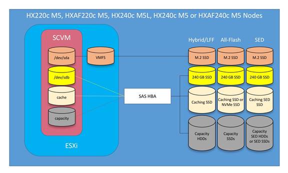
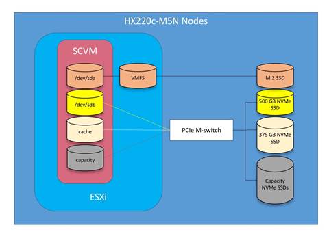
![]() Note: HyperFlex compute-only nodes install a lightweight controller VM in the VMFS datastore automatically created during the installation of ESXi. This VM performs no storage functions and is only used for node coordination.
Note: HyperFlex compute-only nodes install a lightweight controller VM in the VMFS datastore automatically created during the installation of ESXi. This VM performs no storage functions and is only used for node coordination.
HyperFlex Datastores
A new HyperFlex cluster has no default datastores configured for virtual machine storage, therefore the datastores must be created using the vCenter Web Client plugin or the HyperFlex Connect GUI. It is important to recognize that all HyperFlex datastores are thinly provisioned, meaning that their configured size can far exceed the actual space available in the HyperFlex cluster. Alerts will be raised by the HyperFlex system in HyperFlex Connect or the vCenter plugin when actual space consumption results in low amounts of free space, and alerts will be sent via auto support email alerts. Overall space consumption in the HyperFlex clustered filesystem is optimized by the default deduplication and compression features.
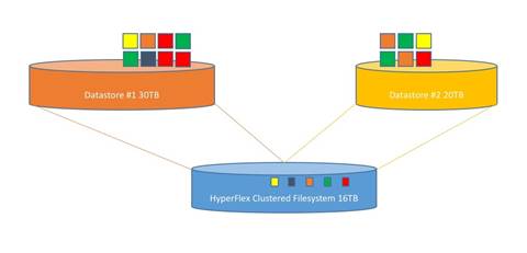
CPU Resource Reservations
Since the storage controller VMs provide critical functionality of the Cisco HX Distributed Data Platform, the HyperFlex installer will configure CPU resource reservations for the controller VMs. This reservation guarantees that the controller VMs will have CPU resources at a minimum level, in situations where the physical CPU resources of the ESXi hypervisor host are being heavily consumed by the guest VMs. This is a soft guarantee, meaning in most situations the SCVMs are not using all of the CPU resources reserved, therefore allowing the guest VMs to use them. The following table details the CPU resource reservation of the storage controller VMs:
Table 30 Controller VM CPU Reservations
| Server Models |
Number of vCPU |
Shares |
Reservation |
Limit |
| All hybrid and all-flash models |
8 |
Low |
10800 MHz |
unlimited |
| All-NVMe models |
12 |
Low |
10800 MHz |
unlimited |
Memory Resource Reservations
Since the storage controller VMs provide critical functionality of the Cisco HX Distributed Data Platform, the HyperFlex installer will configure memory resource reservations for the controller VMs. This reservation guarantees that the controller VMs will have memory resources at a minimum level, in situations where the physical memory resources of the ESXi hypervisor host are being heavily consumed by the guest VMs. The following table details the memory resource reservation of the storage controller VMs:
Table 31 Controller VM Memory Reservations
| Server Models |
Amount of Guest Memory |
Reserve All Guest Memory |
| HX220c-M5SX HXAF220c-M5SX |
48 GB |
Yes |
| HXAF220c-M5N HX240c-M5SX HXAF240c-M5SX |
72 GB |
Yes |
| HX240c-M5L |
78 GB |
Yes |
Cisco HyperFlex systems are ordered with a factory pre-installation process having been done prior to the hardware delivery. This factory integration work will deliver the HyperFlex servers with the proper firmware revisions pre-set, a copy of the VMware ESXi hypervisor software pre-installed, and some components of the Cisco HyperFlex software already installed. Once on site, the final steps to be performed are reduced and simplified due to the previous factory work. For the purpose of this document, the setup process is described presuming that this factory pre-installation work was done, thereby leveraging the tools and processes developed by Cisco to simplify the process and dramatically reduce the deployment time. The following sections will guide you through the prerequisites and manual steps needed prior to using the HyperFlex installer via Cisco Intersight, how to configure the HyperFlex profiles in Cisco Intersight and perform the installation, then finally how to perform the remaining post-installation tasks.
Prerequisites
Prior to beginning the installation activities, it is important to gather the following information:
IP Addressing
IP addresses for the Cisco HyperFlex system need to be allocated from the appropriate subnets and VLANs to be used. IP addresses that are used by the system fall into the following groups:
· Cisco UCS Manager: These addresses are used and assigned by Cisco UCS manager. Three IP addresses are used by Cisco UCS Manager; one address is assigned to each Cisco UCS Fabric Interconnect, and the third IP address is a roaming address for management of the Cisco UCS cluster. In addition, at least one IP address per Cisco UCS blade or HX-series rack-mount server is required for the hx-ext-mgmt IP address pool, which are assigned to the CIMC interface of the physical servers. Since these management addresses are assigned from a pool, they need to be provided in a contiguous block of addresses. These addresses must all be in the same subnet.
· HyperFlex and ESXi Management: These addresses are used to manage the ESXi hypervisor hosts, and the HyperFlex Storage Platform Controller VMs. Two IP addresses per node in the HyperFlex cluster are required from the same subnet, and a single additional IP address is needed as the roaming HyperFlex cluster management interface. These addresses can be assigned from the same subnet at the Cisco UCS Manager addresses, or they may be separate.
· HyperFlex Replication: These addresses are used by the HyperFlex Storage Platform Controller VMs for clusters that are configured to replicate VMs to one another. One IP address per HX node is required, plus one additional IP address as a roaming clustered replication interface. These addresses are assigned to a pool as part of a post-installation activity described later in this document and are not needed to complete the initial installation of a HyperFlex cluster. These addresses can be from the same subnet as the HyperFlex and ESXi management addresses, but it is recommended that the VLAN ID and subnet be unique.
· HyperFlex Storage: These addresses are used by the HyperFlex Storage Platform Controller VMs, and as VMkernel interfaces on the ESXi hypervisor hosts, for sending and receiving data to/from the HX Distributed Data Platform Filesystem. These addresses are automatically provisioned to the nodes from the link-local IPv4 subnet of 169.254.0.0/16 and do not need to be manually assigned prior to installation. Two IP addresses per node in the HyperFlex cluster are assigned from the subnet, and a single additional IP address is assigned as the roaming HyperFlex cluster storage interface. The third octet of the IP addresses is derived from the MAC address pool prefix by converting that value to a decimal number, thereby creating a unique subnet for each cluster, as the subnet mask set on the hosts for these VMkernel ports is actually 255.255.255.0. The value for the fourth octet is sequentially set, starting with .1 for the overall cluster, then proceeding to .2 for the vmk1(Hypervisor) port of the first server, then .3 for the Storage Controller VM of the first server. The second server would be assigned .4 for its vmk1 port, and .5 for its Storage Controller VM, and this pattern continues for each subsequent server. It is recommended to provision a VLAN ID that is not used in the network for other purposes. Finally, if the Cisco UCS domain is going to contain multiple HyperFlex clusters, it is recommended to use a different VLAN ID for the HyperFlex storage traffic for each cluster, as this is a safer method, guaranteeing that storage traffic from multiple clusters cannot intermix.
· VMotion: These IP addresses are used by the ESXi hypervisor hosts as VMkernel interfaces to enable vMotion capabilities. One or more IP addresses per node in the HyperFlex cluster are required from the same subnet. Multiple addresses and VMkernel interfaces can be used if you wish to enable multi-NIC vMotion, although this configuration would require additional manual steps.
The following tables will assist with gathering the required IP addresses for the installation of an 8-node standard HyperFlex cluster, or a 4+4 extended cluster, by listing the addresses required, plus an example IP configuration:
![]() Note: Table cells shaded in black do not require an IP address.
Note: Table cells shaded in black do not require an IP address.
Table 32 HyperFlex Standard Cluster IP Addressing
| UCS Management |
HyperFlex and ESXi Management |
HyperFlex Storage |
VMotion |
||||
| VLAN ID: |
|
|
|
|
|
||
| Subnet: |
|
|
|
|
|
||
| Subnet Mask: |
|
|
|
|
|
||
| Gateway: |
|
|
|
|
|
||
| Device |
UCS Management Addresses |
ESXi Management Interfaces |
Storage Controller VM Management Interfaces |
Storage Controller VM Replication Interfaces |
ESXi Hypervisor Storage VMkernel Interfaces |
Storage Controller VM Storage Interfaces |
VMotion VMkernel Interfaces |
| Fabric Interconnect A |
|
|
|
|
|
|
|
| Fabric Interconnect B |
|
|
|
|
|
|
|
| UCS Manager |
|
|
|
|
|
|
|
| HyperFlex Cluster |
|
|
|
|
|
|
|
| HyperFlex Node #1 |
|
|
|
|
|
|
|
| HyperFlex Node #2 |
|
|
|
|
|
|
|
| HyperFlex Node #3 |
|
|
|
|
|
|
|
| HyperFlex Node #4 |
|
|
|
|
|
|
|
| HyperFlex Node #5 |
|
|
|
|
|
|
|
| HyperFlex Node #6 |
|
|
|
|
|
|
|
| HyperFlex Node #7 |
|
|
|
|
|
|
|
| HyperFlex Node #8 |
|
|
|
|
|
|
|
![]() Note: If the on-premises HyperFlex installer VM is used instead of Cisco Intersight for the installation, then IP addresses for the HyperFlex storage components must be manually assigned and provided during the installation process.
Note: If the on-premises HyperFlex installer VM is used instead of Cisco Intersight for the installation, then IP addresses for the HyperFlex storage components must be manually assigned and provided during the installation process.
HyperFlex extended clusters are also addressed similarly to a standard cluster, they require additional IP addresses for Cisco UCS management and ESXi management, as shown below:
Table 33 HyperFlex Standard Cluster Example IP Addressing
| Address Group: |
UCS Management |
HyperFlex and ESXi Management |
HyperFlex Storage |
VMotion |
|||
| VLAN ID: |
132 |
30 |
133 |
101 |
35 |
||
| Subnet: |
10.29.132.0 |
10.29.132.0 |
192.168.101.0 |
169.254.0.0 |
192.168.201.0 |
||
| Subnet Mask: |
255.255.255.0 |
255.255.255.0 |
255.255.255.0 |
255.255.255.0 |
255.255.255.0 |
||
| Gateway: |
10.29.132.1 |
10.29.132.1 |
192.168.101.1 |
|
|
||
| Device |
UCS Management Addresses |
ESXi Management Interfaces |
Storage Controller VM Management Interfaces |
Storage Controller VM Replication Interfaces |
ESXi Hypervisor Storage VMkernel Interfaces |
Storage Controller VM Storage Interfaces |
VMotion VMkernel Interfaces |
| Fabric Interconnect A |
10.29.132.104 |
|
|
|
|
|
|
| Fabric Interconnect B |
10.29.132.105 |
|
|
|
|
|
|
| UCS Manager |
10.29.132.106 |
|
|
|
|
|
|
| HyperFlex Cluster |
|
|
10.29.132.182 |
192.168.101.40 |
|
auto |
|
| HyperFlex Node #1 |
10.29.132.166 |
10.29.132.174 |
10.29.132.183 |
192.168.101.41 |
auto |
auto |
192.168.201.61 |
| HyperFlex Node #2 |
10.29.132.167 |
10.29.132.175 |
10.29.132.184 |
192.168.101.42 |
auto |
auto |
192.168.201.62 |
| HyperFlex Node #3 |
10.29.132.168 |
10.29.132.176 |
10.29.132.185 |
192.168.101.43 |
auto |
auto |
192.168.201.63 |
| HyperFlex Node #4 |
10.29.132.169 |
10.29.132.177 |
10.29.132.186 |
192.168.101.44 |
auto |
auto |
192.168.201.64 |
| HyperFlex Node #5 |
10.29.132.170 |
10.29.132.178 |
10.29.132.187 |
192.168.101.45 |
auto |
auto |
192.168.201.65 |
| HyperFlex Node #6 |
10.29.132.171 |
10.29.132.179 |
10.29.132.188 |
192.168.101.46 |
auto |
auto |
192.168.201.66 |
| HyperFlex Node #7 |
10.29.132.172 |
10.29.132.180 |
10.29.132.189 |
192.168.101.47 |
auto |
auto |
192.168.201.67 |
| HyperFlex Node #8 |
10.29.132.173 |
10.29.132.181 |
10.29.132.190 |
192.168.101.48 |
auto |
auto |
192.168.201.68 |
![]() Note: IP addresses for Cisco UCS Management, plus HyperFlex and ESXi Management can come from the same subnet, or can be separate subnets, as long as the HyperFlex installer can reach them both.
Note: IP addresses for Cisco UCS Management, plus HyperFlex and ESXi Management can come from the same subnet, or can be separate subnets, as long as the HyperFlex installer can reach them both.
DHCP versus Static IP
By default, the HX installation will assign a static IP address to the management interface of the ESXi servers. Using Dynamic Host Configuration Protocol (DHCP) for automatic IP address assignment in not recommended.
DNS
DNS servers are highly recommended to be configured for querying Fully Qualified Domain Names (FQDN) in the HyperFlex and ESXi Management group. DNS records need to be created prior to beginning the installation. At a minimum, it is highly recommended to create A records and reverse PTR records for the ESXi hypervisor hosts’ management interfaces. Additional DNS A records can be created for the Storage Controller Management interfaces, ESXi Hypervisor Storage interfaces, and the Storage Controller Storage interfaces if desired.
The following tables will assist with gathering the required DNS information for the installation, by listing the information required, and an example configuration:
Table 34 DNS Server Information
| Item |
Value |
| DNS Server #1 |
|
| DNS Server #2 |
|
| DNS Domain |
|
| vCenter Server Name |
|
| SMTP Server Name |
|
| UCS Domain Name |
|
| HX Server #1 Name |
|
| HX Server #2 Name |
|
| HX Server #3 Name |
|
| HX Server #4 Name |
|
| HX Server #5 Name |
|
| HX Server #6 Name |
|
| HX Server #7 Name |
|
| HX Server #8 Name |
|
Table 35 DNS Server Example Information
| Item |
Value |
| DNS Server #1 |
10.29.132.110 |
| DNS Server #2 |
|
| DNS Domain |
hxdom.local |
| vCenter Server Name |
vcenter.hxdom.local |
| SMTP Server Name |
outbound.cisco.com |
| UCS Domain Name |
HX-FI |
| HX Server #1 Name |
hxaf220m5n-01.hxdom.local |
| HX Server #2 Name |
hxaf220m5n-02.hxdom.local |
| HX Server #3 Name |
hxaf220m5n-03.hxdom.local |
| HX Server #4 Name |
hxaf220m5n-04.hxdom.local |
| HX Server #5 Name |
hxaf220m5n-05.hxdom.local |
| HX Server #6 Name |
hxaf220m5n-06.hxdom.local |
| HX Server #7 Name |
hxaf220m5n-07.hxdom.local |
| HX Server #8 Name |
hxaf220m5n-08.hxdom.local |
NTP
Consistent time clock synchronization is required across the components of the HyperFlex system, provided by reliable NTP servers, accessible for querying in the Cisco UCS Management network group, and the HyperFlex and ESXi Management group. NTP is used by Cisco UCS Manager, vCenter, the ESXi hypervisor hosts, and the HyperFlex Storage Platform Controller VMs. The use of public NTP servers is highly discouraged, instead a reliable internal NTP server should be used.
The following tables will assist with gathering the required NTP information for the installation by listing the information required, and an example configuration:
Table 36 NTP Server Information
| Item |
Value |
| NTP Server #1 |
|
| NTP Server #2 |
|
| Timezone |
|
Table 37 NTP Server Example Information
| Item |
Value |
| NTP Server #1 |
ntp1.hxdom.local |
| NTP Server #2 |
ntp2.hxdom.local |
| Timezone |
(UTC-8:00) Pacific Time |
VLANs
Prior to the installation, the required VLAN IDs need to be documented, and created in the upstream network if necessary. At a minimum, there are 4 VLANs that need to be trunked to the Cisco UCS Fabric Interconnects that comprise the HyperFlex system; a VLAN for the HyperFlex and ESXi Management group, a VLAN for the HyperFlex Storage group, a VLAN for the VMotion group, and at least one VLAN for the guest VM traffic. If HyperFlex Replication is to be used, another VLAN must be created and trunked for the replication traffic. The VLAN names and IDs must be supplied during the HyperFlex installation wizard.
The following tables will assist with gathering the required VLAN information for the installation by listing the information required, and an example configuration:
| Name |
ID |
| <<hx-inband-mgmt>> |
|
| <<hx-inband-repl>> |
|
| <<hx-storage-data>> |
|
| <<hx-vm-data>> |
|
| <<hx-vmotion>> |
|
Table 39 VLAN Example Information
| Name |
ID |
| hx-mgmt |
30 |
| hx-repl |
35 |
| hx-storage |
101 |
| vm-network-100 |
34 |
| vmotion-200 |
201 |
Network Uplinks
The Cisco UCS uplink connectivity design needs to be finalized prior to beginning the installation. One of the early manual tasks to be completed is to configure the Cisco UCS network uplinks and verify their operation, prior to beginning the HyperFlex installation steps. Refer to the network uplink design possibilities in the Network Design section. Cisco recommends that the uplink bandwidth configured is greater than or equal to double the bandwidth available to each Hyperflex converged node. For example, if the nodes are connected at 10 Gigabit speeds, then each Fabric Interconnect should have at least 20 Gigabit of uplink bandwidth available.
The following tables will assist with gathering the required network uplink information for the installation by listing the information required, and an example configuration:
Table 40 Network Uplink Configuration
| Fabric Interconnect Port |
Port Channel |
Port Channel Type |
Port Channel ID |
Port Channel Name |
|
| A |
|
Yes No |
LACP vPC |
|
|
|
|
Yes No |
||||
|
|
Yes No |
||||
|
|
Yes No |
||||
| B |
|
Yes No |
LACP vPC |
|
|
|
|
Yes No |
||||
|
|
Yes No |
||||
|
|
Yes No |
||||
Table 41 Network Uplink Example Configuration
| Fabric Interconnect Port |
Port Channel |
Port Channel Type |
Port Channel ID |
Port Channel Name |
|
| A |
1/49 |
Yes No |
LACP vPC |
10 |
vpc-10 |
| 1/50 |
Yes No |
||||
|
|
Yes No |
||||
|
|
Yes No |
||||
| B |
1/49 |
Yes No |
LACP vPC |
20 |
vpc-20 |
| 1/50 |
Yes No |
||||
|
|
Yes No |
||||
|
|
Yes No |
||||
Usernames and Passwords
Several usernames and passwords need to be defined or known as part of the HyperFlex installation process. The following tables will assist with gathering the required username and password information by listing the information required and an example configuration:
Table 42 Usernames and Passwords
| Account |
Username |
Password |
| HX Installer Administrator |
root |
<<hx_install_root_pw>> |
| UCS Administrator |
admin |
<<ucs_admin_pw>> |
| ESXi Administrator |
root |
<<esxi_root_pw>> |
| HyperFlex Administrator |
admin |
<<hx_admin_pw>> |
| vCenter Administrator |
<<vcenter_administrator>> |
<<vcenter_admin_pw>> |
Table 43 Example Usernames and Passwords
| Account |
Username |
Password |
| HX Installer Administrator |
root |
Cisco123 |
| UCS Administrator |
admin |
Cisco123 |
| ESXi Administrator |
root |
CIsco123!! |
| HyperFlex Administrator |
admin |
CIsco123!! |
| vCenter Administrator |
administrator@vsphere.local |
!Q2w3e4r |
Physical Installation
Install the Fabric Interconnects, the HX-Series rack-mount servers, standard Cisco UCS C-series rack-mount servers, the Cisco UCS 5108 chassis, the Cisco UCS Fabric Extenders, and the Cisco UCS blades according to their corresponding hardware installation guides listed below. For a stretched cluster deployment, the physical installation is identical to a standard cluster, only it is duplicated in two different physical locations.
Cisco UCS 6400 Series Fabric Interconnect:
https://www.cisco.com/c/en/us/td/docs/unified_computing/ucs/hw/6454-install-guide/6454.html
HX220c M5 Server:
https://www.cisco.com/c/en/us/td/docs/hyperconverged_systems/HX_series/HX220c_M5/HX220c_M5.html
Cisco UCS 5108 Chassis, Servers and Fabric Extenders:
Cabling
The physical layout of the HyperFlex system was previously described in section Physical Topology. The Fabric Interconnects, HX-series rack-mount servers, Cisco UCS chassis and blades need to be cabled properly before beginning the installation activities.
Table 44 provides an example cabling map for installation of a Cisco HyperFlex system, with eight HyperFlex converged servers, and one Cisco UCS 5108 chassis.
| Device |
Port |
Connected To |
Port |
Type |
Length |
Note |
| UCS6454-A |
L1 |
UCS6454-B |
L1 |
CAT5 |
1FT |
|
| UCS6454-A |
L2 |
UCS6454-B |
L2 |
CAT5 |
1FT |
|
| UCS6454-A |
mgmt0 |
Customer LAN |
|
|
|
|
| UCS6454-A |
1/1 |
HX Server #1 |
mLOM port 1 |
Twinax |
3M |
Server 1 |
| UCS6454-A |
1/2 |
HX Server #2 |
mLOM port 1 |
Twinax |
3M |
Server 2 |
| UCS6454-A |
1/3 |
HX Server #3 |
mLOM port 1 |
Twinax |
3M |
Server 3 |
| UCS6454-A |
1/4 |
HX Server #4 |
mLOM port 1 |
Twinax |
3M |
Server 4 |
| UCS6454-A |
1/5 |
HX Server #5 |
mLOM port 1 |
Twinax |
3M |
Server 5 |
| UCS6454-A |
1/6 |
HX Server #6 |
mLOM port 1 |
Twinax |
3M |
Server 6 |
| UCS6454-A |
1/7 |
HX Server #7 |
mLOM port 1 |
Twinax |
3M |
Server 7 |
| UCS6454-A |
1/8 |
HX Server #8 |
mLOM port 1 |
Twinax |
3M |
Server 8 |
| UCS6454-A |
1/9 |
2204XP #1 |
IOM1 port 1 |
Twinax |
3M |
Chassis 1 |
| UCS6454-A |
1/10 |
2204XP #1 |
IOM1 port 2 |
Twinax |
3M |
Chassis 1 |
| UCS6454-A |
1/11 |
2204XP #1 |
IOM1 port 3 |
Twinax |
3M |
Chassis 1 |
| UCS6454-A |
1/12 |
2204XP #1 |
IOM1 port 4 |
Twinax |
3M |
Chassis 1 |
| UCS6454-A |
1/13 |
2204XP #1 |
IOM1 port 1 |
Twinax |
3M |
Chassis 2 |
| UCS6454-A |
1/14 |
2204XP #1 |
IOM1 port 2 |
Twinax |
3M |
Chassis 2 |
| UCS6454-A |
1/15 |
2204XP #1 |
IOM1 port 3 |
Twinax |
3M |
Chassis 2 |
| UCS6454-A |
1/16 |
2204XP #1 |
IOM1 port 4 |
Twinax |
3M |
Chassis 2 |
| UCS6454-A |
1/17 |
|
|
|
|
|
| UCS6454-A |
1/18 |
|
|
|
|
|
| UCS6454-A |
1/19 |
|
|
|
|
|
| UCS6454-A |
1/20 |
|
|
|
|
|
| UCS6454-A |
1/21 |
|
|
|
|
|
| UCS6454-A |
1/22 |
|
|
|
|
|
| UCS6454-A |
1/23 |
|
|
|
|
|
| UCS6454-A |
1/24 |
|
|
|
|
|
| UCS6454-A |
1/25 |
|
|
|
||
| UCS6454-A |
1/26 |
|
|
|
||
| UCS6454-A |
1/27 |
|
|
|
|
|
| UCS6454-A |
1/28 |
|
|
|
|
|
| UCS6454-A |
1/29 |
|
|
|
|
|
| UCS6454-A |
1/30 |
|
|
|
|
|
| UCS6454-A |
1/31 |
|
|
|
|
|
| UCS6454-A |
1/32 |
|
|
|
|
|
| UCS6454-A |
1/33 |
|
|
|
|
|
| UCS6454-A |
1/34 |
|
|
|
|
|
| UCS6454-A |
1/35 |
|
|
|
|
|
| UCS6454-A |
1/36 |
|
|
|
|
|
| UCS6454-A |
1/37 |
|
|
|
|
|
| UCS6454-A |
1/38 |
|
|
|
|
|
| UCS6454-A |
1/39 |
|
|
|
|
|
| UCS6454-A |
1/40 |
|
|
|
|
|
| UCS6454-A |
1/41 |
|
|
|
|
|
| UCS6454-A |
1/42 |
|
|
|
|
|
| UCS6454-A |
1/43 |
|
|
|
|
|
| UCS6454-A |
1/44 |
|
|
|
|
|
| UCS6454-A |
1/45 |
|
|
|
|
|
| UCS6454-A |
1/46 |
|
|
|
|
|
| UCS6454-A |
1/47 |
|
|
|
|
|
| UCS6454-A |
1/48 |
|
|
|
|
|
| UCS6454-A |
1/49 |
Customer LAN |
|
|
|
uplink |
| UCS6454-A |
1/50 |
Customer LAN |
|
|
|
uplink |
| UCS6454-A |
1/51 |
|
|
|
|
|
| UCS6454-A |
1/52 |
|
|
|
|
|
| UCS6454-A |
1/53 |
|
|
|
|
|
| UCS6454-A |
1/54 |
|
|
|
|
|
|
|
|
|
|
|
|
|
| UCS6454-B |
L1 |
UCS6454-A |
L1 |
CAT5 |
1FT |
|
| UCS6454-B |
L2 |
UCS6454-A |
L2 |
CAT5 |
1FT |
|
| UCS6454-B |
mgmt0 |
Customer LAN |
|
|
|
|
| UCS6454-B |
1/1 |
HX Server #1 |
mLOM port 3 |
Twinax |
3M |
Server 1 |
| UCS6454-B |
1/2 |
HX Server #2 |
mLOM port 3 |
Twinax |
3M |
Server 2 |
| UCS6454-B |
1/3 |
HX Server #3 |
mLOM port 3 |
Twinax |
3M |
Server 3 |
| UCS6454-B |
1/4 |
HX Server #4 |
mLOM port 3 |
Twinax |
3M |
Server 4 |
| UCS6454-B |
1/5 |
HX Server #5 |
mLOM port 3 |
Twinax |
3M |
Server 5 |
| UCS6454-B |
1/6 |
HX Server #6 |
mLOM port 3 |
Twinax |
3M |
Server 6 |
| UCS6454-B |
1/7 |
HX Server #7 |
mLOM port 3 |
Twinax |
3M |
Server 7 |
| UCS6454-B |
1/8 |
HX Server #8 |
mLOM port 3 |
Twinax |
3M |
Server 8 |
| UCS6454-B |
1/9 |
2204XP #2 |
IOM2 port 1 |
Twinax |
3M |
Chassis 1 |
| UCS6454-B |
1/10 |
2204XP #2 |
IOM2 port 2 |
Twinax |
3M |
Chassis 1 |
| UCS6454-B |
1/11 |
2204XP #2 |
IOM2 port 3 |
Twinax |
3M |
Chassis 1 |
| UCS6454-B |
1/12 |
2204XP #2 |
IOM2 port 4 |
Twinax |
3M |
Chassis 1 |
| UCS6454-B |
1/13 |
2204XP #2 |
IOM2 port 1 |
Twinax |
3M |
Chassis 2 |
| UCS6454-B |
1/14 |
2204XP #2 |
IOM2 port 2 |
Twinax |
3M |
Chassis 2 |
| UCS6454-B |
1/15 |
2204XP #2 |
IOM2 port 3 |
Twinax |
3M |
Chassis 2 |
| UCS6454-B |
1/16 |
2204XP #2 |
IOM2 port 4 |
Twinax |
3M |
Chassis 2 |
| UCS6454-B |
1/17 |
|
|
|
|
|
| UCS6454-B |
1/18 |
|
|
|
|
|
| UCS6454-B |
1/19 |
|
|
|
|
|
| UCS6454-B |
1/20 |
|
|
|
|
|
| UCS6454-B |
1/21 |
|
|
|
|
|
| UCS6454-B |
1/22 |
|
|
|
|
|
| UCS6454-B |
1/23 |
|
|
|
|
|
| UCS6454-B |
1/24 |
|
|
|
|
|
| UCS6454-B |
1/25 |
|
|
|
||
| UCS6454-B |
1/26 |
|
|
|
||
| UCS6454-B |
1/27 |
|
|
|
|
|
| UCS6454-B |
1/28 |
|
|
|
|
|
| UCS6454-B |
1/29 |
|
|
|
|
|
| UCS6454-B |
1/30 |
|
|
|
||
| UCS6454-B |
1/31 |
|
|
|
|
|
| UCS6454-B |
1/32 |
|
|
|
||
| UCS6454-B |
1/33 |
|
|
|
|
|
| UCS6454-B |
1/34 |
|
|
|
|
|
| UCS6454-B |
1/35 |
|
|
|
|
|
| UCS6454-B |
1/36 |
|
|
|
|
|
| UCS6454-B |
1/37 |
|
|
|
|
|
| UCS6454-B |
1/38 |
|
|
|
|
|
| UCS6454-B |
1/39 |
|
|
|
|
|
| UCS6454-B |
1/40 |
|
|
|
|
|
| UCS6454-B |
1/41 |
|
|
|
|
|
| UCS6454-B |
1/42 |
|
|
|
|
|
| UCS6454-B |
1/43 |
|
|
|
|
|
| UCS6454-B |
1/44 |
|
|
|
|
|
| UCS6454-B |
1/45 |
|
|
|
|
|
| UCS6454-B |
1/46 |
|
|
|
|
|
| UCS6454-B |
1/47 |
|
|
|
|
|
| UCS6454-B |
1/48 |
|
|
|
|
|
| UCS6454-B |
1/49 |
Customer LAN |
|
|
|
uplink |
| UCS6454-B |
1/50 |
Customer LAN |
|
|
|
uplink |
| UCS6454-B |
1/51 |
|
|
|
|
|
| UCS6454-B |
1/52 |
|
|
|
|
|
| UCS6454-B |
1/53 |
|
|
|
|
|
| UCS6454-B |
1/54 |
|
|
|
|
|
Cisco UCS Installation
This section describes the steps to initialize and configure the Cisco UCS Fabric Interconnects, to prepare them for the HyperFlex installation.
Cisco UCS Fabric Interconnect A
To configure Fabric Interconnect A, follow these steps:
1. Make sure the Fabric Interconnect cabling is properly connected, including the L1 and L2 cluster links, and power the Fabric Interconnects on by inserting the power cords.
2. Connect to the console port on the first Fabric Interconnect, which will be designated as the A fabric device. Use the supplied Cisco console cable (CAB-CONSOLE-RJ45=), and connect it to a built-in DB9 serial port, or use a USB to DB9 serial port adapter.
3. Start your terminal emulator software.
4. Create a connection to the COM port of the computer’s DB9 port, or the USB to serial adapter. Set the terminal emulation to VT100, and the settings to 9600 baud, 8 data bits, no parity, and 1 stop bit.
5. Open the connection just created. You may have to press ENTER to see the first prompt.
6. Configure the first Fabric Interconnect, using the following example as a guideline:
---- Basic System Configuration Dialog ----
This setup utility will guide you through the basic configuration of
the system. Only minimal configuration including IP connectivity to
the Fabric interconnect and its clustering mode is performed through these steps.
Type Ctrl-C at any time to abort configuration and reboot system.
To back track or make modifications to already entered values,
complete input till end of section and answer no when prompted
to apply configuration.
Enter the configuration method. (console/gui) ? console
Enter the setup mode; setup newly or restore from backup. (setup/restore) ? setup
You have chosen to setup a new Fabric interconnect. Continue? (y/n): y
Enforce strong password? (y/n) [y]: y
Enter the password for "admin":
Confirm the password for "admin":
Is this Fabric interconnect part of a cluster(select 'no' for standalone)? (yes/no) [n]: yes
Enter the switch fabric (A/B) []: A
Enter the system name: HX1-FI
Physical Switch Mgmt0 IP address : 10.29.132.104
Physical Switch Mgmt0 IPv4 netmask : 255.255.255.0
IPv4 address of the default gateway : 10.29.132.1
Cluster IPv4 address : 10.29.132.106
Configure the DNS Server IP address? (yes/no) [n]: yes
DNS IP address : 10.29.132.110
Configure the default domain name? (yes/no) [n]: yes
Default domain name : hxdom.local
Join centralized management environment (UCS Central)? (yes/no) [n]: no
Following configurations will be applied:
Switch Fabric=A
System Name=HX1-FI
Enforced Strong Password=no
Physical Switch Mgmt0 IP Address=10.29.132.104
Physical Switch Mgmt0 IP Netmask=255.255.255.0
Default Gateway=10.29.132.1
Ipv6 value=0
DNS Server=10.29.132.110
Domain Name=hxdom.local
Cluster Enabled=yes
Cluster IP Address=10.29.132.106
NOTE: Cluster IP will be configured only after both Fabric Interconnects are initialized
Apply and save the configuration (select 'no' if you want to re-enter)? (yes/no): yes
Applying configuration. Please wait.
Configuration file - Ok
Cisco UCS Fabric Interconnect B
To configure Fabric Interconnect B, follow these steps:
1. Connect to the console port on the first Fabric Interconnect, which will be designated as the B fabric device. Use the supplied Cisco console cable (CAB-CONSOLE-RJ45=), and connect it to a built-in DB9 serial port, or use a USB to DB9 serial port adapter.
2. Start your terminal emulator software.
3. Create a connection to the COM port of the computer’s DB9 port, or the USB to serial adapter. Set the terminal emulation to VT100, and the settings to 9600 baud, 8 data bits, no parity, and 1 stop bit.
4. Open the connection just created. You may have to press ENTER to see the first prompt.
5. Configure the second Fabric Interconnect, using the following example as a guideline:
---- Basic System Configuration Dialog ----
This setup utility will guide you through the basic configuration of
the system. Only minimal configuration including IP connectivity to
the Fabric interconnect and its clustering mode is performed through these steps.
Type Ctrl-C at any time to abort configuration and reboot system.
To back track or make modifications to already entered values,
complete input till end of section and answer no when prompted
to apply configuration.
Enter the configuration method. (console/gui) ? console
Installer has detected the presence of a peer Fabric interconnect. This Fabric interconnect will be added to the cluster. Continue (y/n) ? y
Enter the admin password of the peer Fabric interconnect:
Connecting to peer Fabric interconnect... done
Retrieving config from peer Fabric interconnect... done
Peer Fabric interconnect Mgmt0 IPv4 Address: 10.29.132.104
Peer Fabric interconnect Mgmt0 IPv4 Netmask: 255.255.255.0
Cluster IPv4 address : 10.29.132.106
Peer FI is IPv4 Cluster enabled. Please Provide Local Fabric Interconnect Mgmt0 IPv4 Address
Physical Switch Mgmt0 IP address : 10.29.132.105
Apply and save the configuration (select 'no' if you want to re-enter)? (yes/no): yes
Applying configuration. Please wait.
Configuration file – Ok
Cisco UCS Manager
Log into the Cisco UCS Manager environment by following these steps:
1. Open a web browser and navigate to the Cisco UCS Manager Cluster IP address, for example https://10.29.132.106
2. Click the “Launch UCS Manager” HTML link to open the Cisco UCS Manager web client.
3. At the login prompt, enter “admin” as the username, and enter the administrative password that was set during the initial console configuration.
4. Click No when prompted to enable Cisco Smart Call Home, this feature can be enabled at a later time.
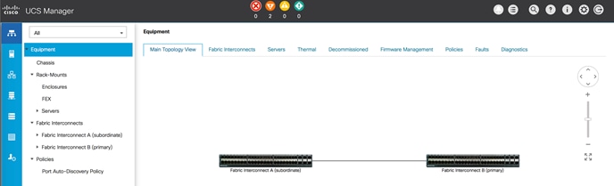
Cisco UCS Configuration
Configure the following ports, settings, and policies in the Cisco UCS Manager interface prior to beginning the HyperFlex installation.
Cisco UCS Firmware
Your Cisco UCS firmware version should be correct as shipped from the factory, as documented in the Software Components section. This document is based on Cisco UCS infrastructure, Cisco UCS B-series bundle, and Cisco UCS C-Series bundle software versions 4.0(4d). If the firmware version of the Fabric Interconnects is older than this version, the firmware must be upgraded to match the requirements prior to completing any further steps. To upgrade the Cisco UCS Manager version, the Fabric Interconnect firmware, and the server bundles, refer to these instructions:
NTP
To synchronize the Cisco UCS environment time to the NTP server, follow these steps:
1. In Cisco UCS Manager, click Admin.
2. In the navigation pane, choose All > Time Zone Management, and click the carat next to Time Zone Management to expand it.
3. Click Timezone.
4. In the Properties pane, choose the appropriate time zone in the Time Zone menu.
5. Click Add NTP Server.
6. Enter the NTP server IP address and click OK.
7. Click OK.
8. Click Save Changes and then click OK.
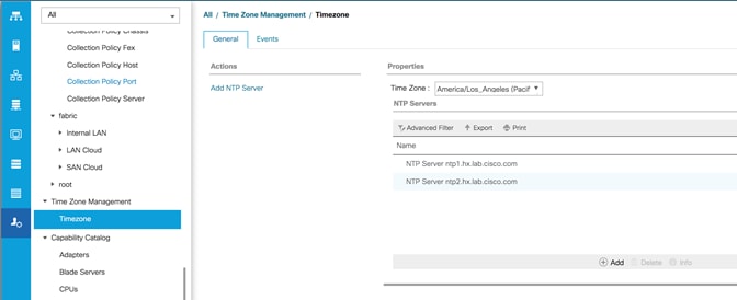
Uplink Ports
The Ethernet ports of a Cisco UCS Fabric Interconnect are all capable of performing several functions, such as network uplinks or server ports, and more. By default, all ports are unconfigured, and their function must be defined by the administrator. To define the specified ports to be used as network uplinks to the upstream network, follow these steps:
1. In Cisco UCS Manager, click Equipment.
2. Choose Fabric Interconnects > Fabric Interconnect A > Fixed Module or Expansion Module as appropriate > Ethernet Ports.
3. Choose the ports that are to be uplink ports, right-click them, and click Configure as Uplink Port.
4. Click Yes to confirm the configuration, then click OK.
5. Choose Fabric Interconnects > Fabric Interconnect B > Fixed Module or Expansion Module as appropriate > Ethernet Ports.
6. Choose the ports that are to be uplink ports, right-click them, and click Configure as Uplink Port.
7. Click Yes to confirm the configuration and click OK.
8. Verify all the necessary ports are now configured as uplink ports, where their role is listed as “Network”.
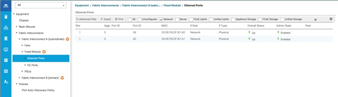
Uplink Port Channels
If the Cisco UCS uplinks from one Fabric Interconnect are to be combined into a port channel or vPC, you must separately configure the port channels, which will use the previously configured uplink ports. To configure the necessary port channels in the Cisco UCS environment, follow these steps:
1. In Cisco UCS Manager, click LAN.
2. Under LAN > LAN Cloud, click the carat to expand the Fabric A tree.
3. Right-click Port Channels underneath Fabric A, then click Create Port Channel.
4. Enter the port channel ID number as the unique ID of the port channel (this does not have to match the port-channel ID on the upstream switch).
5. Enter the name of the port channel.
6. Click Next.
7. Click each port from Fabric Interconnect A that will participate in the port channel, then click the >> button to add them to the port channel.
8. Click Finish.
9. Click OK.
10. Under LAN > LAN Cloud, click the carat to expand the Fabric B tree.
11. Right-click Port Channels underneath Fabric B, then click Create Port Channel.
12. Enter the port channel ID number as the unique ID of the port channel (this does not have to match the port-channel ID on the upstream switch).
13. Enter the name of the port channel.
14. Click Next.
15. Click each port from Fabric Interconnect B that will participate in the port channel, then click the >> button to add them to the port channel.
16. Click Finish.
17. Click OK.
18. Verify the necessary port channels have been created. It can take a few minutes for the newly formed port channels to converge and come online.
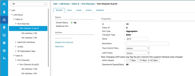
Chassis Discovery Policy
If the Cisco HyperFlex system will use blades as compute-only nodes in an extended cluster design, additional settings must be configured for connecting the Cisco UCS 5108 blade chassis. The Chassis Discovery policy defines the number of links between the Fabric Interconnect and the Cisco UCS Fabric Extenders which must be connected and active, before the chassis will be discovered. This also effectively defines how many of those connected links will be used for communication. The Link Grouping Preference setting specifies if the links will operate independently, or if Cisco UCS Manager will automatically combine them into port-channels. Cisco best practices recommends using link grouping, and the number of links per side is dependent on the hardware used in Cisco UCS 5108 chassis, and the model of Fabric Interconnects. For 10 GbE connections Cisco recommends 4 links per side, and for 40 GbE connections Cisco recommends 2 links per side.
To configure the necessary policy and setting, follow these steps:
1. In Cisco UCS Manager, click Equipment, then click Equipment.
2. In the properties pane, click the Policies tab.
3. Under the Global Policies sub-tab, set the Chassis/FEX Discovery Policy to match the number of uplink ports that are cabled per side, between the chassis and the Fabric Interconnects.
4. Set the Link Grouping Preference option to Port Channel.
5. Set the backplane speed preference to 4x10 Gigabit or 40 Gigabit.
6. Click Save Changes.
7. Click OK.
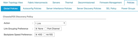
Server Ports
The Ethernet ports of a Cisco UCS Fabric Interconnect connected to the rack-mount servers, or to the blade chassis must be defined as server ports. When a server port is activated, the connected server or chassis will begin the discovery process shortly afterwards. Rack-mount servers and blade chassis are automatically numbered in Cisco UCS Manager in the order which they are first discovered. For this reason, it is important to configure the server ports sequentially in the order you wish the physical servers and/or chassis to appear within Cisco UCS Manager. For example, if you installed your servers in a cabinet or rack with server #1 on the bottom, counting up as you go higher in the cabinet or rack, then you need to enable the server ports to the bottom-most server first, and enable them one-by-one as you move upward. You must wait until the server appears in the Equipment tab of Cisco UCS Manager before configuring the ports for the next server. The same numbering procedure applies to blade server chassis, although chassis and rack-mount server numbers are separate from each other.
Auto Configuration
A new feature in Cisco UCS Manager 3.1(3a) and later is Server Port Auto-Discovery, which automates the configuration of ports on the Fabric Interconnects as server ports when a Cisco UCS rack-mount server or blade chassis is connected to them. The firmware on the rack-mount servers or blade chassis Fabric Extenders must already be at version 3.1(3a) or later in order for this feature to function properly. Enabling this policy eliminates the manual steps of configuring each server port, however it can configure the servers in a somewhat random order depending upon the circumstances. An example of how to use this feature in an orderly manner would be to have the policy already set, then to mount, cable and apply power to each new server one-by-one. In this scenario the servers should be automatically discovered in the order you racked them and applied power.
An example of how the policy can result in unexpected ordering would be when the policy has not been enabled, then all of the new servers are racked, cabled and have power applied to them. If the policy is enabled afterwards, it will likely not discover the servers in a logical order. For example, the rack-mount server at the bottom of the stack, which you may refer to as server #1, and you may have plugged into port 1 of both Fabric Interconnects, could be discovered as server 2, or server 5, and so on. In order to have fine control of the rack-mount server or chassis numbering and order in this scenario, the manual configuration steps listed in the next section must be followed.
To configure automatic server port definition and discovery, follow these steps:
1. In Cisco UCS Manager, click the Equipment button on the left-hand side.
2. In the navigation tree, under Policies, click Port Auto-Discovery Policy.
3. In the properties pane, set Auto Configure Server Port option to Enabled.
4. Click Save Changes.
5. Click OK.
6. Wait for a brief period, until the rack-mount servers appear in the Equipment tab underneath Equipment > Rack Mounts > Servers, or the chassis appears underneath Equipment > Chassis.
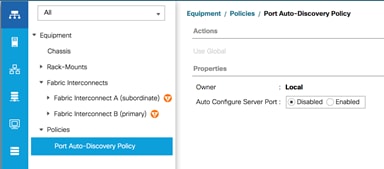
Manual Configuration
To manually define the specified ports to be used as server ports, and have control over the numbering of the servers, follow these steps:
1. In Cisco UCS Manager, click Equipment.
2. Choose Fabric Interconnects > Fabric Interconnect A > Fixed Module or Expansion Module as appropriate > Ethernet Ports.
3. Choose the first port that is to be a server port, right click it, and click Configure as Server Port.
4. Click Yes to confirm the configuration and click OK.
5. Choose Fabric Interconnects > Fabric Interconnect B > Fixed Module or Expansion Module as appropriate > Ethernet Ports.
6. Choose the matching port as chosen for Fabric Interconnect A that is to be a server port, right-click it and click Configure as Server Port.
7. Click Yes to confirm the configuration and click OK.
8. Wait for a brief period, until the rack-mount server appears in the Equipment tab underneath Equipment > Rack Mounts > Servers, or the chassis appears underneath Equipment > Chassis.
9. Repeat Steps 1-8 for each pair of server ports, until all rack-mount servers and chassis appear in the order desired in the Equipment tab.
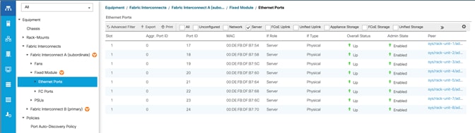
Server Discovery
As previously described, when the server ports of the Fabric Interconnects are configured and active, the servers connected to those ports will begin a discovery process. During discovery, the servers’ internal hardware inventories are collected, along with their current firmware revisions. Before continuing with the HyperFlex installation processes, which will create the service profiles and associate them with the servers, wait for all of the servers to finish their discovery process and to show as unassociated servers that are powered off, with no errors.
To view the servers’ discovery status, follow these steps:
1. In Cisco UCS Manager, click Equipment and then click Equipment at the top of the navigation tree.
2. In the properties pane, click the Servers tab.
3. Click the Blade Servers or Rack-Mount Servers sub-tab as appropriate, then view the servers’ status in the Overall Status column.
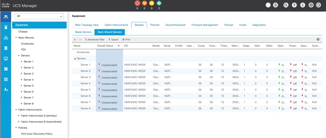
HyperFlex Installer VM Deployment
The Cisco HyperFlex software is distributed as a deployable virtual machine, contained in an Open Virtual Appliance (OVA) file format. The HyperFlex OVA file is available for download at cisco.com:
https://software.cisco.com/download/home/286305544/type/286305994/release/4.0(1b)
This document is based on the Cisco HyperFlex 4.0(1b) release filename: Cisco-HX-Data-Platform-Installer-v4.0.2a-33133-esx.ova
The HyperFlex installer OVA file can be deployed as a virtual machine in an existing VMware vSphere environment, VMware Workstation, VMware Fusion, or other virtualization environment which supports importing of OVA format files. For the purpose of this document, the process described uses an existing ESXi server managed by vCenter to run the HyperFlex installer OVA and deploying it via the VMware vSphere Web Client.
Installer Connectivity
The Cisco HyperFlex Installer VM must be deployed in a location that has connectivity to the following network locations and services:
· Connectivity to the vCenter Server which will manage the HyperFlex cluster(s) to be installed.
· Connectivity to the management interfaces of the Fabric Interconnects that contain the HyperFlex cluster(s) to be installed.
· Connectivity to the management interface of the ESXi hypervisor hosts which will host the HyperFlex cluster(s) to be installed.
· Connectivity to the DNS server(s) which will resolve host names used by the HyperFlex cluster(s) to be installed.
· Connectivity to the NTP server(s) which will synchronize time for the HyperFlex cluster(s) to be installed.
· Connectivity from the staff operating the installer to the webpage hosted by the installer, and to log in to the installer via SSH.
For complete details of all ports required for the installation of Cisco HyperFlex, refer to Appendix A of the HyperFlex 4.0 Hardening Guide: https://www.cisco.com/c/dam/en/us/support/docs/hyperconverged-infrastructure/hyperflex-hx-data-platform/HX-Hardening_Guide.pdf
If the network where the HyperFlex installer VM is deployed has DHCP services available to assign the proper IP address, subnet mask, default gateway, and DNS servers, the HyperFlex installer can be deployed using DHCP. If a static address must be defined, use Table 45 to document the settings to be used for the HyperFlex installer VM:
Table 45 HyperFlex Installer Settings
| Setting |
Value |
| IP Address |
|
| Subnet Mask |
|
| Default Gateway |
|
| DNS Server |
|
| NTP Server(s) |
|
| Root Password |
|
Deploy Installer OVA
To deploy the HyperFlex installer OVA, follow these steps:
1. Open the vSphere HTML5 Web Client webpage of a vCenter server where the installer OVA will be deployed and log in with admin privileges.
2. In the vSphere Web Client, from the Home view, click Hosts and Clusters.
3. From the Actions menu, click Deploy OVF Template.
4. Choose the Local file option, then click the Choose Files button and locate the Cisco-HX-Data-Platform-Installer-v4.0.2a-33133-esx.ova file, click the file and click Open.
5. Click Next.
6. Modify the name of the virtual machine to be created if desired and click a folder location to place the virtual machine, then click Next.
7. Click a specific host or cluster to locate the virtual machine and click Next.
8. After the file validation, review the details and click Next.
9. Choose a Thin provision virtual disk format, and the datastore to store the new virtual machine, then click Next.
10. Modify the network port group selection from the drop-down list in the Destination Networks column, choosing the network the installer VM will communicate on, and click Next.
11. If DHCP is to be used for the installer VM, leave the fields blank, except for the NTP server value and click Next. If static address settings are to be used, fill in the fields for the DNS server, Default Gateway, NTP Servers, IP address, and subnet mask.
12. Enter and confirm a new password used to log in to the installer VM after it is deployed, then click Next.
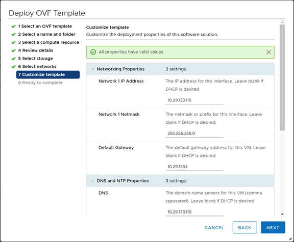
13. Review the final configuration and click Finish.
14. The installer VM will take a few minutes to deploy, once it has deployed, power on the new VM and proceed to the next step.
HyperFlex Installer Web Page
The HyperFlex installer is accessed via a webpage using your local computer and a web browser. If the HyperFlex installer was deployed with a static IP address, then the IP address of the website is already known. If DHCP was used, open the local console of the installer VM. In the console, you will see an interface similar to the example below, showing the IP address that was leased:
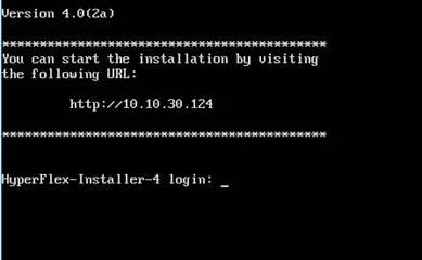
To access the HyperFlex installer webpage, follow these steps:
1. Open a web browser on the local computer and navigate to the IP address of the installer VM. For example, open http://10.29.132.115
2. Click accept or continue to bypass any SSL certificate errors.
3. At the login screen, enter the username: root
4. At the login screen, enter the password which was set during the OVA deployment.
5. Verify the version of the installer in the lower right-hand corner of the Welcome page is the correct version.
6. Check the box for “I accept the terms and conditions” and click Login.
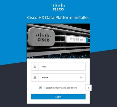
Cisco HyperFlex Cluster Configuration
To configuring the Cisco HyperFlex Cluster, follow this step:
1. Log into the HX Installer virtual machine through a web browser: Error! Hyperlink reference not valid.>.
Create a HyperFlex Cluster
1. Choose the workflow for cluster creation to deploy a new HyperFlex cluster on eight Cisco HXAF220c-M5S nodes.
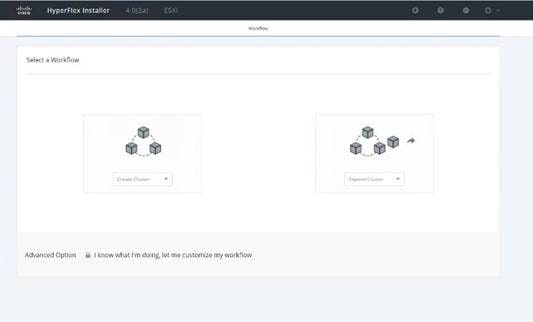
2. On the credentials page, enter the access details for Cisco UCS Manager, vCenter server, and Hypervisor. Click Continue.
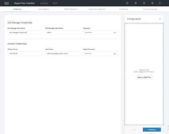
3. Choose the top-most check box at the top right corner of the HyperFlex installer to select all unassociated servers. (To configure a subset of available of the HyperFlex servers, manually click the check box for individual servers.)
4. Click Continue after completing server selection.
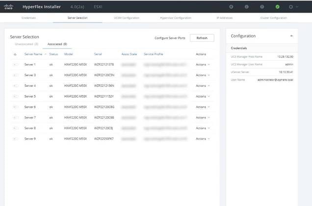
![]() Note: The required server ports can be configured from Installer workflow but it will extend the time to complete server discovery. Therefore, we recommend configuring the server ports and complete HX node discovery in Cisco UCS Manager as described in the Pre-requisites section above prior starting workflow for HyperFlex installer.
Note: The required server ports can be configured from Installer workflow but it will extend the time to complete server discovery. Therefore, we recommend configuring the server ports and complete HX node discovery in Cisco UCS Manager as described in the Pre-requisites section above prior starting workflow for HyperFlex installer.
Configure Server Ports (Optional)
If you choose to allow the installer to configure the server ports, follow these steps:
1. Click Configure Server Ports at the top right corner of the Server Selection window.
2. Provide the port numbers for each Fabric Interconnect in the form:
A1/x-y,B1/x-y where A1 and B1 designate Fabric Interconnect A and B and where x=starting port number and y=ending port number on each Fabric Interconnect.
3. Click Configure.
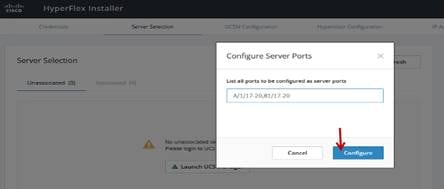
4. Enter the Details for the Cisco UCS Manager Configuration:
a. Enter the VLAN ID for hx-inband-mgmt, hx-storage-data, hx-vmotion, vm-network.
b. MAC Pool Prefix: The prefix to use for each HX MAC address pool. Please select a prefix that does not conflict with any other MAC address pool across all Cisco UCS domains.
c. The blocks in the MAC address pool will have the following format:
- ${prefix}:${fabric_id}${vnic_id}:{service_profile_id}
- The first three bytes should always be “00:25:B5”.
![]() Note: The first three bytes should always be “00:25:B5.”
Note: The first three bytes should always be “00:25:B5.”
5. Enter range of IP address to create a block of IP addresses for external management and access to CIMC/KVM.
6. Cisco UCS firmware version is set to 4.0 (1b) which is the required Cisco UCS Manager release for HyperFlex v3.5(1a) installation.
7. Enter HyperFlex cluster name.
8. Enter Org name to be created in Cisco UCS Manager.
9. Click Continue.
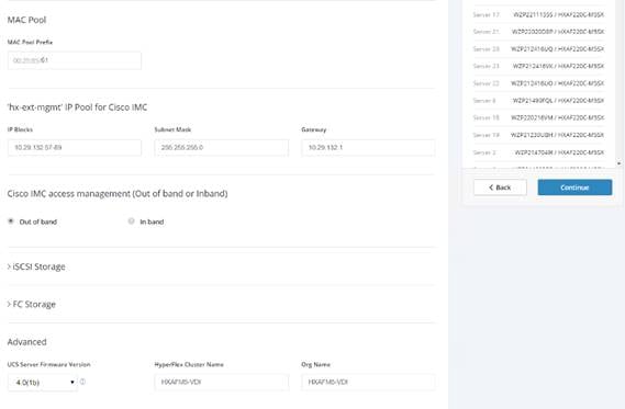
Configure Hypervisor Settings
To configure the Hypervisor settings, follow these steps:
1. In the Configure common Hypervisor Settings section, enter:
- Subnet Mask
- Gateway
- DNS server(s)
2. In the Hypervisor Settings section:
- Choose check box Make IP Address and Hostnames Sequential if they are following in sequence.
- Provide the starting IP Address.
- Provide the starting Host Name or enter Static IP address and Host Names manually for each node
3. Click Continue.
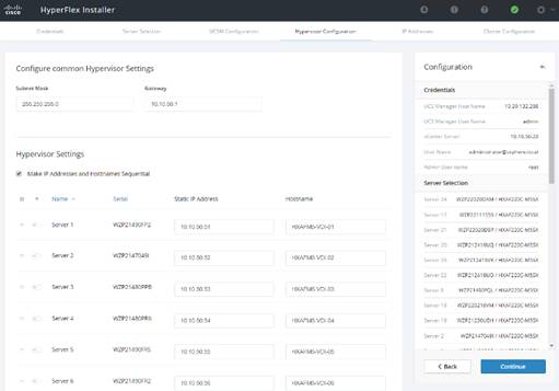
IP Addresses
To add the IP addresses, follow these steps:
![]() Note: When the IP Addresses page appears, the hypervisor IP address for each node that was configured in the Hypervisor Configuration tab, appears under the Management Hypervisor column.
Note: When the IP Addresses page appears, the hypervisor IP address for each node that was configured in the Hypervisor Configuration tab, appears under the Management Hypervisor column.
Three additional columns appear on this page:
· Storage Controller/Management
· Hypervisor/Data
· Storage Controller/Data
![]() Note: The Data network IP addresses are for vmkernel addresses for storage access by the hypervisor and storage controller virtual machine.
Note: The Data network IP addresses are for vmkernel addresses for storage access by the hypervisor and storage controller virtual machine.
1. On the IP Addresses page, check the box Make IP Addresses Sequential or enter the IP address manually for each node for the following requested values:
- Storage Controller/Management
- Hypervisor/Data
- Storage Controller/Data
2. Enter subnet and gateway details for the Management and Data subnets configured.
3. Click Continue to proceed.
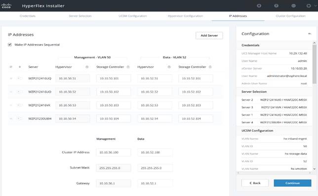
4. On the Cluster Configuration page, enter the following:
- Cluster Name
- Cluster management IP address
- Cluster data IP Address
- Set Replication Factor: 2 or 3
- Controller virtual machine password
- vCenter configuration
§ vCenter Datacenter name
§ vCenter Cluster name
- System Services
§ DNS Server(s)
§ NTP Server(s)
§ Time Zone
- Auto Support
§ Click the check box for Enable Auto Support
§ Mail Server
§ Mail Sender
§ ASUP Recipient(s)
- Advanced Networking
§ Management vSwitch
§ Data vSwitch
- Advanced Configuration
§ Click the check box to Optimize for VDI only deployment
§ Enable jumbo Frames on Data Network
§ Clean up disk partitions (optional)
- vCenter Single-Sign-On server
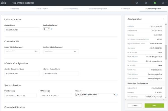
- vCenter Single-Sign-On server
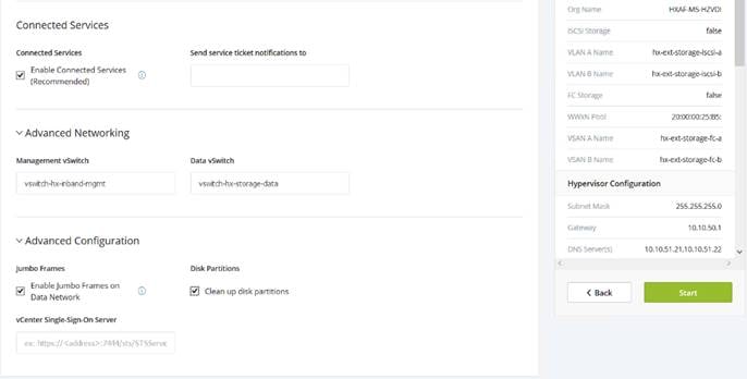
5. The configuration details can be exported to a JSON file by clicking the down arrow icon in the top right corner of the Web browser page as shown in the screenshot below.
6. Configuration details can be reviewed on Configuration page on right side section. Verify entered details for IP address entered in Credentials page, server selection for cluster deployment and creation workflow, Cisco UCS Manager configuration, Hypervisor Configuration, IP addresses.
7. Click Start after verifying details.
When the installation workflow begins, it will go through the Cisco UCS Manager validation.
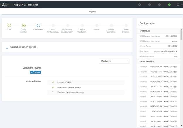
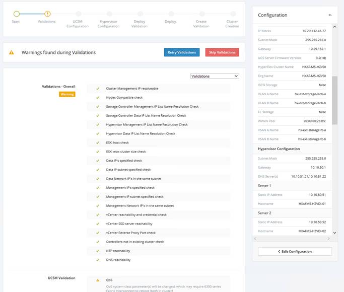
![]() Note: If QoS system class is not defined as per the requirement HyperFlex installer will go ahead and make required changes. There will be a warning generated accordingly in HyperFlex Installer workflow. For 6300 series Fabric Interconnect change in QoS system class requires reboot of FIs.
Note: If QoS system class is not defined as per the requirement HyperFlex installer will go ahead and make required changes. There will be a warning generated accordingly in HyperFlex Installer workflow. For 6300 series Fabric Interconnect change in QoS system class requires reboot of FIs.
8. After a successful validation, the workflow continues with the Cisco UCS Manager configuration.
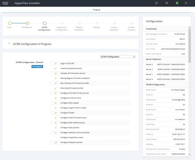
9. After a successful Cisco UCS Manager configuration, the installer proceeds with the Hypervisor configuration.
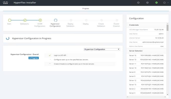
10. After a successful Hypervisor configuration, the deploy validation task is performed which checks for the required component and accessibility prior Deploy task is performed on Storage Controller virtual machine.
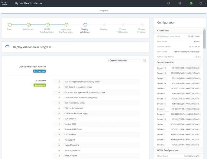
11. Installer performs deployment task after successfully validating Hypervisor configuration.
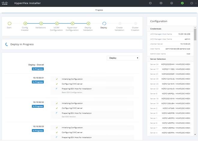
12. After a successful deployment of the ESXi hosts configuration, the Controller virtual machine software components for HyperFlex installer checks for validation prior to creating the cluster.
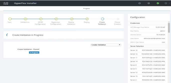
13. After a successful validation, the installer creates and starts the HyperFlex cluster service.
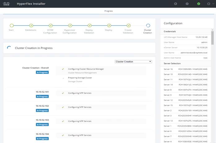
14. After a successful HyperFlex Installer virtual machine workflow completion, the installer GUI provides a summary of the cluster that has been created.
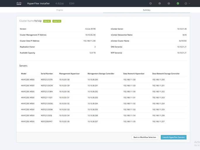
Cisco HyperFlex Cluster Expansion
![]() Note: For this exercise, you will add the compute node workflow as part of the cluster expansion.
Note: For this exercise, you will add the compute node workflow as part of the cluster expansion.
Prerequisites
Configure the service profile for compute-only nodes and install ESXi hypervisor.
To add the compute node workflow, follow these steps:
1. Log into Cisco UCS Manger.
2. Under “hx-cluster” sub-organization:
a. In the existing vMedia policy “HyperFlex” add vMedia mount details to boot ESXi image from data platform installer virtual machine.
b. For Hostname/IP Address – Add IP address of data-platform installer virtual machine which can also communicate with Cisco UCS Manager.
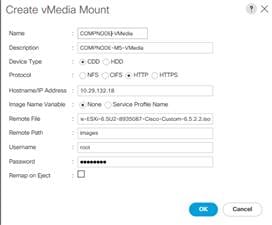
3. Change the existing service profile template to accommodate the new changes; install ESXi through vMedia policy.
4. In the existing service profile template “compute-nodes” choose vMedia Policy tab.
5. Click Modify vMedia Policy.
6. From the drop-down list of vMedia Policy, choose HyperFlex.
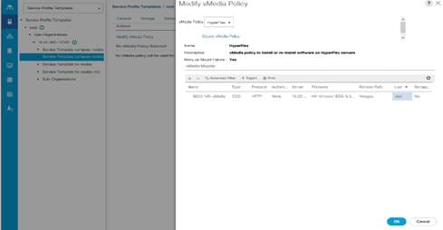
7. In the existing service profile template “compute-nodes” click Boot Order tab.
8. Click Modify Boot Policy.
9. From the drop-down list of Boot Policies, choose HyperFlexInstall.
10. Save changes.
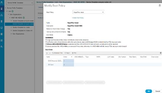
11. Create the service profile from the “compute-nodes” updating service profile template located in the HyperFlex cluster sub organization.
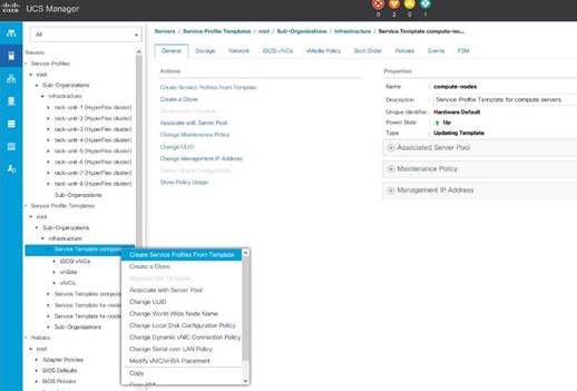
12. Add the Naming Prefix and Number of Instances to be created.
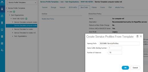
13. Click OK.
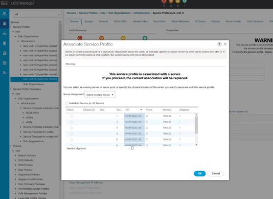
14. After the of ESXi install, assign the VLAN tag on the ESXi host; the static IP address configuration is located in the Configure Management Network section.
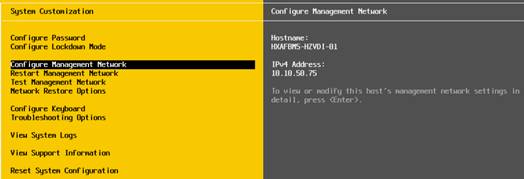
15. Log into the HyperFlex data platform installer WebUI. Click “I know what I'm doing, let me customize my workflow.”
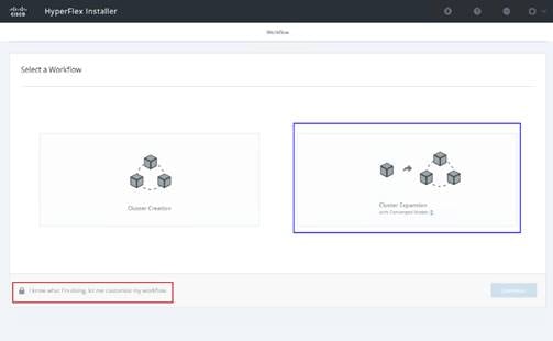
16. Choose Deploy HX Software, Expand HX Cluster. Click Continue.
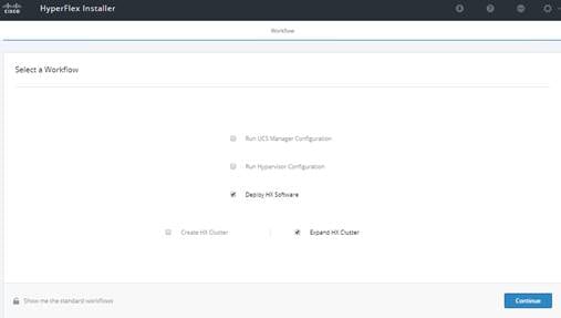
17. Enter the credentials for vCenter server, and ESXi. Click Continue.
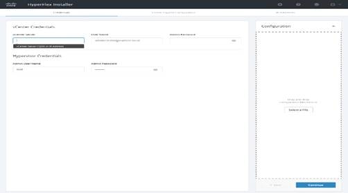
18. Choose Cluster to expand, click Continue.
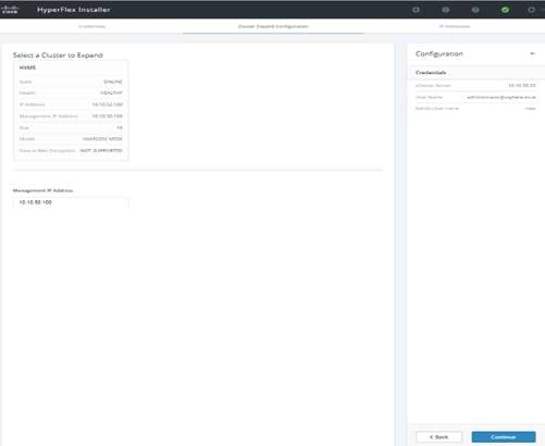
![]() Note: Since you are performing a compute-node only expansion, no servers report in to the Cisco UCS Manager configuration tab.
Note: Since you are performing a compute-node only expansion, no servers report in to the Cisco UCS Manager configuration tab.
19. Click Add Compute Server tab for N number of compute-only node expansion to existing HyperFlex cluster. Provide Hypervisor Management IP address and vmkernel IP address to access storage cluster. Click Continue.
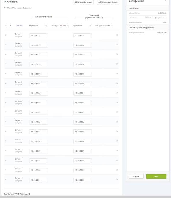
20. Cluster expansion workflow starts which performs deploy validation task first.
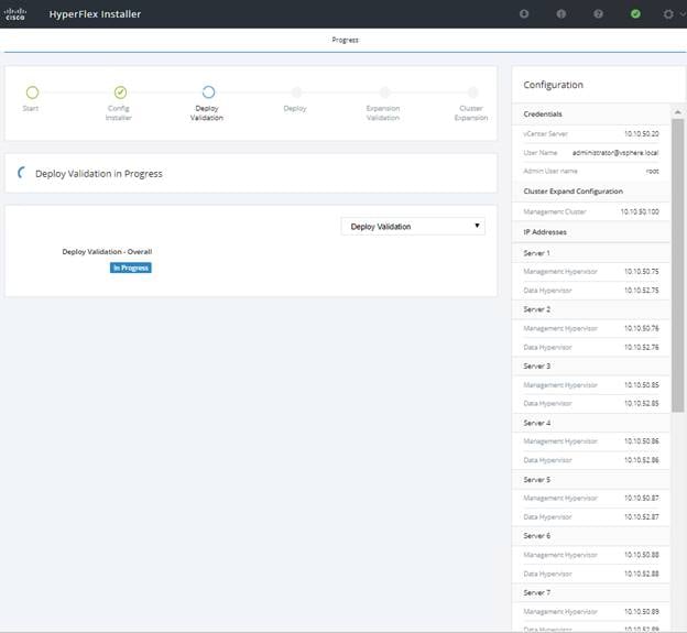
21. Performs deployment of HyperFlex controller virtual machine create and deployment task.
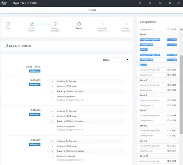
22. Performs expansion validation.
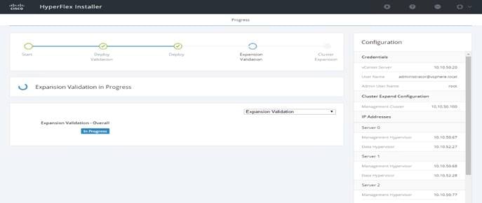
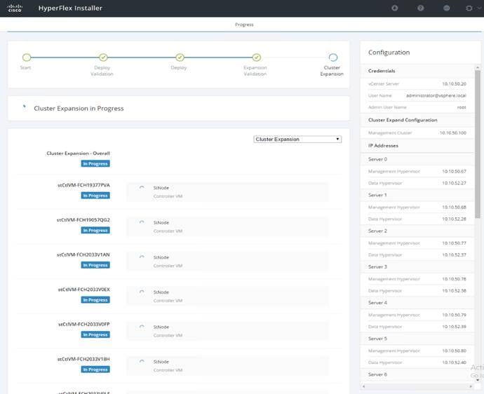
23. Summary of Expansion cluster workflow performed.
![]() Note: As part of the cluster creation operations, the HyperFlex Installer adds HyperFlex functionality to the vSphere vCenter identified in earlier steps. This functionality allows vCenter administrators to manage the HyperFlex cluster entirely from their vSphere Web Client.
Note: As part of the cluster creation operations, the HyperFlex Installer adds HyperFlex functionality to the vSphere vCenter identified in earlier steps. This functionality allows vCenter administrators to manage the HyperFlex cluster entirely from their vSphere Web Client.
24. Click Launch vSphere Web Client.
Cisco HyperFlex installer creates and configures a controller virtual machine on each converged or compute-only node. The naming convention used is “stctlvm-<Serial Number for Cisco UCS Node>” shown in Figure 42.
![]() Do not to change the name or any resource configuration for the controller virtual machine.
Do not to change the name or any resource configuration for the controller virtual machine.
Claim Devices in Intersight
The Cisco UCS Manager device connector allows Cisco Intersight to manage the Cisco UCS domain and all of the connected HyperFlex servers and claim them for cloud management.
To configure the claim devices, follow these steps:
1. Log into the Cisco UCS Manager web interface of the Cisco Fabric Interconnects which are connected to the Cisco HX-series servers that will comprise the new Cisco HyperFlex cluster being installed.
2. From the left-hand navigation pane click Admin, then click Device Connector.
3. Note that the Cisco UCS domain shows a status of “Not Claimed”. Copy the Device ID and the Claim Code by clicking on the small clipboard icons.
4. Open a web browser and navigate to the Cisco Intersight Cloud Management platform https://intersight.com/.
5. Login with your Cisco ID and password. If this is the first time using Intersight, it is recommended you take a site tour to be guided through some main features.
6. To Claim a new device, from the left-hand Navigation pane, click Devices, in the Device window, choose Claim a New Device at the right top corner.

7. Ensure the option for Direct Claim is chosen, then input the Device ID and Claim Code obtained from Cisco UCS management GUI. Use copy and paste for accuracy. Click Claim.

8. Wait until the device is claimed successfully and to appear in the list of devices.
9. Click the Refresh link in the Cisco UCS Manager Device Connector screen. The Device Connector now shows this device is claimed.
10. In the Device window, the Cisco UCS Fabric Interconnect domain should now show as connected devices.
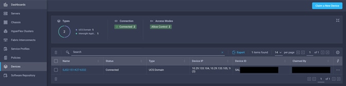
Post-install Configuration
Prior to putting a new HyperFlex cluster into production, a few post-install tasks must be completed. To automate the post installation procedures and verify the HyperFlex cluster configuration, a post_install script has been provided on the HyperFlex Controller VMs. To run this script, follow these steps:
1. SSH to the cluster management IP address and login using <root> username and the controller VM password provided during installation. Verify the cluster is online and healthy using “stcli cluster info” or “stcli cluster storage-summary”.
2. Run the following command in the shell, and press enter:
/usr/share/springpath/storfs-misc/hx-scripts/post_install.py
3. Choose the first post_install workflow type – New/Existing Cluster.
4. Enter the HX Storage Controller VM root password for the HX cluster (use the one entered during the HX Cluster installation).
5. Enter the vCenter server username and password.
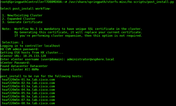
6. Enter ESXi host root password (use the one entered during the HX Cluster installation).
7. You must license the vSphere hosts through the script or complete this task in vCenter before continuing. Failure to apply a license will result in an error when enabling HA or DRS in subsequent steps. Enter “n” if you have already registered the license information in vCenter.
8. Enter “y” to enable HA/DRS.
9. Enter “y” to disable the ESXi hosts’ SSH warning. SSH running in ESXi is required in HXDP 2.6.
10. Add the vMotion VMkernel interfaces to each node by entering “y”. Input the netmask, the vMotion VLAN ID, and the vMotion IP addresses for each of the hosts as prompted.
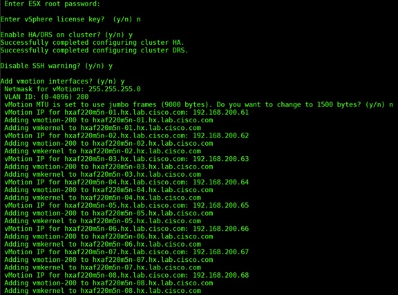
11. You may add VM network portgroups for guest VM traffic. Enter “n” to skip this step and create the portgroups manually in vCenter. Or if desired, VM network portgroups can be created and added to the vm-network vSwitch. This step will add identical network configuration to all nodes in the cluster.
12. Enter “y” to run the health check on the cluster.
13. A summary of the cluster will be displayed upon completion of the script. Make sure the cluster is healthy.
Initial Tasks and Testing
Datastores
Create a datastore for storing the virtual machines. This task can be completed by using the vSphere Web Client HX plugin, or by using the HyperFlex Connect HTML management webpage. To configure a new datastore via the HyperFlex Connect webpage, follow these steps:
1. Use a web browser to open the HX cluster IP management URL.
2. Enter a local credential, or a vCenter RBAC credential with administrative rights for the username, and the corresponding password.
3. Click Login.
4. Click Datastores and then click Create Datastore.
5. In the popup, enter the Datastore Name and size. For most applications, leave the Block Size at the default of 8K. Only dedicated Virtual Desktop Infrastructure (VDI) environments should choose the 4K Block Size option.
6. Click Create Datastore.
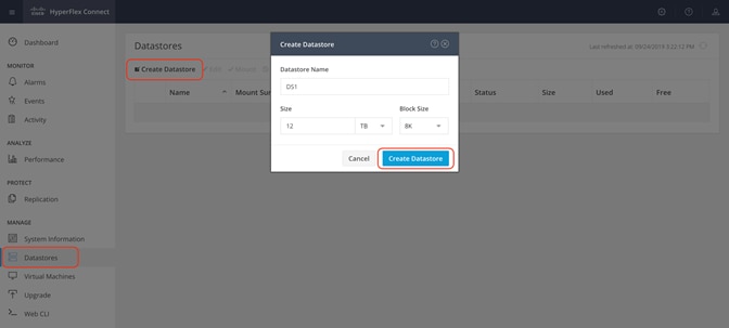
Create VM
In order to perform the initial testing and to learn about the features in the HyperFlex cluster, create a test virtual machine stored on your new HX datastore in order to take a snapshot and perform a cloning operation.
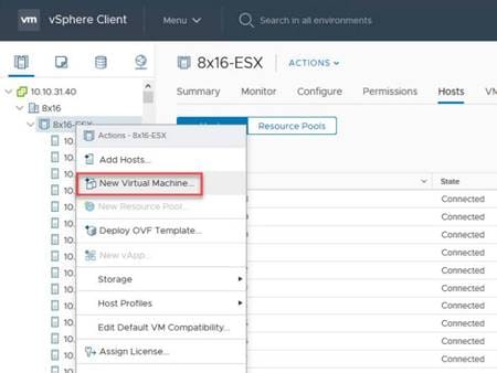
Snapshots
Take a snapshot of the new virtual machine prior to powering it on.
To take an instant snapshot of a VM, follow these steps:
1. In the HyperFlex Connect webpage, click the Virtual Machines menu, then click the name of the VM to snapshot.
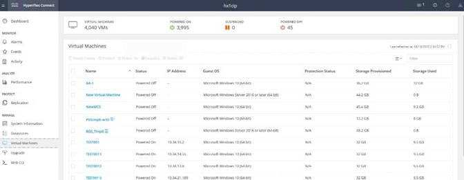
2. Click the Actions drop-down list, then choose Snapshot Now.
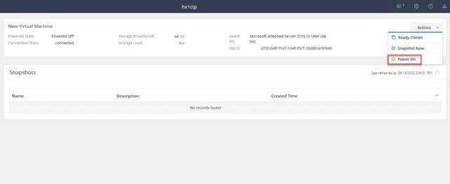
3. Input the snapshot name, a description if desired, and choose whether to quiesce the VM, then click Snapshot Now.
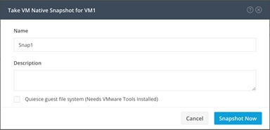
Ready Clones
Create a few clones of our test virtual machine.
To create the Ready Clones, follow these steps:
1. In the HyperFlex Connect webpage, click the Virtual Machines menu, click the checkbox to choose the VM to clone, then click Ready Clones.
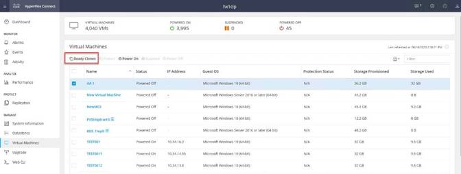
2. Input the Number of clones to create, a customization specification if needed, a resource pool if needed, and a naming prefix, then click Clone to start the operation. The clones will be created in seconds.
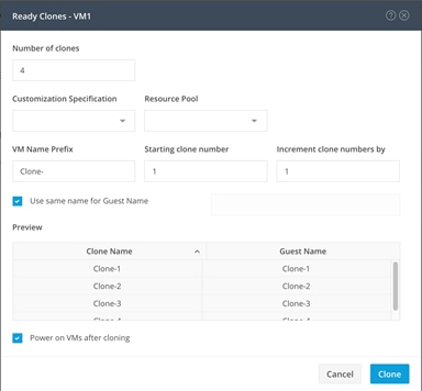
Audit Logging
By default, the HyperFlex controller VMs store logs locally for many functions, including the filesystem logs, security auditing, CLI commands and shell access, single sign-on logs, and more. These logs are rotated periodically and could be lost if there were a total failure of a controller VM. In order to store these logs externally from the HyperFlex cluster, audit logging can be enabled in HX Connect to send copies of these logs to an external syslog server. From this external location, logs can be monitored, generate alerts, and stored long term. HX Connect will not monitor the available disk space on the syslog destination, nor will it generate an alarm if the destination server is full. To enable audit logging, follow these steps:
1. Use a web browser to open the HX cluster IP management URL.
2. From the HyperFlex Connect webpage, click the gear shaped icon in the upper right-hand corner, and click Audit Log Export Settings.
3. Click to check the box to Enable audit log export to an external syslog server.
4. Enter the syslog server IP address and TCP port.
5. Choose TCP or TLS as the connection type. If using TLS, client certificate and private key pair files must be provided. Alternatively, a self-signed certificate can be used. Click browse to choose the appropriate files.
6. Click OK.
![]() Note: Audit log exports can be temporarily disabled or completely deleted at a later time from the same location.
Note: Audit log exports can be temporarily disabled or completely deleted at a later time from the same location.
To store ESXi diagnostic logs in a central location in case they are needed to help diagnose a host failure, it is recommended to enable a syslog destination for permanent storage of the ESXi host logs for all Cisco HyperFlex hosts. It is possible to use the vCenter server as the log destination in this case, or another syslog receiver of your choice.
To configure syslog for ESXi, follow these steps:
1. Log into the ESXi host via SSH as the root user.
2. Enter the following commands, replacing the IP address in the first command with the IP address of the vCenter server that will receive the syslog logs:
[root@hx220-01:~] esxcli system syslog config set --loghost='udp://10.29.132.120'
[root@hx220-01:~] esxcli system syslog reload
[root@hx220-01:~] esxcli network firewall ruleset set -r syslog -e true
[root@hx220-01:~] esxcli network firewall refresh
3. Repeat for each ESXi host.
Auto-Support and Notifications
Auto-Support should be enabled for all clusters during the initial HyperFlex installation. Auto-Support enables Call Home to automatically send support information to Cisco TAC, and notifications of tickets to the email address specified. If the settings need to be modified, they can be changed in the HyperFlex Connect HTML management webpage.
A list of events that will automatically open a support ticket with Cisco TAC is as follows:
· Cluster Capacity Changed
· Cluster Unhealthy
· Cluster Health Critical
· Cluster Read Only
· Cluster Shutdown
· Space Warning
· Space Alert
· Space Critical
· Disk Blacklisted
· Infrastructure Component Critical
· Storage Timeout
To change Auto-Support settings, follow these steps:
1. From the HyperFlex Connect webpage, click the gear shaped icon in the upper right-hand corner, and click Auto-Support Settings.
2. Enable or disable Auto-Support as needed.
3. Enter the email address to receive alerts when Auto-Support events are generated.
4. Enable or disable Remote Support as needed. Remote support allows Cisco TAC to connect to the HX cluster and accelerate troubleshooting efforts.
5. Enter in the information for a web proxy if needed.
6. Click OK.
![]() Note: Email notifications that come directly from the HyperFlex cluster can also be enabled.
Note: Email notifications that come directly from the HyperFlex cluster can also be enabled.
To enable direct email notifications, follow these steps:
1. From the HyperFlex Connect webpage, click the gear shaped icon in the upper right-hand corner, and click Notifications Settings.
2. Enter the DNS name or IP address of the outgoing email server or relay, the email address the notifications will come from, and the recipients.
3. Click OK.
Smart Licensing
HyperFlex 2.5 and later utilizes Cisco Smart Licensing, which communicates with a Cisco Smart Account to validate and check out HyperFlex licenses to the nodes, from the pool of available licenses in the account. At the beginning, Smart Licensing is enabled but the HX storage cluster is unregistered and in a 90-day evaluation period or EVAL MODE. For the HX storage cluster to start reporting license consumption, it must be registered with the Cisco Smart Software Manager (SSM) through a valid Cisco Smart Account. Before beginning, verify that you have a Cisco Smart account, and valid HyperFlex licenses are available to be checked out by your HX cluster.
To create a Smart Account, see Cisco Software Central > Request a Smart Account https://webapps.cisco.com/software/company/smartaccounts/home?route=module/accountcreation .
To activate and configure smart licensing, follow these steps:
1. Log into a controller VM. Confirm that your HX storage cluster is in Smart Licensing mode.
# stcli license show status
Smart Licensing is ENABLED
Registration:
Status: UNREGISTERED
Export-Controlled Functionality: Not Allowed
License Authorization:
Status: EVAL MODE
Evaluation Period Remaining: 88 days, 1 hr, 33 min, 41 sec
Last Communication Attempt: NONE
License Conversion:
Automatic Conversion Enabled: true
Status: NOT STARTED
Utility:
Status: DISABLED
Transport:
Type: TransportCallHome
2. Feedback will show Smart Licensing is ENABLED, Status: UNREGISTERED, and the amount of time left during the 90-day evaluation period (in days, hours, minutes, and seconds).
3. Navigate to Cisco Software Central (https://software.cisco.com/) and log in to your Smart Account.
4. From Cisco Smart Software Manager, generate a registration token.
5. In the License pane, click Smart Software Licensing to open Cisco Smart Software Manager.
6. Click Inventory.
7. From the virtual account where you want to register your HX storage cluster, click General, and then click New Token.
8. In the Create Registration Token dialog box, add a short Description for the token, enter the number of days you want the token to be active and available to use on other products, and check Allow export-controlled functionality on the products registered with this token.
9. Click Create Token.
10. From the New ID Token row, click the Actions drop-down list, and click Copy.
11. Log into a controller VM.
12. Register your HX storage cluster, where idtoken-string is the New ID Token from Cisco Smart Software Manager.
# stcli license register --idtoken idtoken-string
13. Confirm that your HX storage cluster is registered.
# stcli license show summary
The cluster is now ready. You may run any other preproduction tests that you wish to run at this point.
ESXi Hypervisor Installation
HX nodes come from the factory with a copy of the ESXi hypervisor pre-installed, however there are scenarios where it may be necessary to redeploy or reinstall ESXi on an HX node. In addition, this process can be used to deploy ESXi on rack mount or blade servers that will function as HX compute-only nodes. The HyperFlex system requires a Cisco custom ESXi ISO file to be used, which has Cisco hardware specific drivers pre-installed, and customized settings configured to ease the installation process. The Cisco custom ESXi ISO file is available to download at cisco.com.
ESXi Kickstart ISO
The HX custom ISO is based on the Cisco custom ESXi 6.7 Update 3 ISO release with the filename: HX-ESXi-6.7U3-15160138-Cisco-Custom-6.7.3.3-install-only.iso and is available on the Cisco web site:
https://software.cisco.com/download/home/286305544/type/286305994/release/4.0(2a)
The custom Cisco HyperFlex ESXi ISO will automatically perform the following tasks with no user interaction required:
· Accept the End User License Agreement
· Configure the root password to: Cisco123
· Install ESXi to the internal mirrored Cisco FlexFlash SD cards, or the internal M.2 SSD
· Set the default management network to use vmnic0, and obtain an IP address via DHCP
· Enable SSH access to the ESXi host
· Enable the ESXi shell
· Enable serial port com1 console access to facilitate Serial over LAN access to the host
· Configure the ESXi configuration to always use the current hardware MAC address of the network interfaces, even if they change
· Rename the default vSwitch to vswitch-hx-inband-mgmt
Reinstall HX Cluster
If a Cisco HyperFlex cluster needs to be reinstalled, contact your local Cisco account or support team in order to be provided with a cluster cleanup guide. Note that the process will be destructive and result in the loss of all the VMs and all the data stored in the HyperFlex distributed filesystem.
A high-level example of an HX rebuild procedure is as follows:
1. Clean up the existing environment by:
a. Delete the existing HX virtual machines and HX datastores.
b. Destroy the HX cluster.
c. Remove the HX cluster from vCenter.
d. Remove the vCenter MOB entries for the HX extension.
e. Delete the HX sub-organization and HX VLANs in Cisco UCS Manager.
2. Using the HX OVA-based installer VM, use the customized version of the installation workflow by selecting the “I know what I am doing” link.
3. Use customized workflow and only choose the “Run UCS Manager Configuration” option, click Continue.
4. When the Cisco UCS Manager configuration is complete, HX hosts are associated with HX service profiles and powered on. Now perform a fresh ESXi installation using the custom ISO image and following the steps in section Cisco UCS vMedia and Boot Policies.
5. When the ESXi fresh installations are all finished, use the customized workflow and choose the remaining 3 options; ESXi Configuration, Deploy HX Software, and Create HX Cluster, to continue and complete the HyperFlex cluster installation.
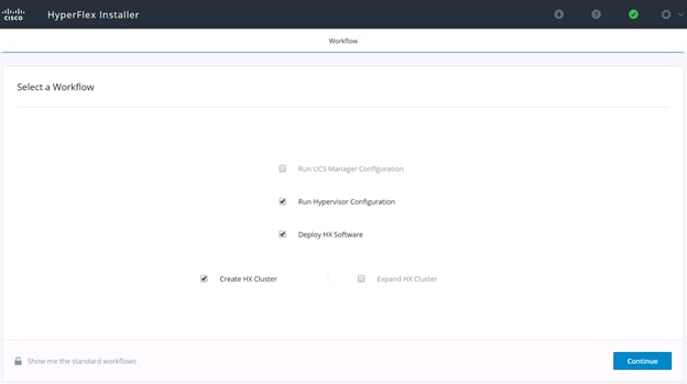
Cisco UCS vMedia and Boot Policies
By using a Cisco UCS vMedia policy, the custom Cisco HyperFlex ESXi installation ISO file can be mounted to all of the HX servers automatically. The existing vMedia policy, named “HyperFlex” must be modified to mount this file, and the boot policy must be modified temporarily to boot from the remotely mounted vMedia file. Once these two tasks are completed, the servers can be rebooted, and they will automatically boot from the remotely mounted vMedia file, installing and configuring ESXi on the servers.
![]() WARNING! While vMedia policies are very efficient for installing multiple servers, using vMedia policies as described could lead to an accidental reinstall of ESXi on any existing server that is rebooted with this policy applied. Please be certain that the servers being rebooted while the policy is in effect are the servers you wish to reinstall. Even though the custom ISO will not continue without a secondary confirmation, extreme caution is recommended. This procedure needs to be carefully monitored and the boot policy should be changed back to original settings immediately after the intended servers are rebooted, and the ESXi installation begins. Using this policy is only recommended for new installs or rebuilds. Alternatively, you can manually choose the boot device using the KVM console during boot, and pressing F6, instead of making the vMedia device the default boot selection.
WARNING! While vMedia policies are very efficient for installing multiple servers, using vMedia policies as described could lead to an accidental reinstall of ESXi on any existing server that is rebooted with this policy applied. Please be certain that the servers being rebooted while the policy is in effect are the servers you wish to reinstall. Even though the custom ISO will not continue without a secondary confirmation, extreme caution is recommended. This procedure needs to be carefully monitored and the boot policy should be changed back to original settings immediately after the intended servers are rebooted, and the ESXi installation begins. Using this policy is only recommended for new installs or rebuilds. Alternatively, you can manually choose the boot device using the KVM console during boot, and pressing F6, instead of making the vMedia device the default boot selection.
To configure the Cisco UCS vMedia and Boot Policies, follow these steps:
1. Copy the HX-ESXi-6.7U3-15160138-Cisco-Custom-6.7.3.3-install-only.iso file to an available web server folder, NFS share or CIFS share. In this example, an open internal web server folder is used.
2. In Cisco UCS Manager, click the Servers button on the left-hand side of the screen.
3. Expand Servers > Policies > root > Sub-Organizations > <<HX_ORG>> > vMedia Policies, and click vMedia Policy HyperFlex.
4. In the configuration pane, click Create vMedia Mount.
5. Enter a name for the mount, for example: ESXi.
6. Choose the CDD option.
7. Choose CIFS as the protocol.
8. Enter the IP address of the CIFS server where the file was copied, for example: 10.29.132.120
9. Choose None as the Image Variable Name.
10. Enter HX-ESXi-6.7U3-15160138-Cisco-Custom-6.7.3.3-install-only.iso as the Remote File.
11. Enter the Remote Path to the installation file.
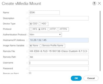
12. Click OK.
13. Choose Servers > Service Profile Templates > root > Sub-Organizations > <<HX_ORG>> > Service Template hx-nodes.
14. In the configuration pane, click the vMedia Policy tab.
15. Click Modify vMedia Policy.
16. Chose the HyperFlex vMedia Policy from the drop-down selection and click OK twice.
17. For Compute-Only nodes (if necessary), choose Servers > Service Profile Templates > root > Sub-Organizations > <<HX_ORG>> > Service Template compute-nodes.
18. In the configuration pane, click the vMedia Policy tab.
19. Click Modify vMedia Policy.
20. Chose the HyperFlex vMedia Policy from the drop-down selection and click OK twice.
21. Choose Servers > Policies > root > Sub-Organizations > <<HX_ORG>> > Boot Policy HyperFlex.
22. In the navigation pane, expand the section titled CIMC Mounted vMedia.
23. Click the entry labeled Add CIMC Mounted CD/DVD.
24. Choose the CIMC Mounted CD/DVD entry in the Boot Order list, and click the Move Up button until the CIMC Mounted CD/DVD entry is listed first.
25. Click Save Changes and click OK.
Install ESXi
To begin the installation after modifying the vMedia policy, Boot policy and service profile template, the servers need to be rebooted. To complete the reinstallation, it is necessary to open a remote KVM console session to each server being worked on. To open the KVM console and reboot the servers, follow these steps:
1. In Cisco UCS Manager, click Equipment.
2. Expand Equipment > Rack mounts > Servers > Server 1.
3. In the configuration pane, click KVM Console.
4. The remote KVM Console window will open in a new browser tab. Click Continue to any security alerts that appear and click the hyperlink to start the remote KVM session.
5. Repeat Steps 2-4 for all additional servers whose console you need to monitor during the installation.
6. In Cisco UCS Manager, click Equipment.
7. Expand Equipment > Rack-Mount Servers > Servers.
8. In the configuration pane, click the first server to be rebooted, then shift+click the last server to be rebooted, selecting all of the servers.
9. Right-click the mouse and click Reset.
10. Click OK.
11. Choose Power Cycle and click OK.
12. Click OK. The servers you are monitoring in the KVM console windows will now immediately reboot, and boot from the remote vMedia mount. Alternatively, the individual KVM consoles can be used to perform a power cycle one-by-one.
13. When the server boots from the installation ISO file, you will see a customized Cisco boot menu. In the Cisco customized installation boot menu, choose “HyperFlex Converged Node – HX PIDs Only” and press enter.
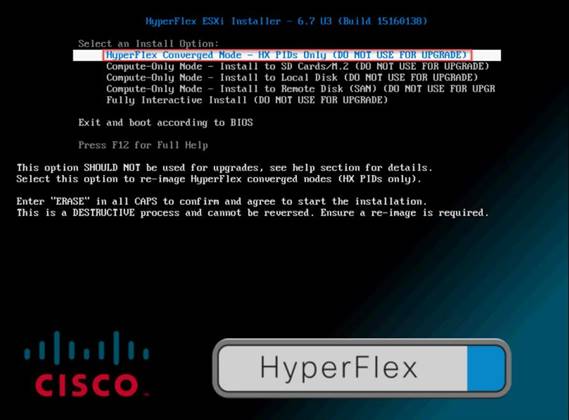
14. Enter “ERASE” in all uppercase letters, and press Enter to confirm and install ESXi.
![]()
15. (Optional) When installing Compute-Only nodes, the appropriate Compute-Only Node option for the boot location to be used should be selected. The “Fully Interactive Install” option should only be used for debugging purposes.
16. The ESXi installer will continue the installation process automatically, there may be error messages seen on screen temporarily, but they can be safely ignored. When the process is complete, the standard ESXi console screen will display as shown below:

Undo vMedia and Boot Policy Changes
When all the servers have booted from the remote vMedia file and begun their installation process, the changes to the boot policy need to be quickly undone, to prevent the servers from going into a boot loop, constantly booting from the installation ISO file. To revert the boot policy settings, follow these steps:
1. Choose Servers > Policies > root > Sub-Organizations > <<HX_ORG>> > Boot Policy HyperFlex.
2. Choose the CIMC Mounted CD/DVD entry in the Boot Order list, and click Delete.
3. Click Save Changes and click OK.
The changes made to the vMedia policy and service profile template may also be undone once the ESXi installations have all completed fully, or they may be left in place for future installation work.
The process to expand a HyperFlex cluster can be used to grow an existing HyperFlex cluster with additional converged storage nodes, or to expand an existing cluster with additional compute-only nodes to create an extended cluster. At the time of this document, Cisco Intersight cannot perform HyperFlex cluster expansions, therefore the Cisco HyperFlex installer VM must be used. The Cisco HyperFlex installer VM is deployed via a downloadable ISO image from cisco.com.
Expansion with Compute-Only Nodes
The following technical guidelines must be followed when adding compute-only nodes to a Cisco HyperFlex cluster:
· The number of compute-only nodes cannot exceed the number of HyperFlex converged nodes within a single HyperFlex cluster unless the appropriate HyperFlex Enterprise licenses have been purchased, allowing up to a 2:1 ratio of compute-only nodes to converged nodes.
· The Cisco UCS infrastructure firmware revision, which provides the firmware for Cisco UCS Manager and the Fabric Interconnects, must be maintained at the minimum version required for the HyperFlex converged nodes, or higher, at all times.
· The version of VMware ESXi installed on the compute-only nodes must be compatible with the Cisco HyperFlex version in use, and it must match the version installed on the HyperFlex converged nodes.
· While the CPU models and memory capacities between the compute-only nodes and the HyperFlex converged nodes do not have to match, configuring the nodes to have similar capacities is recommended.
· Mixing different models of compute-only nodes is allowed within the same cluster. Example: using Cisco UCS C220 M3 and Cisco UCS C240 M4 servers as compute-only nodes is allowed.
· Mixing CPU generations will require configuring VMware Enhanced vMotion Compatibility (EVC) in order to allow vMotion to work between the compute-only nodes and the converged nodes. Enabling EVC typically requires all VMs to be powered off including the HyperFlex Storage Controller VMs, therefore the HyperFlex cluster must be shut down for an outage. If it is known ahead of time that EVC will be needed, then it is easier to create the vCenter cluster object and enable EVC prior to installing HyperFlex.
· Connectivity between compute-only nodes and the HyperFlex cluster must be within the same Cisco UCS domain, and networking speeds of the additional compute-only nodes should match the speeds of the existing converged nodes. Connecting compute-only nodes from a different Cisco UCS domain is not allowed, nor is connecting standalone rack-mount servers from outside of the Cisco UCS domain allowed.
· Blade servers installed in the Cisco UCS 5108 Blade Chassis can connect through 10 GbE or 40 GbE chassis links, using the Cisco UCS 2204XP, 2208XP, or 2304 model Fabric Extenders. The Fabric Extenders, also called I/O Modules (IOMs), are typically installed in pairs, and connect the 5108 chassis to the Fabric Interconnects, which provide all the networking and management for the blades. Care must be taken not to oversubscribe and saturate the chassis links.
· Compute-only nodes can be configured to boot from SAN, local disks, or internal SD cards. No other internal storage should be present in a compute-only node. Manual configuration of the appropriate boot policy will be necessary if booting from any device other than SD cards.
· Compute-only nodes can be configured with additional vNICs or vHBAs in order to connect to supported external storage arrays via NFS, iSCSI or Fibre Channel, in the same way as HyperFlex converged nodes are allowed to do.
· Care must be taken that the addition of the compute-only nodes will not significantly impact the HyperFlex cluster by creating additional load, or by consuming too much space. Pay close attention to the space consumption and performance requirements of any net-new VMs that will run on the additional compute-only nodes, and also note the current cluster performance and space utilization. If no new VMs will be created, then the current cluster performance will not be impacted.
The Cisco HyperFlex installer VM has a wizard for Cluster Expansion with converged nodes and compute-only nodes, however the compute-only node process requires some additional manual steps to install the ESXi hypervisor on the nodes. To expand an existing HyperFlex cluster with compute-only nodes, creating an extended HyperFlex cluster, follow these steps:
1. On the HyperFlex installer webpage click the drop-down list for Expand Cluster, then click Standard Cluster.
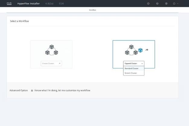
2. Enter the Cisco UCS Manager and vCenter DNS hostname or IP address, the admin usernames, and the passwords for the UCS domain where the existing and new nodes are, and the managing vCenter server of the cluster to be expanded. Optionally, you can import a JSON file that has the configuration information, except for the appropriate passwords. Click Continue.
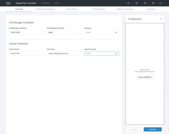
3. Choose the HX cluster to expand and enter the cluster management password, then click Continue. If the installer has been reset, or otherwise does not detect a cluster to expand, enter the HX cluster management IP address, username and password of a different cluster instead.
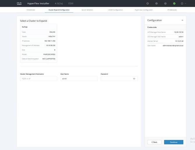
4. Choose the unassociated compute-only servers you want to add to the existing HX cluster, then click Continue.
5. On the UCSM Configuration page, all the settings should be pre-populated with the correct values for the existing cluster. The only value that is required is to create an additional IP address block for the hx-ext-mgmt IP address pool. Enter a range of IP addresses sufficient to assign to the new server(s), along with the subnet mask and gateway address, then click Continue.
6. Enter the subnet mask, gateway, DNS, and IP addresses for the Hypervisors (ESXi hosts) as well as host names, then click Continue. The IPs will be assigned through Cisco UCS Manager to the ESXi systems.
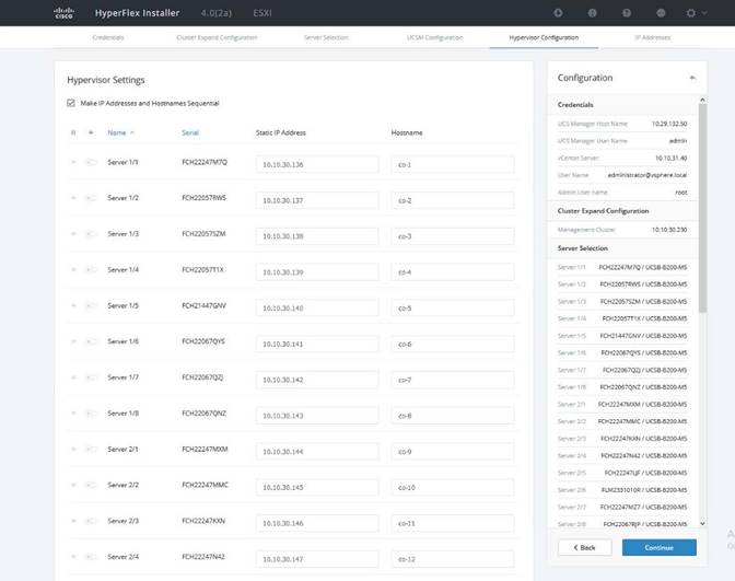
7. Enter the additional IP addresses for the Management and Data networks of the new nodes. The HyperFlex Data VLAN IP addresses are automatically assigned during an installation via Cisco Intersight, however when expanding a cluster this step must be done manually. All addresses in the Data VLAN come from the link-local subnet of 169.254.0.0/16. The third octet is derived from converting the MAC address pool prefix into a binary number. It is critical to examine the existing addresses and take note of the existing value of the third octet for the vmk1 ports of the existing servers, as the subnet mask set on the hosts is actually 255.255.255.0. Therefore, if the third octet for the new values entered is not matched to the existing servers then there will be failures and errors. The value for the fourth octet is sequentially set, starting with .1 for the overall cluster, then proceeding to .2 for the vmk1(Hypervisor) port of the first server, then .3 for the Storage Controller VM of the first server. The second server would be assigned .4 for its vmk1 port, and .5 for its Storage Controller VM. It is important to note the ending values for these assignments among the existing servers, then continue this same addressing pattern for the new servers being added. In this example, a cluster with 4 converged nodes is being expanded with a 5th compute-only node, so the vmk1 (Hypervisor) port for the new server is .10, and there is no Storage Controller VM, so no IP addresses are required for that.
8. Enter the current password that is set on the Controller VMs.
9. (Optional) At this step more servers can be added for expansion if these servers already have service profiles associated and the hypervisor is ready, by clicking on Add Compute Server or Add Converged Server and then entering the IP addresses for the storage controller management and data networks.
10. Click Start.
11. Click Continue to accept the warning that by default new compute-only nodes are configured to boot from redundant Flex-flash cards. If necessary, follow the instructions referenced to create a new local disk configuration policy and boot policy for the new compute-only nodes.
12. Validation of the configuration will now start. After validation, the installer will create the compute-only node service profiles and associate them with the selected servers. Once the service profiles are associated, the installer will move on to the UCSM Configuration step. If the hypervisor is already installed, then move ahead to step 36. If the ESXi hypervisor has not been previously installed on the compute-only nodes, the installer will stop with errors as shown below due to the missing hypervisor. Continue to step 13 and do not click Retry UCSM Configuration until the hypervisor has been installed.
To install ESXi onto the new compute-only nodes, follow these steps:
1. In Cisco UCS Manager, click Servers.
2. Expand Servers > Service Profiles > root > Sub-Organizations > <<HX_ORG>>.
3. Each new compute-only node will have a new service profile, for example: chassis-1_blade-1. Right-click the new service profile and click KVM Console. The remote KVM console will open in a new browser tab. Accept any SSL errors or alerts, then click the link to launch the KVM console.
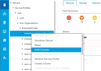
4. Repeat step 15 for each new service profile, that is associated with the new compute-only nodes.
5. In the remote KVM tab, click the Virtual Media button in the top right-hand corner of the screen, then click Activate Virtual Devices.
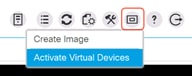
6. In the remote KVM tab, click Virtual Media, then click the CD/DVD option.
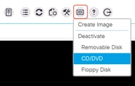
7. Click Choose File, browse for the Cisco custom ESXi ISO installer file for HyperFlex nodes, and click Open.
8. Click Map Drive.
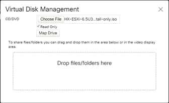
9. Repeat steps 1-8 for all the new compute-only nodes.
10. In the remote KVM tab, click the Server Actions button in the top right-hand corner of the screen, the click Reset.
11. Click OK.
12. Choose the Power Cycle option, then click OK.
13. Click OK.
14. Observe the server going through the POST process until the following screen is seen. When it appears, press the F6 key to enter into the boot device selection menu.
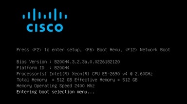
15. Choose Cisco vKVM-mapped vDVD1.22, then press Enter.
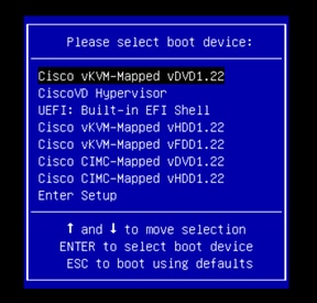
16. The server will boot from the remote KVM mapped ESXi ISO installer and display the following screen:
17. Choose the appropriate installation option for the compute-only node you are installing, either installing to SD cards, local disks, or booting from SAN, then press Enter.
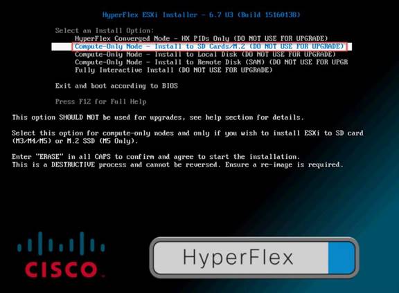
18. Type “ERASE” in all capital letters and press Enter to accept the warning and continue the installation.
19. The ESXi installer will now automatically perform the installation to the boot media. As you watch the process, some errors may be seen, but they can be ignored. Once the new server has completed the ESXi installation, it will be waiting at the console status screen shown below.
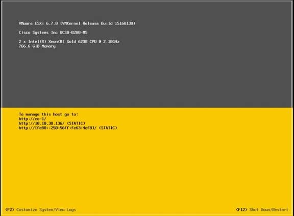
20. Repeat steps 1-19 for all the additional new compute-only nodes being added to the HX cluster.
21. When all the new nodes have finished their fresh ESXi installations, return to the HX installer, where the error in step 12 was seen. Click Retry UCSM Configuration.
22. The HX installer will now proceed to complete the deployment and perform all the steps listed at the top of the screen along with their status.
23. When the expansion is completed, a summary screen showing the status of the expanded cluster and the expansion operation is shown.
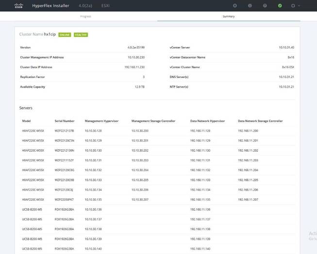
After the install has completed, the new compute-only node is added to the cluster and it will have mounted the existing HyperFlex datastores, however the new node still requires some post installation steps in order to be consistent with the configuration of the existing nodes. For example, the new compute-only node will not have a vMotion vmkernel interface, and it may not have all of the guest VM networks configured. The easiest method to make the changes is to use the post_install script, choosing option 2 to configure an Expanded cluster, or the configuration can be done manually.
A list of additional configuration steps necessary includes:
· Disable SSH warning
· Creation of the guest VM port groups
· Creation of the vMotion vmkernel port
· Syslog Server Configuration
![]() Note: If at a later time the post_install script needs to be run against a specific HX cluster, the cluster can be specified by using the --cluster-ip switch and entering the cluster’s management IP address.
Note: If at a later time the post_install script needs to be run against a specific HX cluster, the cluster can be specified by using the --cluster-ip switch and entering the cluster’s management IP address.
To validate the configuration, vMotion a VM to the new compute-only node. You can validate that your VM is now running on the compute-only node through the Summary tab of the VM.
HyperFlex Connect
HyperFlex Connect is the new, easy to use, and powerful primary management tool for HyperFlex clusters. HyperFlex Connect is an HTML5 web-based GUI tool which runs on all of the HX nodes and is accessible via the cluster management IP address.
Local Access
Logging into HyperFlex Connect can be done using pre-defined local accounts. The default predefined administrative account is named “admin”. The password for the default admin account is set during the cluster creation as the cluster password. Using local access is only recommended when vCenter direct or SSO credentials are not available.
Role-Based Access Control
HyperFlex Connect provides Role-Based Access Control (RBAC) via integrated authentication with the vCenter Server managing the HyperFlex cluster. You can have two levels of rights and permissions within the HyperFlex cluster:
· Administrator: Users with administrator rights in the managing vCenter server will have read and modify rights within HyperFlex Connect. These users can make changes to the cluster settings and configuration.
· Read-Only: Users with read-only rights in the managing vCenter server will have read rights within HyperFlex Connect. These users cannot make changes to the cluster settings and configuration.
Users can log into HyperFlex Connect using direct vCenter credentials, for example, administrator@vsphere.local, or using vCenter Single Sign-On (SSO) credentials such as an Active Directory user, for example, domain\user. Creation and management of RBAC users and rights must be done via the vCenter Web Client or vCenter 6.5 HTML5 vSphere Client.
To manage the HyperFlex cluster using HyperFlex Connect, follow these steps:
1. Using a web browser, open the HyperFlex cluster’s management IP address via HTTPS.
2. Enter a local credential, such as local/root, or a vCenter RBAC credential for the username, and the corresponding password.
3. Click Login.
4. The Dashboard view will be shown after a successful login.
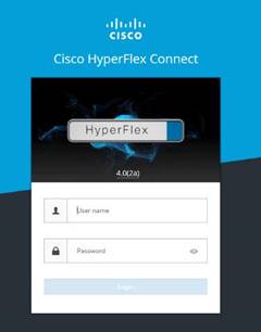
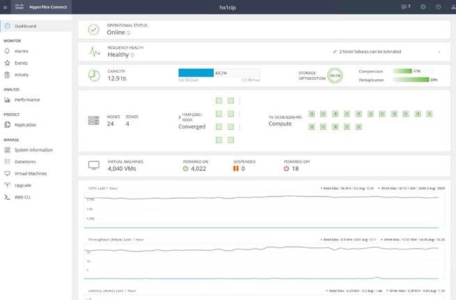
Dashboard
From the Dashboard view, several elements are presented:
· Cluster operational status, overall cluster health, and the cluster’s current node failure tolerance.
· Cluster storage capacity, used and free space, compression and deduplication savings, and overall cluster storage optimization statistics.
· Cluster size and individual node health.
· Cluster IOPs, storage throughput, and latency for the past 1 hour.
Monitor
HyperFlex Connect provides for additional monitoring capabilities, including:
· Alarms: Cluster alarms can be viewed, acknowledged and reset.
· Event Log: The cluster event log can be viewed, specific events can be filtered for, and the log can be exported.
· Activity Log: Recent job activity, such as ReadyClones can be viewed and the status can be monitored.
Analyze
The historical and current performance of the HyperFlex cluster can be analyzed via the built-in performance charts. The default view shows read and write IOPs, bandwidth, and latency over the past 1 hour for the entire cluster. Views can be customized to see individual nodes or datastores, and change the timeframe shown in the charts.
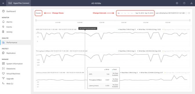
Protect
HyperFlex Connect is used as the management tool for all configuration of HyperFlex Data Protection features, including VM replication and data-at-rest encryption.
Manage
HyperFlex Connect presents several views and elements for managing the HyperFlex cluster:
· System Information: Presents a detailed view of the cluster configuration, software revisions, hosts, disks, and cluster uptime. Support bundles can be generated to be shared with Cisco TAC when technical support is needed. Views of the individual nodes and the individual disks are available. In these views, nodes can be placed into HX Maintenance Mode, and self-encrypting disks can be securely erased.
· Datastores: Presents the datastores present in the cluster, and allows for datastores to be created, mounted, unmounted, edited or deleted, as described earlier in this document as part of the cluster setup.
· Virtual Machines: Presents the VMs present in the cluster, and allows for the VMs to be powered on or off, cloned via HX ReadyClone, Snapshots taken, and protected via native replication.
· Upgrade: One-click upgrades to the HXDP software, ESXi host software and Cisco UCS firmware can be initiated from this view.
· Web CLI: A web-based interface, from which CLI commands can be issued and their output seen, as opposed to directly logging into the SCVMs via SSH.
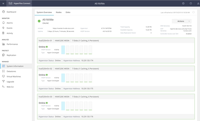
Cisco Intersight Cloud-Based Management
Cisco Intersight management is enabled via embedded code running on the Cisco UCS Fabric Interconnects, and in the Cisco HyperFlex software, known as device connectors. To enable Intersight management, the device connectors are registered online at the Cisco Intersight website, https://intersight.com when logged into the website with a valid cisco.com account used to manage your environments. Cisco Intersight can be used to manage and monitor HyperFlex clusters and UCS domains with the following software revisions:
· Cisco UCS Manager and Infrastructure Firmware version 3.2 and later
· Cisco HyperFlex software version 2.5(1a) or later
The Cisco UCS Fabric Interconnects, and the Cisco HyperFlex nodes must have DNS lookup capabilities and access to the internet. If direct access to the internet is not available, the systems can be configured to connect via an HTTPS proxy server.
Cisco Intersight Licensing
Cisco Intersight is offered in two editions; a Base license which is free to use, and offers a large variety of monitoring, inventory and reporting features, and an added cost Essentials license, which adds advanced monitoring, server policy and profile configuration, firmware management, virtual KVM features, and more. New features and capabilities will be added to the different licensing tiers over time. A 90-day trial of the Essentials license is available for use as an evaluation period.
To configure Cisco Intersight licensing, follow these steps:
1. Using a web browser, log into the Cisco Intersight webpage at https://intersight.com (you must have a valid cisco.com CCO account).
2. In the Dashboards view, click the gear shaped icon in the upper right-hand corner, then click Licensing.
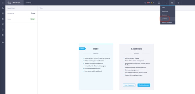
3. Click Start Evaluation to begin a 90-day Essentials license trial or click Register License.
Cisco Intersight HyperFlex Management
To connect Cisco Intersight to the Cisco HyperFlex cluster(s), and the Cisco UCS Domain(s) in your environments, follow the steps in this section.
Connect Cisco UCS Manager
To connect to Cisco UCS Manager (UCSM), follow these steps:
1. Using a web browser, log into the Cisco UCS Manager webpage.
2. From a second browser window or tab, log into the Cisco Intersight webpage at https://intersight.com (you must have a valid cisco.com CCO account).

3. Click Devices.
4. Click Claim A New Device.
5. In Cisco UCS Manager, click Admin.
6. In the Admin tree, click Device Connector.
7. If necessary, click HTTPS Proxy Settings and then click Manual. Enter the Proxy server IP address or DNS hostname, the TCP port, enable authentication then enter a username and password if necessary, then click Save.
8. If desired, the Access Mode for Cisco Intersight can be set to Read-only, or management can be disabled from this screen.
9. In the main UCS Manager screen, you will see a Device ID and a Claim Code for this Cisco UCS Domain. Copy these two codes by clicking on the clipboard icons and pasting them to the Device ID and Claim Code fields in the Cisco Intersight “Claim A New Device” window, then click Claim.
The Cisco UCS Domain will now show the system as Claimed in the Device Connector screen.
Connecting Cisco HyperFlex Clusters
To connect Cisco HyperFlex Clusters, follow these steps:
1. Use a web browser to open the HX Connect webpage at the cluster’s management IP address, for example: https://10.29.132.182/
2. Enter a local credential or a vCenter RBAC credential for the username and the corresponding password.
3. Click Login.
4. From a second browser window or tab, log into the Cisco Intersight webpage at https://intersight.com (you must have a valid cisco.com CCO account).
5. In the left-hand navigation buttons, click Devices.
6. Click Claim A New Device.
7. In the HyperFlex Connect Dashboard page, click Edit Settings in the top right-hand corner, then click Device Connector.
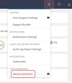
8. If necessary, to modify the Proxy settings, click the Settings button, and click the Proxy Settings link on the left-hand side. Enable the Proxy configuration button, then enter the Proxy server IP address or DNS hostname, the TCP port, enable authentication then enter a username and password if necessary, then click Save.
9. If desired, the Access Mode for Cisco Intersight can be set to Read-only, or management can be disabled from this screen.
10. In the HyperFlex Connect screen, a Device ID and a Claim Code for this HyperFlex cluster will be shown. Copy these two codes by clicking on the clipboard icons and pasting them to the Device ID and Claim Code fields in the Cisco Intersight “Claim A New Device” window, then click Claim.
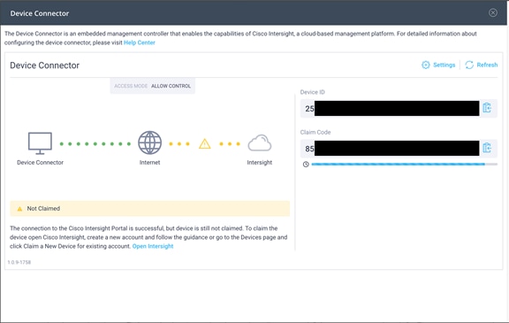
11. The Cisco HyperFlex Cluster will now show the system as Claimed in the Device Connector screen.
Dashboard
The Cisco Intersight Dashboard provides a single screen overview of all connected Cisco UCS Domains, the servers within those domains, the HyperFlex Clusters running in the domains, along with their health statuses, storage utilization, port counts, and more. Elements on the screen are clickable and will drill down into other sections of the page to view further details.

Servers
The Servers screen provides details of all the individual servers within the connected and managed UCS domains.
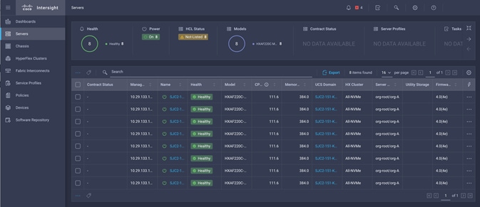
HyperFlex Clusters
The HyperFlex Clusters screen provides details of all the HyperFlex clusters that are connected and managed by Cisco Intersight. By clicking the ellipses (…) the HyperFlex Connect GUI for the clusters can be directly connected to in another browser window or tab.
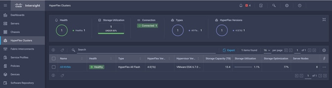
Fabric Interconnects
The Fabric Interconnects screen provides details of all the UCS domains that are connected and managed by Cisco Intersight. By clicking the ellipses (…) the Cisco UCS Manager webpage for the domain can be directly connected to in another browser window or tab, or a session can be opened to the CLI of the Fabric Interconnect.
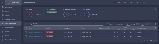
Profiles and Policies
Cisco Intersight Service Profiles and Policies pages are only available with Intersight Essentials licensing, except for configuring a Cisco HyperFlex Cluster Profile as outlined earlier in this document.
Management Best Practices
In this section, various best practices and guidelines are given for management and ongoing use of the Cisco HyperFlex system. These guidelines and recommendations apply only to the software versions upon which this document is based, listed in Software Components.
ReadyClones
For the best possible performance and functionality of the virtual machines that will be created using the HyperFlex ReadyClone feature, the following guidelines for preparation of the base VMs to be cloned should be followed:
· Base VMs must be stored in a HyperFlex datastore.
· All virtual disks of the base VM must be stored in the same HyperFlex datastore.
· Base VMs can only have HyperFlex native snapshots, no VMware redo-log based snapshots can be present.
· For very high IO workloads with many clone VMs leveraging the same base image, it might be necessary to use multiple copies of the same base image for groups of clones. Doing so prevents referencing the same blocks across all clones and could yield an increase in performance. This step is typically not required for most use cases and workload types.
Snapshots
HyperFlex native snapshots are high performance snapshots that are space-efficient, crash-consistent, and application consistent, taken by the HyperFlex Distributed Filesystem, rather than using VMware redo-log based snapshots. For the best possible performance and functionality of HyperFlex native snapshots, the following guidelines should be followed:
· Make sure that the first snapshot taken of a guest VM is a HyperFlex native snapshot, by using the “Cisco HX Data Platform” menu item in the vSphere Web Client, and choosing Snapshot Now or Schedule Snapshot. Failure to do so reverts to VMware redo-log based snapshots.
· A Sentinel snapshot becomes a base snapshot that all future snapshots are added to and prevents the VM from reverting to VMware redo-log based snapshots. Failure to do so can cause performance degradation when taking snapshots later, while the VM is performing large amounts of storage IO.
· Additional snapshots can be taken via the “Cisco HX Data Platform” menu, or the standard vSphere client snapshot menu. As long as the initial snapshot was a HyperFlex native snapshot, each additional snapshot is also considered to be a HyperFlex native snapshot.
· Do not delete the Sentinel snapshot unless you are deleting all the snapshots entirely.
· Do not revert the VM to the Sentinel snapshot.
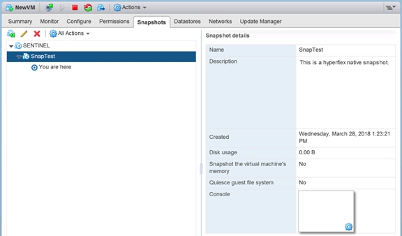
· If large numbers of scheduled snapshots need to be taken, distribute the time of the snapshots taken by placing the VMs into multiple folders or resource pools. For example, schedule two resource groups, each with several VMs, to take snapshots separated by 15-minute intervals in the scheduler window. Snapshots will be processed in batches of 8 at a time, until the scheduled task is completed.
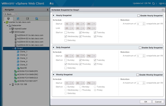
Storage vMotion
The Cisco HyperFlex Distributed Filesystem can create multiple datastores for storage of virtual machines. While there can be multiple datastores for logical separation, all of the files are located within a single distributed filesystem. As such, performing a storage vMotion of virtual machine disk files has little value in the HyperFlex system. Furthermore, storage vMotion can create additional filesystem consumption and generate additional unnecessary metadata within the filesystem, which must later be cleaned up via the filesystem’s internal cleaner process.
![]() Note: It is recommended to not perform a storage vMotion of a guest VM between datastores within the same HyperFlex cluster. Storage vMotion between different HyperFlex clusters, or between HyperFlex and non-HyperFlex datastores are permitted.
Note: It is recommended to not perform a storage vMotion of a guest VM between datastores within the same HyperFlex cluster. Storage vMotion between different HyperFlex clusters, or between HyperFlex and non-HyperFlex datastores are permitted.
Virtual Disk Placement
HyperFlex clusters can create multiple datastores for logical separation of virtual machine storage, yet the files are all stored in the same underlying distributed filesystem. The only difference between one datastore and another are their names and their configured sizes. Due to this, there is no compelling reason for a virtual machine’s virtual disk files to be stored on a particular datastore versus another.
![]() Note: All of the virtual disks that make up a single virtual machine must be placed in the same datastore. Spreading the virtual disks across multiple datastores provides no benefit, can cause ReadyClone and Snapshot errors, and lead to degraded performance in stretched clusters.
Note: All of the virtual disks that make up a single virtual machine must be placed in the same datastore. Spreading the virtual disks across multiple datastores provides no benefit, can cause ReadyClone and Snapshot errors, and lead to degraded performance in stretched clusters.
Maintenance Mode
Cisco HyperFlex clusters which have been originally installed using HXDP version 4.0(1b) or later no longer require the use of “HX Maintenance Mode” in order to evacuate the converged nodes for reboots, patches or other work. Use of the standard enter/exit maintenance mode available in the vCenter web client or HTML5 web client is sufficient. Clusters which are upgraded from earlier revisions to version 4.0(1b) or later can also use standard vSphere maintenance mode, after undergoing a process to remove vSphere ESX Agent Manager (EAM) components and settings that are no longer required. These instructions are available upon request from your Cisco sales team or technical support contacts.
This section provides a list of items that should be reviewed after the HyperFlex system has been deployed and configured. The goal of this section is to verify the configuration and functionality of the solution and ensure that the configuration supports core availability requirements.
Post Install Checklist
The following tests are critical to functionality of the solution, and should be verified before deploying for production:
1. Verify the expected number of converged storage nodes and compute-only nodes are members of the HyperFlex cluster in the vSphere Web Client plugin manage cluster screen.
2. Verify the expected cluster capacity is seen in the HX Connect Dashboard summary screen.
3. Create a test virtual machine that accesses the HyperFlex datastore and is able to perform read/write operations.
4. Perform a virtual machine migration (vMotion) of the test virtual machine to a different host on the cluster.
5. During the vMotion of the virtual machine, make sure the test virtual machine can perform a continuous ping to its default gateway and to check if the network connectivity is maintained during and after the migration.
Verify Redundancy
The following redundancy checks can be performed to verify the robustness of the system. Network traffic, such as a continuous ping from VM to VM, or from vCenter to the ESXi hosts should not show significant failures (one or two ping drops might be observed at times). Also, all of the HyperFlex datastores must remain mounted and accessible from all the hosts at all times.
1. Administratively disable one of the server ports on Fabric Interconnect A which is connected to one of the HyperFlex converged storage hosts. The ESXi virtual switch uplinks for fabric A should now show as failed, and the standby uplinks on fabric B will be in use for the management and vMotion virtual switches. Upon administratively re-enabling the port, the uplinks in use should return to normal.
2. Administratively disable one of the server ports on Fabric Interconnect B which is connected to one of the HyperFlex converged storage hosts. The ESXi virtual switch uplinks for fabric B should now show as failed, and the standby uplinks on fabric A will be in use for the storage virtual switch. Upon administratively re-enabling the port, the uplinks in use should return to normal.
3. Place a representative load of guest virtual machines on the system. Put one of the ESXi hosts in maintenance mode, using the HyperFlex HX maintenance mode option. All the VMs running on that host should be migrated via vMotion to other active hosts through vSphere DRS, except for the storage platform controller VM, which will be powered off. No guest VMs should lose any network or storage accessibility during or after the migration. This test assumes that enough RAM is available on the remaining ESXi hosts to accommodate VMs from the host put in maintenance mode. The HyperFlex cluster will show in an unhealthy state in the HX Connect Dashboard.
4. Reboot the host that is in maintenance mode and exit it from maintenance mode after the reboot. The storage platform controller will automatically start when the host exits maintenance mode. The HyperFlex cluster will show as healthy in the HX Connect Dashboard after a brief time to restart the services on that node. vSphere DRS should rebalance the VM distribution across the cluster over time.
![]() Note: Many vCenter alerts automatically clear when the fault has been resolved. Once the cluster health is verified, some alerts may need to be manually cleared.
Note: Many vCenter alerts automatically clear when the fault has been resolved. Once the cluster health is verified, some alerts may need to be manually cleared.
5. Reboot one of the two Cisco UCS Fabric Interconnects while traffic is being sent and received on the storage datastores and the network. The reboot should not affect the proper operation of storage access and network traffic generated by the VMs. Numerous faults and errors will be noted in Cisco UCS Manager, but all will be cleared after the FI comes back online.
Software Infrastructure Configuration
This section details how to configure the software infrastructure components that comprise this solution.
Install and configure the infrastructure virtual machines by following the process provided in Table 46.
Table 46 Test Infrastructure Virtual Machine Configuration
| Configuration |
Citrix Virtual Desktops Controllers Virtual Machines |
Citrix Provisioning Services Servers Virtual Machines |
| Operating System |
Microsoft Windows Server 2019 |
Microsoft Windows Server 2019 |
| Virtual CPU amount |
6 |
8 |
| Memory amount |
8 GB |
12 GB |
| Network |
VMNIC |
Network |
| Disk-1 (OS) size and location |
40 GB |
Disk-1 (OS) size and location |
| Disk-2 size and location |
500GB |
Disk-2 (Data) Paravirtual SCSI adapter with ReFS format |
| Configuration |
Microsoft Active Directory DC’s Virtual Machines |
Citrix Profile Servers Virtual Machines |
| Operating system |
Microsoft Windows Server 2019 |
Operating system |
| Virtual CPU amount |
4 |
|
| Memory amount |
4 GB |
|
| Network |
VMNIC |
|
| Disk size and location |
40 GB |
|
| Configuration |
Microsoft SQL Server Virtual Machine |
Citrix StoreFront Virtual Machine |
| Operating system |
Microsoft Windows Server 2019 |
Microsoft Windows Server 2019 |
| Virtual CPU amount |
8 |
4 |
| Memory amount |
16 GB |
8 GB |
| Network |
VMNIC |
Network |
| Disk-1 (OS) size and location |
40 GB |
Disk-1 (OS) size and location |
| Disk-2 size and location |
200 GB Infra-DS volume |
Disk-2 size and location |
| Configuration |
Citrix License Server Virtual Machine |
NetScaler VPX Appliance Virtual Machine |
| Operating system |
Microsoft Windows Server 2019 |
NS11.1 52.13.nc |
| Virtual CPU amount |
4 |
2 |
| Memory amount |
4 GB |
2 GB |
| Network |
VMNIC |
Network |
| Disk size and location |
40 GB |
20 GB |
Prepare the Master Images
This section details how to create the golden (or master) images for the environment. virtual machines for the master images must first be installed with the software components needed to build the golden images. For this CVD, the images contain the basics needed to run the Login VSI workload.
To prepare the master virtual machines for the Hosted Virtual Desktops (HVDs) and Hosted Shared Desktops (HSDs), there are three major steps to complete when the base virtual machine has been created:
· Installing OS
· Installing application software
· Installing the Virtual Delivery Agents (VDAs)
The master image HVD and HSD virtual machines were configured as listed in Table 47.
Table 47 HVD and HSD Configurations
| Configuration |
HVDI Virtual Machines |
HSD Virtual Machines |
| Operating system |
Microsoft Windows 10 64-bit |
Microsoft Windows Server 2019 |
| Virtual CPU amount |
2 |
8 |
| Memory amount |
4.0 GB (reserved) |
24 GB (reserved) |
| Network |
VMNIC vm-network |
VMNIC vm-network |
| Citrix PVS vDisk size and location |
24 GB
|
40 GB
|
| Citrix PVS write cache Disk size |
6 GB |
24 GB |
| Additional software used for testing |
Microsoft Office 2016 Login VSI 4.1.32 (Knowledge Worker Workload) |
Microsoft Office 2016 Login VSI 4.1.32 (Knowledge Worker Workload) |
Install and Configure Citrix Desktop Delivery Controller, Citrix Licensing, and StoreFront
This section details the installation of the core components of the Citrix Virtual Apps and Desktops 1912 LTSR system. This CVD provides the process to install two Desktop Delivery Controllers to support hosted shared desktops (HSD), non-persistent virtual desktops (VDI), and persistent virtual desktops (VDI).
The process of installing the Desktop Delivery Controller also installs other key Citrix Desktop software components, including Studio, which is used to create and manage infrastructure components, and Director, which is used to monitor performance and troubleshoot problems.
Install Citrix License Server
To install the Citrix License Server, follow these steps:
1. To begin the installation, connect to the first Citrix License server and launch the installer from the Citrix Virtual Apps and Desktops 1912 LTSR ISO.
2. Click Start.

3. Click “Extend Deployment – Citrix License Server.”

4. Read the Citrix License Agreement.
5. If acceptable, indicate your acceptance of the license by selecting the “I have read, understand, and accept the terms of the license agreement” radio button.
6. Click Next.
7. Click Next.
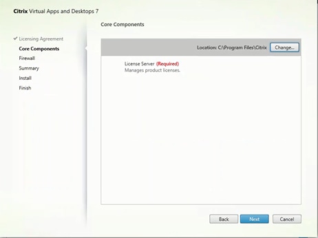
8. Choose the default ports and automatically configured firewall rules.
9. Click Next.
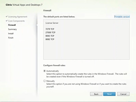
10. Click Install.
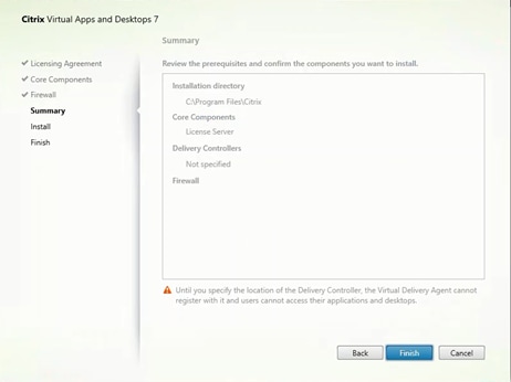
11. Click Finish to complete the installation.
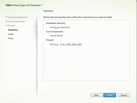
Install Citrix Licenses
To install the Citrix Licenses, follow these steps:
1. Copy the license files to the default location (C:\Program Files (x86)\Citrix\Licensing\ MyFiles) on the license server.
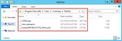
2. Restart the server or Citrix licensing services so that the licenses are activated.
3. Run the application Citrix License Administration Console.
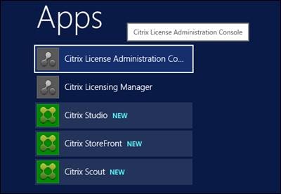
4. Confirm that the license files have been read and enabled correctly.
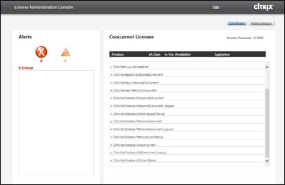
Install Citrix Desktop Broker/Studio
To install Citrix Desktop, follow these steps:
1. Connect to the first Citrix VDI server and launch the installer from the Citrix Desktop 1912 LTSR ISO.
2. Click Start.

The installation wizard presents a menu with three subsections.
3. Click “Get Started - Delivery Controller.”
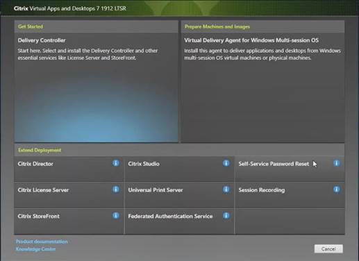
4. Read the Citrix License Agreement and if acceptable, indicate your acceptance of the license by selecting the “I have read, understand, and accept the terms of the license agreement” radio button.
5. Click Next.

6. Choose the components to be installed on the first Delivery Controller Server:
a. Delivery Controller
b. Studio
c. Director
7. Click Next.
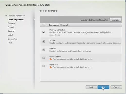
![]() Note: Dedicated StoreFront and License servers should be implemented for large-scale deployments.
Note: Dedicated StoreFront and License servers should be implemented for large-scale deployments.
8. Since a SQL Server will be used to Store the Database, leave “Install Microsoft SQL Server 2012 SP1 Express” unchecked.
9. Click Next.
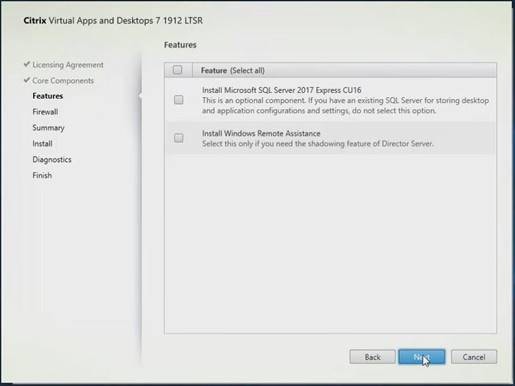
10. Choose the default ports and automatically configured firewall rules.
11. Click Next.
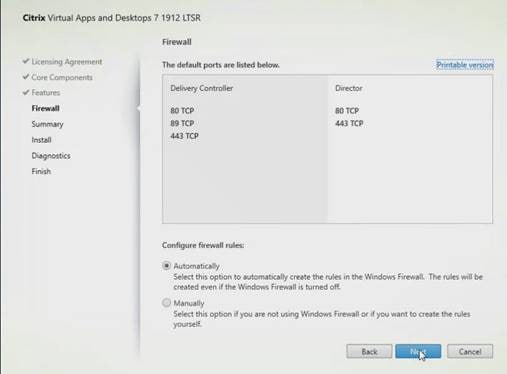
12. Click Install.
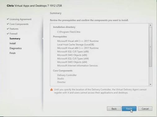
13. (Optional) Click the Call Home participation.
14. Click Next.
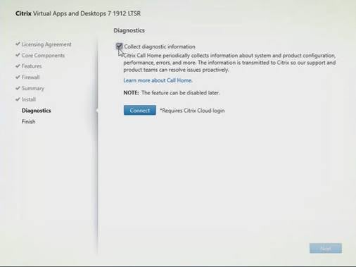
15. Click Finish to complete the installation.
16. (Optional) Check Launch Studio to launch Citrix Studio Console.
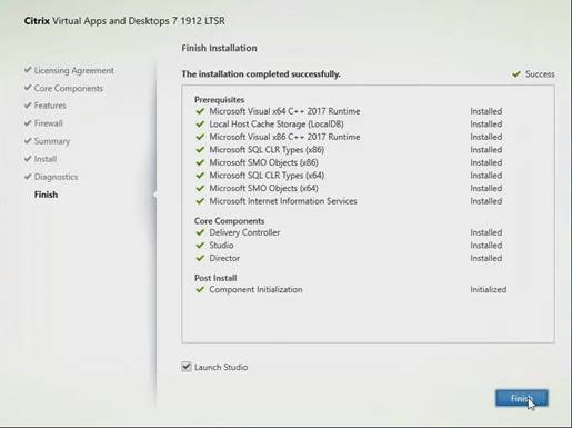
Configure the Citrix VDI Site
Citrix Studio is a management console that allows you to create and manage infrastructure and resources to deliver desktops and applications. Replacing Desktop Studio from earlier releases, it provides wizards to set up your environment, create workloads to host applications and desktops, and assign applications and desktops to users.
Citrix Studio launches automatically after the Citrix VDI Delivery Controller installation, or if necessary, it can be launched manually. Citrix Studio is used to create a Site, which is the core Citrix VDI environment consisting of the Delivery Controller and the Database.
To configure Citrix VDI, follow these steps:
1. From Citrix Studio, click Deliver applications and desktops to your users.
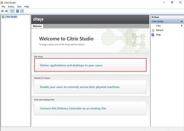
2. Choose the “A fully configured, production-ready Site” radio button.
3. Enter a site name.
4. Click Next.
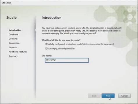
5. Provide the Database Server Locations for each data type and click Next.
6. For an AlwaysOn Availability Group, use the group’s listener DNS name.
7. Provide the FQDN of the license server.
8. Click Connect to validate and retrieve any licenses from the server.
![]() Note: If no licenses are available, you can use the 30-day free trial or activate a license file.
Note: If no licenses are available, you can use the 30-day free trial or activate a license file.
9. Choose the appropriate product edition using the license radio button.
10. Click Next.
11. Choose the Connection type of ‘Microsoft System Center Virtual Machine Manager’.
12. Enter the Connection Address to the SCVMM Server.
13. Enter the username (in username@domain format) for the vCenter account.
14. Provide the password for the Domain Admin account.
15. Provide a connection name.
16. Choose the Studio tools radio button.
17. Click Next.
18. Choose HyperFlex Cluster that will be used by this connection.
19. Check Studio Tools radio button required to support desktop provisioning task by this connection.
20. Click Next.
21. Make Storage selection to be used by this connection.
22. Click Next.
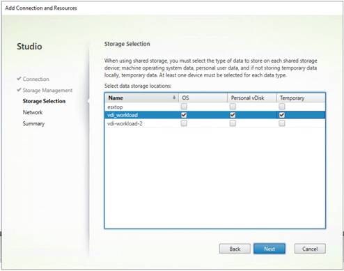
23. Make Network selection to be used by this connection.
24. Click Next.
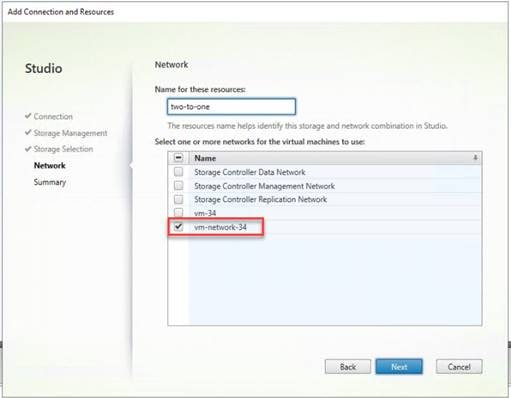
25. Choose Additional features.
26. Click Next.
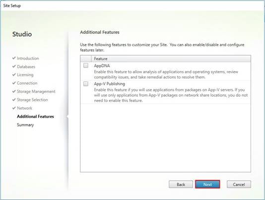
27. Review Site configuration Summary and click Finish.
Configure the Citrix VDI Site Administrators
To configure the Citrix VDI site administrators, follow these steps:
1. Connect to the Citrix VDI server and open Citrix Studio Management console.
2. From the Configuration menu, right-click Administrator and choose Create Administrator from the drop-down list.
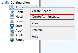
3. Choose/Create appropriate scope and click Next.
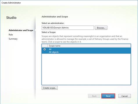
4. Choose an appropriate Role.
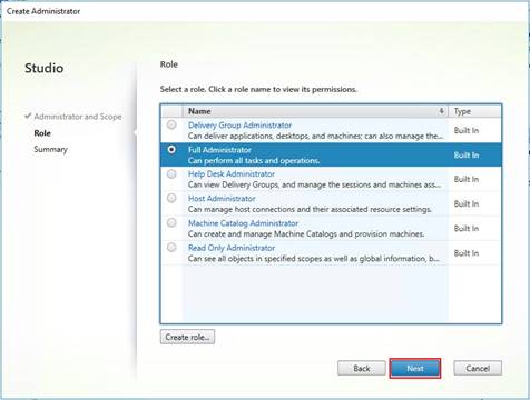
5. Review the Summary, check Enable administrator, and click Finish.
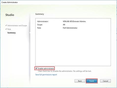
Configure Additional Desktop Controller
After the first controller is completely configured and the Site is operational, you can add additional controllers.
![]() Note: In this CVD, we created two Delivery Controllers.
Note: In this CVD, we created two Delivery Controllers.
To configure additional Citrix Desktop controllers, follow these steps:
1. To begin the installation of the second Delivery Controller, connect to the second Citrix VDI server and launch the installer from the Citrix Virtual Apps and Desktops ISO.
2. Click Start.
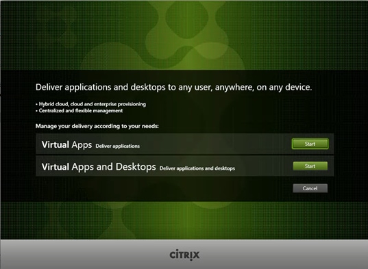
3. Click Delivery Controller.

4. Repeat these steps used to install the first Delivery Controller, including the step of importing an SSL certificate for HTTPS between the controller and VCenter.
5. Review the Summary configuration.
6. Click Install.
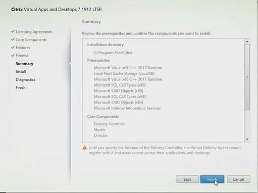
7. (Optional) Click the “Collect diagnostic information.”
8. Click Next.
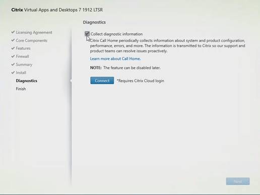
9. Verify the components installed successfully.
10. Click Finish.

Add the Second Delivery Controller to the Citrix Desktop Site
To add the second Delivery Controller to the Citrix Desktop Site, follow these steps:
1. In Desktop Studio click Connect this Delivery Controller to an existing Site.
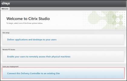
2. Enter the FQDN of the first delivery controller.
3. Click OK.
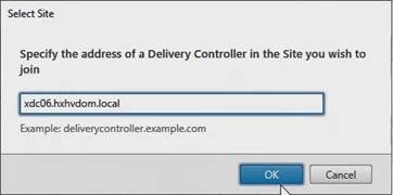
4. Click Yes to allow the database to be updated with this controller’s information automatically.
5. When complete, test the site configuration and verify the Delivery Controller has been added to the list of Controllers.
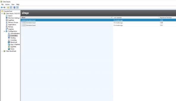
Install and Configure StoreFront
Citrix StoreFront stores aggregate desktops and applications from Citrix VDI sites, making resources readily available to users.
![]() Note: In this CVD, we created two StoreFront servers on dedicated virtual machines.
Note: In this CVD, we created two StoreFront servers on dedicated virtual machines.
To install and configure StoreFront, follow these steps:
1. To begin the installation of the StoreFront, connect to the first StoreFront server and launch the installer from the Citrix Desktop 1912 LTSR ISO.
2. Click Start.
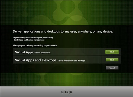
3. Click Extend Deployment Citrix StoreFront.

4. If acceptable, indicate your acceptance of the license by clicking “I have read, understand, and accept the terms of the license agreement”.
5. Click Next.
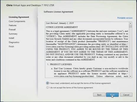
6. Choose Storefront and click Next.
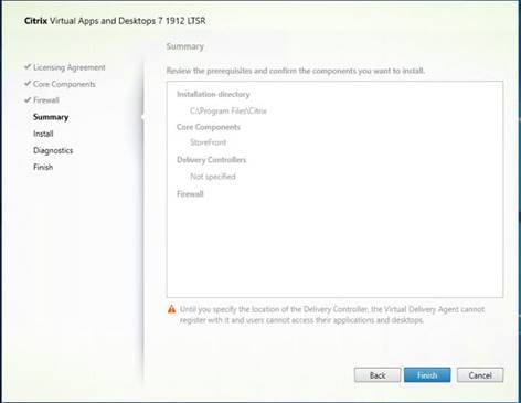
7. Choose the default ports and automatically configured firewall rules.
8. Click Next.
9. Click Install.
10. (Optional) Click “Collect diagnostic information.”
11. Click Next.
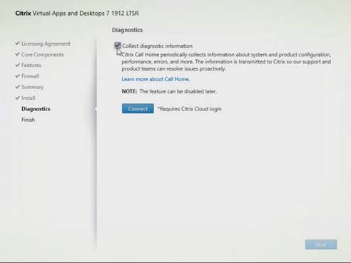
12. Click Finish.

13. Click Create a new deployment.
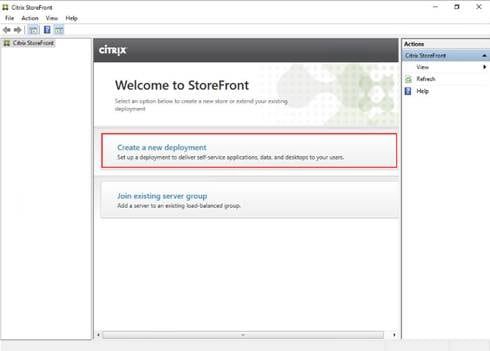
14. Specify the URL of the StoreFront server and click Next.
![]() Note: For a multiple server deployment use the load balancing environment in the Base URL box.
Note: For a multiple server deployment use the load balancing environment in the Base URL box.
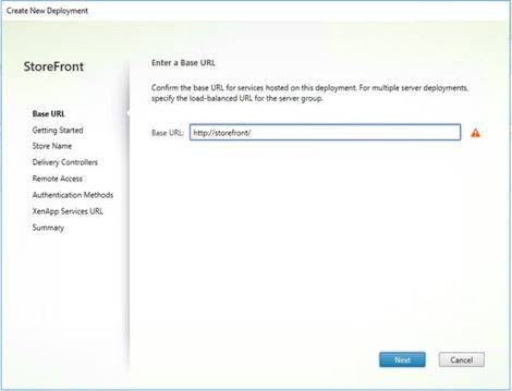
15. Click Next.
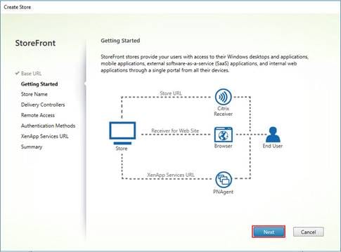
16. Specify a name for your store and click Next.
17. Add the required Delivery Controllers to the store and click Next.
18. Specify how connecting users can access the resources, in this environment only local users on the internal network are able to access the store and click Next.
19. On the “Authentication Methods” page, choose the methods your users will use to authenticate to the store and click Next. You can choose from the following methods as shown below:
20. Username and password: Users enter their credentials and are authenticated when they access their stores.
21. Domain pass-through: Users authenticate to their domain-joined Windows computers and their credentials are used to log them on automatically when they access their stores.
22. Configure the XenApp Service URL for users who use PNAgent to access the applications and desktops and click Create.
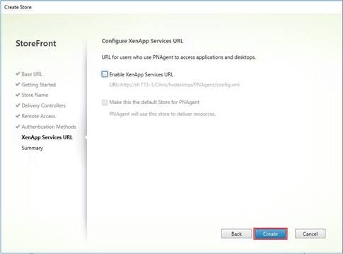
23. After creating the store click Finish.
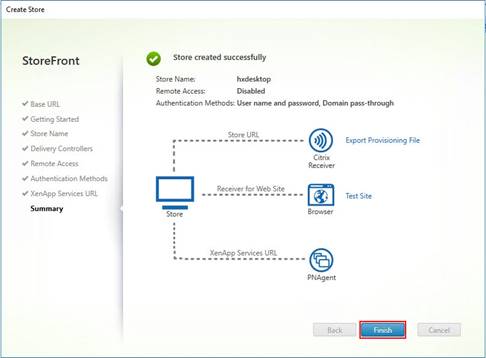
Additional StoreFront Configuration
After the first StoreFront server is completely configured and the Store is operational, you can add additional servers.
To configure additional StoreFront server, follow these steps:
1. To begin the installation of the second StoreFront, connect to the second StoreFront server and launch the installer from the Citrix VDI ISO.
2. Click Start.

3. Click Extended Deployment Citrix StoreFront.
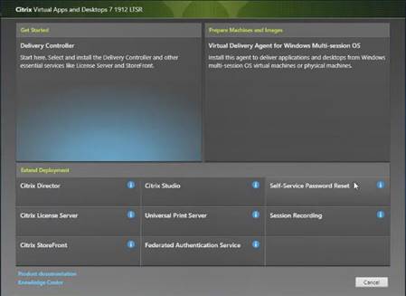
4. Repeat the same steps used to install the first StoreFront.
5. Review the Summary configuration.
6. Click Install.
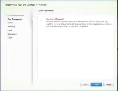
7. (Optional) Click “Collect diagnostic information.”
8. Click Next.

9. Check “Open the StoreFront Management Console."
10. Click Finish.
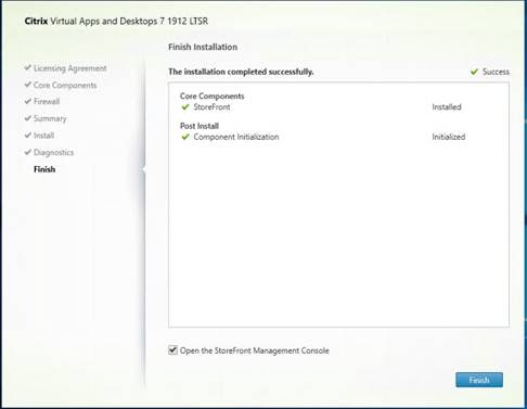
To configure the second StoreFront if used, follow these steps:
1. From the StoreFront Console on the second server choose “Join existing server group.”
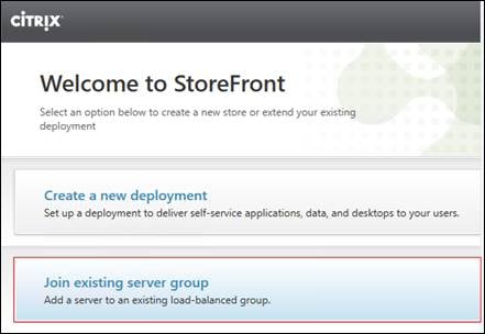
2. In the Join Server Group dialog, enter the name of the first Storefront server.
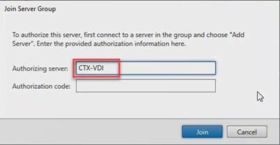
3. Before the additional StoreFront server can join the server group, you must connect to the first Storefront server, add the second server, and obtain the required authorization information.
4. Connect to the first StoreFront server.
5. Using the StoreFront menu on the left, you can scroll through the StoreFront management options.
6. Choose Server Group from the menu.
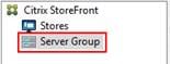
7. To add the second server and generate the authorization information that allows the additional StoreFront server to join the server group, click Add Server.
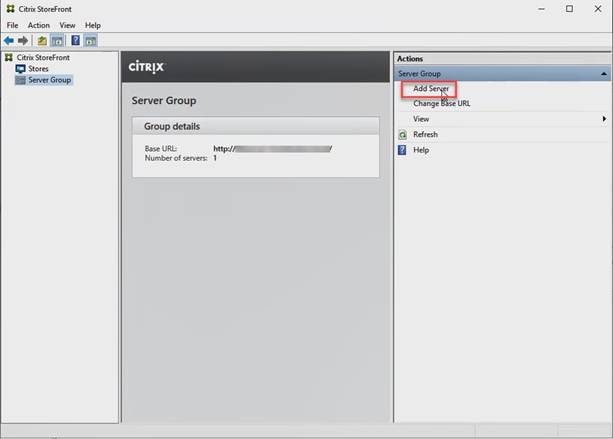
8. Copy the Authorization code from the Add Server dialog.
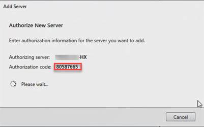
9. Connect to the second Storefront server and paste the Authorization code into the Join Server Group dialog.
10. Click Join.

11. A message appears when the second server has joined successfully.
12. Click OK.
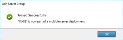
The second StoreFront is now in the Server Group.
Install the Citrix Provisioning Services Target Device Software
For non-persistent Windows 10 virtual desktops and Server 2019 RDS virtual machines, Citrix Provisioning Services (PVS) is used for deployment. The Master Target Device refers to the target device from which a hard disk image is built and stored on a vDisk. Provisioning Services then streams the contents of the vDisk created to other target devices. This procedure installs the PVS Target Device software that is used to build the RDS and VDI golden images.
To install the Citrix Provisioning Server Target Device software, follow these steps:
![]() Note: The instructions below outline the installation procedure to configure a vDisk for VDI desktops. When you have completed these installation steps, repeat the procedure to configure a vDisk for RDS.
Note: The instructions below outline the installation procedure to configure a vDisk for VDI desktops. When you have completed these installation steps, repeat the procedure to configure a vDisk for RDS.
1. On the Window 10 Master Target Device, launch the PVS installer from the Provisioning Services ISO.
2. Click Target Device Installation.
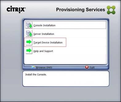
![]() Note: The installation wizard will check to resolve dependencies and then begin the PVS target device installation process.
Note: The installation wizard will check to resolve dependencies and then begin the PVS target device installation process.
3. Click Next.
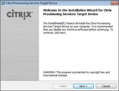
4. Confirm the installation settings and click Install.
5. Deselect the checkbox to launch the Imaging Wizard and click Finish.
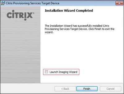
6. Reboot the machine.
Create Citrix Provisioning Services vDisks
The PVS Imaging Wizard automatically creates a base vDisk image from the master target device. To create the Citrix Provisioning Server vDisks, follow these steps:
![]() Note: The following procedure explains how to create a vDisk for VDI desktops. When you have completed these steps, repeat the procedure to build a vDisk for RDS.
Note: The following procedure explains how to create a vDisk for VDI desktops. When you have completed these steps, repeat the procedure to build a vDisk for RDS.
1. The PVS Imaging Wizard's Welcome page appears.
2. Click Next.
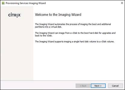
3. The Connect to Farm page appears. Enter the name or IP address of a Provisioning Server within the farm to connect to and the port to use to make that connection.
4. Use the Windows credentials (default) or enter different credentials.
5. Click Next.
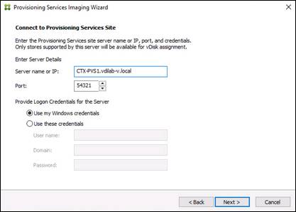
6. Choose Create new vDisk.
7. Click Next.
8. The Add Target Device page appears.
9. Select the Target Device Name, the MAC address associated with one of the NICs that was selected when the target device software was installed on the master target device, and the Collection to which you are adding the device.
10. Click Next.
11. The New vDisk dialog displays. Enter the name of the vDisk.
12. Select the Store where the vDisk will reside. Choose the vDisk type, either Fixed or Dynamic, from the drop-down menu. (This CVD used Dynamic rather than Fixed vDisks.)
13. Click Next.
14. On the Microsoft Volume Licensing page, choose the volume license option to use for target devices. For this CVD, volume licensing is not used, so the None button is selected.
15. Click Next.
16. Choose Image entire boot disk on the Configure Image Volumes page.
17. Click Next.
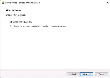
18. Choose Optimize for hard disk again for Provisioning Services before imaging on the Optimize Hard Disk for Provisioning Services.
19. Click Next.
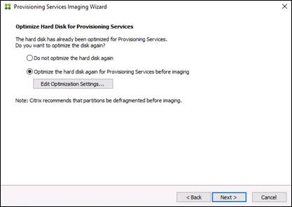
20. Choose Create on the Summary page.
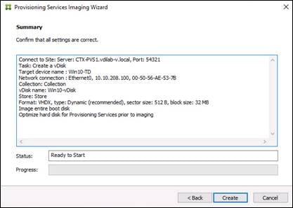
21. Review the configuration and click Continue.
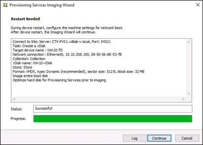
22. When prompted, click No to shut down the machine.
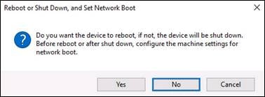
23. Edit the virtual machine settings and choose Boot options under VM Options.
24. Choose Force BIOS setup.
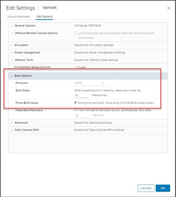
25. Restart Virtual Machine.
26. When the VM boots into the BIOS, got to ‘Boot’ menu to move the Network boot from VMware VMXNET3 to the top of the list.
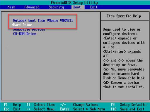
27. Restart Virtual Machine
![]() Note: After restarting the virtual machine, log into the VDI or RDS master target. The PVS imaging process begins, copying the contents of the C: drive to the PVS vDisk located on the server.
Note: After restarting the virtual machine, log into the VDI or RDS master target. The PVS imaging process begins, copying the contents of the C: drive to the PVS vDisk located on the server.
28. If prompted to Restart choose Restart Later.
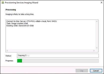
29. A message is displayed when the conversion is complete, click Done.
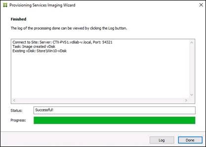
30. Shutdown the virtual machine used as the VDI or RDS master target.
31. Connect to the PVS server and validate that the vDisk image is available in the Store.
32. Right-click the newly created vDisk and choose Properties.
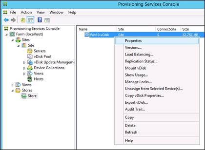
33. On the vDisk Properties dialog, change Access mode to “Private” mode so the Citrix Virtual Desktop Agent can be installed.
Install Citrix Virtual Apps and Desktop Virtual Desktop Agents
Virtual Delivery Agents (VDAs) are installed on the server and workstation operating systems and enable connections for desktops and apps. The following procedure was used to install VDAs for both HVD and HSD environments. VDAs must be installed on all images that will be used for VDI. For PVS and RDS, follow these steps AFTER you have imaged the machine and when it’s in Private Mode. For MCS, follow these steps when you are building your master image and BEFORE you deploy using the MCS steps.
To install Citrix Desktop Virtual Desktop Agents, follow these steps:
1. Launch the Citrix Desktop installer from the CVA Desktop 1912 LTSR ISO.
2. Click Start on the Welcome Screen.
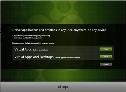
3. To install the VDA for the Hosted Virtual Desktops (VDI), choose Virtual Delivery Agent for Windows Desktop OS. After the VDA is installed for Hosted Virtual Desktops, repeat the procedure to install the VDA for Hosted Shared Desktops (RDS). In this case, choose Virtual Delivery Agent for Windows Server OS and follow the same basic steps.
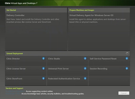
4. Choose Create a Master Image.(Be sure to choose the proper provisioning technology here)
5. Click Next.
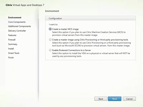
6. Optional: Choose Citrix Workspace App.
7. Click Next.
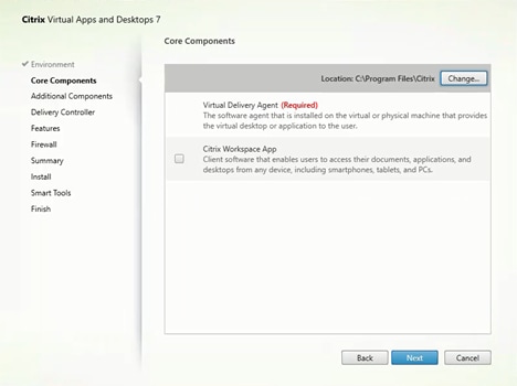
8. Click Next.
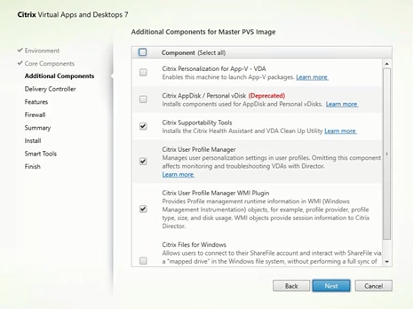
9. Choose “Do it manually” and specify the FQDN of the Delivery Controllers.
10. Click Next.
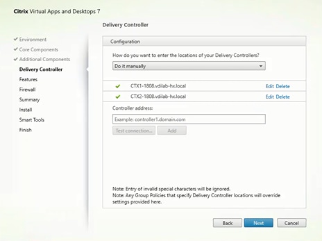
11. Accept the default features.
12. Click Next.
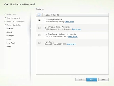
13. Allow the firewall rules to be configured automatically.
14. Click Next.
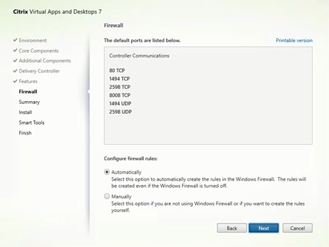
15. Verify the Summary and click Install.
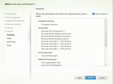
16. (Optional) Choose Call Home participation.
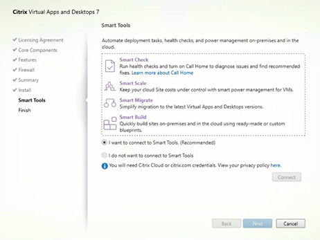
17. (Optional) check “Restart Machine.”
18. Click Finish.
19. Repeat these procedure so that VDAs are installed for both HVD (using the Windows 10 OS image) and the HSD desktops (using the Windows Server 2019 image).
20. Choose an appropriate workflow for the HSD desktop.
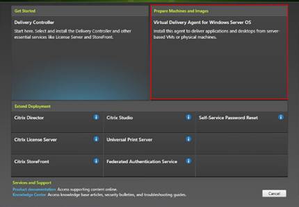
21. Once the Citrix VDA is installed, on the vDisk Properties dialog, change Access mode to “Standard Image (multi-device, read-only access)”.
22. Set the Cache Type to “Cache in device RAM with overflow on hard disk.”
23. Set Maximum RAM size (MBs): 256 for VDI and set 1024 MB for RDS vDisk.
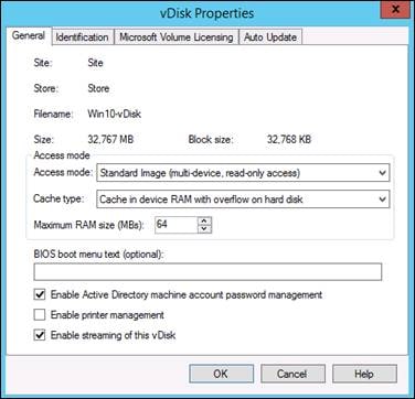
24. Click OK.
![]() Note: Repeat this procedure to create vDisks for both the Hosted VDI Desktops (using the Windows 10 OS image) and the Hosted Shared Desktops (using the Windows Server 2019 image).
Note: Repeat this procedure to create vDisks for both the Hosted VDI Desktops (using the Windows 10 OS image) and the Hosted Shared Desktops (using the Windows Server 2019 image).
Provision Virtual Desktop Machines Using Citrix Provisioning Server
To create VDI and RDS machines, follow these steps:
1. Choose the Master Target Device virtual machine from the VCenter Client.
2. Right-click the virtual machine and choose ‘Clone > Clone to Template’.
3. Name the cloned ‘Template’.
4. Choose the cluster and datastore where the first phase of provisioning will occur.
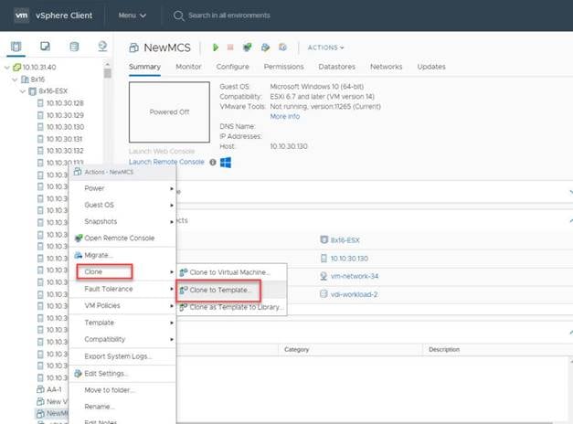
5. Name the template and click Next.
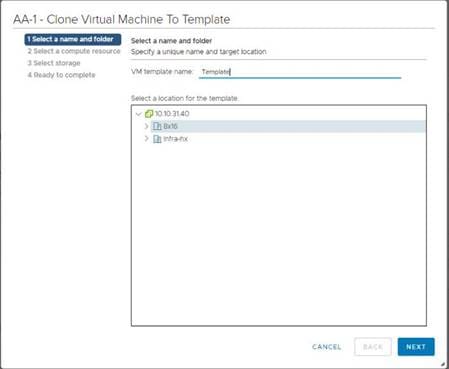
6. Choose a host in the cluster to place the template.
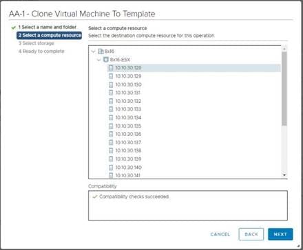
7. Click Next after selecting a datastore.
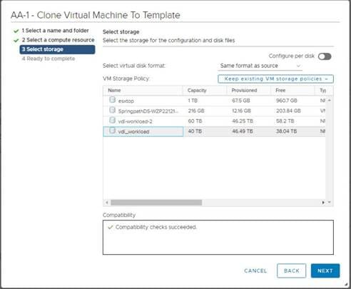
8. Click Next.
9. Click Next through the remaining screens
10. Click Finish to create the template.
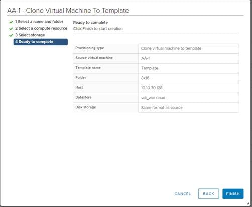
11. From Citrix Studio on the Desktop Controller, choose Hosting and Add Connection and Resources.
12. Choose Use an existing Connection and click Next.
13. Correspond the name of the resource with desktop machine clusters.
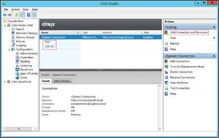
14. Browse and choose the VCenter cluster for desktop provisioning and use the default storage method Use storage shared by hypervisors.
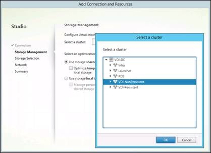
15. Choose the data storage location for the corresponding resource.
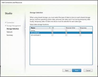
16. Choose the VDI networks for the desktop machines and click Next.
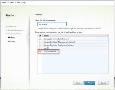
17. Click Finish.
![]() Note: Return to these settings to alter the datastore selection for each set of provisioned desktop machines if you want to create a separate datastore for each image.
Note: Return to these settings to alter the datastore selection for each set of provisioned desktop machines if you want to create a separate datastore for each image.
Provision Desktop Machines from Citrix Provisioning Services Console
To provision the desktop machines using the Citrix Provisioning Service Console, follow these steps on the Citrix Provisioning Server:
1. Start the Virtual Desktops Setup Wizard from the Provisioning Services Console.
2. Right-click the Site.
3. Choose Virtual Desktops Setup Wizard… from the context menu.
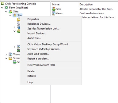
4. Click Next.
5. Enter the Virtual Desktops Controller address that will be used for the wizard operations.
6. Click Next.
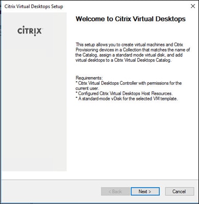
7. Choose the Host Resources on which the virtual machines will be created.
8. Click Next.
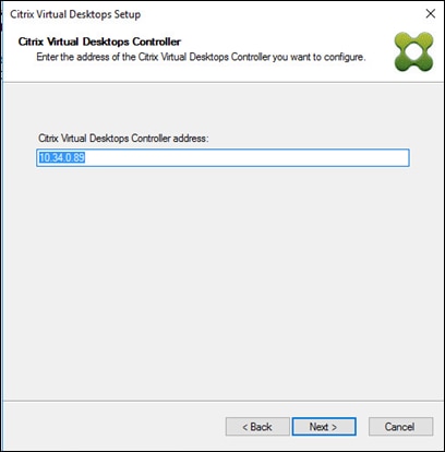
9. Provide the Host Resources Credentials (Username and Password) to the Virtual Desktops controller when prompted.
10. Click OK.
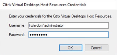
11. Choose the Template created earlier.
12. Click Next.
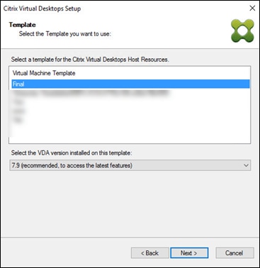
13. Choose the vDisk that will be used to stream virtual machines.
14. Click Next.
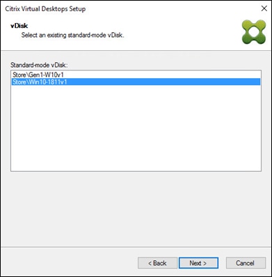
15. Choose “Create a new catalog.”
![]() Note: The catalog name is also used as the collection name in the PVS site.
Note: The catalog name is also used as the collection name in the PVS site.
16. Click Next.
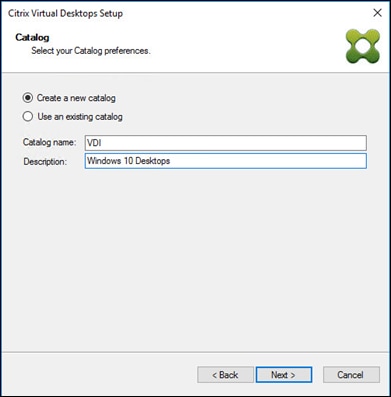
17. On the Operating System dialog, specify the operating system for the catalog. Specify Windows Desktop Operating System for VDI and Windows Server Operating System for RDS.
18. Click Next.
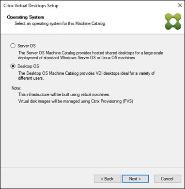
19. If you specified a Windows Desktop OS for VDIs, a User Experience dialog appears. Specify that the user will connect to “A fresh new (random) desktop each time.”
20. Click Next.
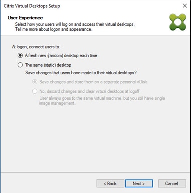
21. On the Virtual machines dialog, specify:
a. The number of virtual machines to create.
b. Number of vCPUs for the virtual machine (2 for VDI, 8 for RDS).
c. The amount of memory for the virtual machine (4GB for VDI, 24GB for RDS).
d. The write-cache disk size (10GB for VDI, 30GB for RDS).
e. PXE boot as the Boot Mode.
22. Click Next.
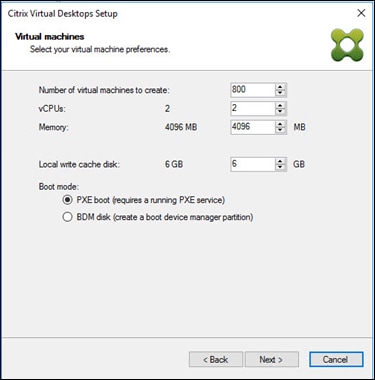
23. Choose the Create new accounts radio button.
24. Click Next.
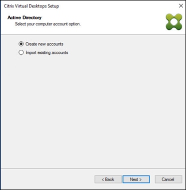
25. Specify the Active Directory Accounts and Location. This is where the wizard should create the computer accounts.
26. Provide the Account naming scheme. An example name is shown in the text box below the name scheme selection location.
27. Click Next.
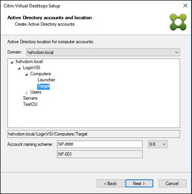
28. Click Finish to begin the virtual machine creation.

29. When the wizard is done provisioning the virtual machines, click Done.
30. Verify the desktop machines were successfully created in the following locations:
a. PVS1 > Provisioning Services Console > Farm > Site > Device Collections > VDI-NP > CTX-VDI-001
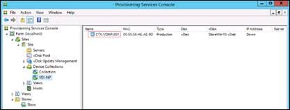
b. CTX-XD1 > Citrix Studio > Machine Catalogs > VDI-NP
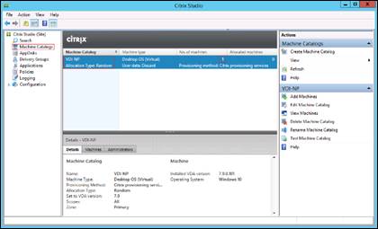
c. AD-DC1 > Active Directory Users and Computers > hxhvdom.local > Computers > CTX-VDI-001
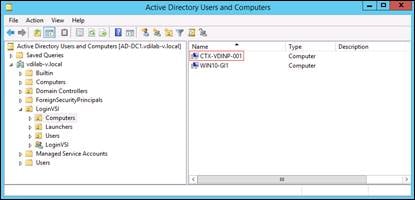
31. Log into the newly provisioned desktop machine, using the Virtual Disk Status verify the image mode is set to Ready Only and the cache type as Device Ram with overflow on local hard drive.
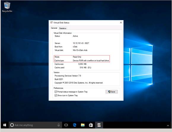
Deploy Virtual Machines using Citrix Machine Creation Services for Persistent Desktops
To create virtual machines for persistent use, follow these steps in the Citrix Studio:
1. Launch the Citrix Desktop Studio on the Delivery Controllers.
2. Right-click Machine Catalog and select Create Machine Catalog.
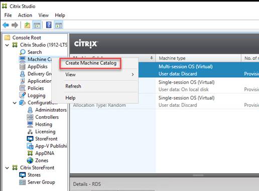
3. Click Next through the Introduction.
4. Select Single-Session OS and click Next.
5. Select Deploy machines using and ensure MCS is selected.
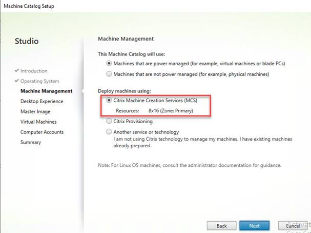
6. Select Static for the desktop experience and then select Yes, create a dedicated virtual machine.
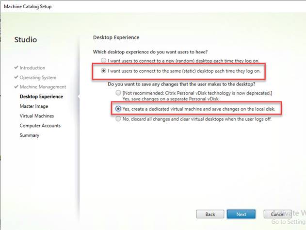
7. Chose the Master Image you want to deploy for your persistent VMs.
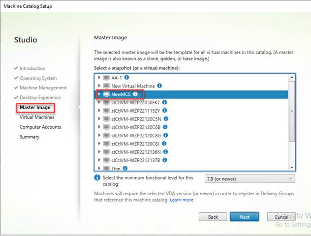
8. Enter the number of VMs you want to deploy and we HIGHLY recommend using full copy mode when deploying on HyperFlex.
9. Click Next.
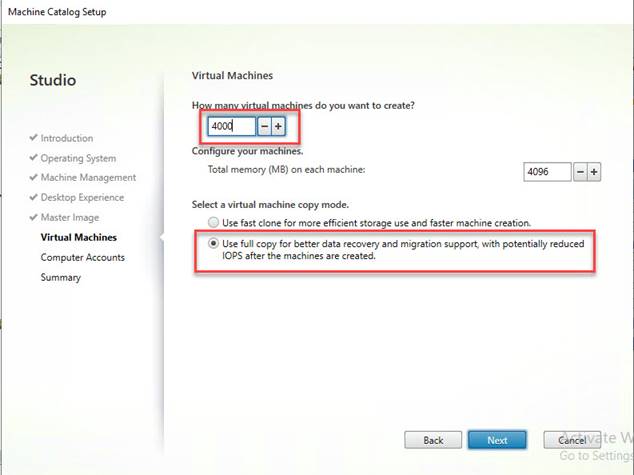
10. Select the domain, Org Unit and naming convention for your VMs (the ### represents the number of digits in the VM name, in this study because we had 4000 machines, we needed four ####)
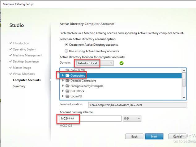
11. Click Next.
12. Provide a name for the catalog and click Finish.
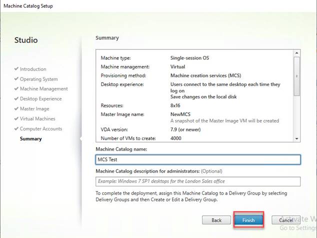
13. The machines will clone quickly and are will be ready to put into Delivery Groups when done.
Create Delivery Groups
Delivery Groups are collections of machines that control access to desktops and applications. With Delivery Groups, you can specify which users and groups can access which desktops and applications.
To create delivery groups, follow these steps:
![]() Note: The instructions below outline the steps to create a Delivery Group for VDI desktops. When you have completed these steps, repeat the procedure to a Delivery Group for HVD desktops.
Note: The instructions below outline the steps to create a Delivery Group for VDI desktops. When you have completed these steps, repeat the procedure to a Delivery Group for HVD desktops.
1. Connect to a Virtual Desktops server and launch Citrix Studio.
2. Choose Create Delivery Group from the drop-down list.
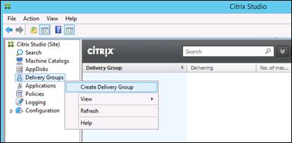
3. Click Next.
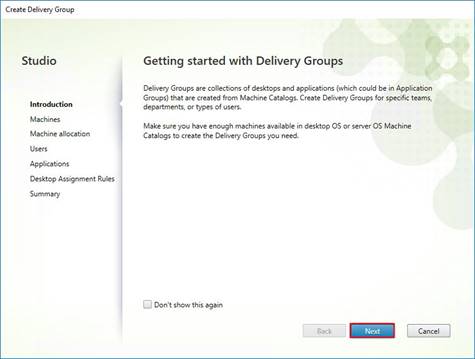
4. Choose Machine catalog.
5. Provide the number of machines to be added to the delivery Group.
6. Click Next.
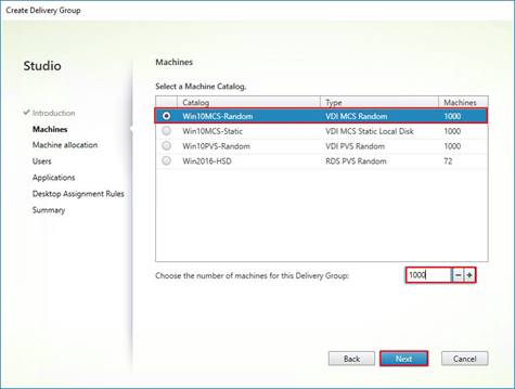
7. To make the Delivery Group accessible, you must add users, choose Allow any authenticated users to use this Delivery Group.
8. Click Next.

![]() Note: User assignment can be updated any time after Delivery group creation by accessing Delivery group properties in Desktop Studio.
Note: User assignment can be updated any time after Delivery group creation by accessing Delivery group properties in Desktop Studio.
9. (Optional) specify Applications catalog will deliver.
10. Click Next.
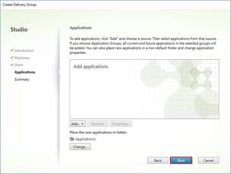
11. On the Summary dialog, review the configuration. Enter a Delivery Group name and a Display name (for example, HVD or HSD).
12. Click Finish.
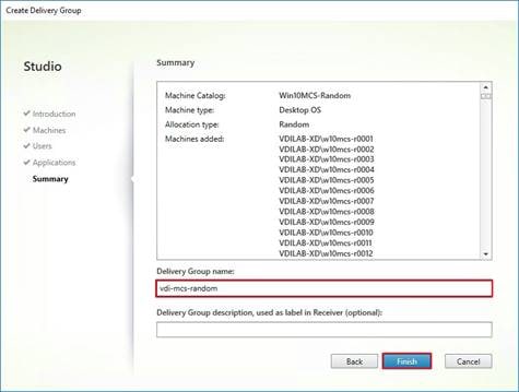
13. Citrix Studio lists the created Delivery Groups and the type, number of machines created, sessions, and applications for each group in the Delivery Groups tab. Choose Delivery Group and in Action List, select “Turn on Maintenance Mode.”
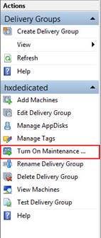
Citrix Virtual Desktops Policies and Profile Management
Policies and profiles allow the Citrix Virtual Desktops environment to be easily and efficiently customized.
Configure Citrix Virtual Desktops Policies
Citrix Virtual Desktops policies control user access and session environments, and are the most efficient method of controlling connection, security, and bandwidth settings. You can create policies for specific groups of users, devices, or connection types with each policy. Policies can contain multiple settings and are typically defined through Citrix Studio. (The Windows Group Policy Management Console can also be used if the network environment includes Microsoft Active Directory and permissions are set for managing Group Policy Objects). Figure 44 shows policies for Login VSI testing in this CVD.
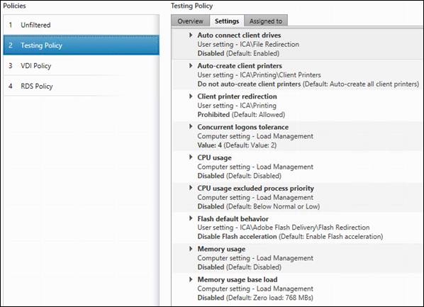
Configure User Profile Management
Profile management provides an easy, reliable, and high-performance way to manage user personalization settings in virtualized or physical Windows environments. It requires minimal infrastructure and administration and provides users with fast logons and logoffs. A Windows user profile is a collection of folders, files, registry settings, and configuration settings that define the environment for a user who logs on with a particular user account. These settings may be customizable by the user, depending on the administrative configuration. Examples of settings that can be customized are:
· Desktop settings such as wallpaper and screen saver
· Shortcuts and Start menu setting
· Internet Explorer Favorites and Home Page
· Microsoft Outlook signature
· Printers
Some user settings and data can be redirected by means of folder redirection. However, if folder redirection is not used these settings are stored within the user profile.
The first stage in planning a profile management deployment is to decide on a set of policy settings that together form a suitable configuration for your environment and users. The automatic configuration feature simplifies some of this decision-making for Virtual Desktops deployments. Screenshots of the User Profile Management interfaces that establish policies for this CVD’s RDS and VDI users (for testing purposes) are shown below.
Basic profile management policy settings are documented here: https://docs.citrix.com/en-us/citrix-virtual-apps-desktops
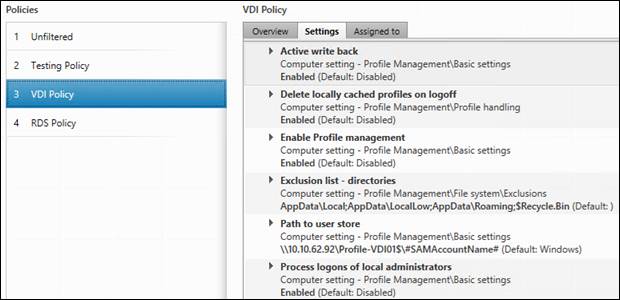
In this project, we tested a single Cisco HyperFlex cluster running four Cisco UCS HXAF220C-M5SX Rack Servers in a single Cisco UCS domain. This solution is tested to illustrate linear scalability for each workload studied.
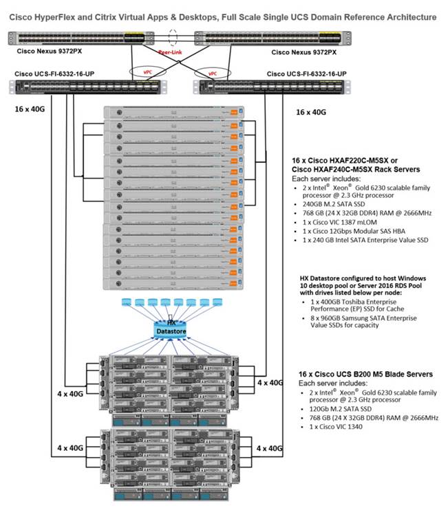
Hardware Components:
· 2 x Cisco UCS 6454 Fabric Interconnects
· 2 x Cisco Nexus 93108YCPX Access Switches
· 8 x Cisco UCS HXAF220c-M5SX Rack Servers (2 Intel Xeon Gold 6230 scalable family processor at 2.1 GHz, with 768 GB of memory per server [64 GB x 12 DIMMs at 2933 MHz])
· 16 x Cisco UCS B200 M5 Blade Servers (2 Intel Xeon Gold 6230 scalable family processor at 2.1 GHz, with 768 GB of memory per server [64 GB x 12 DIMMs at 2933 MHz])
· Cisco VIC 1457 mLOM
· 12G modular SAS HBA Controller
· 240GB M.2 SATA SSD drive (Boot and HyperFlex Data Platform controller virtual machine)
· 240GB 2.5” 6G SATA SSD drive (Housekeeping)
· 400GB 2.5” 6G SAS SSD drive (Cache)
· 6 x 960GB 2.5” SATA SSD drive (Capacity)
· 1 x 32GB mSD card (Upgrades temporary cache)
Software Components:
· Cisco UCS firmware 4.0(4g)
· Cisco HyperFlex Data Platform 4.0.2a
· VMWare ESXi 6.7.0 15160138
· Citrix Virtual Desktops 1912 LTSR
· Citrix User Profile Management
· Microsoft SQL Server 2019
· Microsoft Windows 10, Build 1909
· Microsoft Windows 2019
· Microsoft Office 2016
· Login VSI 4.1.32
Test Methodology and Success Criteria
All validation testing was conducted on-site within the Cisco labs in San Jose, California.
The testing results focused on the entire process of the virtual desktop lifecycle by capturing metrics during the desktop boot-up, user logon and virtual desktop acquisition (also referred to as ramp-up,) user workload execution (also referred to as steady state), and user logoff for the Hosted Shared Desktop Session under test.
Test metrics were gathered from the virtual desktop, storage, and load generation software to assess the overall success of an individual test cycle. Each test cycle was not considered passing unless all of the planned test users completed the ramp-up and steady state phases (described below) and unless all metrics were within the permissible thresholds as noted as success criteria.
Three successfully completed test cycles were conducted for each hardware configuration and results were found to be relatively consistent from one test to the next.
You can obtain additional information and a free test license from http://www.loginvsi.com.
Test Procedure
The following protocol was used for each test cycle in this study to insure consistent results.
Pre-Test Setup for Testing
All machines were shut down utilizing the Citrix Virtual Desktops 1912 LTSR Administrator Console.
All Launchers for the test were shut down. They were then restarted in groups of 10 each minute until the required number of launchers was running with the Login VSI Agent at a “waiting for test to start” state.
Test Run Protocol
To simulate severe, real-world environments, Cisco requires the log-on and start-work sequence, known as Ramp Up, to complete in 48 minutes. Additionally, we require all sessions started, whether 60 single server users or 4000 full scale test users to become active within two minutes after the last session is launched.
In addition, Cisco requires that the Login VSI Benchmark method is used for all single server and scale testing. This assures that our tests represent real-world scenarios. For each of the three consecutive runs on single server tests, the same process was followed. To run the test protocol, follow these steps:
1. Time 0:00:00 Start esxtop Logging on the following systems:
- Infrastructure and VDI Host Blades used in test run
- All Infrastructure virtual machines used in test run (AD, SQL, View Connection brokers, image mgmt., and so on)
2. Time 0:00:10 Start Storage Partner Performance Logging on Storage System.
3. Time 0:05: Boot RDS Machines using Citrix Virtual Desktops 1912 LTSR Administrator Console.
4. Time 0:06 First machines boot.
5. Time 0:35 Single Server or Scale target number of RDS Servers registered on XD.
![]() Note: No more than 60 Minutes of rest time is allowed after the last desktop is registered and available on Citrix Virtual Desktops 1912 LTSR Administrator Console dashboard. Typically, a 20-30 minute rest period for Windows 10 desktops and 10 minutes for RDS virtual machines is sufficient.
Note: No more than 60 Minutes of rest time is allowed after the last desktop is registered and available on Citrix Virtual Desktops 1912 LTSR Administrator Console dashboard. Typically, a 20-30 minute rest period for Windows 10 desktops and 10 minutes for RDS virtual machines is sufficient.
6. Time 1:35 Start Login VSI 4.1.32 Knowledge Worker Benchmark Mode Test, setting auto-logoff time at 900 seconds, with Single Server or Scale target number of desktop virtual machines utilizing sufficient number of Launchers (at 20-25 sessions/Launcher).
7. Time 2:23 Single Server or Scale target number of desktop virtual machines desktops launched (48-minute benchmark launch rate).
8. Time 2:25 All launched sessions must become active.
![]() Note: All sessions launched must become active for a valid test run within this window.
Note: All sessions launched must become active for a valid test run within this window.
9. Time 2:40 Login VSI Test Ends (based on Auto Logoff 900 Second period designated above).
10. Time 2:55 All active sessions logged off.
11. All sessions launched and active must be logged off for a valid test run. The Citrix Virtual Desktops 1912 LTSR Administrator Dashboard must show that all desktops have been returned to the registered/available state as evidence of this condition being met.
12. Time 2:57 All logging terminated; Test complete.
13. Time 3:15 Copy all log files off to archive; Set virtual desktops to maintenance mode through broker; Shutdown all Windows 7 machines.
14. Time 3:30 Reboot all hypervisors.
15. Time 3:45 Ready for new test sequence.
Success Criteria
Our “pass” criteria for this testing is as follows: Cisco will run tests at a session count levels that effectively utilize the server capacity measured by CPU, memory, storage and network utilization. We use Login VSI version 4.1.25 to launch Knowledge Worker workload sessions. The number of launched sessions must equal active sessions within two minutes of the last session launched in a test as observed on the VSI Management console.
The Citrix Virtual Desktops Studio will be monitored throughout the steady state to make sure of the following:
· All running sessions report In Use throughout the steady state
· No sessions move to unregistered, unavailable or available state at any time during steady state
Within 20 minutes of the end of the test, all sessions on all launchers must have logged out automatically and the Login VSI Agent must have shut down. Cisco’s tolerance for Stuck Sessions is 0.5 percent (half of one percent.) If the Stuck Session count exceeds that value, we identify it as a test failure condition.
Cisco requires three consecutive runs with results within +/-1 percent variability to pass the Cisco Validated Design performance criteria. For white papers written by partners, two consecutive runs within +/-1 percent variability are accepted. (All test data from partner run testing must be supplied along with proposed white paper.)
We will publish Cisco Validated Designs with our recommended workload following the process above and will note that we did not reach a VSImax dynamic in our testing.
The purpose of this testing is to provide the data needed to validate Citrix Virtual Desktops 1912 LTSR Hosted Shared Desktop with Citrix Virtual Desktops 1912 LTSR Composer provisioning using Microsoft Windows Server 2016 sessions on Cisco UCS HXAF220c-M4S, Cisco UCS 220 M4 and Cisco UCS B200 M4 servers.
The information contained in this section provides data points that a customer may reference in designing their own implementations. These validation results are an example of what is possible under the specific environment conditions outlined here and do not represent the full characterization of Citrix and Microsoft products.
Four test sequences, each containing three consecutive test runs generating the same result, were performed to establish system performance and linear scalability.
VSImax 4.1.x Description
The philosophy behind Login VSI is different to conventional benchmarks. In general, most system benchmarks are steady state benchmarks. These benchmarks execute one or multiple processes, and the measured execution time is the outcome of the test. Simply put: the faster the execution time or the bigger the throughput, the faster the system is according to the benchmark.
Login VSI is different in approach. Login VSI is not primarily designed to be a steady state benchmark (however, if needed, Login VSI can act like one). Login VSI was designed to perform benchmarks for SBC or VDI workloads through system saturation. Login VSI loads the system with simulated user workloads using well known desktop applications like Microsoft Office, Internet Explorer and Adobe PDF reader. By gradually increasing the number of simulated users, the system will eventually be saturated. Once the system is saturated, the response time of the applications will increase significantly. This latency in application response times show a clear indication whether the system is (close to being) overloaded. As a result, by nearly overloading a system it is possible to find out what is its true maximum user capacity.
After a test is performed, the response times can be analyzed to calculate the maximum active session/desktop capacity. Within Login VSI this is calculated as VSImax. When the system is coming closer to its saturation point, response times will rise. When reviewing the average response time, it will be clear the response times escalate at saturation point.
This VSImax is the “Virtual Session Index (VSI)”. With Virtual Desktop Infrastructure (VDI) and Terminal Services (RDS) workloads this is valid and useful information. This index simplifies comparisons and makes it possible to understand the true impact of configuration changes on hypervisor host or guest level.
Server-Side Response Time Measurements
It is important to understand why specific Login VSI design choices have been made. An important design choice is to execute the workload directly on the target system within the session instead of using remote sessions. The scripts simulating the workloads are performed by an engine that executes workload scripts on every target system and are initiated at logon within the simulated user’s desktop session context.
An alternative to the Login VSI method would be to generate user actions client side through the remoting protocol. These methods are always specific to a product and vendor dependent. More importantly, some protocols simply do not have a method to script user actions client side.
For Login VSI the choice has been made to execute the scripts completely server side. This is the only practical and platform independent solutions, for a benchmark like Login VSI.
Calculating VSImax v4.1.x
The simulated desktop workload is scripted in a 48-minute loop when a simulated Login VSI user is logged on, performing generic Office worker activities. After the loop is finished it will restart automatically. Within each loop the response times of sixteen specific operations are measured in a regular interval: sixteen times in within each loop. The response times of these five operations are used to determine VSImax.
The five operations from which the response times are measured are:
· Notepad File Open (NFO)
Loading and initiating VSINotepad.exe and opening the openfile dialog. This operation is handled by the OS and by the VSINotepad.exe itself through execution. This operation seems almost instant from an end-user’s point of view.
· Notepad Start Load (NSLD)
Loading and initiating VSINotepad.exe and opening a file. This operation is also handled by the OS and by the VSINotepad.exe itself through execution. This operation seems almost instant from an end-user’s point of view.
· Zip High Compression (ZHC)
This action copy's a random file and compresses it (with 7zip) with high compression enabled. The compression will very briefly spike CPU and disk IO.
· Zip Low Compression (ZLC)
This action copy's a random file and compresses it (with 7zip) with low compression enabled. The compression will very briefly disk IO and creates some load on the CPU.
· CPU
Calculates a large array of random data and spikes the CPU for a short period of time.
These measured operations within Login VSI do hit considerably different subsystems such as CPU (user and kernel), Memory, Disk, the OS in general, the application itself, print, GDI, etc. These operations are specifically short by nature. When such operations become consistently long: the system is saturated because of excessive queuing on any kind of resource. As a result, the average response times will then escalate. This effect is clearly visible to end-users. If such operations consistently consume multiple seconds the user will regard the system as slow and unresponsive.


When the test is finished, VSImax can be calculated. When the system is not saturated, and it could complete the full test without exceeding the average response time latency threshold, VSImax is not reached and the amount of sessions ran successfully.
The response times are very different per measurement type, for instance Zip with compression can be around 2800 ms, while the Zip action without compression can only take 75ms. This response time of these actions are weighted before they are added to the total. This ensures that each activity has an equal impact on the total response time.
In comparison to previous VSImax models, this weighting much better represents system performance. All actions have very similar weight in the VSImax total. The following weighting of the response times are applied.
The following actions are part of the VSImax v4.1 calculation and are weighted as follows (US notation):
· Notepad File Open (NFO): 0.75
· Notepad Start Load (NSLD): 0.2
· Zip High Compression (ZHC): 0.125
· Zip Low Compression (ZLC): 0.2
· CPU: 0.75
This weighting is applied on the baseline and normal Login VSI response times.
With the introduction of Login VSI 4.1 we also created a new method to calculate the base phase of an environment. With the new workloads (Taskworker, Powerworker, etc.) enabling 'base phase' for a more reliable baseline has become obsolete. The calculation is explained below. In total 15 lowest VSI response time samples are taken from the entire test, the lowest 2 samples are removed, and the 13 remaining samples are averaged. The result is the Baseline. The calculation is as follows:
· Take the lowest 15 samples of the complete test
· From those 15 samples remove the lowest 2
· Average the 13 results that are left is the baseline
The VSImax average response time in Login VSI 4.1.x is calculated on the number of active users that are logged on the system.
Always a 5 Login VSI response time samples are averaged + 40 percent of the amount of “active” sessions. For example, if the active sessions are 60, then latest 5 + 24 (=40 percent of 60) = 31 response time measurement are used for the average calculation.
To remove noise (accidental spikes) from the calculation, the top 5 percent and bottom 5 percent of the VSI response time samples are removed from the average calculation, with a minimum of 1 top and 1 bottom sample. As a result, with 60 active users, the last 31 VSI response time sample are taken. From those 31 samples the top 2 samples are removed and lowest 2 results are removed (5 percent of 31 = 1.55, rounded to 2). At 60 users the average is then calculated over the 27 remaining results.
VSImax v4.1.x is reached when the VSIbase + a 1000 ms latency threshold is not reached by the average VSI response time result. Depending on the tested system, VSImax response time can grow 2 - 3x the baseline average. In end-user computing, a 3x increase in response time in comparison to the baseline is typically regarded as the maximum performance degradation to be considered acceptable.
In VSImax v4.1.x this latency threshold is fixed to 1000ms, this allows better and fairer comparisons between two different systems, especially when they have different baseline results. Ultimately, in VSImax v4.1.x, the performance of the system is not decided by the total average response time, but by the latency is has under load. For all systems, this is now 1000ms (weighted).
The threshold for the total response time is: average weighted baseline response time + 1000ms.
When the system has a weighted baseline response time average of 1500ms, the maximum average response time may not be greater than 2500ms (1500+1000). If the average baseline is 3000 the maximum average response time may not be greater than 4000ms (3000+1000).
When the threshold is not exceeded by the average VSI response time during the test, VSImax is not hit and the amount of sessions ran successfully. This approach is fundamentally different in comparison to previous VSImax methods, as it was always required to saturate the system beyond VSImax threshold.
Lastly, VSImax v4.1.x is now always reported with the average baseline VSI response time result. For example: “The VSImax v4.1 was 125 with a baseline of 1526ms”. This helps considerably in the comparison of systems and gives a more complete understanding of the system. The baseline performance helps to understand the best performance the system can give to an individual user. VSImax indicates what the total user capacity is for the system. These two are not automatically connected and related:
When a server with a very fast dual core CPU, running at 3.6 GHZ, is compared to a 10 core CPU, running at 2,26 GHZ, the dual core machine will give and individual user better performance than the 10 core machine. This is indicated by the baseline VSI response time. The lower this score is, the better performance an individual user can expect.
However, the server with the slower 10 core CPU will easily have a larger capacity than the faster dual core system. This is indicated by VSImax v4.1.x, and the higher VSImax is, the larger overall user capacity can be expected.
With Login VSI 4.1.x a new VSImax method is introduced: VSImax v4.1. This methodology gives much better insight in system performance and scales to extremely large systems.
Boot Storms
A key performance metric for desktop virtualization environments is the ability to boot the virtual machines quickly and efficiently to minimize user wait time for their desktop.
As part of Cisco’s virtual desktop test protocol, we shut down each virtual machine at the conclusion of a benchmark test. When we run a new test, we cold boot all 4000 desktops and measure the time it takes for the 1244th virtual machine to register as available in the Virtual Desktops Administrator console.
The Cisco HyperFlex HXAF220c-M5SX based All-Flash cluster running Data Platform version 4.0.2a software can accomplish this task in 35 minutes.
Recommended Maximum Workload and Configuration Guidelines
Twenty-four Nodes Total with Eight Cisco HXAF220c-M5S Rack-Mount Server, Sixteen Cisco UCS B200 M5 Compute Nodes and HyperFlex All-Flash Cluster
For Citrix Virtual Apps RDS Hosted Shared Desktop and Hosted Virtual Desktop use case, the recommended maximum workload was determined based on both Login VSI Knowledge Worker workload end user experience measures and HXAF220c-M5SX server operating parameters.
This recommended maximum workload approach allows you to determine the server N+1 fault tolerance load the blade can successfully support in the event of a server outage for maintenance or upgrade.
Our recommendation is that the Login VSI Average Response and VSI Index Average should not exceed the Baseline plus 2000 milliseconds to ensure that end-user experience is outstanding. Additionally, during steady state, the processor utilization should average no more than 90-95 percent.
![]() Note: Memory should never be oversubscribed for Desktop Virtualization workloads.
Note: Memory should never be oversubscribed for Desktop Virtualization workloads.
| Test Phase |
Description |
| Boot |
Start all RDS and/or VDI virtual machines at the same time. |
| Login |
The Login VSI phase of test is where sessions are launched and start executing the workload over a 48 minutes duration. |
| Steady state |
The steady state phase is where all users are logged in and performing various workload tasks such as using Microsoft Office, Web browsing, PDF printing, playing videos, and compressing files. |
| Logoff |
Sessions finish executing the Login VSI workload and logoff. |
![]() Note: The recommended maximum workload for a Cisco HyperFlex cluster configured on Cisco HXAF220c-M5SX with Intel Xeon Gold 6230 scalable family processors and 768GB of RAM for Windows 10 desktops with Office 2016 is 4000 virtual desktops.
Note: The recommended maximum workload for a Cisco HyperFlex cluster configured on Cisco HXAF220c-M5SX with Intel Xeon Gold 6230 scalable family processors and 768GB of RAM for Windows 10 desktops with Office 2016 is 4000 virtual desktops.
![]() Note: The recommended maximum workload for a Cisco HyperFlex cluster configured on Cisco HXAF220c-M5SX with Intel Xeon Gold 6230 scalable family processors and 768GB of RAM for Windows Server 2019 RDS desktop sessions with Office 2016 is 5000 virtual desktops.
Note: The recommended maximum workload for a Cisco HyperFlex cluster configured on Cisco HXAF220c-M5SX with Intel Xeon Gold 6230 scalable family processors and 768GB of RAM for Windows Server 2019 RDS desktop sessions with Office 2016 is 5000 virtual desktops.
5000 RDS Sessions, 4000 Windows 10 Citrix PVS Non-Persistent, and 4000 Windows 10 Citrix MCS Persistent desktops Testing on 24 Node Cisco HyperFlex Cluster
Hosted Shared desktops with 5000 user sessions on 250 Windows Server 2019 virtual machines on a 24-node HyperFlex cluster.
Test results for 5000 user sessions on Citrix RDS highlights include:
· 0.713 second baseline response time
· 1.058 second average response time with 5000 desktops running
· Average CPU utilization of 75 percent during steady state
· Average of 300 GB of RAM used out of 768 GB available
· 4,000 peak I/O operations per second (IOPS) per cluster at steady state
· 200-250MBps peak throughput per cluster at steady state
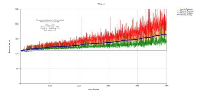
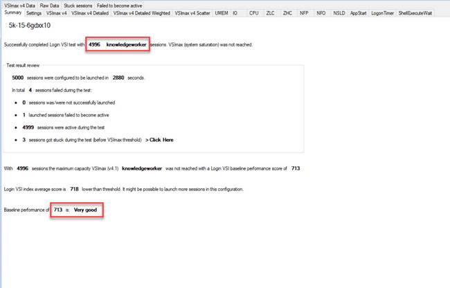
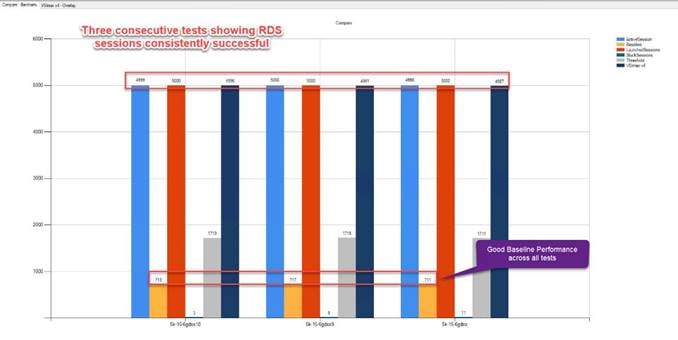
ESX Host Performance Counters
When running a VMware ESXi environment for our Citrix Virtual Desktop workloads, it’s important to monitor a few key performance counters to ensure the best end-user experience. We typically look for CPU utilization, memory availability, network throughput and Storage performance:
· CPU Performance: With VMware ESXi, using esxtop, our main counter is % Core Utilization.
· Memory Availability: We measure the memory available in megabytes to ensure that memory is not being consumed at a high level.
· Network throughput: We measure the bytes sent and received by the VM Network and Storage vSwitches on each ESXi HX Host.
· Storage performance: We use HyperFlex Connect to monitor and review storage performance during VDI.
The following figures show the results of our workload testing:
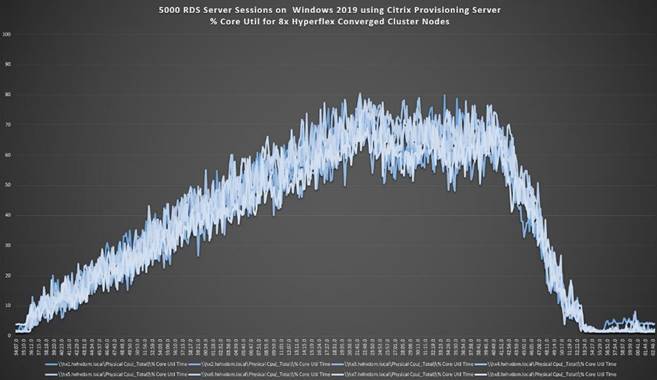
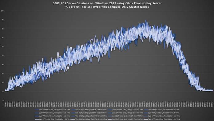
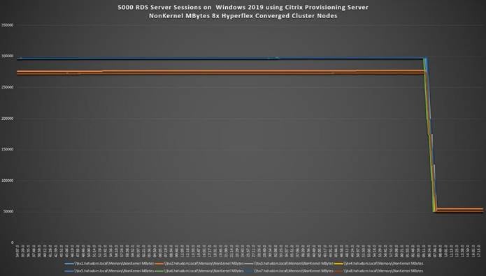
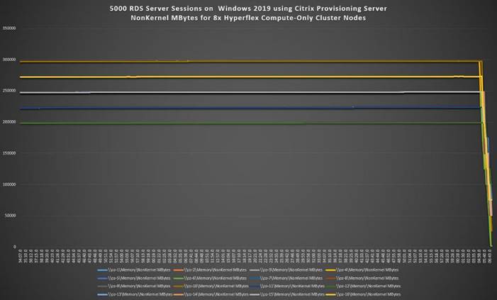
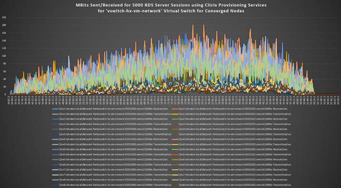
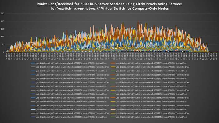
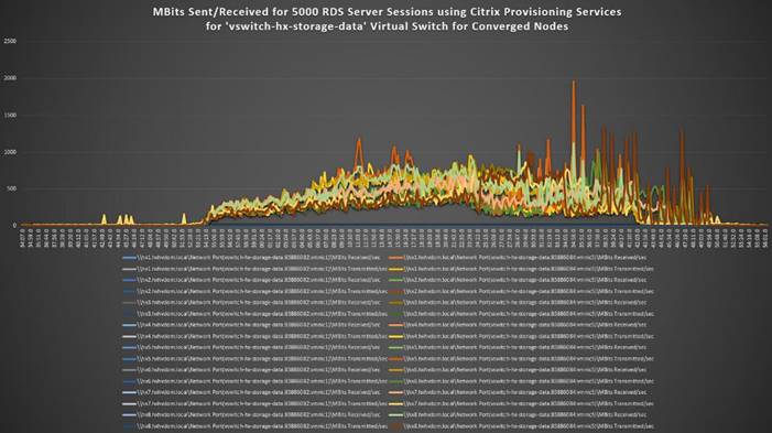
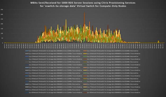
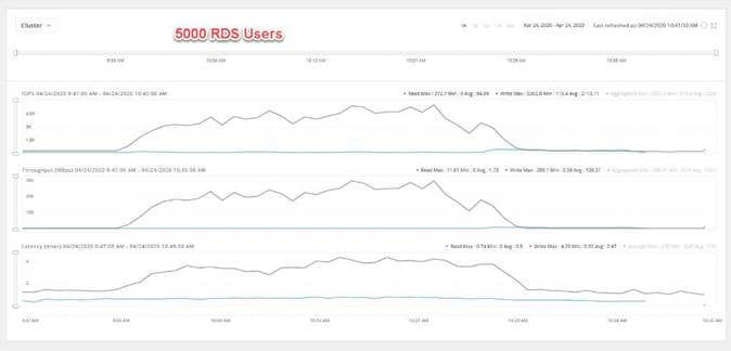
Test results for 4000 Citrix VDI non-persistent Desktops using Citrix Provisioning Services highlights include:
· 0.827 second baseline response time
· 1.152 second average response time with 4000 desktops running
· Average CPU utilization of 75 percent during steady state
· Average of 550 GB of RAM used out of 768 GB available
· 6500 peak I/O operations per second (IOPS) per cluster at steady state
· 150MBps peak throughput per cluster at steady state
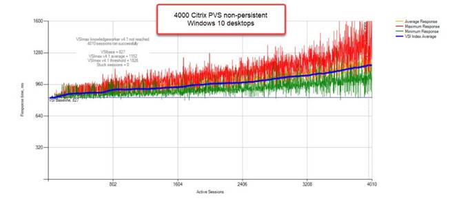
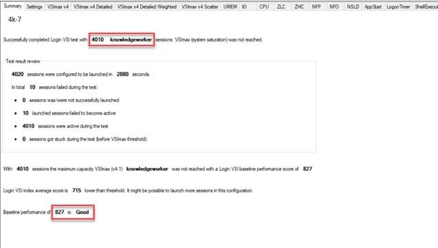
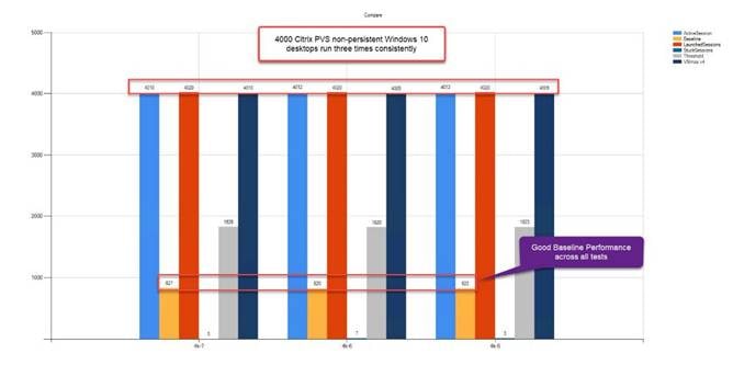
ESX Host Performance Counters
When running a VMware ESXi environment for our Citrix Virtual Desktop workloads, it’s important to monitor a few key performance counters to ensure the best end-user experience. We typically look for CPU utilization, memory availability, network throughput and Storage performance:
· CPU Performance: With VMware ESXi, using esxtop, our main counter is % Core Utilization.
· Memory Availability: We measure the memory available in megabytes to ensure that memory is not being consumed at a high level.
· We measure the bytes sent and received by the VM Network and Storage vSwitches on each ESXi HX Host. Storage performance: We use HyperFlex Connect to monitor and review storage performance during VDI.
The following figures show the results of our workload testing:
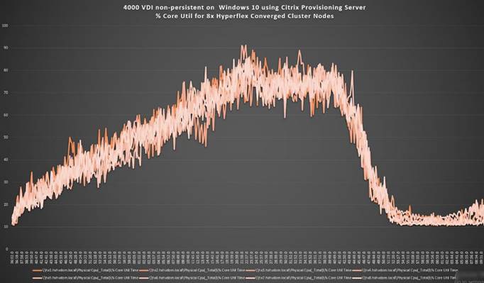
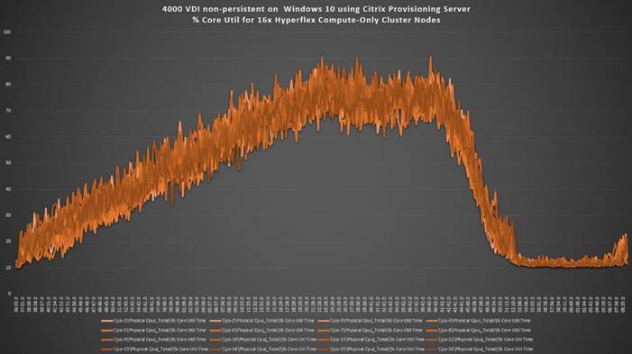
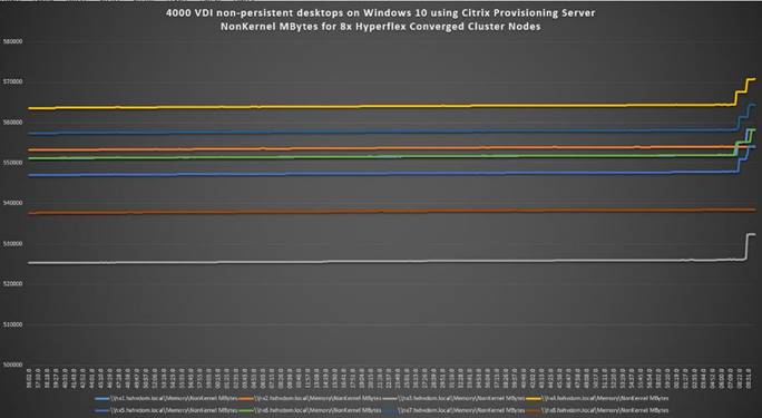
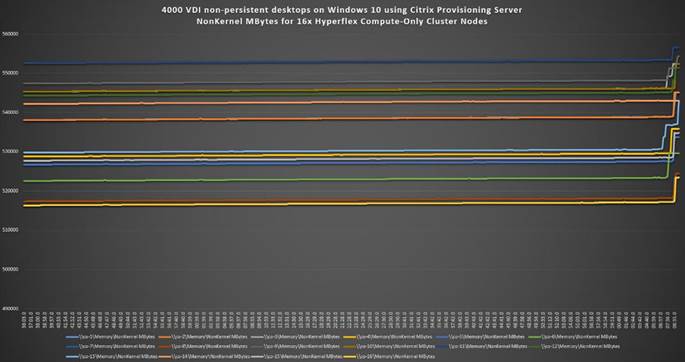
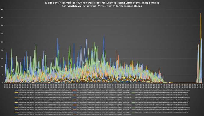
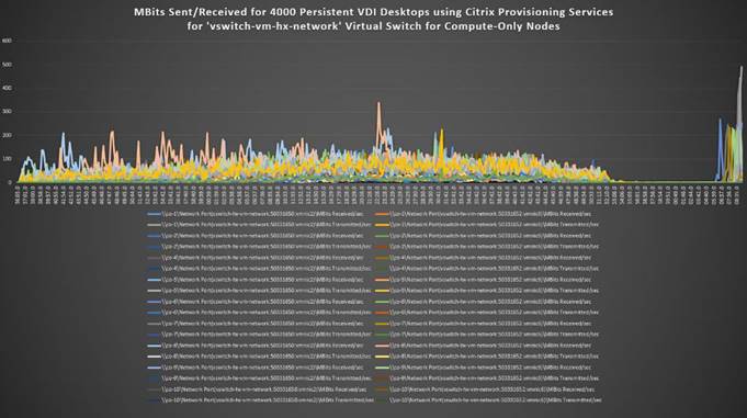
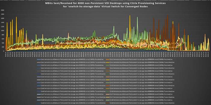
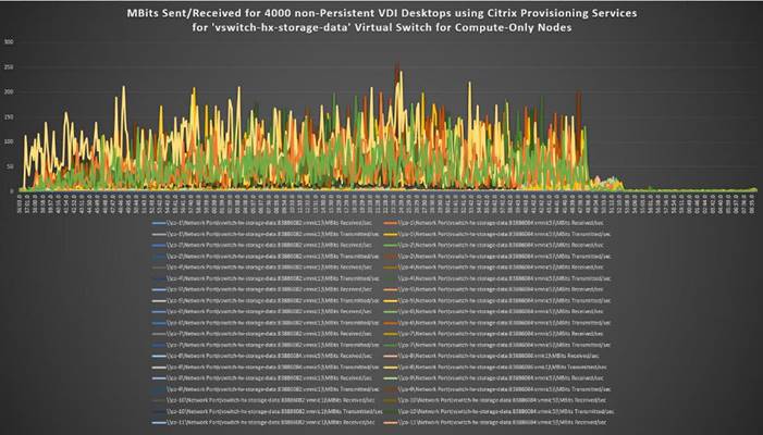
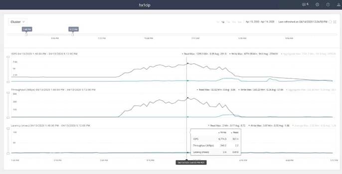
Test results for 4000 Citrix VDI Persistent Desktops using Machine Creation Services highlights include:
· 0.819 second baseline response time
· 1.113 second average response time with 4000 desktops running
· Average CPU utilization of 70 percent during steady state
· Average of 550 GB of RAM used out of 768 GB available
· 21,000 peak I/O operations per second (IOPS) per cluster at steady state
· 536 MBps peak throughput per cluster at steady state
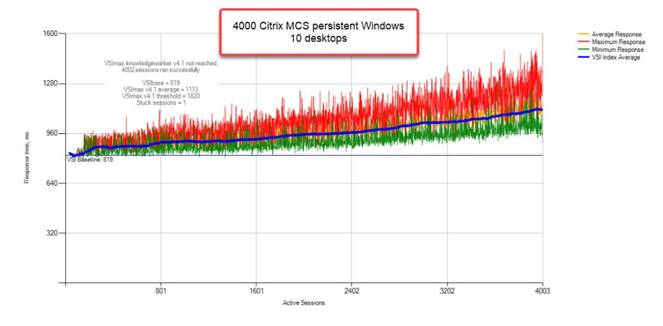
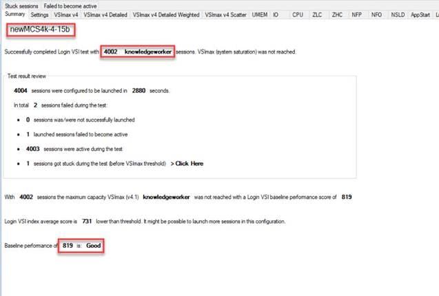
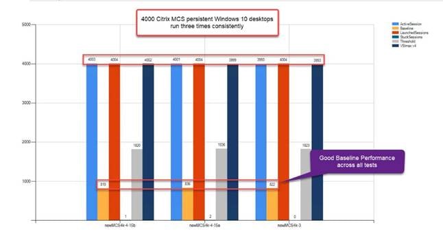
ESX Host Performance Counters
When running a VMware ESXi environment for our Citrix Virtual Desktop workloads, it’s important to monitor a few key performance counters to ensure the best end-user experience. We typically look for CPU utilization, memory availability, network throughput and Storage performance:
· CPU Performance: With VMware ESXi, using esxtop, our main counter is % Core Utilization.
· Memory Availability: We measure the memory available in megabytes to ensure that memory is not being consumed at a high level.
· We measure the bytes sent and received by the VM Network and Storage vSwitches on each ESXi HX Host.
· Storage performance: We use HyperFlex Connect to monitor and review storage performance during VDI.
The following figures show the results of our workload testing:
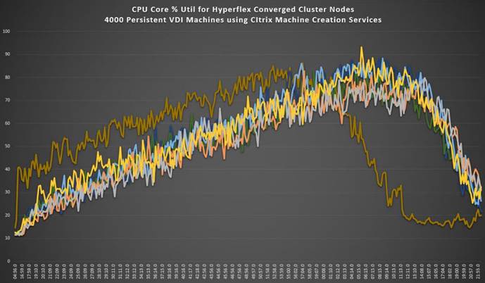
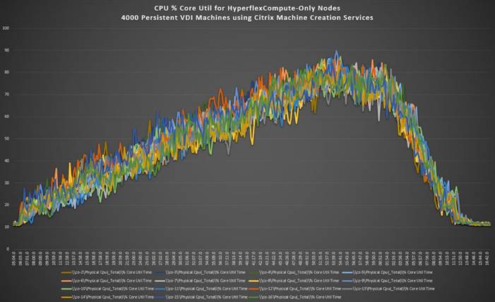
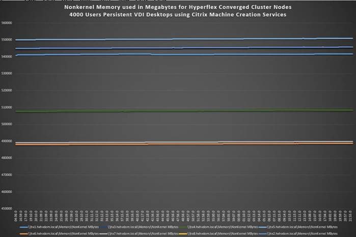
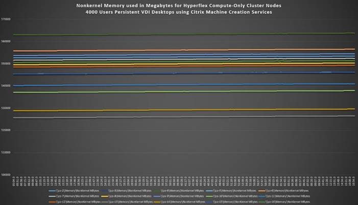
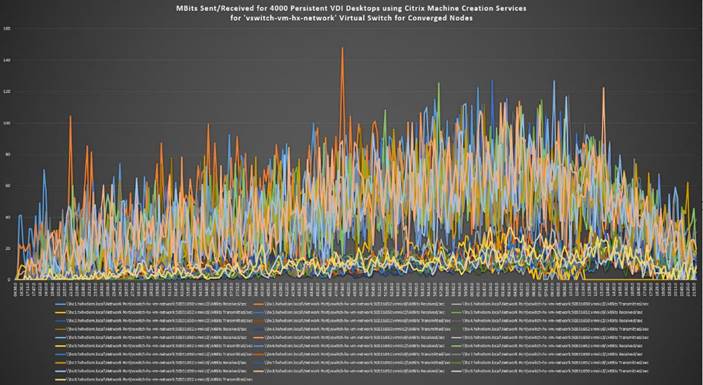
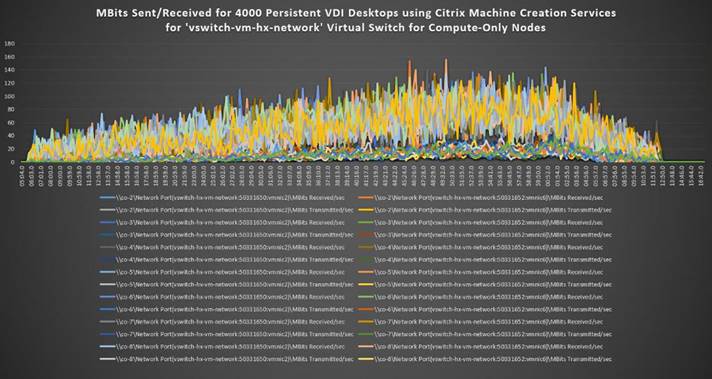
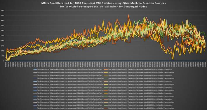
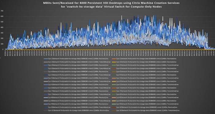
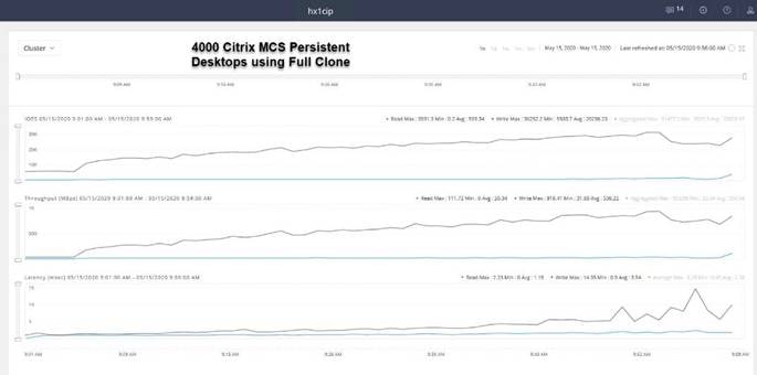
This Cisco HyperFlex solution addresses the urgent requirements of IT by delivering a platform that is cost effective and simple to deploy and manage. The architecture and approach used provides for a flexible and high-performance system with a familiar and consistent management model from Cisco. In addition, the solution offers numerous enterprise-class data management features to deliver the next-generation hyper-converged system.
Only Cisco offers the flexibility to add compute only nodes to a true hyper-converged cluster for compute intensive workloads like desktop virtualization. This translates to lower cost for the customer, since no hyper-convergence licensing is required for those nodes.
Delivering responsive, resilient, high-performance Citrix Virtual Desktops provisioned Microsoft Windows 10 Virtual Machines and Microsoft Windows Server for hosted Apps or desktops has many advantages for desktop virtualization administrators.
The solution is fully capable of supporting graphics accelerated workloads. Each Cisco HyperFlex HXAF240c M5 node and each Cisco UCS C240 M5 server can support up to two NVIDIA M10 or P40 cards. The Cisco UCS B200 M5 server supports up to two NVIDIA P6 cards for high density, high performance graphics workload support. See our Cisco Graphics White Paper for our fifth generation servers with NVIDIA GPUs and software for details on how to integrate this capability with Citrix Virtual Desktops.
Virtual desktop end-user experience, as measured by the Login VSI tool in benchmark mode, is outstanding with Intel Xeon scalable family processors and Cisco 2666Mhz memory. In fact, we have set a new industry standard in performance for Desktop Virtualization on a hyper-converged platform.
Jeff Nichols is a Cisco Unified Computing System architect, focusing on Virtual Desktop and Application solutions with extensive experience with Microsoft ESX/Hyper-V, Virtual Desktops, Virtual Apps and Microsoft Remote Desktop Services. He has expert product knowledge in application, desktop and server virtualization across all three major hypervisor platforms and supporting infrastructures including but not limited to Windows Active Directory and Group Policies, User Profiles, DNS, DHCP and major storage platforms.
Acknowledgements
For their support and contribution to the design, validation, and creation of this Cisco Validated Design, the author would like to acknowledge the following for their contribution and expertise that resulted in developing this document:
· Mike Brennan, Product Manager, Desktop Virtualization and Graphics Solutions, Cisco Systems, Inc.
· Brian Everitt, Technical Marketing Engineer, Computing Systems Product Group, Cisco Systems, Inc.