FlexPod Datacenter with Oracle 21c RAC on Cisco UCS X-Series M7 and NetApp AFF900 with NVMe/FC
Available Languages
Bias-Free Language
The documentation set for this product strives to use bias-free language. For the purposes of this documentation set, bias-free is defined as language that does not imply discrimination based on age, disability, gender, racial identity, ethnic identity, sexual orientation, socioeconomic status, and intersectionality. Exceptions may be present in the documentation due to language that is hardcoded in the user interfaces of the product software, language used based on RFP documentation, or language that is used by a referenced third-party product. Learn more about how Cisco is using Inclusive Language.
- US/Canada 800-553-2447
- Worldwide Support Phone Numbers
- All Tools
 Feedback
 Feedback
Published: December 2023

In partnership with:

About the Cisco Validated Design Program
The Cisco Validated Design (CVD) program consists of systems and solutions designed, tested, and documented to facilitate faster, more reliable, and more predictable customer deployments. For more information, go to: http://www.cisco.com/go/designzone.
Cisco Validated Designs include systems and solutions that are designed, tested, and documented to facilitate and improve customer deployments. The success of the FlexPod solution is driven through its ability to evolve and incorporate both technology and product innovations in the areas of management, compute, storage, and networking. This document explains the design details of incorporating the Cisco Unified Computing System (Cisco UCS) X-Series Modular Systems platform with end-to-end 100Gbps networking into a FlexPod Datacenter and the ability to monitor and manage FlexPod components from the cloud using Cisco Intersight.
The FlexPod Datacenter with NetApp All Flash AFF system is a converged infrastructure platform that combines best-of breed technologies from Cisco and NetApp into a powerful converged platform for enterprise applications. Cisco and NetApp work closely with Oracle to support the most demanding transactional and response-time-sensitive databases required by today’s businesses.
This Cisco Validated Design (CVD) describes the reference FlexPod Datacenter architecture using Cisco UCS X-Series and NetApp All Flash AFF Storage for deploying a highly available Oracle 21c Multitenant Real Application Clusters (RAC) Database environment. This document shows the hardware and software configuration of the components involved, results of various tests and offers implementation and best practices guidance using Cisco UCS X-Series Compute Servers, Cisco Fabric Interconnect Switches, Cisco Nexus Switches, Cisco MDS Switches and NetApp AFF Storage for implementing Oracle RAC Databases on NVMe/FC.
FlexPod Datacenter with end-to-end 100Gbps ethernet is configurable according to demand and usage. You can purchase the exact infrastructure you need for you current application requirements and can scale-up by adding more resources to the FlexPod system or scale-out by adding more FlexPod instances. By moving the management from the fabric interconnects into the cloud, the solution can respond to the speed and scale of your deployments with a constant stream of new capabilities delivered from Cisco Intersight software-as-a-service model at cloud-scale. For those that require management within a secure datacenter, Cisco Intersight is also offered as an on-site appliance with both connected and internet disconnected options.
This chapter contains the following:
· Audience
· Key Elements of a Datacenter FlexPod Solution
The Cisco Unified Computing System X-Series (Cisco UCSX) with Intersight Managed Mode (IMM) is a modular compute system, configured and managed from the cloud. It is designed to meet the needs of modern applications and to improve operational efficiency, agility, and scale through an adaptable, future-ready, modular design. The Cisco Intersight platform is a Software-as-a-Service (SaaS) infrastructure lifecycle management platform that delivers simplified configuration, deployment, maintenance, and support.
Powered by the Cisco Intersight cloud-operations platform, the Cisco UCS X-Series enables the next-generation cloud-operated FlexPod infrastructure that not only simplifies data-center management but also allows the infra-structure to adapt to the unpredictable needs of modern applications as well as traditional workloads.
This CVD describes how the Cisco UCS X-Series can be used in conjunction with NetApp AFF A900 All Flash storage systems to implement a mission-critical application such as an Oracle 21c RAC databases solution using modern SANs on NVMe over Fabrics (NVMe over Fibre-Channel or NVMe/FC).
The intended audience for this document includes, but is not limited to customers, field consultants, database administrators, IT architects, Oracle database architects, and sales engineers who want to deploy Oracle RAC 21c database solution on FlexPod Converged Infrastructure with NetApp clustered Data ONTAP and the Cisco UCS X-Series platform using Intersight Managed Mode (IMM) to deliver IT efficiency and enable IT innovation. A working knowledge of Oracle RAC Database, Linux, Storage technology, and Network is assumed but is not a prerequisite to read this document.
This document provides a step-by-step configuration and implementation guide for the FlexPod Datacenter with Cisco UCS X-Series Compute Servers, Cisco Fabric Interconnect Switches, Cisco MDS Switches, Cisco Nexus Switches and NetApp AFF Storage to deploy an Oracle RAC Database solution. Furthermore, it provides references for incorporating Cisco Intersight—managed Cisco UCS X-Series platform with end-to-end 100Gbps within a FlexPod Datacenter infrastructure. This document introduces various design elements and explains various considerations and best practices for a successful deployment.
The document also highlights the design and product requirements for integrating compute, network, and storage systems to Cisco Intersight to deliver a true cloud-based integrated approach to infrastructure management. The goal of this document is to build, validate and evaluate the performance of this FlexPod reference architecture while running various types of Oracle OLTP and OLAP workloads using various benchmarking exercises and showcase Oracle database server read latency, peak sustained throughput and IOPS under various stress tests.
The following design elements distinguish this version of FlexPod from previous models:
· Deploying and managing Cisco UCS X9508 chassis equipped with Cisco UCS X410c M7 compute nodes from the cloud using Cisco Intersight
· Support for the NVMe/FC on Cisco UCS and NetApp Storage
· Implementation of FC and NVMe/FC on the same architecture
· Integration of the 5th Generation Cisco UCS 6536 Fabric Interconnect into FlexPod Datacenter
· Integration of the 5th Generation Cisco UCS 15000 Series VICs into FlexPod Datacenter
· Integration of the Cisco UCSX-I-9108-100G Intelligent Fabric Module into the Cisco X-Series 9508 Chassis
· Implementation of end-to-end 100G network to optimize the I/O path between Oracle databases and the RAC Servers
· Validation of Oracle 21c Grid Infrastructure and 21c Databases
· Support for the release of NetApp ONTAP 9.12.1
Built on groundbreaking technology from NetApp and Cisco, the FlexPod converged infrastructure platform meets and exceeds the challenges of simplifying deployments for best-in-class data center infrastructure. FlexPod is a defined set of hardware and software that serves as an integrated foundation for both virtualized and non-virtualized solutions. Composed of pre-validated storage, networking, and server technologies, FlexPod is designed to increase IT responsiveness to organizational needs and reduce the cost of computing with maximum uptime and minimal risk. Simplifying the delivery of data center platforms gives enterprises an advantage in delivering new services and applications.
FlexPod provides the following differentiators:
· Flexible design with a broad range of reference architectures and validated designs.
· Elimination of costly, disruptive downtime through Cisco UCS and NetApp ONTAP.
· Leverage a pre-validated platform to minimize business disruption and improve IT agility and reduce deployment time from months to weeks.
· Cisco Validated Designs (CVDs) and NetApp Validated Architectures (NVAs) covering a variety of use cases.
Key Elements of a Datacenter FlexPod Solution
Cisco and NetApp have carefully validated and verified the FlexPod solution architecture and its many use cases while creating a portfolio of detailed documentation, information, and references to assist customers in transforming their data centers to this shared infrastructure model.
This reference FlexPod Datacenter architecture is built using the following infrastructure components for compute, network, and storage:
· Compute – Cisco UCS X-Series Chassis with Cisco UCS X410c M7 Blade Servers
· Network – Cisco UCS Fabric Interconnects, Cisco Nexus switches and Cisco MDS switches
· Storage – NetApp AFF All Flash Storage systems
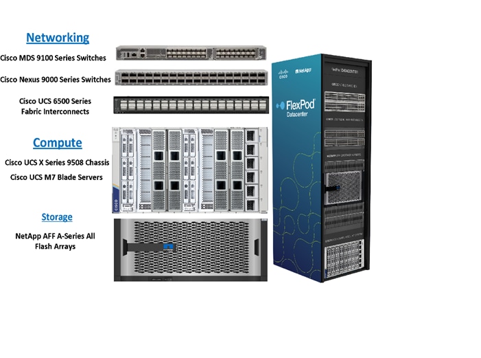
All FlexPod components have been integrated so you can deploy the solution quickly and economically while eliminating many of the risks associated with researching, designing, building, and deploying similar solutions from the foundation. One of the main benefits of FlexPod is its ability to maintain consistency at scale. Each of the component families (Cisco UCS, Cisco FI, Cisco Nexus, Cisco MDS and NetApp controllers) shown in the figure above offers platform and resource options to scale up or scale out the infrastructure while supporting the same features. The design is flexible enough that the networking, computing, and storage can fit in one data center rack or be deployed according to a customer's data center design. The reference architecture reinforces the "wire-once" strategy, because as additional storage is added to the architecture, no re-cabling is required from the hosts to the Cisco UCS fabric interconnect.
This FlexPod Datacenter solution for deploying Oracle RAC 21c Databases is built using the following hardware components:
· Fifth-generation Cisco UCS 6536 Fabric Interconnects to support 10/25/40/100GbE and Cisco Intersight platform to deploy, maintain and support UCS and FlexPod components.
· Two Cisco UCS X9508 Chassis with each chassis having two Cisco UCSX-I-9108-100G Intelligent Fabric Modules to deploy end to end 100GE connectivity.
· Total of four Cisco UCS X410c M7 Compute Nodes (2 Nodes per Chassis) with each node having one Cisco Virtual Interface Cards (VICs) 15231.
· High-speed Cisco NX-OS-based Cisco Nexus C9336C-FX2 switching design to support up to 100GE connectivity and Cisco MDS 9132T Fibre Channel Switches for Storage Networking
· NetApp AFF A900 end-to-end NVMe storage with 100GE/32GFC connectivity.
There are two modes to configure Cisco UCS, one is UCSM (UCS Managed) and the other is IMM (Intersight Managed Mode). This reference solution was deployed using Intersight Managed Mode (IMM). The best practices and setup recommendations are described later in this document.
Note: In this validated and deployed solution, the Cisco UCS X-Series is only supported in IMM mode.
This solution provides an end-to-end architecture with Cisco UCS and NetApp technologies to demonstrate the benefits for running Oracle RAC Database 21c environment with superior performance, scalability and high availability using NVMe over Fibre Channel (NVMe/FC).
Nonvolatile Memory Express (NVMe) is an optimized, high-performance, scalable interface designed to work with current and the next-generation NVM technologies. The NVMe interface is defined to enable host software to communicate with nonvolatile memory over PCI Express (PCIe). It was designed from the ground up for low-latency solid state media, eliminating many of the bottlenecks seen in the legacy protocols for running enterprise applications. NVMe devices are connected to the PCIe bus inside a server. NVMe-oF extends the high-performance and low-latency benefits of NVMe across network fabrics that connect servers and storage. NVMe-oF takes the lightweight and streamlined NVMe command set, and the more efficient queueing model, and replaces the PCIe transport with alternate transports, like Fibre Channel, RDMA over Converged Ethernet (RoCE v2), TCP.
NVMe over Fibre Channel (NVMe/FC) is implemented through the Fibre Channel NVMe (FC-NVMe) standard which is designed to enable NVMe based message commands to transfer data and status information between a host computer and a target storage subsystem over a Fibre Channel network fabric. FC-NVMe simplifies the NVMe command sets into basic FCP instructions. Since the Fibre Channel is designed for storage traffic, functionality such as discovery, management and end-to-end qualification of equipment is built into the system.
Most high-performance latency sensitive applications and workloads are running on FCP today. Since the NVMe/FC and Fibre Channel networks use the same underlying transport protocol (FCP), they can use common hardware components. It’s even possible to use the same switches, cables, and ONTAP target port to communicate with both protocols at the same time. The ability to use either protocol by itself or both at the same time on the same hardware makes transitioning from FCP to NVMe/FC both simple and seamless.
Large-scale block flash-based storage environments that use Fibre Channel are the most likely to adopt NVMe over FC. FC-NVMe offers the same structure, predictability, and reliability characteristics for NVMe-oF that Fibre Channel does for SCSI. Plus, NVMe-oF traffic and traditional SCSI-based traffic can run simultaneously on the same FC fabric.
This FlexPod solution showcases the Cisco UCS System with NetApp AFF Storage Array running on NVMe over FibreChannel (NVMe/FC) which can provide efficiency and performance of NVMe, and the benefits of all-flash robust scale out storage system that combines low-latency performance with comprehensive data management, built-in efficiencies, integrated data protection, multiprotocol support, and nondisruptive operations.
Figure 1 shows the architecture diagram of the FlexPod components to deploy a four node Oracle RAC 21c Database solution on NVMe/FC. This reference design is a typical network configuration that can be deployed in a customer's environment.
Figure 1. FlexPod components architecture
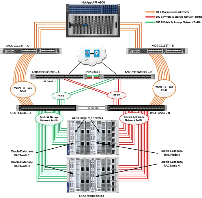
As shown in Figure 1, a pair of Cisco UCS 6536 Fabric Interconnects (FI) carries both storage and network traffic from the Cisco UCS X410c M7 server with the help of Cisco Nexus 9336C-FX2 switches and Cisco MDS 9132T switches. The Fabric Interconnects and the Cisco Nexus Switches are clustered with the peer link between them to provide high availability.
As illustrated in Figure 1, 16 (8 x 100G link per chassis) links from the blade server chassis go to Fabric Interconnect – A. Similarly, 16 (8 x 100G link per chassis) links from the blade server chassis go to Fabric Interconnect – B. Fabric Interconnect – A links are used for Oracle Public Network Traffic (VLAN-134) and Storage Network Traffic (VSAN 151) shown as green lines while Fabric Interconnect – B links are used for Oracle Private Interconnect Traffic (VLAN 10) and Storage Network Traffic (VSAN 152) shown as red lines. Two virtual Port-Channels (vPCs) are configured to provide public network and private network traffic paths for the server blades to northbound Nexus switches.
FC and NVMe/FC Storage access from both Fabric Interconnects to MDS Switches and NetApp Storage Array are shown as orange lines. Eight 32Gb links are connected from FI – A to MDS – A Switch. Similarly, eight 32Gb links are connected from FI – B to MDS – B Switch. The NetApp Storage AFF A900 has eight active FC connections that go to the Cisco MDS Switches. Four FC ports are connected to MDS-A, and the other four FC ports are connected to MDS-B Switch.
The NetApp Controller CT1 and Controller CT2 SAN ports 9a and 9c are connected to MDS – A Switch while the Controller CT1 and Controller CT2 SAN ports 9b and 9d are connected to MDS – B Switch. Also, two FC Port-Channels (PC) are configured (vPC 41 & vPC 42) to provide storage network paths from the server blades to storage array. Each port-channel has VSANs (VSAN 151 & VSAN 152) created for application and storage network data access.
Note: For the Oracle RAC configuration on Cisco Unified Computing System, we recommend keeping all private interconnect network traffic local on a single Fabric interconnect. In this case, the private traffic will stay local to that fabric interconnect and will not be routed through the northbound network switch. This way all the inter server blade (or RAC node private) communications will be resolved locally at the fabric interconnects and this significantly reduces latency for Oracle Cache Fusion traffic.
Additional 1Gb management connections are needed for an out-of-band network switch that is apart from this FlexPod infrastructure. Each Cisco UCS FI, Cisco MDS and Cisco Nexus switch is connected to the out-of-band network switch, and each NetApp AFF controller also has two connections to the out-of-band network switch.
Although this is the base design, each of the components can be scaled easily to support specific business requirements. For example, more servers or even blade chassis can be deployed to increase compute capacity, additional disk shelves can be deployed to improve I/O capability and throughput, and special hardware or software features can be added to introduce new features. This document guides you through the detailed steps for deploying the base architecture, as shown in Figure 1. These procedures cover everything from physical cabling to network, compute, and storage device configurations.
This section describes the hardware and software components used to deploy a four node Oracle RAC 21c Database Solution on this architecture.
The inventory of the components used in this solution architecture is listed in Table 1.
Table 1. Table for Hardware Inventory and Bill of Material
| Name |
Model/Product ID |
Description |
Quantity |
| Cisco UCS X Blade Server Chassis |
UCSX-9508 |
Cisco UCS X Series Blade Server Chassis, 7RU which can house a combination of compute nodes and a pool of future I/O resources that may include GPU accelerators, disk storage, and nonvolatile memory. |
2 |
| Cisco UCS 9108 100G IFM (Intelligent Fabric Module) |
UCSX-I-9108-100G |
Cisco UCS 9108 100G IFM connects the I/O fabric between the Cisco UCS X9508 Chassis and 6536 Fabric Interconnects 800 Gb/s (8x100Gb/s) Port IO Module for compute nodes |
4 |
| Cisco UCS X410c M7 Compute Server |
UCSX-410c-M7 |
Cisco UCS X410c M7 4 Socket Blade Server (4x 4th Gen Intel Xeon Scalable Processors) |
4 |
| Cisco UCS VIC 15231 |
UCSX-ML-V5D200G |
Cisco UCS VIC 15231 2x100/200G mLOM for X Compute Node |
4 |
| Cisco UCS 6536 Fabric Interconnect |
UCS-FI-6536 |
Cisco UCS 6536 Fabric Interconnect providing both network connectivity and management capabilities for the system |
2 |
| Cisco MDS Switch |
DS-C9132T-8PMESK9 |
Cisco MDS 9132T 32-Gbps 32-Port Fibre Channel Switch |
2 |
| Cisco Nexus Switch |
N9K-9336C-FX2 |
Cisco Nexus 9336C-FX2 Switch |
2 |
| NetApp AFF Storage |
AFF A900 |
NetApp AFF A-Series All Flash Arrays with NS224 NSM Disk Shelf Module |
1 |
Note: In this solution design, we used 4 identical Cisco UCS X410c M7 Blade Servers to configure the Red Hat Linux 8.7 Operating system and then deploy a 4 node Oracle RAC Database. The Cisco UCS X410c M7 Server configuration is listed in Table 2.
Table 2. Cisco UCS X410c M7 Compute Server Configuration
| Cisco UCS X410c M7 Server Configuration |
|
|
| Processor |
4 x Intel(R) Xeon(R) Platinum 8450H CPU @ 2GHz 250W 28C 75MB Cache (4 x 28 CPU Cores = 112 Core Total) |
PID - UCS-CPU-I8450H |
| Memory |
16 x Samsung 32GB DDR5-4800-MHz (512 GB) |
PID - UCS-MRX32G1RE1 |
| VIC 15231 |
Cisco UCS VIC 15231 Blade Server MLOM (200G for compute node) (2x100G through each fabric) |
PID - UCSX-ML-V5D200G |
Table 3. vNIC and vHBA Configured on each Linux Host
| vNIC Details |
|
| vNIC 0 (eth0) |
Management and Public Network Traffic Interface for Oracle RAC. MTU = 1500 |
| vNIC 1 (eth1) |
Private Server-to-Server Network (Cache Fusion) Traffic Interface for Oracle RAC. MTU = 9000 |
| vHBA0 |
FC Network Traffic & Boot from SAN through MDS-A Switch |
| vHBA1 |
FC Network Traffic & Boot from SAN through MDS-B Switch |
| vHBA2 |
NVMe/FC Network Traffic (Oracle RAC Storage Traffic) through MDS-A Switch |
| vHBA3 |
NVMe/FC Network Traffic (Oracle RAC Storage Traffic) through MDS-B Switch |
| vHBA4 |
NVMe/FC Network Traffic (Oracle RAC Storage Traffic) through MDS-A Switch |
| vHBA5 |
NVMe/FC Network Traffic (Oracle RAC Storage Traffic) through MDS-B Switch |
| vHBA6 |
NVMe/FC Network Traffic (Oracle RAC Storage Traffic) through MDS-A Switch |
| vHBA7 |
NVMe/FC Network Traffic (Oracle RAC Storage Traffic) through MDS-B Switch |
| vHBA8 |
NVMe/FC Network Traffic (Oracle RAC Storage Traffic) through MDS-A Switch |
| vHBA9 |
NVMe/FC Network Traffic (Oracle RAC Storage Traffic) through MDS-B Switch |
Note: For this solution, we configured 2 VLANs to carry public and private network traffic as well as two VSANs to carry FC and NVMe/FC storage traffic as listed in Table 4.
Table 4. VLAN and VSAN Configuration
| VLAN Configuration |
||
| VLAN |
||
| Name |
ID |
Description |
| Default VLAN |
1 |
Native VLAN |
| Public VLAN |
134 |
VLAN for Public Network Traffic |
| Private VLAN |
10 |
VLAN for Private Network Traffic |
| VSAN |
||
| Name |
ID |
Description |
| VSAN-A |
151 |
FC and NVMe/FC Network Traffic through for Fabric Interconnect A |
| VSAN-B |
152 |
FC and NVMe/FC Network Traffic through for Fabric Interconnect B |
This FlexPod solution consists of NetApp All Flash AFF Series Storage as listed in Table 5.
Table 5. NetApp AFF A900 Storage Configuration
| Storage Components |
Description |
| AFF A900 Flash Array |
NetApp All Flash AFF A900 Storage Array (24 x 3.49 TB NVMe SSD Drives) |
| NSM 100 Disk Shelf |
NetApp Disk Shelf NS224NSM100 Expansion Storage Shelf 24 x 3.84 TB NVMe SSD Drives (X4011WBORA3T8NTF)
|
| Capacity |
72.9 TB |
| Connectivity |
8 x 32 Gb/s redundant FC, NVMe/FC 1 Gb/s redundant Ethernet (Management port) |
| Physical |
10 Rack Units |
Table 6. Software and Firmware Revisions
| Software and Firmware |
Version |
| Cisco UCS FI 6536 |
Bundle Version 4.2(3e) or NX-OS Version – 9.3(5)I42(3d) Image Name - intersight-ucs-infra-5gfi.4.2.3e.bin |
| Cisco UCS X410c M7 Server |
5.2(0.230041) Image Name - intersight-ucs-server-410c-m7.5.2.0.230041.bin |
| Cisco UCS Adapter VIC 15231 |
5.3(2.32) |
| Cisco eNIC (Cisco VIC Ethernet NIC Driver) (modinfo enic) |
4.5.0.7-939.23 (kmod-enic-4.5.0.7-939.23.rhel8u7_4.18.0_425.3.1.x86_64) |
| Cisco fNIC (Cisco VIC FC HBA Driver) (modinfo fnic) |
2.0.0.90-252.0 (kmod-fnic-2.0.0.90-252.0.rhel8u7.x86_64) |
| Red Hat Enterprise Linux Server |
Red Hat Enterprise Linux release 8.7 (Kerel - 4.18.0-425.3.1.el8.x86_64) |
| Oracle Database 21c Grid Infrastructure for Linux x86-64 |
21.3.0.0.0 |
| Oracle Database 21c Enterprise Edition for Linux x86-64 |
21.3.0.0.0 |
| Cisco Nexus 9336C-FX2 NXOS |
NXOS System Version - 9.3(3) & BIOS Version – 05.40 |
| Cisco MDS 9132T Software |
System Version - 9.3(2) & BIOS Version - 1.43.0 |
| NetApp Storage AFF A900 |
ONTAP 9.12.1P4 |
| NetApp NS224NSM100 Disk Shelf |
NSM100:0210 |
| FIO |
fio-3.19-3.el8.x86_64 |
| Oracle Swingbench |
2.7 |
| SLOB |
2.5.4.0 |
Solution Configuration
This chapter contains the following:
· Cisco Nexus Switch Configuration
· Cisco UCS X-Series Configuration – Intersight Managed Mode (IMM)
· Cisco MDS Switch Configuration
· NetApp AFF A900 Storage Configuration
Cisco Nexus Switch Configuration
This section details the high-level steps to configure Cisco Nexus Switches.
Figure 2 illustrates the high-level overview and steps to configure various components to deploy and test the Oracle RAC Database 21c for this FlexPod reference architecture.
Figure 2. Cisco Nexus Switch configuration architecture
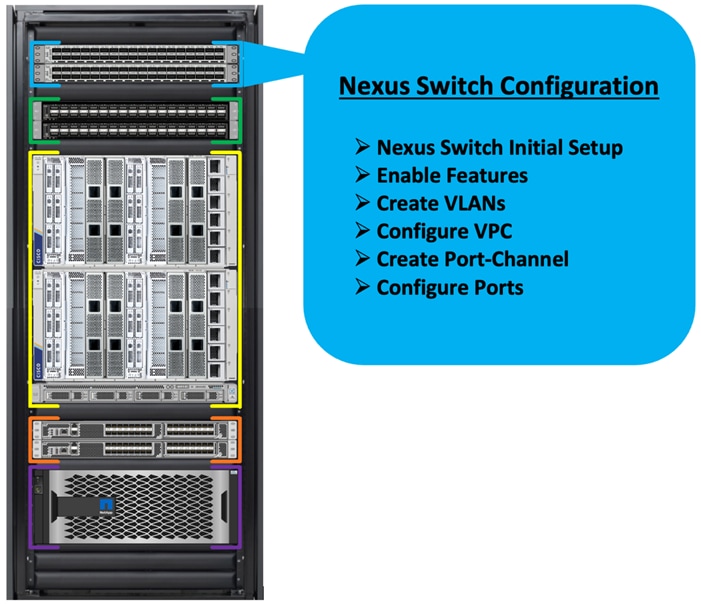
The following procedures describe how to configure the Cisco Nexus switches to use in a base FlexPod environment. This procedure assumes you’re using Cisco Nexus 9336C-FX2 switches deployed with the 100Gb end-to-end topology.
Note: On initial boot and connection to the serial or console port of the switch, the NX-OS setup should automatically start and attempt to enter Power on Auto Provisioning.
Procedure 1. Initial Setup for the Cisco Nexus A Switch
Step 1. To set up the initial configuration for the Cisco Nexus A Switch on <nexus-A-hostname>, run the following:
Abort Power on Auto Provisioning and continue with normal setup? (yes/no) [n]: yes
Do you want to enforce secure password standard (yes/no) [y]: Enter
Enter the password for "admin": <password>
Confirm the password for "admin": <password>
Would you like to enter the basic configuration dialog (yes/no): yes
Create another login account (yes/no) [n]: Enter
Configure read-only SNMP community string (yes/no) [n]: Enter
Configure read-write SNMP community string (yes/no) [n]: Enter
Enter the switch name: <nexus-A-hostname>
Continue with Out-of-band (mgmt0) management configuration? (yes/no) [y]: Enter
Mgmt0 IPv4 address: <nexus-A-mgmt0-ip>
Mgmt0 IPv4 netmask: <nexus-A-mgmt0-netmask>
Configure the default gateway? (yes/no) [y]: Enter
IPv4 address of the default gateway: <nexus-A-mgmt0-gw>
Configure advanced IP options? (yes/no) [n]: Enter
Enable the telnet service? (yes/no) [n]: Enter
Enable the ssh service? (yes/no) [y]: Enter
Type of ssh key you would like to generate (dsa/rsa) [rsa]: Enter
Number of rsa key bits <1024-2048> [1024]: Enter
Configure the ntp server? (yes/no) [n]: y
NTP server IPv4 address: <global-ntp-server-ip>
Configure default interface layer (L3/L2) [L3]: L2
Configure default switchport interface state (shut/noshut) [noshut]: Enter
Configure CoPP system profile (strict/moderate/lenient/dense/skip) [strict]: Enter
Would you like to edit the configuration? (yes/no) [n]: Enter
Cisco Nexus B Switch
Similarly, follow the steps in the procedure Initial Setup for the Cisco Nexus A Switch to setup the initial configuration for the Cisco Nexus B Switch and change the relevant switch hostname and management IP address according to your environment.
Procedure 1. Configure Global Settings
Configure the global setting on both Cisco Nexus Switches.
Step 1. Login as admin user into the Cisco Nexus Switch A and run the following commands to set the global configurations on switch A:
configure terminal
feature interface-vlan
feature hsrp
feature lacp
feature vpc
feature lldp
spanning-tree port type network default
spanning-tree port type edge bpduguard default
port-channel load-balance src-dst l4port
policy-map type network-qos jumbo
class type network-qos class-default
mtu 9216
system qos
service-policy type network-qos jumbo
vrf context management
ip route 0.0.0.0/0 10.29.134.1
copy run start
Step 2. Login as admin user into the Nexus Switch B and run the same above commands to set global configurations on Nexus Switch B.
Note: Make sure to run copy run start to save the configuration on each switch after the configuration is completed.
Procedure 2. VLANs Configuration
Create the necessary virtual local area networks (VLANs) on both Cisco Nexus switches.
Step 1. Login as admin user into the Cisco Nexus Switch A.
Step 2. Create VLAN 134 for Public Network Traffic, VLAN 10 for Private Network Traffic, and VLAN 21,22,23,24 for Storage Network Traffic.
configure terminal
vlan 134
name Oracle_RAC_Public_Traffic
no shutdown
vlan 10
name Oracle_RAC_Private_Traffic
no shutdown
interface Ethernet 1/29
description To-Management-Uplink-Switch
switchport access vlan 134
speed 1000
copy run start
Step 3. Login as admin user into the Nexus Switch B and similar way, create all the VLANs 134 for Oracle RAC Public Network Traffic and VLAN 10 for Oracle RAC Private Network Traffic.
Note: Make sure to run copy run start to save the configuration on each switch after the configuration is completed.
Virtual Port Channel (vPC) Summary for Network Traffic
A port channel bundles individual links into a channel group to create a single logical link that provides the aggregate bandwidth of up to eight physical links. If a member port within a port channel fails, traffic previously carried over the failed link switches to the remaining member ports within the port channel. Port channeling also load balances traffic across these physical interfaces. The port channel stays operational as long as at least one physical interface within the port channel is operational. Using port channels, Cisco NX-OS provides wider bandwidth, redundancy, and load balancing across the channels.
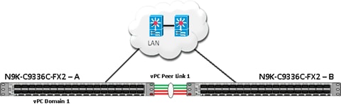
In the Cisco Nexus Switch topology, a single vPC feature is enabled to provide HA, faster convergence in the event of a failure, and greater throughput. The Cisco Nexus vPC configurations with the vPC domains and corresponding vPC names and IDs for Oracle Database Servers are listed in Table 7.
| vPC Domain |
vPC Name |
vPC ID |
| 1 |
Peer-Link |
1 |
| 51 |
vPC FI-A |
51 |
| 52 |
vPC FI-B |
52 |
As listed in Table 7, a single vPC domain with Domain ID 1 is created across two Nexus switches to define vPC members to carry specific VLAN network traffic. In this topology, we defined a total number of 3 vPCs.
vPC ID 1 is defined as Peer link communication between the two Cisco Nexus switches. vPC IDs 51 and 52 are configured for both Cisco UCS Fabric Interconnects.
Note: A port channel bundles up to eight individual interfaces into a group to provide increased bandwidth and redundancy.
Procedure 3. Create vPC Peer-Link
Note: For vPC 1 as Peer-link, we used interfaces 1 to 4 for Peer-Link. You may choose an appropriate number of ports based on your needs.
Create the necessary port channels between devices on both Cisco Nexus Switches.
Step 1. Login as admin user into the Cisco Nexus Switch A:
configure terminal
vpc domain 1
peer-keepalive destination 10.29.134.44 source 10.29.134.43
auto-recovery
interface port-channel 1
description vPC peer-link
switchport mode trunk
switchport trunk allowed vlan 1,10,134
spanning-tree port type network
vpc peer-link
no shut
interface Ethernet 1/1
description Peer link connected to ORA21C-N9K-B-Eth1/1
switchport mode trunk
switchport trunk allowed vlan 1,10,134
channel-group 1 mode active
no shut
interface Ethernet 1/2
description Peer link connected to ORA21C-N9K-B-Eth1/2
switchport mode trunk
switchport trunk allowed vlan 1,10,134
channel-group 1 mode active
no shut
interface Ethernet 1/3
description Peer link connected to ORA21C-N9K-B-Eth1/3
switchport mode trunk
switchport trunk allowed vlan 1,10,134
channel-group 1 mode active
no shut
interface Ethernet 1/4
description Peer link connected to ORA21C-N9K-B-Eth1/4
switchport mode trunk
switchport trunk allowed vlan 1,10,134
channel-group 1 mode active
no shut
exit
copy run start
Step 2. Login as admin user into the Cisco Nexus Switch B and repeat step 1 to configure the second Cisco Nexus Switch.
Note: Make sure to change the description of the interfaces and peer-keepalive destination and source IP addresses.
Step 3. Configure the vPC on the other Cisco Nexus switch. Login as admin for the Cisco Nexus Switch B:
configure terminal
vpc domain 1
peer-keepalive destination 10.29.134.43 source 10.29.134.44
auto-recovery
interface port-channel 1
description vPC peer-link
switchport mode trunk
switchport trunk allowed vlan 1,10,134
spanning-tree port type network
vpc peer-link
no shut
interface Ethernet 1/1
description Peer link connected to ORA21C-N9K-A-Eth1/1
switchport mode trunk
switchport trunk allowed vlan 1,10,134
channel-group 1 mode active
no shut
interface Ethernet 1/2
description Peer link connected to ORA21C-N9K-A-Eth1/2
switchport mode trunk
switchport trunk allowed vlan 1,10,134
channel-group 1 mode active
no shut
interface Ethernet 1/3
description Peer link connected to ORA21C-N9K-A-Eth1/3
switchport mode trunk
switchport trunk allowed vlan 1,10,134
channel-group 1 mode active
no shut
interface Ethernet 1/4
description Peer link connected to ORA21C-N9K-A-Eth1/4
switchport mode trunk
switchport trunk allowed vlan 1,10,134
channel-group 1 mode active
no shut
exit
copy run start
Create vPC Configuration between Cisco Nexus and Fabric Interconnect Switches
This section describes how to create and configure port channel 51 and 52 for network traffic between the Cisco Nexus and Fabric Interconnect Switches.
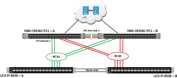
Table 8 lists the vPC IDs, allowed VLAN IDs, and ethernet uplink ports.
| vPC Description |
vPC ID |
Fabric Interconnects Ports |
Cisco Nexus Switch Ports |
Allowed VLANs |
| Port Channel FI-A |
51 |
FI-A Port 1/27 |
N9K-A Port 1/9 |
10,134 Note: VLAN 10 is needed for failover. |
| FI-A Port 1/28 |
N9K-A Port 1/10 |
|||
| FI-A Port 1/29 |
N9K-B Port 1/9 |
|||
| FI-A Port 1/30 |
N9K-B Port 1/10 |
|||
| Port Channel FI-B |
52 |
FI-B Port 1/27 |
N9K-A Port 1/11 |
10,134 Note: VLAN 134 is needed for failover. |
| FI-B Port 1/28 |
N9K-A Port 1/12 |
|||
| FI-B Port 1/29 |
N9K-B Port 1/11 |
|||
| FI-B Port 1/30 |
N9K-B Port 1/12 |
Verify the port connectivity on both Cisco Nexus Switches
Figure 3. Cisco Nexus A Connectivity
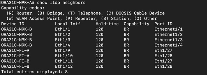
Figure 4. Cisco Nexus B Connectivity

Procedure 1. Configure the port channels on the Cisco Nexus Switches
Step 1. Login as admin user into Cisco Nexus Switch A and run the following commands:
configure terminal
interface port-channel 51
description connect to ORA21C-FI-A
switchport mode trunk
switchport trunk allowed vlan 1,10,134
spanning-tree port type edge trunk
mtu 9216
vpc 51
no shutdown
interface port-channel 52
description connect to ORA21C-FI-B
switchport mode trunk
switchport trunk allowed vlan 1,10,134
spanning-tree port type edge trunk
mtu 9216
vpc 52
no shutdown
interface Ethernet 1/9
description Fabric-Interconnect-A-27
switchport mode trunk
switchport trunk allowed vlan 1,10,134
spanning-tree port type edge trunk
mtu 9216
channel-group 51 mode active
no shutdown
interface Ethernet 1/10
description Fabric-Interconnect-A-28
switchport mode trunk
switchport trunk allowed vlan 1,10,134
spanning-tree port type edge trunk
mtu 9216
channel-group 51 mode active
no shutdown
interface Ethernet1/11
description Fabric-Interconnect-B-27
switchport mode trunk
switchport trunk allowed vlan 1,10,134
spanning-tree port type edge trunk
mtu 9216
channel-group 52 mode active
no shutdown
interface Ethernet 1/12
description Fabric-Interconnect-B-28
switchport mode trunk
switchport trunk allowed vlan 1,10,134
spanning-tree port type edge trunk
mtu 9216
channel-group 52 mode active
no shutdown
copy run start
Step 2. Login as admin user into Cisco Nexus Switch B and run the following commands to configure the second Cisco Nexus Switch:
configure terminal
interface port-channel 51
description connect to ORA21C-FI-A
switchport mode trunk
switchport trunk allowed vlan 1,10,134
spanning-tree port type edge trunk
mtu 9216
vpc 51
no shutdown
interface port-channel 52
description connect to ORA21C-FI-B
switchport mode trunk
switchport trunk allowed vlan 1,10,134
spanning-tree port type edge trunk
mtu 9216
vpc 52
no shutdown
interface Ethernet 1/9
description Fabric-Interconnect-A-29
switchport mode trunk
switchport trunk allowed vlan 1,10,134
spanning-tree port type edge trunk
mtu 9216
channel-group 51 mode active
no shutdown
interface Ethernet 1/10
description Fabric-Interconnect-A-30
switchport mode trunk
switchport trunk allowed vlan 1,10,134
spanning-tree port type edge trunk
mtu 9216
channel-group 51 mode active
no shutdown
interface Ethernet 1/11
description Fabric-Interconnect-B-29
switchport mode trunk
switchport trunk allowed vlan 1,10,134
spanning-tree port type edge trunk
mtu 9216
channel-group 52 mode active
no shutdown
interface Ethernet 1/12
description Fabric-Interconnect-B-30
switchport mode trunk
switchport trunk allowed vlan 1,10,134
spanning-tree port type edge trunk
mtu 9216
channel-group 52 mode active
no shutdown
copy run start
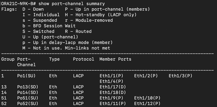
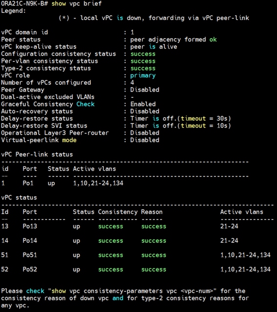
Verify All vPC Status
Procedure 1. Verify the status of all port-channels using Cisco Nexus Switches
Step 1. Cisco Nexus Switch A Port-Channel Summary:

Step 2. Cisco Nexus Switch B Port-Channel Summary:
Step 3. Cisco Nexus Switch A vPC Status:
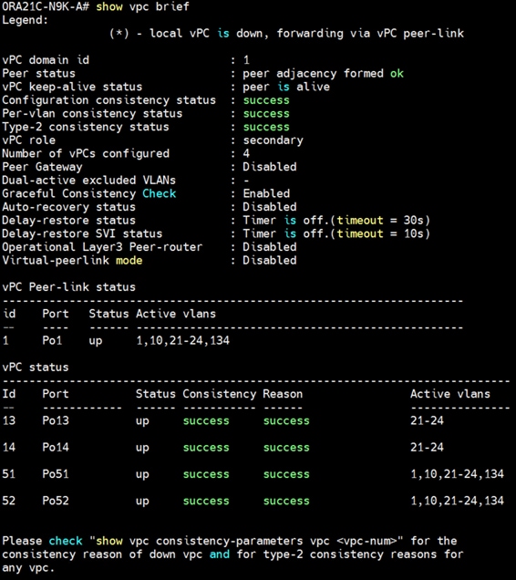
Step 4. Cisco Nexus Switch B vPC Status:
Cisco UCS X-Series Configuration – Intersight Managed Mode (IMM)
This section details the high-level steps for the Cisco UCS X-Series Configuration in Intersight Managed Mode.
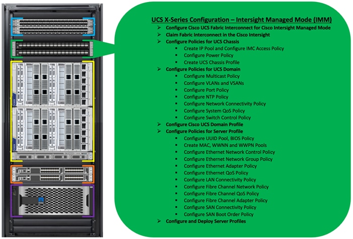
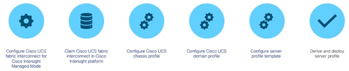
Cisco Intersight Managed Mode standardizes policy and operation management for Cisco UCS X-Series. The compute nodes in Cisco UCS X-Series are configured using server profiles defined in Cisco Intersight. These server profiles derive all the server characteristics from various policies and templates. At a high level, configuring Cisco UCS using Intersight Managed Mode consists of the steps shown in Figure 5.
Figure 5. Configuration Steps for Cisco Intersight Managed Mode
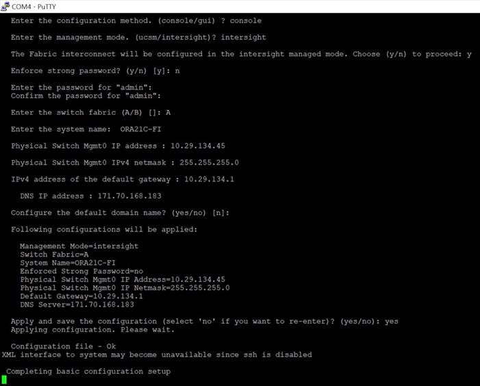
Procedure 1. Configure Cisco UCS Fabric Interconnect for Cisco Intersight Managed Mode
During the initial configuration, for the management mode, the configuration wizard enables you to choose whether to manage the fabric interconnect through Cisco UCS Manager or the Cisco Intersight platform. You can switch the management mode for the fabric interconnects between Cisco Intersight and Cisco UCS Manager at any time; however, Cisco UCS FIs must be set up in Intersight Managed Mode (IMM) for configuring the Cisco UCS X-Series system.
Step 1. Verify the following physical connections on the fabric interconnect:
· The management Ethernet port (mgmt0) is connected to an external hub, switch, or router.
· The L1 ports on both fabric interconnects are directly connected to each other.
· The L2 ports on both fabric interconnects are directly connected to each other.
Step 2. Connect to the console port on the first fabric interconnect and configure the first FI as shown below:
Step 3. Connect the console port on the second fabric interconnect B and configure it as shown below:
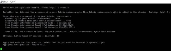
Step 4. After configuring both the FI management address, open a web browser and navigate to the Cisco UCS fabric interconnect management address as configured. If prompted to accept security certificates, accept, as necessary.
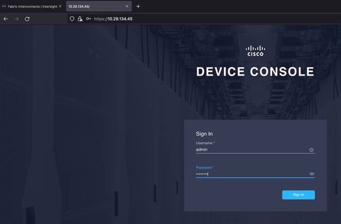
Step 5. Log into the device console for FI-A by entering your username and password.
Step 6. Go to the Device Connector tab and get the DEVICE ID and CLAIM Code as shown below:
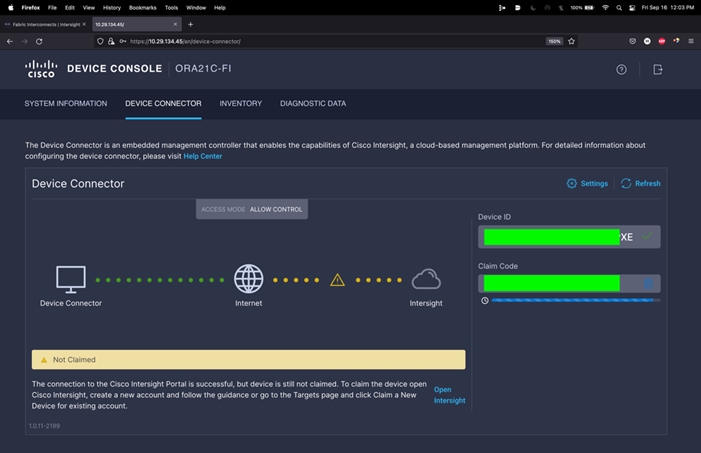
Procedure 2. Claim Fabric Interconnect in Cisco Intersight Platform
After setting up the Cisco UCS fabric interconnect for Cisco Intersight Managed Mode, FIs can be claimed to a new or an existing Cisco Intersight account. When a Cisco UCS Fabric Interconnect is successfully added to the Cisco Intersight platform, all future configuration steps are completed in the Cisco Intersight portal. After getting the device id and claim code of FI, go to https://intersight.com/.
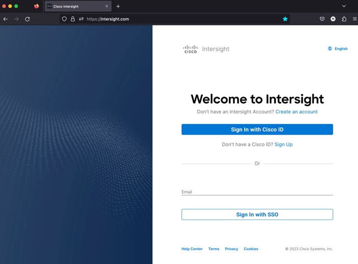
Step 7. Sign in with your Cisco ID or if you don’t have one, click Sing Up and setup your account.
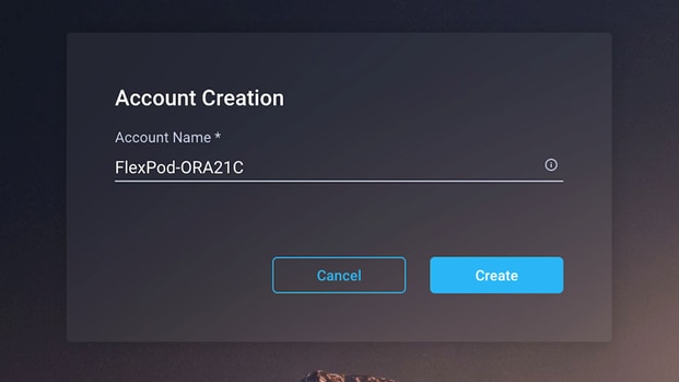
Note: We created the “FlexPod-ORA21C” account for this solution.
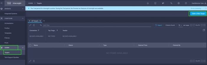
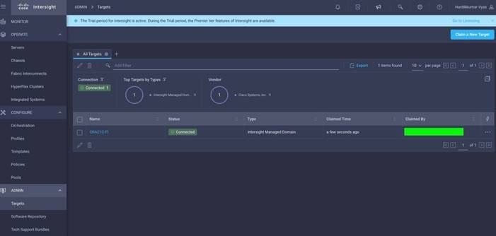
Step 8. After logging into your Cisco Intersight account, go to > ADMIN > Targets > Claim a New Target.
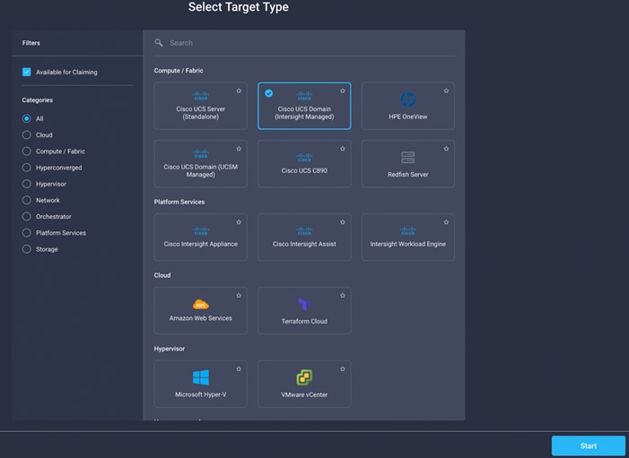
Step 9. For the Select Target Type, select “Cisco UCS Domain (Intersight Managed)” and click Start.
Step 10. Enter the Device ID and Claim Code which was previously captured. Click Claim to claim this domain in Cisco Intersight.
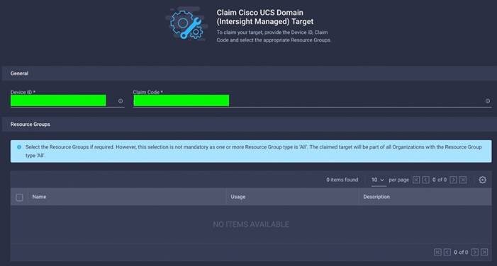
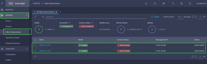
When you claim this domain, you can see both FIs under this domain and verify it’s under Intersight Managed Mode:
Procedure 3. Configure Policies for Cisco UCS Chassis
Note: For this solution, we configured Organization as “ORA21.” You will configure all the profile, pools, and policies under this common organization to better consolidate resources.
Step 1. To create Organization, go to Cisco Intersight > Settings > Organization and create depending upon your environment.
Note: We configured the IP Pool, IMC Access Policy, and Power Policy for the Cisco UCS Chassis profile as explained below.
Procedure 4. Create IP Pool
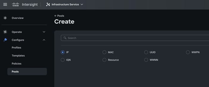
Step 1. To configure the IP Pool for the Cisco UCS Chassis profile, go to > Infrastructure Service > Configure > Pools > and then select “Create Pool” on the top right corner.
Step 2. Select option “IP” as shown below to create the IP Pool.
Step 3. In the IP Pool Create section, for Organization select “ORA21” and enter the Policy name “ORA-IP-Pool” and click Next.
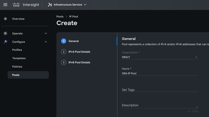
Step 4. Enter Netmask, Gateway, Primary DNS, IP Blocks and Size according to your environment and click Next.
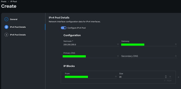
Note: For this solution, we did not configure the IPv6 Pool. Keep the Configure IPv6 Pool option disabled and click Create to create the IP Pool.
Procedure 5. Configure IMC Access Policy
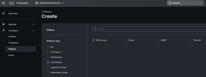
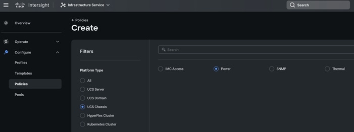
Step 1. To configure the IMC Access Policy for the Cisco UCS Chassis profile, go to > Infrastructure Service > Configure > Polices > and click Create Policy.
Step 2. Select the platform type “UCS Chassis” and select “IMC Access” policy.
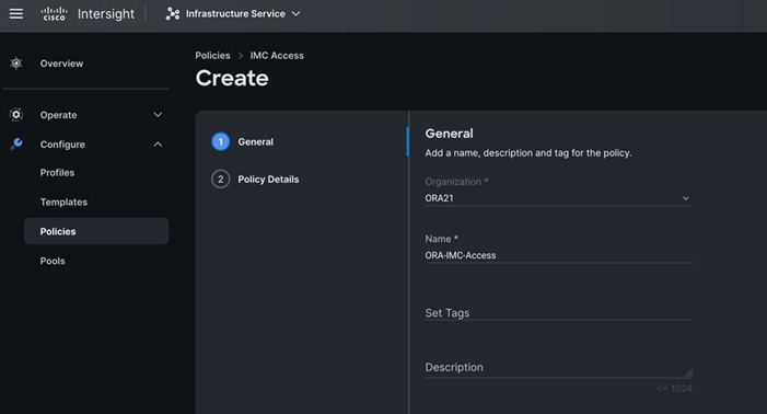
Step 3. In the IMC Access Create section, for Organization select “ORA21” and enter the Policy name “ORA-IMC-Access” and click Next.
Step 4. In the Policy Details section, enter the VLAN ID as 134 and select the IP Pool “ORA-IP-Pool.”
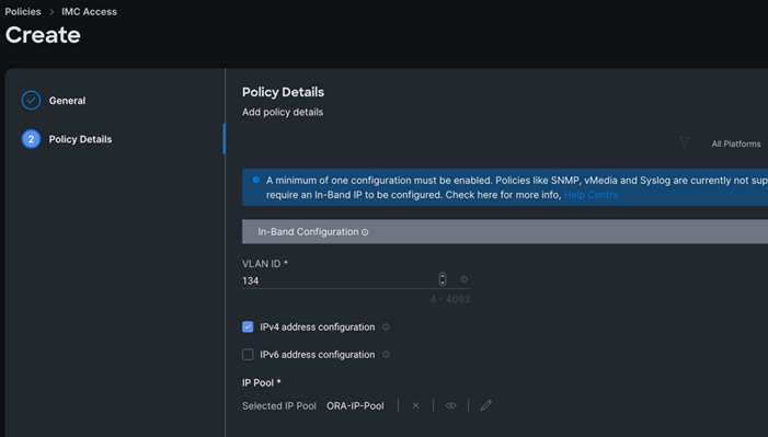
Step 5. Click Create to create this policy.
Procedure 6. Configure Power Policy
Step 1. To configure the Power Policy for the Cisco UCS Chassis profile, go to > Infrastructure Service > Configure > Polices > and click Create Policy.
Step 2. Select the platform type “UCS Chassis” and select “Power.”
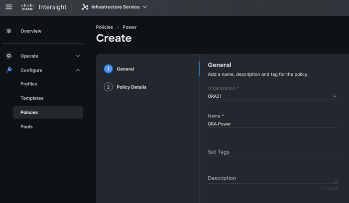
Step 3. In the Power Policy Create section, for Organization select “ORA21” and enter the Policy name “ORA-Power” and click Next.
Step 4. In the Policy Details section, for Power Redundancy select N+1 and turn off Power Save Mode.
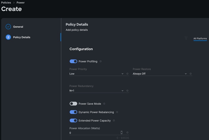
Step 5. Click Create to create this policy.
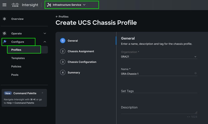
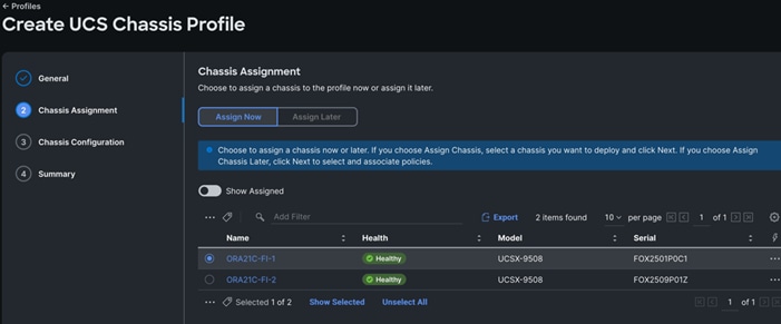
Procedure 7. Create Cisco UCS Chassis Profile
A Cisco UCS Chassis profile enables you to create and associate chassis policies to an Intersight Managed Mode (IMM) claimed chassis. When a chassis profile is associated with a chassis, Cisco Intersight automatically configures the chassis to match the configurations specified in the policies of the chassis profile. The chassis-related policies can be attached to the profile either at the time of creation or later. For more information, go to: https://intersight.com/help/saas/features/chassis/configure#chassis_profiles.
The chassis profile in a FlexPod is used to set the power policy for the chassis. By default, Cisco UCSX power supplies are configured in GRID mode, but the power policy can be utilized to set the power supplies in non-redundant or N+1/N+2 redundant modes
Step 1. To create a Cisco UCS Chassis Profile, go to Infrastructure Service > Configure > Profiles > UCS Chassis Domain Profiles tab > and click Create UCS Chassis Profile.
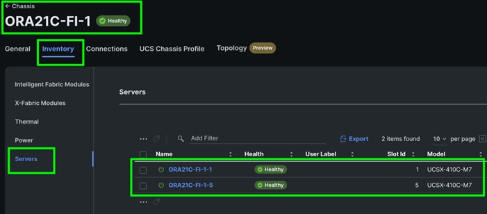
Step 2. In the Chassis Assignment menu, for the first chassis, click “ORA21C-FI-1” and click Next.
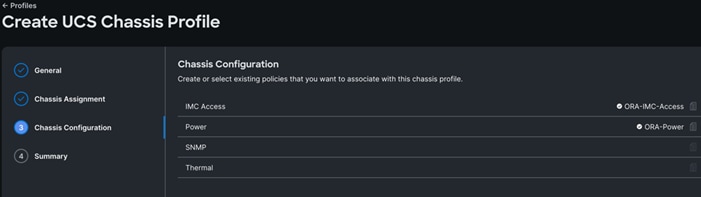
Step 3. In the Chassis configuration section, for the policy for IMC Access select “ORA-IMC-Access” and for the Power policy select “ORA-Power.”
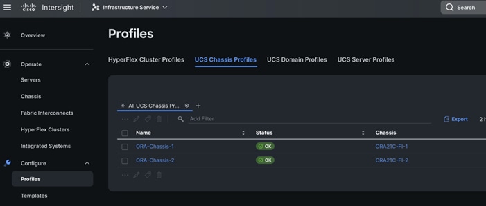
Step 4. Review the configuration settings summary for the Chassis Profile and click Deploy to create the Cisco UCS Chassis Profile for the first chassis.
Note: For this solution, we created two Chassis Profile (ORA-Chassis-1 and ORA-Chassis-2) and assigned to both the chassis as shown below:
Configure Policies for Cisco UCS Domain
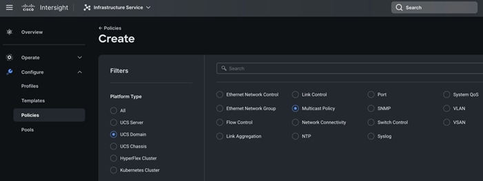
Procedure 1. Configure Multicast Policy
Step 1. To configure Multicast Policy for a Cisco UCS Domain profile, go to > Infrastructure Service > Configure > Polices > and click Create Policy. For the platform type select “UCS Domain” and for Policy, select “Multicast Policy.”
Step 2. In the Multicast Policy Create section, for the Organization select “ORA21” and for the Policy name “Multicast-ORA.” Click Next.
Step 3. In the Policy Details section, select Snooping State and Source IP Proxy State.
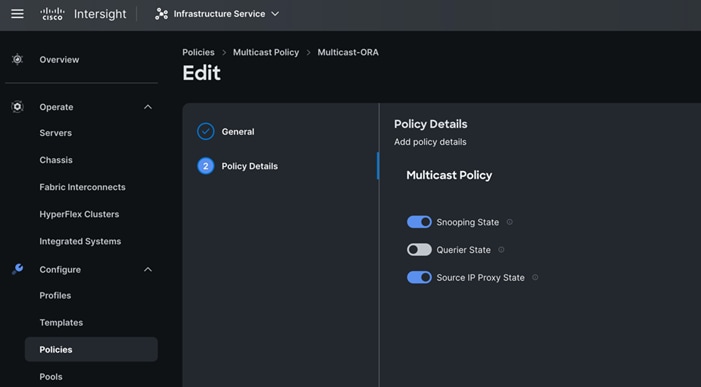
Step 4. Click Create to create this policy.
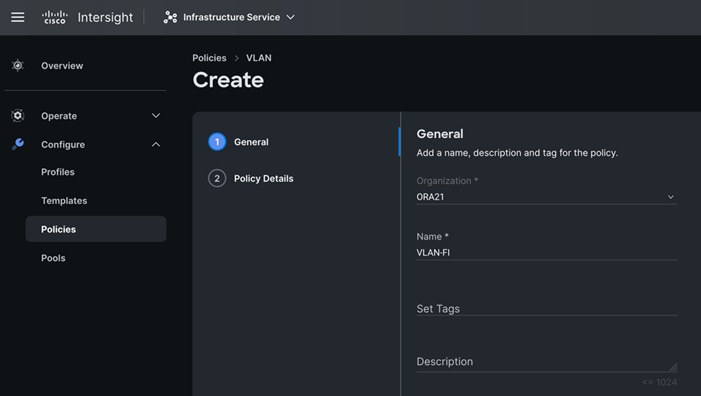
Procedure 2. Configure VLANs
Step 1. To configure the VLAN Policy for the Cisco UCS Domain profile, go to > Infrastructure Service > Configure > Polices > and click Create Policy. For the platform type select “UCS Domain” and for the Policy select “VLAN.”
Step 2. In the VLAN Policy Create section, for the Organization select “ORA21” and for the Policy name select “VLAN-FI.” Click Next.
Step 3. In the Policy Details section, to configure the individual VLANs, select "Add VLANs." Provide a name, VLAN ID for the VLAN and select the Multicast Policy as shown below:
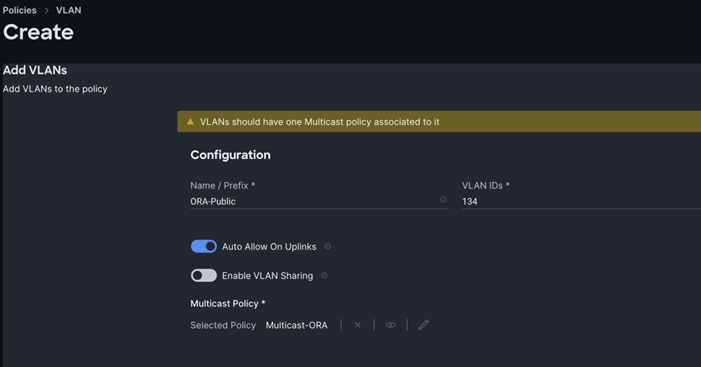
Step 4. Click Add to add this VLAN to the policy. Add another VLAN 10 and provide the names to various network traffic of this solution.
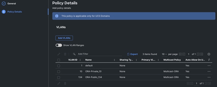
Step 5. Click Create to create this policy.
Procedure 3. Configure VSANs
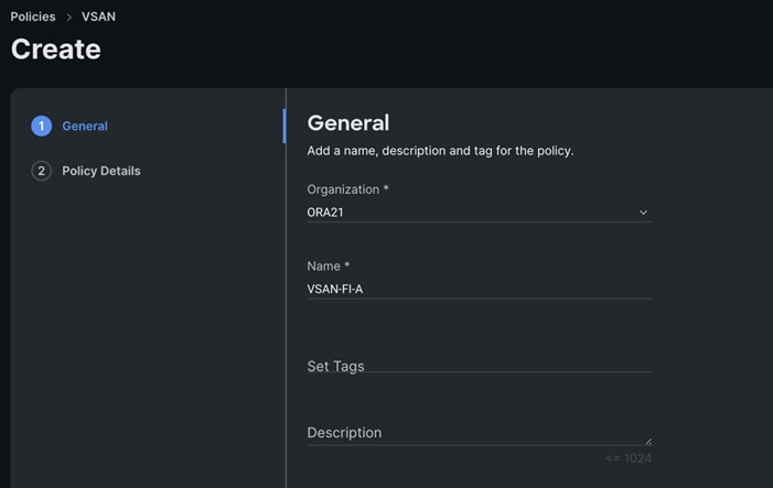
Step 1. To configure the VSAN Policy for the Cisco UCS Domain profile, go to > Infrastructure Service > Configure > Polices > and click Create Policy. For the platform type select “UCS Domain” and for the Policy select “VSAN.”
Step 2. In the VSAN Policy Create section, for the Organization select “ORA21” and for the Policy name select “VLAN-FI-A.” Click Next.
Step 3. In the Policy Details section, to configure the individual VSAN, select "Add VSAN." Provide a name, VSAN ID, FCoE VLAN ID and VSAN Scope for the VSAN on FI-A side as shown below:
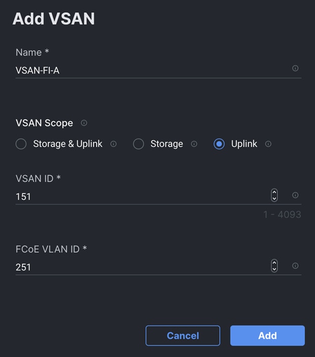
Note: Storage & Uplink VSAN scope allows you to provision SAN and Direct Attached Storage, using the fabric interconnect running in FC Switching mode. You have to externally provision the zones for the VSAN on upstream FC/FCoE switches. Storage VSAN scope allows you to connect and configure Direct Attached Storage, using the fabric interconnect running in FC Switching mode. You can configure local zones on this VSAN using FC Zone policies. All unmanaged zones in the fabric interconnect are cleared when this VSAN is configured for the first time. Do NOT configure this VSAN on upstream FC/FCoE switches.
Note: Uplink scope VSAN allows you to provision SAN connectivity using the Fabric Interconnect.
Step 4. Click Add to add this VSAN to the policy.
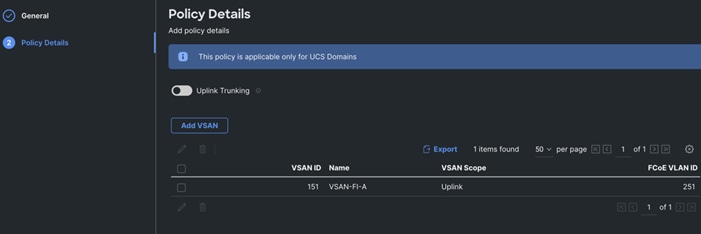
Step 5. Click Create to create this VSAN policy for FI-A.
Step 6. Configure VSAN policy for FI-B:
a. To configure the VSAN Policy for the Cisco UCS Domain profile, go to > Infrastructure Service > Configure > Polices > and click Create Policy. For the platform type select “UCS Domain” and for the Policy select “VSAN.”
b. In the VSAN Policy Create section, for the Organization select “ORA21” and for the Policy name select “VLAN-FI-B.” Click Next.
c. In the Policy Details section, to configure the individual VSAN, select "Add VSAN." Provide a name, VSAN ID, FCoE VLAN ID and VSAN Scope for the VSAN on FI-B side as shown below:

Step 7. Click Add to add this VSAN to the policy.
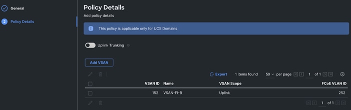
Step 8. Click Create to create this VSAN policy for FI-B.
Procedure 4. Configure Port Policy
Step 1. To configure the Port Policy for the Cisco UCS Domain profile, go to > Infrastructure Service > Configure > Polices > and click Create Policy. For the platform type select “UCS Domain” and for the policy, select “Port.”
Step 2. In the Port Policy Create section, for the Organization, select “ORA21”, for the policy name select “ORA-FI-A-Port-Policy” and for the Switch Model select "UCS-FI-6536.” Click Next.
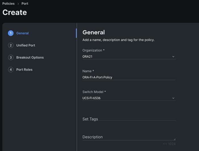
Note: We did not configure the Fibre Channel Ports for this solution. In the Unified Port section, leave it as default and click Next.
Note: We did not configure the Breakout options for this solution. Leave it as default and click Next.
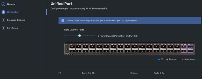
Step 3. In the Unified Port section, move the slider to right side as shown below. This changes Port 35 and Port 36 to FC port.
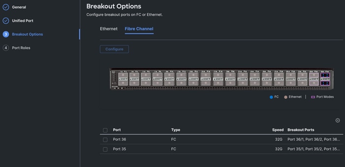
Step 4. In the Breakout Options section, go to Fibre Channel tab and select Port 35 and 36 and click Configure. Set Port 35 and 36 to “4x32G” and click Next.
Step 5. In the Port Role section, select port 1 to 16 and click Configure.
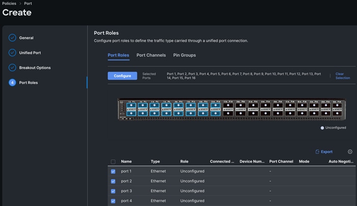
Step 6. In the Configure section, for Role select Server and keep the Auto Negotiation ON.
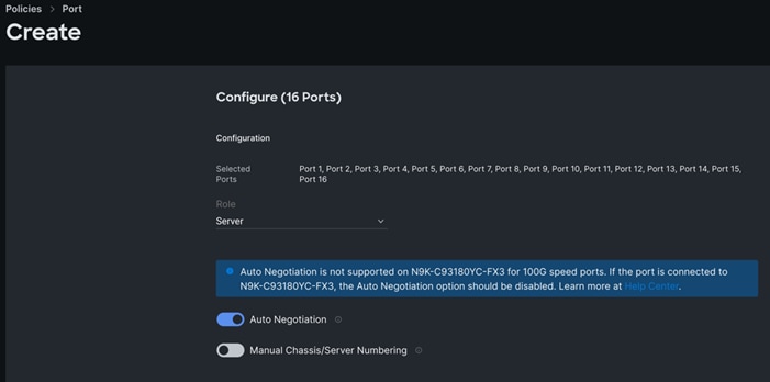
Step 7. Click SAVE to add this configuration for port roles.
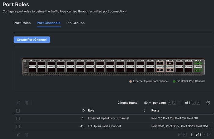
Step 8. Go to the Port Channels tab and select Port 27 to 30 and click Create Port Channel between FI-A and both Cisco Nexus Switches. In the Create Port Channel section, for Role select Ethernet Uplinks Port Channel, and for the Port Channel ID select 51 and select Auto for the Admin Speed.
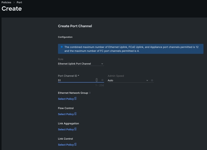
Step 9. Click SAVE to add this configuration for uplink port roles.
Step 10. Go to the Port Channels tab and now select Port 35/1 to 35/4 and 36/1 to 36/4. Click Create Port Channel between FI-A and Cisco MDS A Switch. In the Create Port Channel section, for Role select FC Uplink Port Channel, and for the Port Channel ID select 41 and enter 151 as VSAN ID.
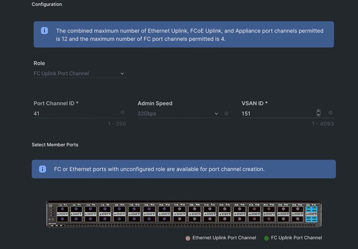
Step 11. Click SAVE to add this configuration for storage uplink port roles.
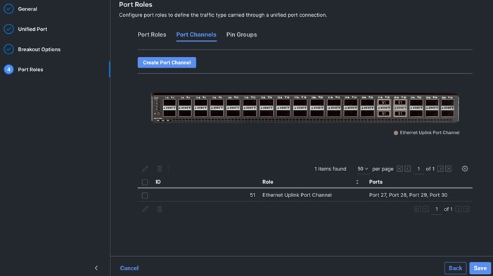
Step 12. Verify both the port channel as shown below:
Step 13. Click SAVE to complete this configuration for all the server ports and uplink port roles.
Note: We configured the FI-B ports and created a Port Policy for FI-B, “ORA-FI-B-Port-Policy.”
Note: In the FI-B port policy, we also configured unified ports as well as breakout options for 4x32G on port 35 and 36 for FC Traffic.
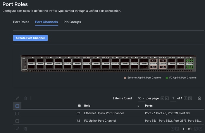
Note: As configured for FI-A, we configured the port policy for FI-B. For FI-B, configured port 1 to 16 for server ports, port 27 to 30 as the ethernet uplink port-channel ports and 35/1-35/4 to 36/1-36/4 ports as FC uplink Port channel ports.
Note: For FI-B, we configured Port-Channel ID as 52 for Ethernet Uplink Port Channel and Port-Channel ID as 42 for FC Uplink Port Channel as shown below:
This completes the Port Policy for FI-A and FI-B for Cisco UCS Domain profile.
Procedure 5. Configure NTP Policy
Step 1. To configure the NTP Policy for the Cisco UCS Domain profile, go to > Infrastructure Service > Configure > Polices > and click Create Policy. For the platform type select “UCS Domain” and for the policy select “NTP.”
Step 2. In the NTP Policy Create section, for the Organization select “ORA21” and for the policy name select “NTP-Policy.” Click Next.
Step 3. In the Policy Details section, select the option to enable the NTP Server and enter your NTP Server details as shown below.
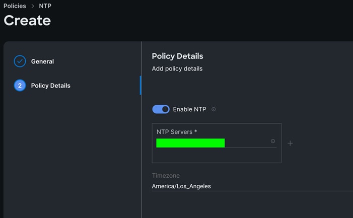
Step 4. Click Create.
Procedure 6. Configure Network Connectivity Policy
Step 1. To configure to Network Connectivity Policy for the Cisco UCS Domain profile, go to > Infrastructure Service > Configure > Polices > and click Create Policy. For the platform type select “UCS Domain” and for the policy select “Network Connectivity.”
Step 2. In the Network Connectivity Policy Create section, for the Organization select “ORA21” and for the policy name select “Network-Connectivity-Policy.” Click Next.
Step 3. In the Policy Details section, enter the IPv4 DNS Server information according to your environment details as shown below:
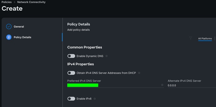
Step 4. Click Create.
Procedure 7. Configure System QoS Policy
Step 1. To configure the System QoS Policy for the Cisco UCS Domain profile, go to > Infrastructure Service > Configure > Polices > and click Create Policy. For the platform type select “UCS Domain” and for the policy select “System QoS.”
Step 2. In the System QoS Policy Create section, for the Organization select “ORA21” and for the policy name select “ORA-QoS.” Click Next.
Step 3. In the Policy Details section under Configure Priorities, select Best Effort and set the MTU size to 9216.
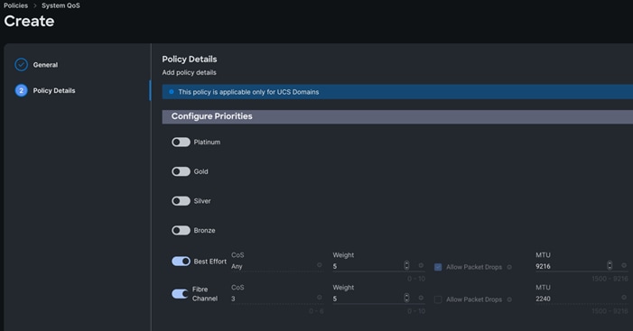
Step 4. Click Create.
Procedure 8. Configure Switch Control Policy
Step 1. To configure the Switch Control Policy for the UCS Domain profile, go to > Infrastructure Service > Configure > Polices > and click Create Policy. For the platform type select “UCS Domain” and for the policy select “Switch Control.”
Step 2. In the Switch Control Policy Create section, for the Organization select “ORA21” and for the policy name select “ORA-Switch-Control.” Click Next.
Step 3. In the Policy Details section, for the Switching Mode for Ethernet as well as FC, select and keep "End Host" Mode.
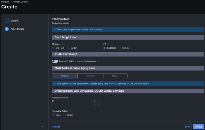
Step 4. Click Create to create this policy.
Configure Cisco UCS Domain Profile
With Cisco Intersight, a domain profile configures a fabric interconnect pair through reusable policies, allows for configuration of the ports and port channels, and configures the VLANs and VSANs in the network. It defines the characteristics of and configures ports on fabric interconnects. You can create a domain profile and associate it with a fabric interconnect domain. The domain-related policies can be attached to the profile either at the time of creation or later. One UCS Domain profile can be assigned to one fabric interconnect domain. For more information, go to: https://intersight.com/help/saas/features/fabric_interconnects/configure#domain_profile
Some of the characteristics of the Cisco UCS domain profile in the FlexPod environment are:
· A single domain profile (ORA-Domain) is created for the pair of Cisco UCS fabric interconnects.
· Unique port policies are defined for the two fabric interconnects.
· The VLAN configuration policy is common to the fabric interconnect pair because both fabric interconnects are configured for the same set of VLANs.
· The VSAN configuration policy is different to each of the fabric interconnects because both fabric interconnects are configured to carry separate storage traffic through separate VSANs.
· The Network Time Protocol (NTP), network connectivity, and system Quality-of-Service (QoS) policies are common to the fabric interconnect pair.
Procedure 1. Create a domain profile
Step 1. To create a domain profile, go to Infrastructure Service > Configure > Profiles > then go to the UCS Domain Profiles tab and click Create UCS Domain Profile.
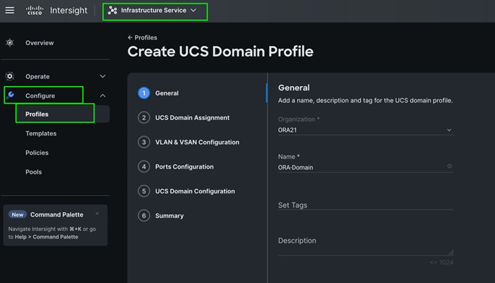
Step 2. For the domain profile name, enter “ORA-Domain” and for the Organization select what was previously configured. Click Next.
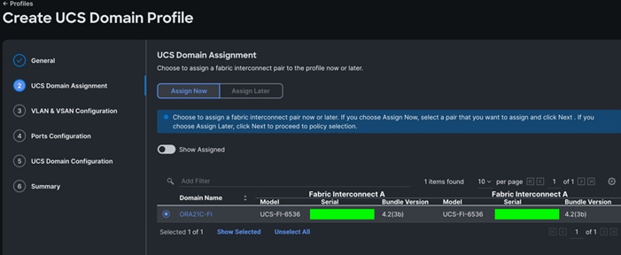
Step 3. In the UCS Domain Assignment menu, for the Domain Name select “ORA21C-FI” which was added previously into this domain and click Next.
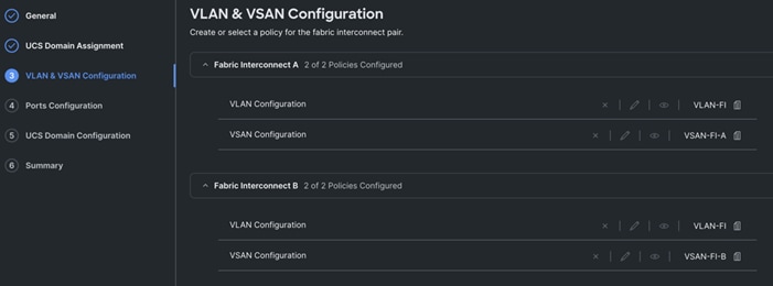
Step 4. In the VLAN & VSAN Configuration screen, for the VLAN Configuration for both FIs, select VLAN-FI. For the VSAN configuration for FI-A, select VSAN-FI-A and for FI-B select VSAN-FI-B that were configured in the previous section. Click Next.
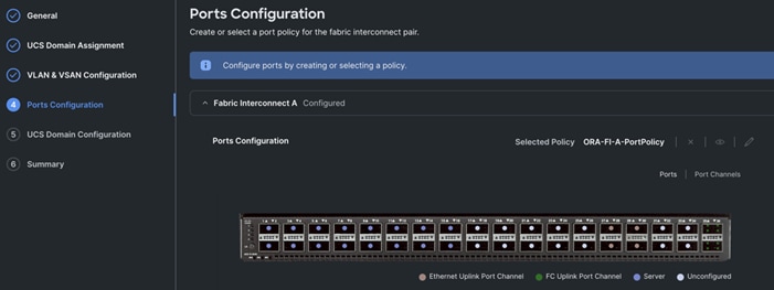
Step 5. In the Port Configuration section, for the Port Configuration Policy for FI-A select ORA-FI-A-PortPolicy. For the port configuration policy for FI-B select ORA-FI-B-PortPolicy.
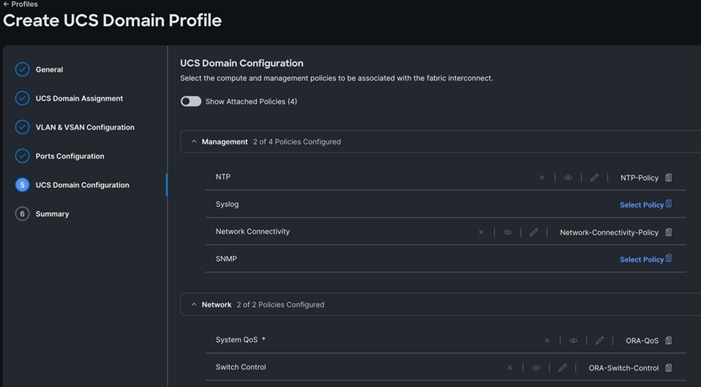
Step 6. In the UCS Domain Configuration section, select the policy for NTP, Network Connectivity, System QoS and Switch Control as shown below:
Step 7. In the Summary window, review the policies and click Deploy to create Domain Profile.
After the Cisco UCS domain profile has been successfully created and deployed, the policies including the port policies are pushed to the Cisco UCS fabric interconnects. The Cisco UCS domain profile can easily be cloned to install additional Cisco UCS systems. When cloning the Cisco UCS domain profile, the new Cisco UCS domains utilize the existing policies for the consistent deployment of additional Cisco UCS systems at scale.
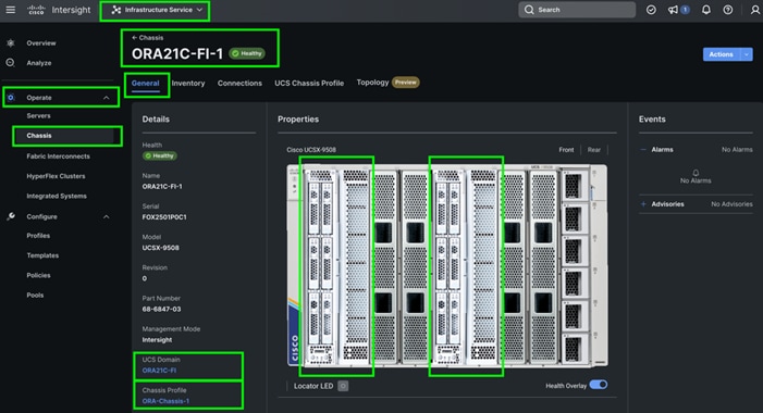
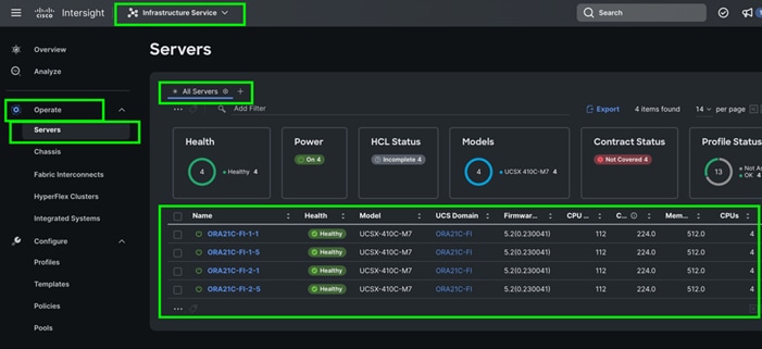
The Cisco UCS X9508 Chassis and Cisco UCS X410c M7 Compute Nodes are automatically discovered when the ports are successfully configured using the domain profile as shown below:
Step 8. After discovering the servers successfully, upgrade all server firmware through IMM to the supported release. To do this, check the box for All Servers and then click the ellipses and from the drop-down list, select Upgrade Firmware.
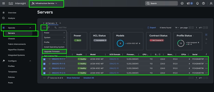
Step 9. In the Upgrade Firmware section, select all servers and click Next. In the Version section, for the supported firmware version release select “5.2(0.230041)” and click Next, then click Upgrade to upgrade the firmware on all servers simultaneously.
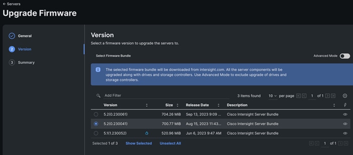
After the successful firmware upgrade, you can create a server profile template and a server profile for IMM configuration.
Configure Policies for Server Profile
A server profile enables resource management by simplifying policy alignment and server configuration. The server profile wizard groups the server policies into the following categories to provide a quick summary view of the policies that are attached to a profile:
· Compute Configuration: BIOS, Boot Order, and Virtual Media policies.
· Management Configuration: Certificate Management, IMC Access, IPMI (Intelligent Platform Management Interface) Over LAN, Local User, Serial Over LAN, SNMP (Simple Network Management Protocol), Syslog and Virtual KVM (Keyboard, Video, and Mouse).
· Storage Configuration: SD Card, Storage.
· Network Configuration: LAN connectivity and SAN connectivity policies.
Some of the characteristics of the server profile template for FlexPod are as follows:
· BIOS policy is created to specify various server parameters in accordance with FlexPod best practices.
· Boot order policy defines virtual media (KVM mapper DVD) and SAN boot through NetApp storage.
· IMC access policy defines the management IP address pool for KVM access.
· LAN connectivity policy is used to create two virtual network interface cards (vNICs) – One vNIC for Server Node Management and Public Network Traffic, second vNIC for Private Server-to-Server Network (Cache Fusion) Traffic Interface for Oracle RAC.
· SAN connectivity policy is used to create total 10 vHBA (2 vHBA for FC SAN Boot and 8 vHBA for NVMe FC Database traffic) per server to boot through FC SAN as well as run NVMe FC traffics on the same server node.
Procedure 1. Configure UUID Pool
Step 1. To create UUID Pool for a Cisco UCS, go to > Infrastructure Service > Configure > Pools > and click Create Pool. Select option UUID.
Step 2. In the UUID Pool Create section, for the Organization, select ORA21 and for the Policy name ORA-UUID. Click Next
Step 3. Select Prefix, UUID block and size according to your environment. and click Create.

Procedure 2. Configure BIOS Policy
Note: For more information, see “Performance Tuning Best Practices Guide for Cisco UCS M7 Platforms”
Note: For this specific database solution, we created a BIOS policy and used all “Platform Default” values.
Step 1. To create BIOS Policy, go to > Infrastructure Service > Configure > Policies > and select Platform type as UCS Server and select on BIOS and click on start.
Step 2. In the BIOS create general menu, for the Organization, select ORA21 and for the Policy name ORA-BIOS. Click Next
Step 3. Click Create to create the platform default BIOS policy.
Procedure 3. Create MAC Pool
Step 1. To configure a MAC Pool for a Cisco UCS Domain profile, go to > Infrastructure Service > Configure > Pools > and click Create Pool. Select option MAC to create MAC Pool.
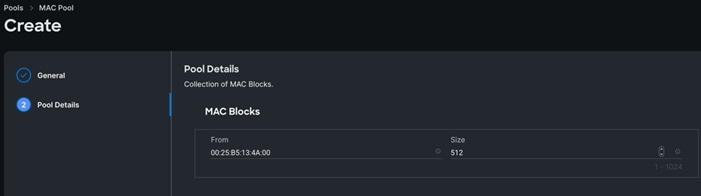
Step 2. In the MAC Pool Create section, for the Organization, select ORA21 and for the Policy name ORA-MAC-A. Click Next.
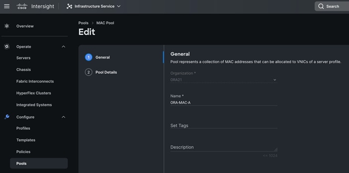
Step 3. Enter the MAC Blocks from and Size of the pool according to your environment and click Create.
Note: For this solution, we configured two MAC Pools. ORA-MAC-A for vNICs MAC Address VLAN 134 (public network traffic) on all servers through FI-A Side. ORA-MAC-B for vNICs MAC Address of VLAN 10 (private network traffic) on all servers through FI-B Side.
Step 4. Create a second MAC Pool to provide MAC addresses to all vNICs running on VLAN 10.
Step 5. Go to > Infrastructure Service > Configure > Pools > and click Create Pool. Select option MAC to create MAC Pool.
Step 6. In the MAC Pool Create section, for the Organization, select ORA21 and for the Policy name “ORA-MAC-B.” Click Next.
Step 7. Enter the MAC Blocks from and Size of the pool according to your environment and click Create.

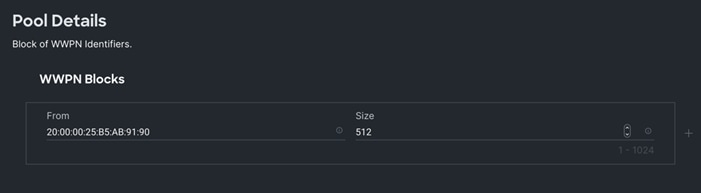
Procedure 4. Create WWNN and WWPN Pools
Step 1. To create WWNN Pool, go to > Infrastructure Service > Configure > Pools > and click Create Pool. Select option WWNN.
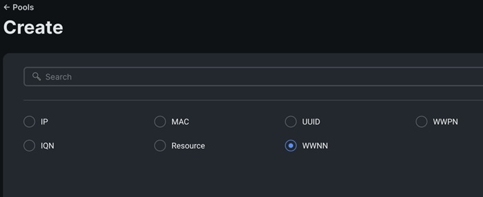
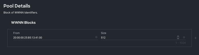
Step 2. In the WWNN Pool Create section, for the Organization select ORA21 and name it “WWNN-Pool.” Click Next.
Step 3. Add WWNN Block and Size of the pool according to your environment and click Create.
Step 4. Click Create to create this policy.
Step 5. Create WWPN Pool, go to > Infrastructure Service > Configure > Pools > and click Create Pool. Select option WWPN.
Step 6. In the WWPN Pool Create section, for the Organization select ORA21 and name it “WWPN-Pool.” Click Next.
Step 7. Add WWPN Block and Size of the pool according to your environment and click Create.
Step 8. Click Create to create this policy.
Procedure 5. Configure Ethernet Network Control Policy
Step 1. To configure the Ethernet Network Control Policy for the UCS server profile, go to > Infrastructure Service > Configure > Polices > and click Create Policy.
Step 2. For the platform type select UCS Server and for the policy select Ethernet Network Control.
Step 3. In the Switch Control Policy Create section, for the Organization select ORA21 and for the policy name enter “ORA-Eth-Network-Control.” Click Next.
Step 4. In the Policy Details section, keep the parameter as shown below:

Step 5. Click Create to create this policy.
Procedure 6. Configure Ethernet Network Group Policy
Note: We configured two Ethernet Network Groups to allow two different VLAN traffic for this solution.
Step 1. To configure the Ethernet Network Group Policy for the UCS server profile, go to > Infrastructure Service > Configure > Polices > and click Create Policy.
Step 2. For the platform type select UCS Server and for the policy select Ethernet Network Group.
Step 3. In the Switch Control Policy Create section, for the Organization select ORA21 and for the policy name enter “Eth-Network-134.” Click Next.
Step 4. In the Policy Details section, for the Allowed VLANs and Native VLAN enter 134 as shown below:
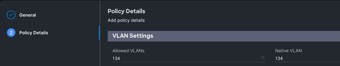
Step 5. Click Create to create this policy for VLAN 134.
Step 6. Create “Eth-Network-10” and add VLAN 10 for the Allowed VLANs and Native VLAN.
Note: For this solution, we used these Ethernet Network Group policies and applied them on different vNICs to carry individual VLAN traffic.
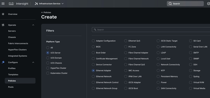
Procedure 7. Configure Ethernet Adapter Policy
Step 1. To configure the Ethernet Adapter Policy for the UCS Server profile, go to > Infrastructure Service > Configure > Polices > and click Create Policy.
Step 2. For the platform type select UCS Server and for the policy select Ethernet Adapter.
Step 3. In the Ethernet Adapter Configuration section, for the Organization select ORA21 and for the policy name enter ORA-Linux-Adapter.
Step 4. Select the Default Ethernet Adapter Configuration option and select Linux from the popup menu. Click Next.
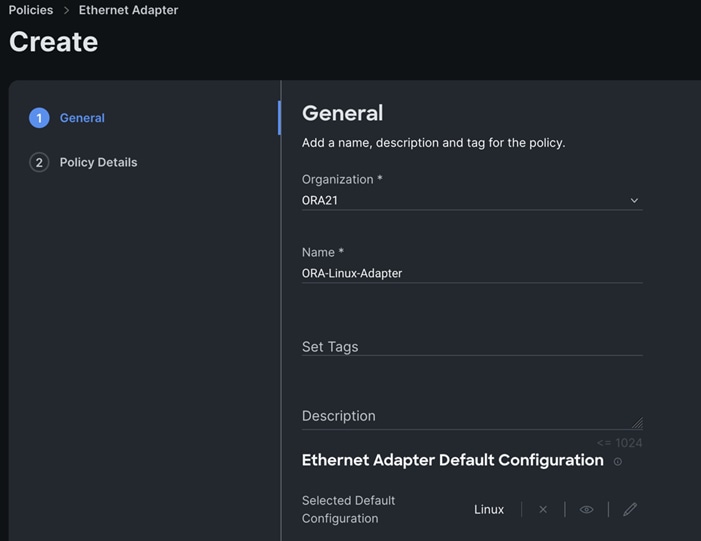
Step 5. In the Ethernet Adapter Configuration section, for the Organization select ORA21 and for the policy name enter “ORA-Linux-Adapter.” Select the Default Ethernet Adapter Configuration option and select Linux from the popup menu. Click Next.
Step 6. In the Policy Details section, for the recommended performance on the ethernet adapter, keep the “Interrupt Settings” parameter.
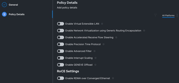
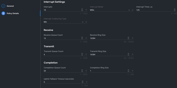
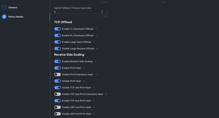
Step 7. Click Create to create this policy.
Procedure 8. Create Ethernet QoS Policy
Step 1. To configure the Ethernet QoS Policy for the UCS Server profile, go to > Infrastructure Service > Configure > Polices > and click Create Policy.
Step 2. For the platform type select UCS Server and for the policy select Ethernet QoS.
Step 3. In the Create Ethernet QoS Configuration section, for the Organization select ORA21 and for the policy name enter “ORA-Eth-QoS-1500” click Next.
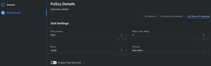
Step 4. Enter QoS Settings as shown below to configure 1500 MTU for management vNIC.

Step 5. Click Create to create this policy for vNIC0.
Step 6. Create another QoS policy for second vNIC running oracle private network and interconnect traffic.
Step 7. In the Create Ethernet QoS Configuration section, for the Organization select ORA21 and for the policy name enter “ORA-Eth-QoS-9000.” Click Next.
Step 8. Enter QoS Settings as shown below to configure 9000 MTU for oracle database private interconnect vNIC traffic.
Step 9. Click Create to create this policy for vNIC1.
Procedure 9. Configure LAN Connectivity Policy
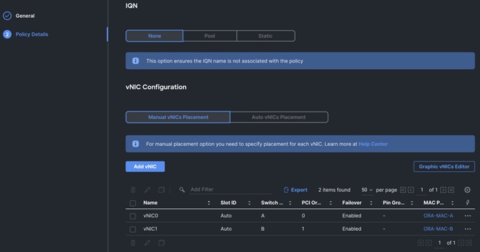
Two vNICs were configured per server as shown in Table 10.
| Name |
Switch ID |
PCI-Order |
MAC Pool |
Fail-Over |
| vNIC0 |
FI – A |
0 |
ORA-MAC-A |
Enabled |
| vNIC1 |
FI – B |
1 |
ORA-MAC-B |
Enabled |
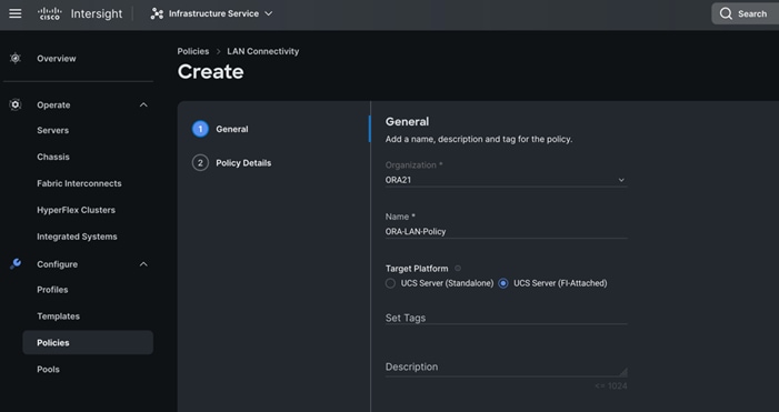
Step 1. Go to > Infrastructure Service > Configure > Polices > and click Create Policy. For the platform type select “UCS Server” and for the policy select “LAN Connectivity.”
Step 2. In the LAN Connectivity Policy Create section, for the Organization select ORA21,for the policy name enter “ORA-LAN-Policy” and for the Target Platform select UCS Server (FI-Attached). Click Next.
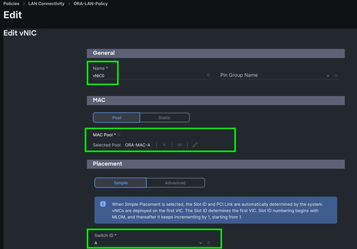
Step 3. In the Policy Details section, click Add vNIC. In the Add vNIC section, for the first vNIC enter vNIC0. In the Edit vNIC section, for the vNIC name enter "vNIC0" and for the MAC Pool select ORA-MAC-A.
Step 4. In the Placement option, select Simple and for the Switch ID select A as shown below:
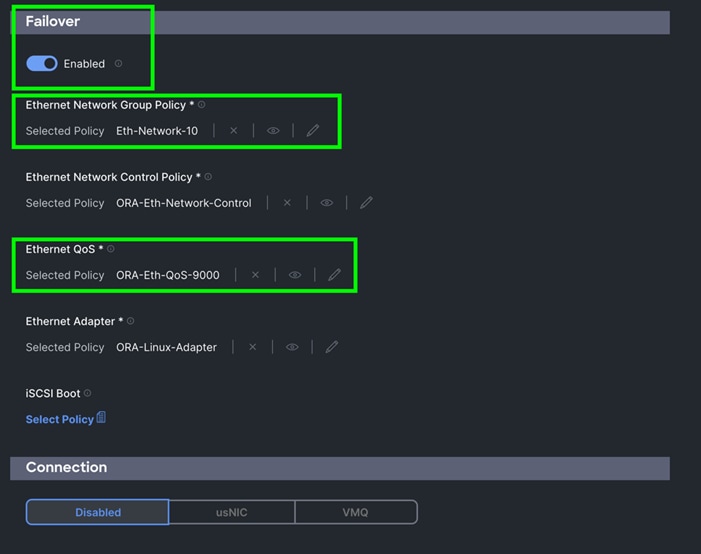
Step 5. For Failover select Enable for this vNIC configuration. This enables the vNIC to failover to another FI.
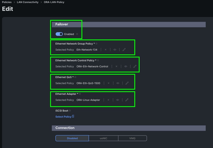
Step 6. For the Ethernet Network Group Policy, select Eth-Network-134. For the Ethernet Network Control Policy select ORA-Eth-Network-Control. For Ethernet QoS, select ORA-Eth-QoS-1500, and for the Ethernet Adapter, select ORA-Linux-Adapter. Click Add to add vNIC0 to this policy.
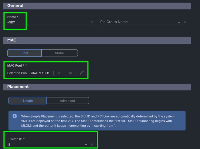
Step 7. Add a second vNIC. For the name enter "vNIC1" and for the MAC Pool select ORA-MAC-B.
Step 8. In the Placement option, select Simple and for the Switch ID select B as shown below:
Step 9. For Failover select Enable for this vNIC configuration. This enables the vNIC to failover to another FI.
Step 10. For the Ethernet Network Group Policy, select Eth-Network-10. For the Ethernet Network Control Policy, select ORA-Eth-Network-Control. For the Ethernet QoS, select ORA-Eth-QoS-9000, and for the Ethernet Adapter, select ORA-Linux-Adapter. Click Add to add vNIC0 to this policy.
Step 11. Click Add to add vNIC1 into this policy.
Step 12. After adding these two vNICs, review and make sure the Switch ID, PCI Order, Failover Enabled, and MAC Pool are as shown below:
Step 13. Click Create to create this policy.
Procedure 10. Create Fibre Channel Network Policy
Step 1. To configure the Fibre Channel Network Policy for the UCS Server profile, go to > Infrastructure Service > Configure > Polices > and click Create Policy.
Step 2. For the platform type select UCS Server and for the policy select Fibre Channel Network.
Note: For this solution, we configured two Fibre Channel network policy as “ORA-FC-Network-151” and “ORA-FC-Network-152” to carry two VSAN traffic 151 and 152 on each of the Fabric Interconnect.
Step 3. In the Create Fibre Channel Network Configuration section, for the Organization select ORA21 and for the policy name enter “ORA-FC-Network-151.” Click Next.
Step 4. For the VSAN ID enter 151 as shown below:

Step 5. Click Create to create this policy for VSAN 151.
Step 6. Create another Fibre Channel Network Policy for the UCS Server profile, go to > Infrastructure Service > Configure > Polices > and click Create Policy.
Step 7. For the platform type select UCS Server and for the policy select Fibre Channel Network.
Step 8. In the Create Fibre Channel Network Configuration section, for the Organization select ORA21 and for the policy name enter “ORA-FC-Network-152.” Click Next.
Step 9. For the VSAN ID enter 152 as shown below:

Step 10. Click Create to create this policy for VSAN 152.
Procedure 11. Create Fibre Chanel QoS Policy
Step 1. To configure the Fibre Channel QoS Policy for the UCS Server profile, go to > Infrastructure Service > Configure > Polices > and click Create Policy.
Step 2. For the platform type select UCS Server and for the policy select Fibre Channel QoS.
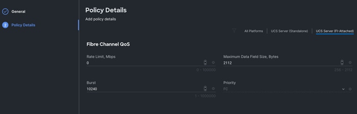
Step 3. In the Create Fibre Channel QoS Configuration section, for the Organization select ORA21 and for the policy name enter ORA-FC-QoS click Next.
Step 4. Enter QoS Settings as shown below to configure QoS for Fibre Channel for vHBA0:
Step 5. Click Create to create this policy for Fibre Channel QoS.
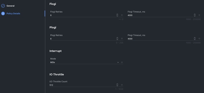
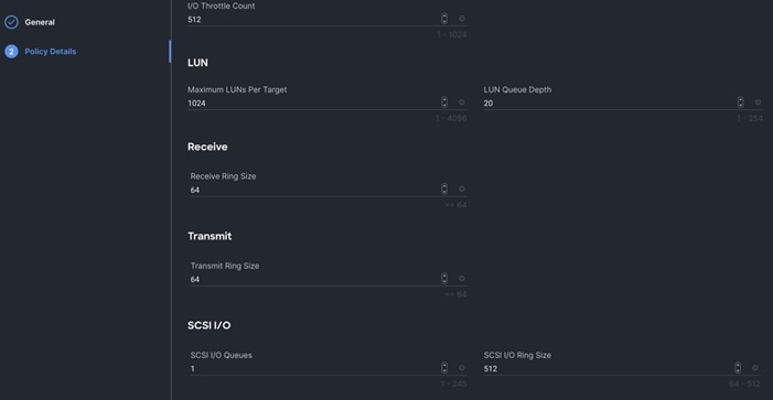
Procedure 12. Create Fibre Channel Adapter Policy
Step 1. To configure the Fibre Channel Adapter Policy for the UCS Server profile, go to > Infrastructure Service > Configure > Polices > and click Create Policy.
Step 2. For the platform type select UCS Server” and for the policy select Fibre Channel Adapter.
Step 3. In the Create Fibre Channel Adapter Configuration section, for the Organization select ORA21 and for the policy name enter “ORA-FC-Adapter-Linux”. For the Fibre Channel Adapter Default Configuration, select Linux and click Next.
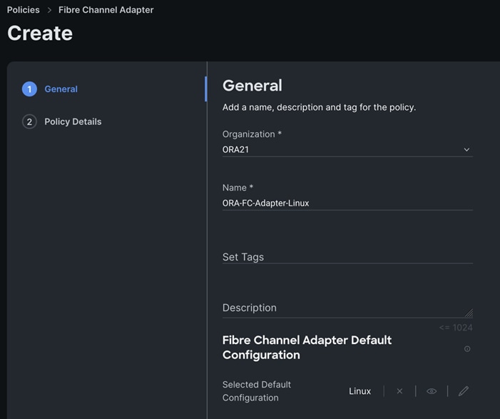
Note: For this solution, we used the default linux adapter settings to configure the FC and NVMe FC HBA’s.
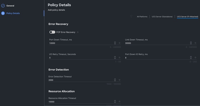
Step 4. Click Create to create this policy for vHBA.
Procedure 13. Configure SAN Connectivity Policy
As mentioned previously, two vHBA (HBA0 and HBA1) were configured for Boot from SAN on two VSANs. HBA0 was configured to carry the FC Network Traffic on VSAN 151 and boot from SAN through the MDS-A Switch while HBA1 was configured to carry the FC Network Traffic on VSAN 152 and boot from SAN through the MDS-B Switch.
Note: For the best performance, we recommend creating at least 8 vHBAs to run NVMe/FC traffic. Also, for this solution, we configured 8 vHBAs to run workload for NVMe/FC traffic.
A total of eight vHBAs were configured to carry the NVMe/FC network traffic for the database on two VSANs. Four vHBAs (HBA2, HBA4, HBA6 and HBA8) were configured to carry the NVMe/FC network traffic on VSAN 151 for Oracle RAC database storage traffic through MDS-A Switch. Four vHBA (HBA3, HBA5, HBA7 and HBA9) were configured to carry the NVMe/FC network traffic on VSAN 152 for Oracle RAC database storage traffic through the MDS-B Switch.
For each Server node, a total of 10 vHBAs were configured as listed in Table 10.
| Name |
vHBA Type |
Switch ID |
PCI-Order |
Fibre Channel Network |
Fibre Channel Adapter |
Fibre Channel QoS |
| HBA0 |
fc-initiator |
FI – A |
2 |
ORA-FC-Network-151 |
ORA-FC-Adapter-Linux |
ORA-FC-QoS |
| HBA1 |
fc-initiator |
FI – B |
3 |
ORA-FC-Network-152 |
ORA-FC-Adapter-Linux |
ORA-FC-QoS |
| HBA2 |
fc-nvme-initiator |
FI – A |
4 |
ORA-FC-Network-151 |
ORA-FC-Adapter-Linux |
ORA-FC-QoS |
| HBA3 |
fc-nvme-initiator |
FI – B |
5 |
ORA-FC-Network-152 |
ORA-FC-Adapter-Linux |
ORA-FC-QoS |
| HBA4 |
fc-nvme-initiator |
FI – A |
6 |
ORA-FC-Network-151 |
ORA-FC-Adapter-Linux |
ORA-FC-QoS |
| HBA5 |
fc-nvme-initiator |
FI – B |
7 |
ORA-FC-Network-152 |
ORA-FC-Adapter-Linux |
ORA-FC-QoS |
| HBA6 |
fc-nvme-initiator |
FI – A |
8 |
ORA-FC-Network-151 |
ORA-FC-Adapter-Linux |
ORA-FC-QoS |
| HBA7 |
fc-nvme-initiator |
FI – B |
9 |
ORA-FC-Network-152 |
ORA-FC-Adapter-Linux |
ORA-FC-QoS |
| HBA8 |
fc-nvme-initiator |
FI – A |
10 |
ORA-FC-Network-151 |
ORA-FC-Adapter-Linux |
ORA-FC-QoS |
| HBA9 |
fc-nvme-initiator |
FI – B |
11 |
ORA-FC-Network-152 |
ORA-FC-Adapter-Linux |
ORA-FC-QoS |
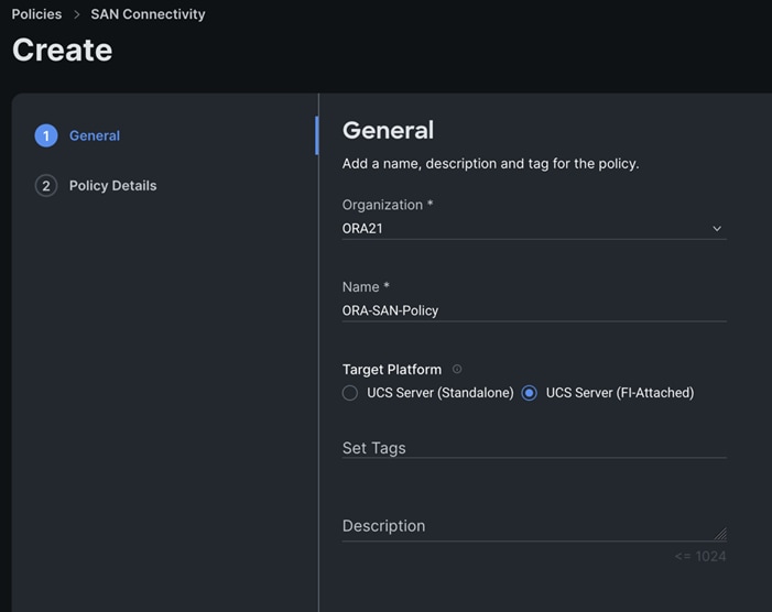
Step 1. Go to > Infrastructure Service > Configure > Polices > and click Create Policy. For the platform type select UCS Server and for the policy select SAN Connectivity.
Step 2. In the SAN Connectivity Policy Create section, for the Organization select ORA21,for the policy name enter ORA-SAN-Policy and for the Target Platform select UCS Server (FI-Attached). Click Next.
Step 3. In the Policy Details section, select WWNN Pool and then select WWNN-Pool that you previously created. Click Add vHBA.
Step 4. In the Add vHBA section, for the Name enter “HBA0” and for the vHBA Type enter “fc-initiator.”
Step 5. For the WWPN Pool, select the WWPN-Pool that you previously created, as shown below:
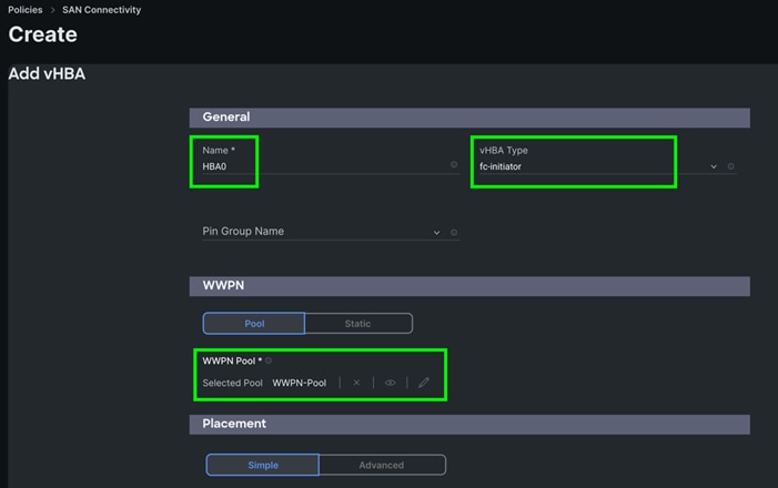
Step 6. For the Placement, keep the option Simple and for the Switch ID select A and for the PCI Order select 2.
Step 7. For the Fibre Channel Network select ORA-FC-Network-151.
Step 8. For the Fibre Channel QoS select ORA-FC-QoS.
Step 9. For the Fibre Channel Adapter select ORA-FC-Adapter-Linux.
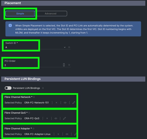
Step 10. Click Add to add this first HBA0.
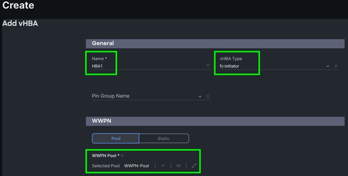
Step 11. Click Add vHBA to add a second HBA.
Step 12. In the Add vHBA section, for the Name enter “HBA1” and for the vHBA Type select fc-initiator.
Step 13. For the WWPN Pool select WWPN-Pool that was previously create, as shown below:
Step 14. For the Placement, keep the option Simple and for Switch ID select B and for the PCI Order select 3.
Step 15. For the Fibre Channel Network select ORA-FC-Network-152.
Step 16. For the Fibre Channel QoS select ORA-FC-QoS.
Step 17. For the Fibre Channel Adapter select ORA-FC-Adapter-Linux.
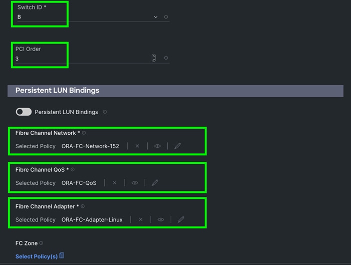
Step 18. Click Add to add this second HBA1.
Note: For this solution, we added another eight HBA for NVME/FC.
Step 19. Click Add vHBA.
Step 20. In the Add vHBA section, for the Name enter “HBA2” and for the vHBA Type select fc-nvme-initiator.
Step 21. For the WWPN Pool select WWPN-Pool, which was previously created, as shown below:
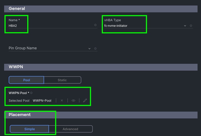
Step 22. For the Placement, keep the option Simple and for the Switch ID select A and for the PCI Order select 4.
Step 23. For the Fibre Channel Network select ORA-FC-Network-151.
Step 24. For the Fibre Channel QoS select ORA-FC-QoS.
Step 25. For the Fibre Channel Adapter select ORA-FC-Adapter-Linux.
Step 26. Click Add to add this HBA2.
Note: For this solution, we added another seven HBA for NVME/FC.
Step 27. Click Add vHBA and select the appropriate vHBA Type, WWPN Pool, Simple Placement, Switch ID, PCI Order, Fibre Channel Network, Fibre Channel QoS, and Fibre Channel Adapter for all rest of the HBAs listed in Table 10.
Step 28. After adding the ten vHBAs, review and make sure the Switch ID, PCI Order, and HBA Type are as shown below:
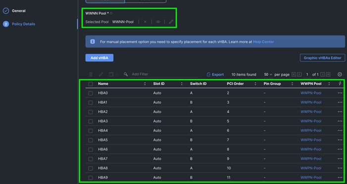
Step 29. Click Create to create this policy.
Procedure 14. Configure Boot Order Policy
All Oracle server nodes are set to boot from SAN for this Cisco Validated Design, as part of the Service Profile. The benefits of booting from SAN are numerous; disaster recovery, lower cooling, and power requirements for each server since a local drive is not required, and better performance, and so on. We strongly recommend using “Boot from SAN” to realize the full benefits of Cisco UCS stateless computing features, such as service profile mobility.
Note: For this solution, we used SAN Boot and configured the SAN Boot order policy as detailed in this procedure.
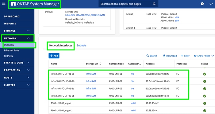
To create SAN Boot Order Policy, you need to enter the WWPN of NetApp Storage. The screenshot below shows both the NetApp AFF A900 Controller FC Ports and related WWPN:
Step 1. To configure Boot Order Policy for UCS Server profile, go to > Infrastructure Service > Configure > Polices > and click Create Policy.
Step 2. For the platform type select UCS Server and for the policy select Boot Order.
Step 3. In the Boot Order Policy Create section, for the Organization select ORA21 and for the name of the Policy select SAN-Boot. Click Next.
Step 4. In the Policy Details section, click Add Boot Device and select Virtual Media for the first boot order. Name the device “KVM-DVD” and for the Sub-type select KVM MAPPED DVD as shown below:
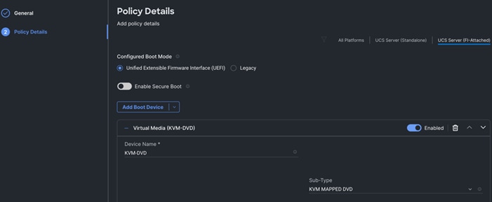
Step 5. Add the second boot order: Click Add Boot Device and for the second boot order for HBA0, select SAN Boot as the primary path through the NetApp Controller CT1 LIF.
Step 6. Enter the Device Name, Interface Name, and Target WWPN according to storage target.
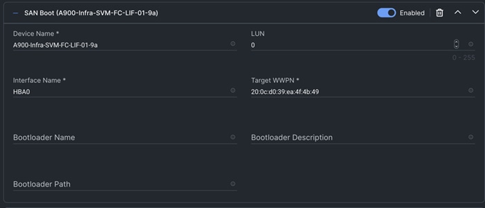
Note: We added a third boot order and the appropriate target for HBA1 as the primary path through NetApp Controller CT1 LIF as shown in the screenshot below.
Step 7. Enter the Device Name, Interface Name, and Target WWPN according to storage target.
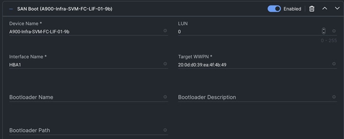
Note: We added a fourth boot order for HBA0 as the secondary path through NetApp Controller CT2 LIF.
Step 8. Enter the Device Name, Interface Name and Target WWPN according to storage target.
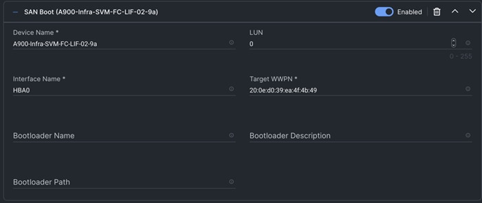
Note: We added a fifth boot order for HBA1 as the secondary path through NetApp Controller CT2 LIF.
Step 9. Enter the Device Name, Interface Name and Target WWPN according to storage target.
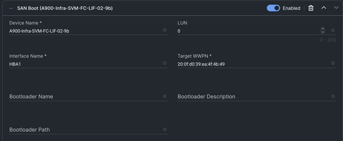
Step 10. By configuring both FC Boot HBAs (HBA0 and HBA1) with the Primary and Secondary path, you have configured high availability for SAN boot, as well as a fourth path for the OS Boot LUNs.
Step 11. Review the Policy details and verify that all four SAN boot paths are configured to provide high availability as shown below:
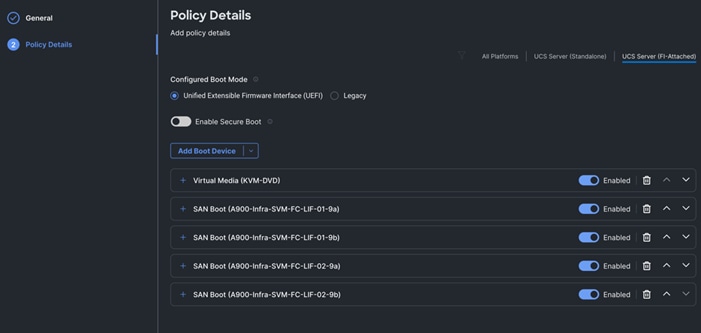
Step 12. Click Create to create this SAN boot order policy.
Procedure 15. Configure and Deploy Server Profiles
The Cisco Intersight server profile allows server configurations to be deployed directly on the compute nodes based on polices defined in the profile. After a server profile has been successfully created, server profiles can be attached with the Cisco UCS X410c M7 Compute Nodes.
Note: For this solution, we configured four server profiles; FLEX1 to FLEX4. We assigned the server profile FLEX1 to Chassis 1 Server 1, server profile FLEX2 to Chassis 1 Server 5, server profile FLEX3 to Chassis 2 Server 1 and server profile FLEX4 to Chassis 2 Server 5.
Note: All four x410c M7 servers will be used to create Oracle RAC database nodes later in the database creation section.
Note: For this solution, we configured one server profile “Flex1” and attached all policies for the server profile which were configured in the previous section. We cloned the first server profile and created three more server profiles; “Flex2”, “Flex3” and “Flex4”. Alternatively, you can create a server profile template with all server profile policies and the derive server profile from the standard template.
Step 1. To create a server profile, go to > Infrastructure Service > Configure > Profile > and then select the tab for UCS Server Profile. Click Create UCS Server Profile.
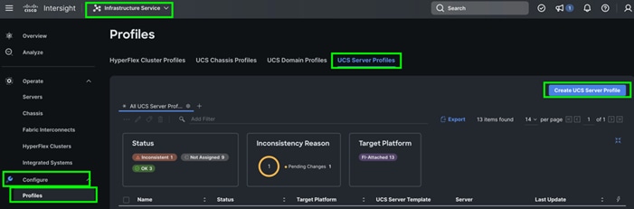
Step 2. In Create Server Profile, for the Organization select ORA21 and for the Name for the Server Profile enter “Flex1.” For the Target Platform type select UCS Server (FI-Attached).
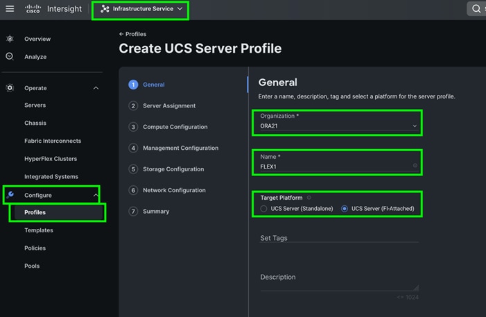
Step 3. In the Server Assignment menu, select Chassis 1 Server 1 to assign this server profile and click Next.
Step 4. In the Compute Configuration menu, select UUID Pool and select the ORA-UUID option that you previously created. For the BIOS select ORA-BIOS and for the Boot Order select SAN-Boot that you previously created. Click Next.
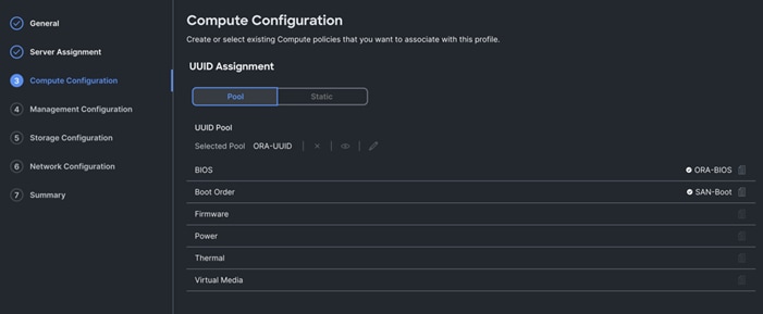
Step 5. In the Management Configuration menu, for the IMC Access select ORA-IMC-Access to configure the Server KVM access and then click Next.
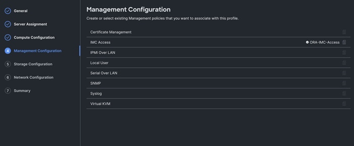
Note: We didn’t configure any local storage or any storage policies for this solution.
Step 6. Click Next to go to Network configuration.
Step 7. For the Network Configuration section, for the LAN connectivity select ORA-LAN-Policy and for the SAN connectivity select ORA-SAN-Policy that you previously created.
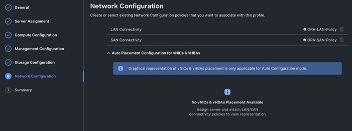
Note: By assigning these LAN and SAN connectivity in the server profile, the server profile will create and configure two vNIC and ten vHBA on the server for management, private interconnect, and storage network traffic.
Step 8. Click Next and review the summary for the server profile and click Deploy to assign this server profile to the first server.
Note: After this server profile “FLEX1” deploys successfully on chassis 1 server 1, you can clone this server profile to create another three identical server profile for the rest of the three remaining server nodes.
Step 9. To clone and create another server profile, go to Infrastructure Service > Configure > Profiles > UCS Server Profiles and Select server Profile FLEX1 and click the radio button “---” and select option Clone as shown below:
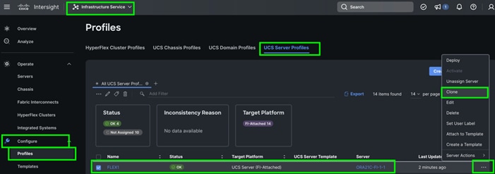
Step 10. From the Clone configuration menu, select Chassis 1 Server 5 and click Next. For the Server Profile Clone Name enter “FLEX2” and for the Organization select ORA21 to create a second server profile for the second Cisco UCS x410c M7 server on chassis 1 server 5.
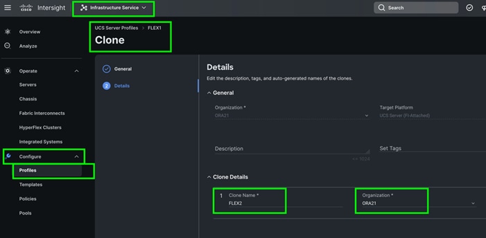
Note: We created two more server profile clones; FLEX3 and FLEX4 and assigned these cloned server profiles to Chassis 2 Server 1 and Chassis 2 Server 5.
The following screenshot shows the server profiles with the Cisco UCS domain and assigned servers from both chassis:
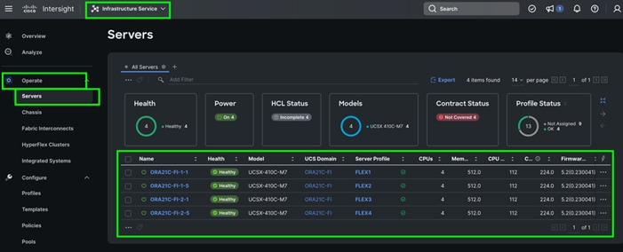
After the successful deployment of the server profile, the Cisco UCS X410c M7 Compute Nodes are configured with the parameters defined in the server profile. This completed Cisco UCS X-Series and Intersight Managed Mode (IMM) configuration can boot each server node from SAN LUN.
Cisco MDS Switch Configuration
This section provides a detailed procedure for configuring the Cisco MDS 9132T Switches.
IMPORTANT! Follow these steps precisely because failure to do so could result in an improper configuration.
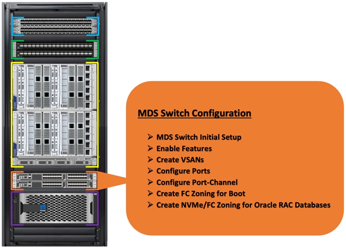
The Cisco MDS Switches are connected to the Fabric Interconnects and the NetApp AFF A900 Storage System as shown below:
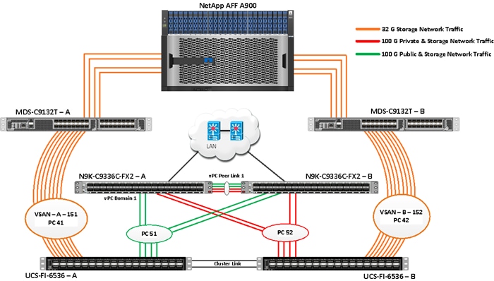
For this solution, eight ports (ports 1 to 8) of the MDS Switch A were connected to the Fabric Interconnect A (ports 1/35/1-4 and 1/36/1-4). The port-channel (PC 41) was configured on these ports between MDS-A to FI-A. Eight ports (ports 1 to 8) of the MDS Switch B were connected to the Fabric Interconnect B (ports 1/35/1-4 and ports 1/36/1-4). Another port-channel (PC 42) was created and on these ports were MDS-B to FI-B. All of the ports carry 32 Gb/s FC Traffic. Table 11 lists the port connectivity of Cisco MDS Switches to the Fabric Interconnects.
Table 11. Cisco MDS Switch Port connectivity to Fabric Interconnects
| vPC Description |
vPC ID |
Fabric Interconnects Ports |
Cisco MDS Switch Ports |
Allowed VSANs |
| Port Channel between MDS-A and FI-A |
41 |
FI-A Port 1/35/1 |
MDS-A-1/1 |
151 |
| FI-A Port 1/35/2 |
MDS-A-1/2 |
|||
| FI-A Port 1/35/3 |
MDS-A-1/3 |
|||
| FI-A Port 1/35/4 |
MDS-A-1/4 |
|||
| FI-A Port 1/36/1 |
MDS-A-1/5 |
|||
| FI-A Port 1/36/2 |
MDS-A-1/6 |
|||
| FI-A Port 1/36/3 |
MDS-A-1/7 |
|||
| FI-A Port 1/36/4 |
MDS-A-1/8 |
|||
| Port Channel between MDS-B and FI-B |
42 |
FI-B Port 1/35/1 |
MDS-B-1/1 |
152 |
| FI-B Port 1/35/2 |
MDS-B-1/2 |
|||
| FI-B Port 1/35/3 |
MDS-B-1/3 |
|||
| FI-B Port 1/35/4 |
MDS-B-1/4 |
|||
| FI-B Port 1/36/1 |
MDS-B-1/5 |
|||
| FI-B Port 1/36/2 |
MDS-B-1/6 |
|||
| FI-B Port 1/36/3 |
MDS-B-1/7 |
|||
| FI-B Port 1/36/4 |
MDS-B-1/8 |
For this solution, four ports (ports 17 to 20) of the MDS Switch A were connected to the NetApp AFF A900 Storage controller. Four ports (ports 17 to 20) of the MDS Switch B were connected to the NetApp AFF A900 Storage controller. All ports carry 32 Gb/s FC Traffic. Table 12 lists the port connectivity of Cisco MDS Switches to NetApp AFF A900 Controller.
Table 12. Cico MDS Switches port connectivity to the NetApp AFF A900 Controller
| MDS Switch |
MDS Switch Port |
NetApp Storage Controller |
NetApp Controller Ports |
Descriptions |
| MDS Switch A |
FC Port 1/17 |
NetApp A900 Controller-1 |
A900-01-9a |
A900-LNR-CT1-9A |
| FC Port 1/18 |
NetApp A900 Controller-2 |
A900-02-9a |
A900-LNR-CT2-9A |
|
| FC Port 1/19 |
NetApp A900 Controller-1 |
A900-01-9c |
A900-LNR-CT1-9C |
|
| FC Port 1/20 |
NetApp A900 Controller-2 |
A900-02-9c |
A900-LNR-CT2-9C |
|
| MDS Switch B |
FC Port 1/17 |
NetApp A900 Controller-1 |
A900-01-9b |
A900-LNR-CT1-9B |
| FC Port 1/18 |
NetApp A900 Controller-2 |
A900-02-9b |
A900-LNR-CT2-9B |
|
| FC Port 1/19 |
NetApp A900 Controller-1 |
A900-01-9d |
A900-LNR-CT1-9D |
|
| FC Port 1/20 |
NetApp A900 Controller-2 |
A900-02-9d |
A900-LNR-CT2-9D |
The following procedures describe how to configure the Cisco MDS switches for use in a base FlexPod environment. These procedures assume you’re using Cisco MDS 9332T FC switches.
Cisco Feature on Cisco MDS Switches
Procedure 1. Configure Features
Step 1. Login as admin user into MDS Switch A and MDS Switch B and run the following commands:
config terminal
feature npiv
feature fport-channel-trunk
copy running-config startup-config
Procedure 2. Configure VSANs and Ports
Step 1. Login as Admin User into MDS Switch A.
Step 2. Create VSAN 151 for Storage network traffic and configure the ports by running the following commands:
config terminal
vsan database
vsan 151
vsan 151 name "VSAN-FI-A"
vsan 151 interface fc 1/1-24
interface port-channel 41
switchport trunk allowed vsan 151
switchport description Port-Channel-FI-A-MDS-A
switchport rate-mode dedicated
switchport trunk mode off
no shut
interface fc1/1
switchport description ORA21C-FI-A-1/35/1
switchport trunk mode off
port-license acquire
channel-group 41 force
no shutdown
interface fc1/2
switchport description ORA21C-FI-A-1/35/2
switchport trunk mode off
port-license acquire
channel-group 41 force
no shutdown
interface fc1/3
switchport description ORA21C-FI-A-1/35/3
switchport trunk mode off
port-license acquire
channel-group 41 force
no shutdown
interface fc1/4
switchport description ORA21C-FI-A-1/35/4
switchport trunk mode off
port-license acquire
channel-group 41 force
no shutdown
interface fc1/5
switchport description ORA21C-FI-A-1/36/1
switchport trunk mode off
port-license acquire
channel-group 41 force
no shutdown
interface fc1/6
switchport description ORA21C-FI-A-1/36/2
switchport trunk mode off
port-license acquire
channel-group 41 force
no shutdown
interface fc1/7
switchport description ORA21C-FI-A-1/36/3
switchport trunk mode off
port-license acquire
channel-group 41 force
no shutdown
interface fc1/8
switchport description ORA21C-FI-A-1/36/4
switchport trunk mode off
port-license acquire
channel-group 41 force
no shutdown
interface fc1/17
switchport trunk allowed vsan 151
switchport description A900-01-NVMe-FC-LIF-9a
switchport trunk mode off
port-license acquire
no shutdown
interface fc1/18
switchport trunk allowed vsan 151
switchport description A900-02-NVMe-FC-LIF-9a
switchport trunk mode off
port-license acquire
no shutdown
interface fc1/19
switchport trunk allowed vsan 151
switchport description A900-01-NVMe-FC-LIF-9c
switchport trunk mode off
port-license acquire
no shutdown
interface fc1/20
switchport trunk allowed vsan 151
switchport description A900-02-NVMe-FC-LIF-9c
switchport trunk mode off
port-license acquire
no shutdown
vsan database
vsan 151 interface port-channel 41
vsan 151 interface fc1/17
vsan 151 interface fc1/18
vsan 151 interface fc1/19
vsan 151 interface fc1/20
copy running-config startup-config
Step 3. Login as Admin User into MDS Switch B
Step 4. Create VSAN 152 for Storage network traffic and configure the ports by running the following commands:
config terminal
vsan database
vsan 152
vsan 152 name "VSAN-FI-B"
vsan 152 interface fc 1/1-24
interface port-channel 42
switchport trunk allowed vsan 152
switchport description Port-Channel-FI-B-MDS-B
switchport rate-mode dedicated
switchport trunk mode off
no shut
interface fc1/1
switchport description ORA21C-FI-B-1/35/1
switchport trunk mode off
port-license acquire
channel-group 42 force
no shutdown
interface fc1/2
switchport description ORA21C-FI-B-1/35/2
switchport trunk mode off
port-license acquire
channel-group 42 force
no shutdown
interface fc1/3
switchport description ORA21C-FI-B-1/35/3
switchport trunk mode off
port-license acquire
channel-group 42 force
no shutdown
interface fc1/4
switchport description ORA21C-FI-B-1/35/4
switchport trunk mode off
port-license acquire
channel-group 42 force
no shutdown
interface fc1/5
switchport description ORA21C-FI-B-1/36/1
switchport trunk mode off
port-license acquire
channel-group 42 force
no shutdown
interface fc1/6
switchport description ORA21C-FI-B-1/36/2
switchport trunk mode off
port-license acquire
channel-group 42 force
no shutdown
interface fc1/7
switchport description ORA21C-FI-B-1/36/3
switchport trunk mode off
port-license acquire
channel-group 42 force
no shutdown
interface fc1/8
switchport description ORA21C-FI-B-1/36/4
switchport trunk mode off
port-license acquire
channel-group 42 force
no shutdown
interface fc1/17
switchport trunk allowed vsan 152
switchport description A900-01-NVMe-FC-LIF-9b
switchport trunk mode off
port-license acquire
no shutdown
interface fc1/18
switchport trunk allowed vsan 152
switchport description A900-02-NVMe-FC-LIF-9b
switchport trunk mode off
port-license acquire
no shutdown
interface fc1/19
switchport trunk allowed vsan 152
switchport description A900-01-NVMe-FC-LIF-9d
switchport trunk mode off
port-license acquire
no shutdown
interface fc1/20
switchport trunk allowed vsan 152
switchport description A900-02-NVMe-FC-LIF-9d
switchport trunk mode off
port-license acquire
no shutdown
vsan database
vsan 152 interface port-channel 42
vsan 152 interface fc1/17
vsan 152 interface fc1/18
vsan 152 interface fc1/19
vsan 152 interface fc1/20
copy running-config startup-config
Procedure 3. Create and configure Fibre Channel Zoning for FC Boot
This procedure sets up the Fibre Channel connections between the Cisco MDS 9132T switches, the Cisco UCS Fabric Interconnects, and the NetApp AFF Storage systems. Before you configure the zoning details, decide how many paths are needed for each LUN and extract the WWPN numbers for each of the HBAs from each server.
For this solution, 10 vHBAs were configured on each server node. Two vHBA (HBA0 and HBA1) were created to carry the FC Network Traffic and Boot from SAN through MDS-A and MDS-B Switches. Another eight vHBAs (HBA2 to HBA9) were configured for the NVMe/FC Network Traffic (Oracle RAC Storage Traffic) through MDS-A and MDS-B Switch.
Step 1. Log in to Cisco Intersight and go to Infrastructure service > Operate > Servers > and click server 1 (server profile as FLEX1).
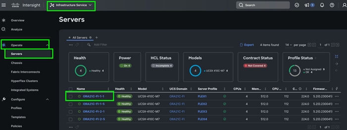
Step 2. Go to the UCS Server Profile tab and select connectivity to get the details of all of the HBAs and their respective WWPN ID as shown below:
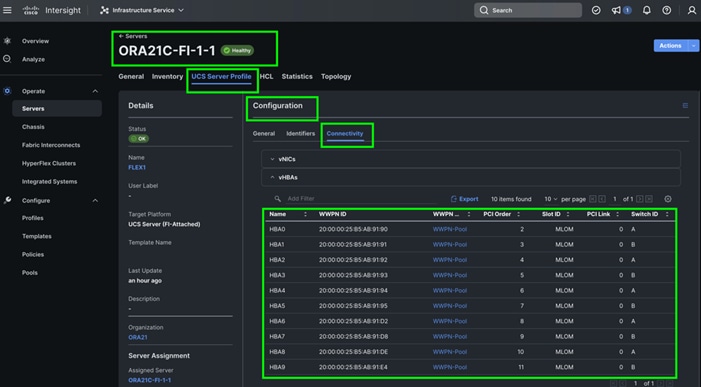
Step 3. Log into Cisco Intersight and go to Infrastructure service > Operate > Servers > and click server 1 (server profile as FLEX1).
Step 4. Go to UCS Manager > Equipment > Chassis > Servers and select the desired server. From the menu, click the Inventory tab and the HBA sub-tab to get the WWPN of the HBA’s.
Note: For this solution, HBA0 (through FI-A) and HBA1 (Through FI-B) were configured for FC SAN Boot and one dedicated FC boot zone was created across both MDS switches.
Note: Four HBAs (HBA2, HBA4, HBA6 and HBA8 through FI-A) and four HBAs (HBA3, HBA5, HBA7 and HBA9 through FI-B) were configured for the NVMe FC database traffic and a dedicated NVMe FC zone was created across both MDS switches.
Step 5. Login into the NetApp storage controller and extract the WWPN of FC LIFs and verify that the port information is correct. This information can be found in the NetApp Storage GUI under Network > Network Interfaces.
Note: For this solution, we configured three SVMs.
Note: One SVM named “Infra-SVM” was configured to carry FC network traffic for SAN Boot while the other two SVMs named “ORA21C-SVM” and “ORA21C-SVM2” were configured to run NVMe/FC Network Traffic for Oracle RAC Databases. The screenshot below shows the allowed protocols configured for all three SVMs:
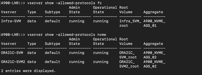
The WWPN and ports connectivity configured for NetApp AFF A900 Storage Controller are shown below:
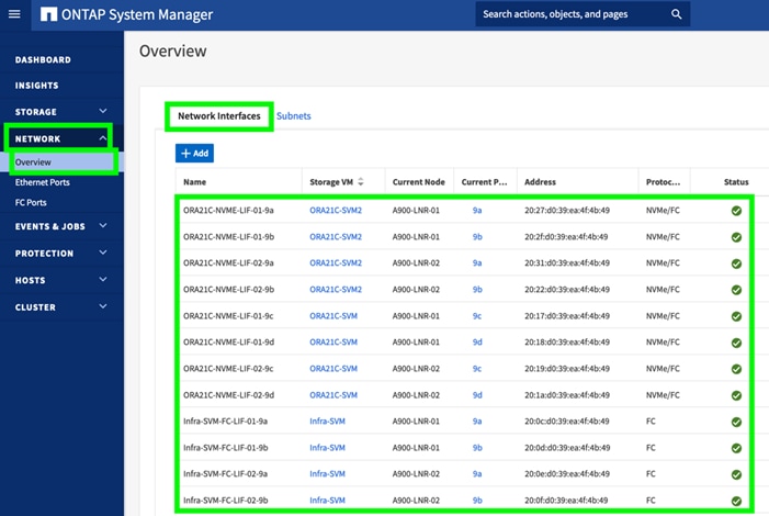
Note: For SVM “Infra-SVM”, two FC Logical Interfaces (LIFs) were created on storage controller cluster node 1 (Infra-SVM-FC-LIF-01-9a and Infra-SVM-FC-LIF-01-9b) and two Fibre Channel LIFs were created on storage controller cluster node 2 (Infra-SVM-FC-LIF-02-9a and Infra-SVM-FC-LIF-01-9b).
Note: For SVM “ORA21C-SVM”, two NVMe Logical Interfaces (LIFs) were created on storage controller cluster node 1 (ORA21C-NVME-LIF-01-9c and ORA21C-NVME-LIF-01-9d) and two NVMe LIFs are created on storage controller cluster node 2 (ORA21C-NVME-LIF-02-9c and ORA21C-NVME-LIF-02-9d).
Note: To take advantage of all eight FC ports on running NVMe/FC traffic, another NVMe SVM was created and named “ORA21C-SVM2”. In the second NVMe/FC SVM, two NVMe Logical Interfaces (LIFs) were created on storage controller cluster node 1 (ORA21C-NVME-LIF-01-9a and ORA21C-NVME-LIF-01-9b) and two NVMe LIFs were created on storage controller cluster node 2 (ORA21C-NVME-LIF-02-9a and ORA21C-NVME-LIF-02-9b).
Step 6. To obtain the port information, log into the storage cluster and run the network interface show command as shown below:
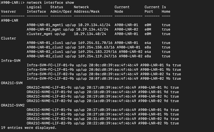
For this solution, device aliases were created for zoning on MDS Switch A and Switch B as detailed below:
Step 7. To configure device aliases and zones for FC and NVMe/FC Network data paths on MDS switch A, complete the following steps
Step 8. Login as admin user and run the following commands into MDS Switch A:
config terminal
device-alias database
device-alias name FLEX1-FC-HBA0 pwwn 20:00:00:25:b5:ab:91:90
device-alias name FLEX2-FC-HBA0 pwwn 20:00:00:25:b5:ab:91:96
device-alias name FLEX3-FC-HBA0 pwwn 20:00:00:25:b5:ab:91:c0
device-alias name FLEX4-FC-HBA0 pwwn 20:00:00:25:b5:ab:91:a2
device-alias name FLEX1-NVMe-HBA2 pwwn 20:00:00:25:b5:ab:91:92
device-alias name FLEX1-NVMe-HBA4 pwwn 20:00:00:25:b5:ab:91:94
device-alias name FLEX1-NVMe-HBA6 pwwn 20:00:00:25:b5:ab:91:d2
device-alias name FLEX1-NVMe-HBA8 pwwn 20:00:00:25:b5:ab:91:de
device-alias name FLEX2-NVMe-HBA2 pwwn 20:00:00:25:b5:ab:91:98
device-alias name FLEX2-NVMe-HBA4 pwwn 20:00:00:25:b5:ab:91:9a
device-alias name FLEX2-NVMe-HBA6 pwwn 20:00:00:25:b5:ab:91:d3
device-alias name FLEX2-NVMe-HBA8 pwwn 20:00:00:25:b5:ab:91:df
device-alias name FLEX3-NVMe-HBA2 pwwn 20:00:00:25:b5:ab:91:c2
device-alias name FLEX3-NVMe-HBA4 pwwn 20:00:00:25:b5:ab:91:c4
device-alias name FLEX3-NVMe-HBA6 pwwn 20:00:00:25:b5:ab:91:d7
device-alias name FLEX3-NVMe-HBA8 pwwn 20:00:00:25:b5:ab:91:e3
device-alias name FLEX4-NVMe-HBA2 pwwn 20:00:00:25:b5:ab:91:a4
device-alias name FLEX4-NVMe-HBA4 pwwn 20:00:00:25:b5:ab:91:a6
device-alias name FLEX4-NVMe-HBA6 pwwn 20:00:00:25:b5:ab:91:d4
device-alias name FLEX4-NVMe-HBA8 pwwn 20:00:00:25:b5:ab:91:e0
device-alias name Infra-SVM-FC-LIF-01-9a pwwn 20:0c:d0:39:ea:4f:4b:49
device-alias name Infra-SVM-FC-LIF-02-9a pwwn 20:0e:d0:39:ea:4f:4b:49
device-alias name ORA21C-NVME-LIF-01-9a pwwn 20:27:d0:39:ea:4f:4b:49
device-alias name ORA21C-NVME-LIF-01-9c pwwn 20:17:d0:39:ea:4f:4b:49
device-alias name ORA21C-NVME-LIF-02-9a pwwn 20:31:d0:39:ea:4f:4b:49
device-alias name ORA21C-NVME-LIF-02-9c pwwn 20:19:d0:39:ea:4f:4b:49
device-alias commit
copy run start
Step 9. Login as admin user and run the following commands into MDS Switch B:
config terminal
device-alias database
device-alias name FLEX1-FC-HBA1 pwwn 20:00:00:25:b5:ab:91:91
device-alias name FLEX2-FC-HBA1 pwwn 20:00:00:25:b5:ab:91:97
device-alias name FLEX3-FC-HBA1 pwwn 20:00:00:25:b5:ab:91:c1
device-alias name FLEX4-FC-HBA1 pwwn 20:00:00:25:b5:ab:91:a3
device-alias name FLEX1-NVMe-HBA3 pwwn 20:00:00:25:b5:ab:91:93
device-alias name FLEX1-NVMe-HBA5 pwwn 20:00:00:25:b5:ab:91:95
device-alias name FLEX1-NVMe-HBA7 pwwn 20:00:00:25:b5:ab:91:d8
device-alias name FLEX1-NVMe-HBA9 pwwn 20:00:00:25:b5:ab:91:e4
device-alias name FLEX2-NVMe-HBA3 pwwn 20:00:00:25:b5:ab:91:99
device-alias name FLEX2-NVMe-HBA5 pwwn 20:00:00:25:b5:ab:91:9b
device-alias name FLEX2-NVMe-HBA7 pwwn 20:00:00:25:b5:ab:91:d9
device-alias name FLEX2-NVMe-HBA9 pwwn 20:00:00:25:b5:ab:91:e5
device-alias name FLEX3-NVMe-HBA3 pwwn 20:00:00:25:b5:ab:91:c3
device-alias name FLEX3-NVMe-HBA5 pwwn 20:00:00:25:b5:ab:91:c5
device-alias name FLEX3-NVMe-HBA7 pwwn 20:00:00:25:b5:ab:91:dd
device-alias name FLEX3-NVMe-HBA9 pwwn 20:00:00:25:b5:ab:91:e9
device-alias name FLEX4-NVMe-HBA3 pwwn 20:00:00:25:b5:ab:91:a5
device-alias name FLEX4-NVMe-HBA5 pwwn 20:00:00:25:b5:ab:91:a7
device-alias name FLEX4-NVMe-HBA7 pwwn 20:00:00:25:b5:ab:91:da
device-alias name FLEX4-NVMe-HBA9 pwwn 20:00:00:25:b5:ab:91:e6
device-alias name Infra-SVM-FC-LIF-01-9b pwwn 20:0d:d0:39:ea:4f:4b:49
device-alias name Infra-SVM-FC-LIF-02-9b pwwn 20:0f:d0:39:ea:4f:4b:49
device-alias name ORA21C-NVME-LIF-01-9b pwwn 20:2f:d0:39:ea:4f:4b:49
device-alias name ORA21C-NVME-LIF-01-9d pwwn 20:18:d0:39:ea:4f:4b:49
device-alias name ORA21C-NVME-LIF-02-9b pwwn 20:22:d0:39:ea:4f:4b:49
device-alias name ORA21C-NVME-LIF-02-9d pwwn 20:1a:d0:39:ea:4f:4b:49
device-alias commit
copy run start
For each of the SVM (Infra-SVM and ORA19C-SVM) and its corresponding WWPN, you will create its individual zoning (FC Zoning for Boot and NVMe/FC Zoning for NVMe/FC network traffic) as explained in the following procedure.
Procedure 4. Create Zoning for FC SAN Boot on each node
Step 1. Login as admin user and run the following commands into MDS Switch A to create a zone:
config terminal
zone name FLEX-1-Boot-A vsan 151
member device-alias FLEX1-FC-HBA0 init
member device-alias Infra-SVM-FC-LIF-01-9a target
member device-alias Infra-SVM-FC-LIF-02-9a target
zone name FLEX-2-Boot-A vsan 151
member device-alias FLEX2-FC-HBA0 init
member device-alias Infra-SVM-FC-LIF-01-9a target
member device-alias Infra-SVM-FC-LIF-02-9a target
zone name FLEX-3-Boot-A vsan 151
member device-alias FLEX3-FC-HBA0 init
member device-alias Infra-SVM-FC-LIF-01-9a target
member device-alias Infra-SVM-FC-LIF-02-9a target
zone name FLEX-4-Boot-A vsan 151
member device-alias FLEX4-FC-HBA0 init
member device-alias Infra-SVM-FC-LIF-01-9a target
member device-alias Infra-SVM-FC-LIF-02-9a target
Step 2. Create zoneset and add all zone members:
config terminal
zoneset name FLEX-A vsan 151
member FLEX-1-Boot-A
member FLEX-2-Boot-A
member FLEX-3-Boot-A
member FLEX-4-Boot-A
Step 3. Activate the zoneset and save the configuration:
zoneset activate name FLEX-A vsan 151
copy run start
Step 4. Login as admin user and run the following commands into MDS Switch B to create a zone:
config terminal
zone name FLEX-1-Boot-B vsan 152
member device-alias FLEX1-FC-HBA1 init
member device-alias Infra-SVM-FC-LIF-01-9b target
member device-alias Infra-SVM-FC-LIF-02-9b target
zone name FLEX-2-Boot-B vsan 152
member device-alias FLEX2-FC-HBA1 init
member device-alias Infra-SVM-FC-LIF-01-9b target
member device-alias Infra-SVM-FC-LIF-02-9b target
zone name FLEX-3-Boot-B vsan 152
member device-alias FLEX3-FC-HBA1 init
member device-alias Infra-SVM-FC-LIF-01-9b target
member device-alias Infra-SVM-FC-LIF-02-9b target
zone name FLEX-4-Boot-B vsan 152
member device-alias FLEX4-FC-HBA1 init
member device-alias Infra-SVM-FC-LIF-01-9b target
member device-alias Infra-SVM-FC-LIF-02-9b target
Step 5. Create zoneset and add all zone members:
config terminal
zoneset name FLEX-B vsan 152
member FLEX-1-Boot-B
member FLEX-2-Boot-B
member FLEX-3-Boot-B
member FLEX-4-Boot-B
Step 6. Activate the zoneset and save the configuration:
zoneset activate name FLEX-B vsan 152
copy run start
Procedure 5. Create and Configure Zoning for NVMe FC on both Cisco MDS Switches
Step 1. Login as admin user and run the following commands on the MDS Switch A to create a zone:
config terminal
zone name FLEX-1-NVME-A1 vsan 151
member device-alias FLEX1-NVMe-HBA2 init
member device-alias FLEX1-NVMe-HBA4 init
member device-alias FLEX1-NVMe-HBA6 init
member device-alias FLEX1-NVMe-HBA8 init
member device-alias ORA21C-NVME-LIF-01-9a target
member device-alias ORA21C-NVME-LIF-02-9a target
member device-alias ORA21C-NVME-LIF-01-9c target
member device-alias ORA21C-NVME-LIF-02-9c target
zone name FLEX-2-NVME-A1 vsan 151
member device-alias FLEX2-NVMe-HBA2 init
member device-alias FLEX2-NVMe-HBA4 init
member device-alias FLEX2-NVMe-HBA6 init
member device-alias FLEX2-NVMe-HBA8 init
member device-alias ORA21C-NVME-LIF-01-9a target
member device-alias ORA21C-NVME-LIF-02-9a target
member device-alias ORA21C-NVME-LIF-01-9c target
member device-alias ORA21C-NVME-LIF-02-9c target
zone name FLEX-3-NVME-A1 vsan 151
member device-alias FLEX3-NVMe-HBA2 init
member device-alias FLEX3-NVMe-HBA4 init
member device-alias FLEX3-NVMe-HBA6 init
member device-alias FLEX3-NVMe-HBA8 init
member device-alias ORA21C-NVME-LIF-01-9a target
member device-alias ORA21C-NVME-LIF-02-9a target
member device-alias ORA21C-NVME-LIF-01-9c target
member device-alias ORA21C-NVME-LIF-02-9c target
zone name FLEX-4-NVME-A1 vsan 151
member device-alias FLEX4-NVMe-HBA2 init
member device-alias FLEX4-NVMe-HBA4 init
member device-alias FLEX4-NVMe-HBA6 init
member device-alias FLEX4-NVMe-HBA8 init
member device-alias ORA21C-NVME-LIF-01-9a target
member device-alias ORA21C-NVME-LIF-02-9a target
member device-alias ORA21C-NVME-LIF-01-9c target
member device-alias ORA21C-NVME-LIF-02-9c target
Step 2. Create a zoneset and add all zone members:
config terminal
zoneset name FLEX-A vsan 151
member FLEX-1-NVME-A1
member FLEX-2-NVME-A1
member FLEX-3-NVME-A1
member FLEX-4-NVME-A1
Step 3. Activate the zoneset and save the configuration:
zoneset activate name FLEX-A vsan 151
copy run start
Step 4. Login as admin user and run the following commands on the MDS Switch B to create a zone:
config terminal
zone name FLEX-1-NVME-B1 vsan 152
member device-alias FLEX1-NVMe-HBA3 init
member device-alias FLEX1-NVMe-HBA5 init
member device-alias FLEX1-NVMe-HBA7 init
member device-alias FLEX1-NVMe-HBA9 init
member device-alias ORA21C-NVME-LIF-01-9b target
member device-alias ORA21C-NVME-LIF-02-9b target
member device-alias ORA21C-NVME-LIF-01-9d target
member device-alias ORA21C-NVME-LIF-02-9d target
zone name FLEX-2-NVME-B1 vsan 152
member device-alias FLEX2-NVMe-HBA3 init
member device-alias FLEX2-NVMe-HBA5 init
member device-alias FLEX2-NVMe-HBA7 init
member device-alias FLEX2-NVMe-HBA9 init
member device-alias ORA21C-NVME-LIF-01-9b target
member device-alias ORA21C-NVME-LIF-02-9b target
member device-alias ORA21C-NVME-LIF-01-9d target
member device-alias ORA21C-NVME-LIF-02-9d target
zone name FLEX-3-NVME-B1 vsan 152
member device-alias FLEX3-NVMe-HBA3 init
member device-alias FLEX3-NVMe-HBA5 init
member device-alias FLEX3-NVMe-HBA7 init
member device-alias FLEX3-NVMe-HBA9 init
member device-alias ORA21C-NVME-LIF-01-9b target
member device-alias ORA21C-NVME-LIF-02-9b target
member device-alias ORA21C-NVME-LIF-01-9d target
member device-alias ORA21C-NVME-LIF-02-9d target
zone name FLEX-4-NVME-B1 vsan 152
member device-alias FLEX4-NVMe-HBA3 init
member device-alias FLEX4-NVMe-HBA5 init
member device-alias FLEX4-NVMe-HBA7 init
member device-alias FLEX4-NVMe-HBA9 init
member device-alias ORA21C-NVME-LIF-01-9b target
member device-alias ORA21C-NVME-LIF-02-9b target
member device-alias ORA21C-NVME-LIF-01-9d target
member device-alias ORA21C-NVME-LIF-02-9d target
Step 5. Create a zoneset and add all zone members:
config terminal
zoneset name FLEX-B vsan 152
member FLEX-1-NVME-B1
member FLEX-2-NVME-B1
member FLEX-3-NVME-B1
member FLEX-4-NVME-B1
Step 6. Activate the zoneset and save the configuration:
zoneset activate name FLEX-B vsan 152
copy run start
Procedure 6. Verify FC ports on MDS Switch A and MDS Switch B
Step 1. Login as admin user into MDS Switch A and verify all “flogi” by running “show flogi database vsan 151” as shown below:
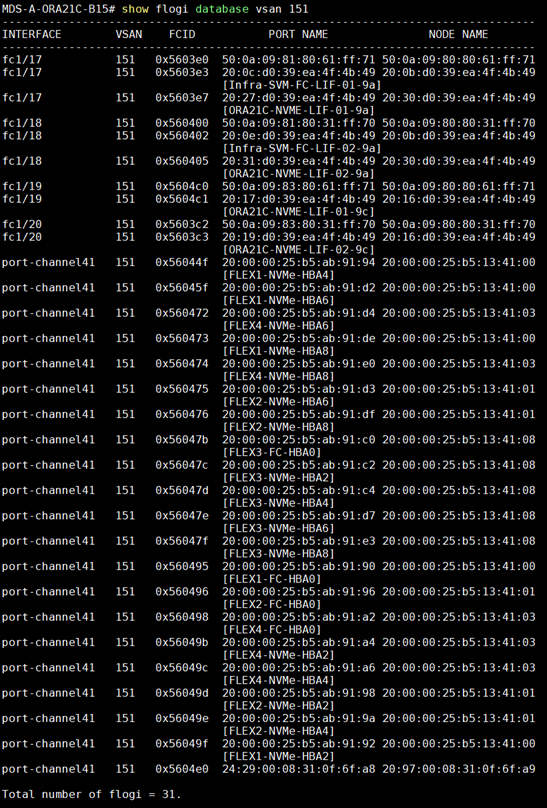
Step 2. Login as admin user into MDS Switch B and verify all “flogi” by running “show flogi database vsan 152” as shown below:
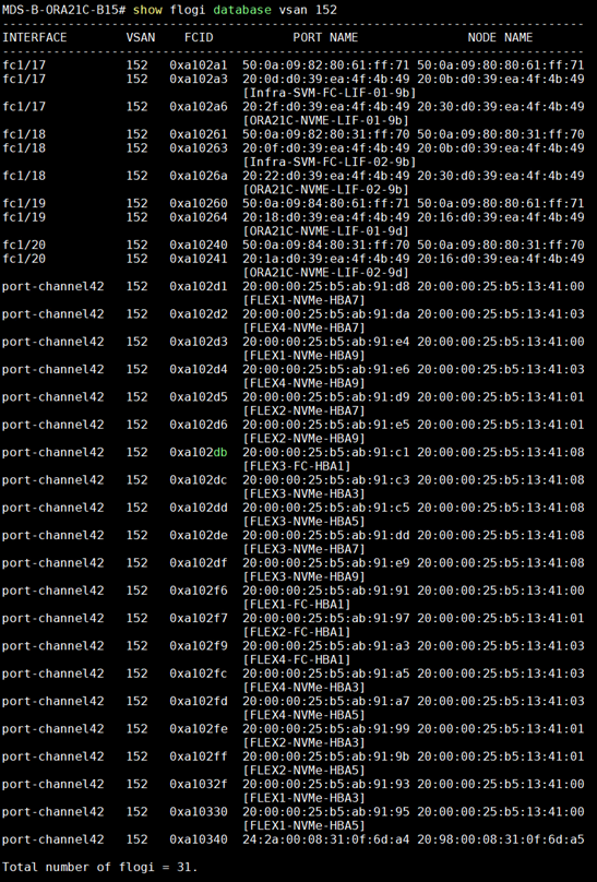
NetApp AFF A900 Storage Configuration
This section details the high-level steps to configure the NetApp Storage for this solution.
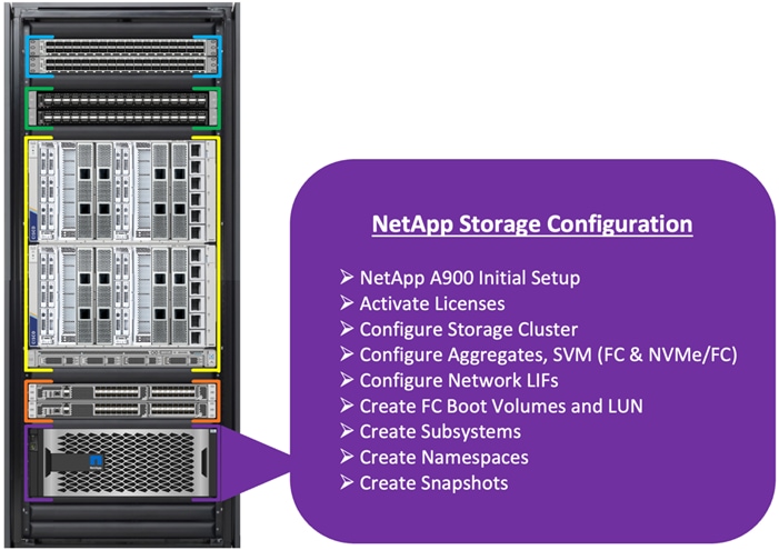
It is beyond the scope of this document to explain the detailed information about the NetApp storage connectivity and infrastructure configuration. For installation and setup instruction for the NetApp AFF A900 System, see:
https://docs.netapp.com/us-en/ontap-systems/a900/install_detailed_guide.html
https://docs.netapp.com/us-en/ontap-systems/a900/install_quick_guide.html
For additional information, go to the Cisco site: https://www.cisco.com/c/en/us/solutions/design-zone/data-center-design-guides/flexpod-design-guides.html
This section describes the storage layout and design considerations for the storage and database deployment. For this solution, the NetApp Storage controller for HA and the storage node failover is configured as shown below:
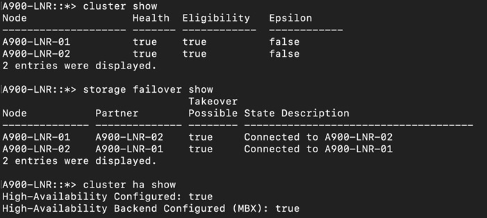
For all the database deployment, two aggregates (one aggregate on each storage node) were configured on each of the storage controller nodes, and each aggregate contains 12 SSD (3.84 TB each) drives that were subdivided into RAID DP groups as shown below:
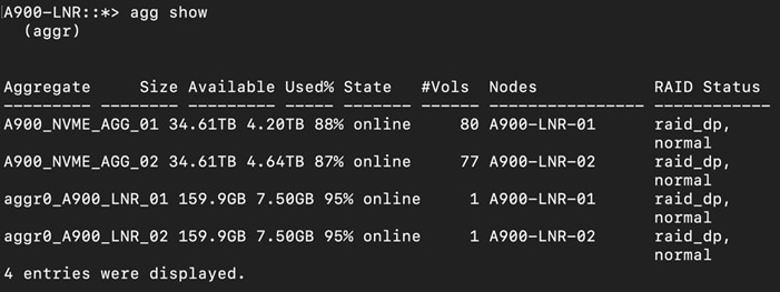
The Storage VMs (formally known as Vserver) configured for this solution is shown below:
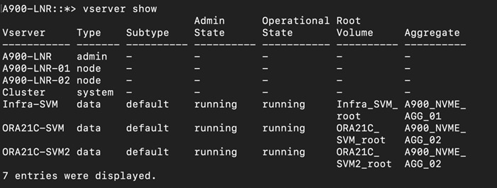
As described in the previous section, one SVM (Infra-SVM) was configured for FC SAN Boot and another two SVM were configured to carry NVMe/FC traffic for database storage traffic. The screenshot below shows the allowed protocols configured for all three SVMs:
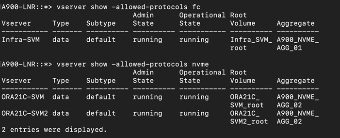
For the FC SVM (Infra-SVM), two FC Logical Interfaces (LIFs) are created on storage controller cluster node 1 (Infra-SVM-FC-LIF-01-9a and Infra-SVM-FC-LIF-01-9b) and two Fibre Channel LIFs are created on storage controller cluster node 2 (Infra-SVM-FC-LIF-02-9a and Infra-SVM-FC-LIF-02-9b) as shown below:
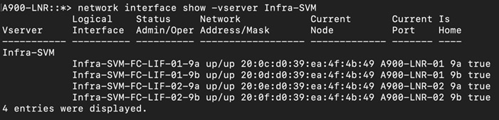
For SVM “ORA21C-SVM”, two NVMe Logical Interfaces (LIFs) are created on storage controller cluster node 1 (ORA21C-NVME-LIF-01-9c and ORA21C-NVME-LIF-01-9d) and two NVMe LIFs are created on storage controller cluster node 2 (ORA21C-NVME-LIF-02-9c and ORA21C-NVME-LIF-02-9d).
To take advantage of all eight FC ports on running NVMe/FC traffic, another NVMe SVM “ORA21C-SVM2” was created. In the second NVMe/FC SVM, two NVMe Logical Interfaces (LIFs) are created on storage controller cluster node 1 (ORA21C-NVME-LIF-01-9a and ORA21C-NVME-LIF-01-9b) and two NVMe LIFs are created on storage controller cluster node 2 (ORA21C-NVME-LIF-02-9a and ORA21C-NVME-LIF-02-9b) as shown below:
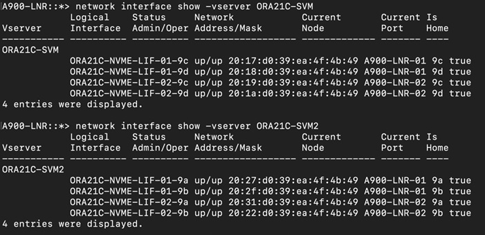
The overview of the network configuration and all the LIFs used in this solution is shown below:

For the storage controller nodes (A900-LNR-01 and A900-LNR-02), ports 9a, 9b and 9c, 9d were used to configure the LIFs. The WWPN of these LIFs are used for zoning into the MDS switches for the storage of the MDS connectivity.
On “Infra-SVM”, four “igroup” were created and added their respective initiators to configure SAN boot for each of the server nodes as shown below:
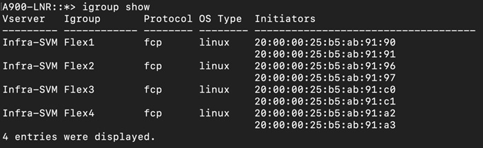
After creating “igroup”, four volumes on this “Infra-SVM” were created. For each volume, one LUN was created, and this LUN was mapped to an individual “igroup” where the OS will be installed, as shown below:
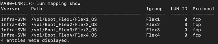
For database deployment, multiple subsystems and namespaces were created. An equal number of subsystems were created on the storage controller by placing those into the aggregate equally.
Operating System and Database Deployment
This chapter contains the following:
· Configure the Operating System
· ENIC and FNIC Drivers for Linux OS
· NVME CLI
· Public and Private Network Interfaces
· Configure OS Prerequisites for Oracle Software
· Configure Additional OS Prerequisites
· NetApp Storage Host Group and Namespaces for OCR and Voting Disk
· Oracle Database 21c GRID Infrastructure Deployment
· Oracle Database Grid Infrastructure Software
· Oracle Database Installation
· Oracle Database Multitenant Architecture
Note: Detailed steps to install the OS are not explained in this document, but the following section describes the high-level steps for an OS install.
The design goal of this reference architecture is to represent a real-world environment as closely as possible.
As explained in the previous section, the service profile was created using Cisco Intersight to rapidly deploy all stateless servers to deploy a four node Oracle RAC. The SAN boot LUNs for these servers were hosted on the NetApp Storage Cluster to provision the OS. The zoning was performed on the Cisco MDS Switches to enable the initiators to discover the targets during the boot process.
Each server node has a dedicated single LUN to install the operating system. For this solution, the Red Hat Enterprise Linux Server 8.7 (4.18.0-425.3.1.el8.x86_64) was installed on these LUNs and the NVMe/FC connectivity was configured, all prerequisite packages were configured to install the Oracle Database 21c Grid Infrastructure, and the Oracle Database 21c software was used to create a four node Oracle Multitenant RAC 21c database for this solution.
The following screenshot shows the high-level steps to configure the Linux Hosts and deploy the Oracle RAC Database solution:
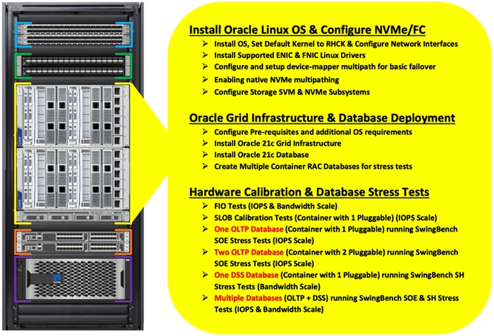
This section describes the high-level steps to configure the Oracle Linux Hosts and deploy the Oracle RAC Database solution.
Configure the Operating System
Note: The detailed installation process is not explained in this document, but the following procedure describes the high-level steps for the OS installation.
Procedure 1. Configure OS
Step 1. Download the Red Hat Enterprise Linux 8.7 OS image and save the IOS file to local disk.
Step 2. Launch the vKVM console on your server by going to Cisco Intersight > Infrastructure Service > Operate > Servers > click Chassis 1 Server 1 > from the Actions drop-down list select Launch vKVM.
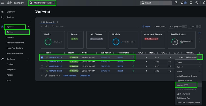
Step 3. Click Accept security and open KVM. Click Virtual Media > vKVM-Mapped vDVD. Click Browse and map the Oracle Linux ISO image, click Open and then click Map Drive. After mapping the iso file, click Power > Power Cycle System to reboot the server.
When the Server boots, it will detect the boot order and start booting from the Virtual mapped DVD as previously configured.
Step 4. When the Server starts booting, it will detect the NetApp Storage active FC paths. If you see those following storage targets in the KVM console while the server is rebooting along with the target WWPNs, it confirms the setup and zoning is done correctly and boot from SAN will be successful
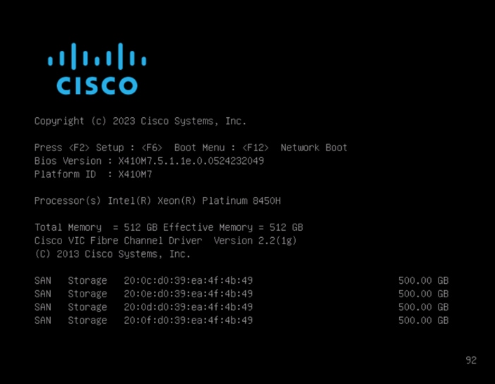
Step 5. During the server boot order, it detects the virtual media connected as RHEL OS ISO DVD media and it will launch the RHEL OS installer.
Step 6. Select language and for the Installation destination assign the local virtual drive. Apply the hostname and click Configure Network to configure any or all the network interfaces. Alternatively, you can configure only the “Public Network” in this step. You can configure additional interfaces as part of post OS install steps.
Note: For an additional RPM package, we recommend selecting the “Customize Now” option and the relevant packages according to your environment.
Step 7. After the OS installation finishes, reboot the server, and complete the appropriate registration steps.
Step 8. Repeat steps 1 – 4 on all server nodes and install RHEL 8.7 to create a four node Linux system.
Step 9. Optionally, you can choose to synchronize the time with ntp server. Alternatively, you can choose to use the Oracle RAC cluster synchronization daemon (OCSSD). Both NTP and OCSSD are mutually exclusive and OCSSD will be setup during GRID install if NTP is not configured.
ENIC and FNIC Drivers for Linux OS
For this solution, the following ENIC and FNIC versions were installed:
· ENIC: version: 4.5.0.7-939.23
· FNIC: version: 2.0.0.90-252.0
Procedure 1. Install the ENIC and FNIC drivers
Step 1. Download the supported UCS Linux Drivers from this link: https://software.cisco.com/download/home/286327804
Step 2. Mount the driver ISO to the Linux host KVM and install the relevant supported ENIC and FNIC drivers for the Linux OS. To configure the drivers, run the following commands:
· Check the current ENIC & FNIC version:
[root@flex1 ~]# cat /sys/module/enic/version
[root@flex1 ~]# cat /sys/module/fnic/version
[root@flex1 ~]# rpm -qa | grep enic
[root@flex1 ~]# rpm -qa | grep fnic
· Install the supported ENIC & FNIC driver from RPM:
[root@flex1 software]# rpm -ivh kmod-enic-4.5.0.7-939.23.rhel8u7_4.18.0_425.3.1.x86_64
[root@flex1 software]# rpm -ivh kmod-fnic-2.0.0.90-252.0.rhel8u7.x86_64
· Reboot the server and verify that the new driver is running as shown below:
[root@flex1 ~]# rpm -qa | grep enic
kmod-enic-4.5.0.7-939.23.rhel8u7_4.18.0_425.3.1.x86_64
[root@flex1 ~]# rpm -qa | grep fnic
kmod-fnic-2.0.0.90-252.0.rhel8u7.x86_64
[root@flex1 ~]# modinfo enic | grep version
version: 4.5.0.7-939.23
rhelversion: 8.7
srcversion: 364BE09AF9AB3D617604981
vermagic: 4.18.0-425.3.1.el8.x86_64 SMP mod_unload modversions
[root@flex1 ~]# modinfo fnic | grep version
version: 2.0.0.90-252.0
rhelversion: 8.7
srcversion: 53636D30625099CEC5870E4
vermagic: 4.18.0-425.3.1.el8.x86_64 SMP mod_unload modversions
[root@flex1 ~]# cat /sys/module/enic/version
4.5.0.7-939.23
[root@flex1 ~]# cat /sys/module/fnic/version
2.0.0.90-252.0
[root@flex1 ~]# lsmod | grep fnic
fnic 286720 8
nvme_fc 53248 1 fnic
scsi_transport_fc 81920 1 fnic
Step 3. Repeat steps 1 and 2 to configure the linux drivers on all nodes.
Note: You should use a matching ENIC and FNIC pair. Check the Cisco UCS supported driver release for more information about the supported kernel version, here: https://www.cisco.com/c/en/us/support/docs/servers-unified-computing/ucs-manager/116349-technote-product-00.html
The NVME hosts and targets are distinguished through their NQN. The FNIC NVME host reads its host nqn from the file /etc/nvme/hostnqn. With a successful installation of the nvme-cli package, the hostnqn file will be created automatically for some OS versions, such as RHEL.
Note: If the /etc/nvme/hostnqn file is not present after name-cli installed, then create the file manually.
Procedure 1. Install the NVME CLI
Step 1. Run the following commands to Install nvme-cli and get HostNQN information from the host:
[root@flex1 ~]# rpm -q nvme-cli
nvme-cli-1.16-5.el8.x86_64
[root@flex1 ~]# cat /etc/nvme/hostnqn
nqn.2014-08.org.nvmexpress:uuid:34010000-4913-0010-0000-134134000000
For this solution, the DM-Multipath was configured only for the FC Boot LUNs. The NVMe/FC Storage path is explained in section Native NVMe Multipathing.
Note: For DM-Multipath Configuration and best practice, refer to NetApp Support: https://library.netapp.com/ecmdocs/ECMP1217221/html/GUID-34FA2578-0A83-4ED3-B4B3-8401703D65A6.html
Note: We made sure the multipathing packages were installed and enabled for an automatic restart across reboots.
Procedure 1. Configure device-mapper multipathing
Step 1. Enable and initialize the multipath configuration file:
[root@flex1 ~]# mpathconf –-enable
[root@flex1 ~]# systemctl status multipathd.service
[root@flex1 ~]# mpathconf
multipath is enabled
find_multipaths is yes
user_friendly_names is enabled
default property blacklist is disabled
enable_foreign is set (foreign multipath devices may not be shown)
dm_multipath module is loaded
multipathd is running
Step 2. Edit the “/etc/multipath.conf” file:
[root@flex1 ~]# cat /etc/multipath.conf
defaults {
find_multipaths yes
user_friendly_names yes
enable_foreign NONE
}
multipaths {
multipath {
wwid 3600a09803831377a522b55652f36796a
alias Flex1_OS
}
}
Note: You must configure “enable_foreign” in “/etc/multipath.conf” for dm-multipath to prevent dm-multipath from claiming NVMe/FC namespace devices. It is recommended using in-kernel NVMe multipath for ONTAP namespaces and dm-multipath for ONTAP LUNs.
Step 3. Run “multipath –ll” command to view all the LUN id and enter that wwid information accordingly on each node:
[root@flex1 ~]# multipath -ll
Flex1_OS (3600a09803831377a522b55652f36796a) dm-0 NETAPP,LUN C-Mode
size=400G features='3 queue_if_no_path pg_init_retries 50' hwhandler='1 alua' wp=rw
|-+- policy='service-time 0' prio=50 status=active
| |- 3:0:0:0 sdb 8:16 active ready running
| `- 4:0:1:0 sde 8:64 active ready running
`-+- policy='service-time 0' prio=10 status=enabled
|- 3:0:1:0 sdc 8:32 active ready running
`- 4:0:0:0 sdd 8:48 active ready running
Non-volatile Memory Express™ (NVMe™) devices support a native multipathing functionality. When configuring multipathing on NVMe, you can select between the standard DM Multipath framework and the native NVMe multipathing.
For this solution, Native Multipathing was enabled and configured for NVMe/FC which is provided by nvme-core.
Procedure 1. Enable native multipathing
Step 1. The default kernel setting for the nvme_core.multipath option is set to “N”, which means that the native Non-volatile Memory Express™ (NVMe™) multipathing is disabled.
Step 2. You can enable native NVMe multipathing using the native NVMe multipathing solution. Check if the native NVMe multipathing is enabled in the kernel:
[root@flex1 ~]# cat /sys/module/nvme_core/parameters/multipath
Step 3. If the native NVMe multipathing is disabled, enable it by adding the settings to the kernel:
[root@flex1 ~]# grubby --update-kernel=ALL --args="nvme_core.multipath=Y"
Step 4. Reboot the node.
Step 5. On the running system, verify the I/O policy on NVMe devices to distribute the I/O on all available paths:
[root@flex1 ~]# cat /sys/module/nvme_core/parameters/multipath
Y
[root@flex1 ~]# cat /sys/class/nvme-subsystem/nvme-subsys*/iopolicy
round-robin
round-robin
round-robin
round-robin
round-robin
round-robin
round-robin
round-robin
Public and Private Network Interfaces
If you have not configured network settings during OS installation, then configure it now. Each node must have at least two network interface cards (NICs), or network adapters. One adapter is for the public network interface and another adapter is for the private network interface (RAC interconnect).
Procedure 1. Configure Management Public and Private Network Interfaces
Step 1. Login as a root user into each Linux node and go to /etc/sysconfig/network-scripts/.
Step 2. Configure the Public network and Private network IP addresses according to your environments.
Note: Configure the Private and Public network with the appropriate IP addresses on all four Linux Oracle RAC nodes.
Procedure 1. Configure subsystems on storage
Step 1. Login as admin user into NetApp Storage Array.
Step 2. Go to Hosts > NVMe Subsystems > and then click +Create.
Note: For this solution, four subsystems were configured on NVMe SVM “ORA21C-SVM” as “ORA21C-SUB1”, “ORA21C-SUB2”, “ORA21C-SUB3” and “ORA21C-SUB4” and four subsystems on NVMe SVM “ORA21C-SVM2” as “PROD-SUB1”, “PROD-SUB2”, “PROD-SUB3” and “PROD-SUB4”. On each of the subsystems, “Linux” for the Host OS and added all four-hosts “hostnqn” as shown below:
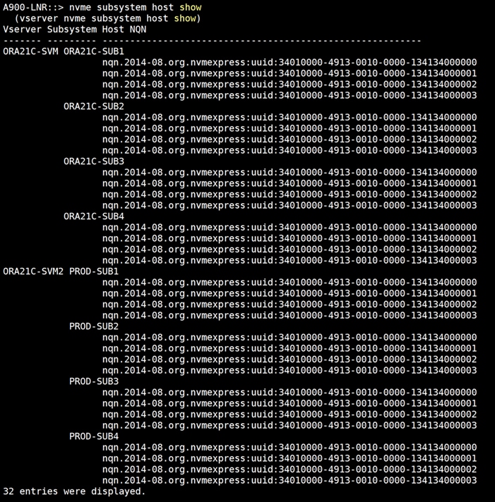
The overview of the subsystem from the NetApp GUI:
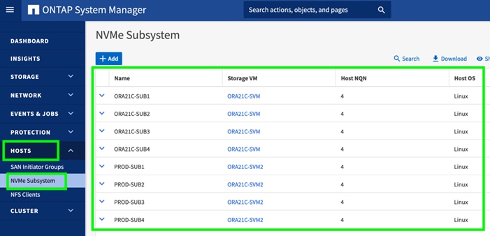
Configure OS Prerequisites for Oracle Software
To successfully install the Oracle RAC Database 21c software, configure the operating system prerequisites on all four Linux nodes.
Note: Follow the steps according to your environment and requirements. For more information, see the Install and Upgrade Guide for Linux for Oracle Database 21c: https://docs.oracle.com/en/database/oracle/oracle-database/21/cwlin/index.html and https://docs.oracle.com/en/database/oracle/oracle-database/21/ladbi/index.html
Procedure 1. Configure the OS prerequisites
Step 1. To configure the operating system prerequisites using RPM for Oracle 21c software on Linux node, install the “oracle-database-preinstall-21c (oracle-database-preinstall-21c-1.0-1.el8.x86_64.rpm)" rpm package on all four nodes. You can also download the required packages from: https://public-yum.oracle.com/oracle-linux-8.html
Step 2. If you plan to use the “oracle-database-preinstall-21c" rpm package to perform all your prerequisites setup automatically, then login as root user and issue the following command on all each of the RAC nodes:
[root@flex1 ~]# yum install oracle-database-preinstall-21c-1.0-1.el8.x86_64.rpm
Note: If you have not used the oracle-database-preinstall-21c package, then you will have to manually perform the prerequisites tasks on all the nodes.
Configure Additional OS Prerequisites
After configuring the automatic or manual prerequisites steps, you have a few additional steps to complete the prerequisites to install the Oracle database software on all four Linux nodes.
Procedure 1. Disable SELinux
Since most organizations might already be running hardware-based firewalls to protect their corporate networks, you need to disabled Security Enhanced Linux (SELinux) and the firewalls at the server level for this reference architecture.
Step 1. Set the secure Linux to permissive by editing the "/etc/selinux/config" file, making sure the SELINUX flag is set as follows:
SELINUX=permissive
Procedure 2. Disable Firewall
Step 1. Check the status of the firewall by running following commands. (The status displays as active (running) or inactive (dead)). If the firewall is active / running, run this command to stop it:
systemctl status firewalld.service
systemctl stop firewalld.service
Step 2. To completely disable the firewalld service so it does not reload when you restart the host machine, run the following command:
systemctl disable firewalld.service
Procedure 3. Create Grid User
Step 1. Run this command to create a grid user:
useradd –u 54322 –g oinstall –G dba grid
Procedure 4. Set the User Passwords
Step 1. Run these commands to change the password for Oracle and Grid Users:
passwd oracle
passwd grid
Procedure 5. Configure UDEV Rules for IO Policy
You need to configure the UDEV rules to assign the IO Policy in all Oracle RAC nodes to access the NetApp Storage subsystems as round-robin.
Step 1. Assign IO Policy by creating a new file named “71-nvme-iopolicy-netapp-ONTAP.rules” with the following entries on all the nodes:
[root@flex1 ~]# cat /etc/udev/rules.d/71-nvme-iopolicy-netapp-ONTAP.rules
### Enable round-robin for NetApp ONTAP
ACTION=="add", SUBSYSTEM=="nvme-subsystem", ATTR{model}=="NetApp ONTAP Controller", ATTR{iopolicy}="round-robin"
Procedure 6. Configure “/etc/hosts”
Step 1. Login as a root user into the Linux node and edit the /etc/hosts file.
Step 2. Provide the details for Public IP Address, Private IP Address, SCAN IP Address, and Virtual IP Address for all the nodes. Configure these settings in each Oracle RAC Nodes as shown below:
[root@flex1 ~]# cat /etc/hosts
127.0.0.1 localhost localhost.localdomain localhost4 localhost4.localdomain4
::1 localhost localhost.localdomain localhost6 localhost6.localdomain6
### Public IP ###
10.29.134.71 flex1 flex1.ciscoucs.com
10.29.134.72 flex2 flex2.ciscoucs.com
10.29.134.73 flex3 flex3.ciscoucs.com
10.29.134.74 flex4 flex4.ciscoucs.com
### Virtual IP ###
10.29.134.75 flex1-vip flex1-vip.ciscoucs.com
10.29.134.76 flex2-vip flex2-vip.ciscoucs.com
10.29.134.77 flex3-vip flex3-vip.ciscoucs.com
10.29.134.78 flex4-vip flex4-vip.ciscoucs.com
### Private IP ###
10.10.10.71 flex1-priv flex1-priv.ciscoucs.com
10.10.10.72 flex2-priv flex2-priv.ciscoucs.com
10.10.10.73 flex3-priv flex3-priv.ciscoucs.com
10.10.10.74 flex4-priv flex4-priv.ciscoucs.com
### SCAN IP ###
10.29.134.79 flex-scan flex-scan.ciscoucs.com
10.29.134.80 flex-scan flex-scan.ciscoucs.com
10.29.134.81 flex-scan flex-scan.ciscoucs.com
[root@flex1 ~]#
Step 3. You must configure the following addresses manually in your corporate setup:
· A Public and Private IP Address for each Linux node
· A Virtual IP address for each Linux node
· Three single client access name (SCAN) address for the oracle database cluster
Note: These steps were performed on all four Linux nodes. These steps complete the prerequisites for the Oracle Database 21c installation at OS level on the Oracle RAC Nodes.
NetApp Storage Host Group and Namespaces for OCR and Voting Disk
You will use the OCRVOTE file system on the storage array to store the OCR (Oracle Cluster Registry) files, Voting Disk files, and other clusterware files.
Procedure 1. Configure the NetApp Storage Host Group and Namespaces for OCR and Voting Disk
Step 1. Login as Admin user into the NetApp array.
Step 2. Go to Storage > NVMe Namespaces > and click +Create.
Note: For this solution, two namespaces were created. Namespace “ocrvote1” was configured on “ORA21C-SUB1” and namespace “ocrvote2” was configured on “ORA21C-SUB2” with each namespace was 100 GB for storing OCR and Voting Disk files for all the RAC databases. Also, each namespace was spread across both the aggregate.
Note: You will create more namespaces for storing database files later in database creation.
Step 3. When the OS level prerequisites and file systems are configured, you are ready to install the Oracle Grid Infrastructure as grid user. Download the Oracle Database 21c (21.3.0.0.0) for Linux x86-64 and the Oracle Database 21c Grid Infrastructure (21.3.0.0.0) for Linux x86-64 software from Oracle Software site. Copy these software binaries to Oracle RAC Node 1 and unzip all files into appropriate directories.
Note: These steps complete the prerequisites for the Oracle Database 21c Installation at OS level on the Oracle RAC Nodes.
Oracle Database 21c GRID Infrastructure Deployment
This section describes the high-level steps for the Oracle Database 21c RAC installation. This document provides a partial summary of details that might be relevant.
Note: It is not within the scope of this document to include the specifics of an Oracle RAC installation; you should refer to the Oracle installation documentation for specific installation instructions for your environment. For more information, click this link for the Oracle Database 21c install and upgrade guide: https://docs.oracle.com/en/database/oracle/oracle-database/21/cwlin/index.html
For this solution, two namespaces of 100G each in size were created and shared across all four Linux nodes for storing OCR and Voting Disk files for all RAC databases. Oracle 21c Release 21.3 Grid Infrastructure (GI) was installed on the first node as a grid user. The installation also configured and added the remaining three nodes as a part of the GI setup. We also configured Oracle Automatic Storage Management (ASM) in Flex mode.
Complete the following procedures to install the Oracle Grid Infrastructure software for the Oracle Standalone Cluster.
Procedure 1. Create Directory Structure
Step 1. Download and copy the Oracle Grid Infrastructure image files to the first local node only. During installation, the software is copied and installed on all other nodes in the cluster.
Step 2. Create the directory structure according to your environment and run the following commands:
For example:
mkdir -p /u01/app/grid
mkdir -p /u01/app/21.3.0/grid
mkdir -p /u01/app/oraInventory
mkdir -p /u01/app/oracle/product/21.3.0/dbhome_1
chown -R grid:oinstall /u01/app/grid
chown -R grid:oinstall /u01/app/21.3.0/grid
chown -R grid:oinstall /u01/app/oraInventory
chown -R oracle:oinstall /u01/app/oracle
Step 3. As the grid user, download the Oracle Grid Infrastructure image files and extract the files into the Grid home:
cd /u01/app/21.3.0/grid
unzip -q <download_location>/LINUX.X64_213000_grid_home.zip
Procedure 2. Configure UDEV Rules for ASM Disk Access
Step 1. Configure the UDEV rules to have read/write privileges on the storage namespaces for grid user. This includes the device details and corresponding “uuid” of the storage namespaces:
Assign Owner & Permission on NVMe Targets by creating a new file named “80-nvme.rules” with the following entries on all the nodes
[root@flex1 ~]# cat /etc/udev/rules.d/80-nvme.rules
#Generated by create_udevrules.py
KERNEL=="nvme[0-99]*n[0-99]*", ENV{DEVTYPE}=="disk", ENV{ID_WWN}=="uuid.d490af5f-cbf1-460a-9b9d-c1e96d3644ff", SYMLINK+="ocrvote1", GROUP:="oinstall", OWNER:="grid", MODE:="660"
KERNEL=="nvme[0-99]*n[0-99]*", ENV{DEVTYPE}=="disk", ENV{ID_WWN}=="uuid.71b0048b-295d-49fb-9dab-b34dedfbba7e", SYMLINK+="ocrvote2", GROUP:="oinstall", OWNER:="grid", MODE:="660"
HugePages
HugePages is a method to have a larger page size that is useful for working with very large memory. For Oracle Databases, using HugePages reduces the operating system maintenance of page states, and increases Translation Lookaside Buffer (TLB) hit ratio.
Advantage of HugePages:
· HugePages are not swappable so there is no page-in/page-out mechanism overhead.
· HugePages uses fewer pages to cover the physical address space, so the size of "bookkeeping"(mapping from the virtual to the physical address) decreases, so it requires fewer entries in the TLB and so TLB hit ratio improves.
· HugePages reduces page table overhead. Also, HugePages eliminates page table lookup overhead: Since the pages are not subject to replacement, page table lookups are not required.
· Faster overall memory performance: On virtual memory systems, each memory operation is two abstract memory operations. Since there are fewer pages to work on, the possible bottleneck on page table access is avoided.
Note: For this configuration, HugePages were used for all the OLTP and DSS workloads. Refer to the Oracle guidelines to configure HugePages: https://docs.oracle.com/en/database/oracle/oracle-database/21/ladbi/disabling-transparent-hugepages.html
Procedure 3. Run Cluster Verification Utility
This procedure verifies that all the prerequisites are met to install the Oracle Grid Infrastructure software. Oracle Grid Infrastructure ships with the Cluster Verification Utility (CVU) that can run to validate the pre and post installation configurations.
Step 1. Login as Grid User in Oracle RAC Node 1 and go to the directory where the Oracle Grid software binaries are located. Run the script named “runcluvfy.sh” as follows:
./runcluvfy.sh stage -pre crsinst -n flex1,flex2,flex3,flex4 –verbose
After the configuration, you are ready to install the Oracle Grid Infrastructure and Oracle Database 21c software.
Note: For this solution, Oracle home binaries were installed on the boot LUN of the nodes. The OCR, Data, and Redo Log files reside in the namespace configured on netapp storage array
Oracle Database Grid Infrastructure Software
Note: It is not within the scope of this document to include the specifics of an Oracle RAC installation. However, a partial summary of details is provided that might be relevant. Please refer to the Oracle installation documentation for specific installation instructions for your environment.
Procedure 1. Install and configure the Oracle Database Grid Infrastructure software
Step 1. Go to the Grid home where the Oracle 21c Grid Infrastructure software binaries are located and launch the installer as the "grid" user.
Step 2. Start the Oracle Grid Infrastructure installer by running the following command:
./gridSetup.sh
Step 3. Select the option Configure Oracle Grid Infrastructure for a New Cluster then click Next.
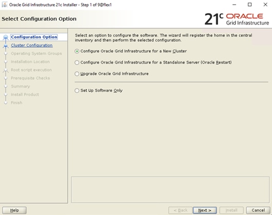
Step 4. For the Cluster Configuration select Configure an Oracle Standalone Cluster then click Next.
Step 5. In next window, enter the Cluster Name and SCAN Name fields. Enter the names for your cluster and cluster scan that are unique throughout your entire enterprise network. You can also select to Configure GNS if you have configured your domain name server (DNS) to send to the GNS virtual IP address name resolution requests.
Step 6. In the Cluster node information window, click Add to add all four nodes, Public Hostname and Virtual Host-name as shown below:
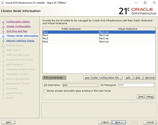
Step 7. You will see all nodes listed in the table of cluster nodes. Click the SSH Connectivity. Enter the operating system username and password for the Oracle software owner (grid). Click Setup.
Step 8. A message window appears, indicating that it might take several minutes to configure SSH connectivity between the nodes. After some time, another message window appears indicating that password-less SSH connectivity has been established between the cluster nodes. Click OK to continue.
Step 9. In the Network Interface Usage screen, select the usage type for each network interface for Public and Private Network Traffic and click Next.
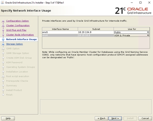
Step 10. In the storage option, select the option Use Oracle Flex ASM for storage then click Next. For this solution, the Do Not Use a GIMR database option was selected.
Step 11. In the Create ASM Disk Group window, select the “ocrvote1” & “ocrvote2” namespaces which are configured into NetApp Storage to store OCR and Voting disk files. Enter the name of disk group “OCRVOTE” and select appropriate external redundancy options as shown below:
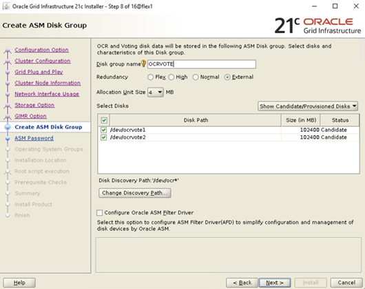
Note: For this solution, we did not configure Oracle ASM Filter Driver.
Step 12. Select the password for the Oracle ASM account, then click Next:
Step 13. For this solution, “Do not use Intelligent Platform Management Interface (IPMI)” was selected. Click Next.
Step 14. You can configure to have this instance of the Oracle Grid Infrastructure and Oracle Automatic Storage Management to be managed by Enterprise Manager Cloud Control. For this solution, this option was not selected. You can choose to set it up according to your requirements.
Step 15. Select the appropriate operating system group names for Oracle ASM according to your environments.
Step 16. Specify the Oracle base and inventory directory to use for the Oracle Grid Infrastructure installation and then click Next. The Oracle base directory must be different from the Oracle home directory. Click Next and select the Inventory Directory according to your setup.
Step 17. Click Automatically run configuration scripts to run scripts automatically and enter the relevant root user credentials. Click Next.
Step 18. Wait while the prerequisite checks complete.
Step 19. If you have any issues, click the "Fix & Check Again." If any of the checks have a status of Failed and are not fixable, then you must manually correct these issues. After you have fixed the issue, you can click Check Again to have the installer check the requirement and update the status. Repeat as needed until all the checks have a status of Succeeded. Click Next.
Step 20. Review the contents of the Summary window and then click Install. The installer displays a progress indicator enabling you to monitor the installation process.
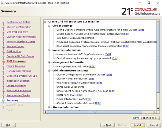
Step 21. Wait for the grid installer configuration assistants to complete.
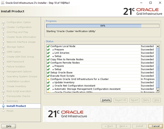
Step 22. When the configuration completes successfully, click Close to finish, and exit the grid installer.
Step 23. When the GRID installation is successful, login to each of the nodes and perform the minimum health checks to make sure that the Cluster state is healthy. After your Oracle Grid Infrastructure installation is complete, you can install Oracle Database on a cluster.
Oracle ASM is Oracle's recommended storage management solution that provides an alternative to conventional volume managers, file systems, and raw devices. Oracle ASM is a volume manager and a file system for Oracle Database files that reduces the administrative overhead for managing database storage by consolidating data storage into a small number of disk groups. The smaller number of disk groups consolidates the storage for multiple databases and provides for improved I/O performance.
Oracle Flex ASM enables an Oracle ASM instance to run on a separate physical server from the database servers. With this deployment, larger clusters of Oracle ASM instances can support more database clients while reducing the Oracle ASM footprint for the overall system.
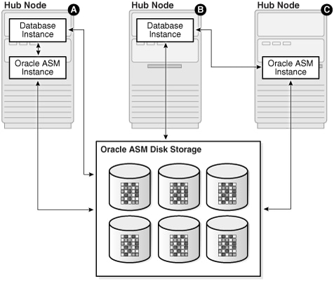
When using Oracle Flex ASM, Oracle ASM clients are configured with direct access to storage. With Oracle Flex ASM, you can consolidate all the storage requirements into a single set of disk groups. All these disk groups are mounted by and managed by a small set of Oracle ASM instances running in a single cluster. You can specify the number of Oracle ASM instances with a cardinality setting. The default is three instances.
The following screenshot shows few more commands to check the cluster and FLEX ASM details:
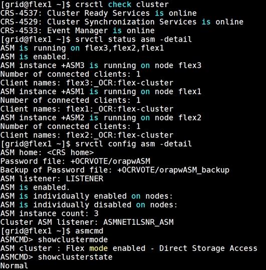
After successfully installing the Oracle GRID, it’s recommended to only install the Oracle Database 21c software. You can create databases using DBCA or database creation scripts at later stage.
Note: It is not within the scope of this document to include the specifics of an Oracle RAC database installation. However, a partial summary of details is provided that might be relevant. Please refer to the Oracle database installation documentation for specific installation instructions for your environment here: https://docs.oracle.com/en/database/oracle/oracle-database/21/ladbi/index.html
Procedure 1. Install Oracle database software
Complete the following steps as an oracle user.
Step 1. Start the “./runInstaller” command from the Oracle Database 21c installation media where the Oracle database software is located.
Step 2. For Configuration Option, select the option Set Up Software Only.
Step 3. Select the option "Oracle Real Application Clusters database installation" and click Next.
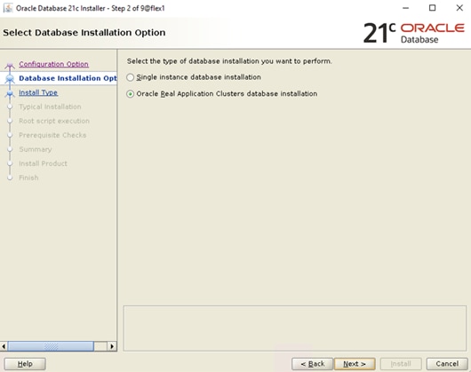
Step 4. Select all four nodes in the cluster where the installer should install Oracle RAC. For this setup, install the software on all four nodes as shown below:
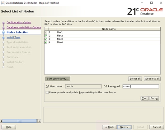
Step 5. Click "SSH Connectivity..." and enter the password for the "oracle" user. Click Setup to configure passwordless SSH connectivity and click Test to test it when it is complete. When the test is complete, click Next.
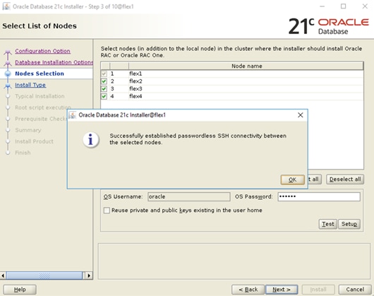
Step 6. Select the Database Edition Options according to your environments and then click Next.
Step 7. Enter the appropriate Oracle Base, then click Next.
Step 8. Select the desired operating system groups and then click Next.
Step 9. Select the option Automatically run configuration script from the option Root script execution menu and click Next.
Step 10. Wait for the prerequisite check to complete. If there are any problems, click "Fix & Check Again" or try to fix those by checking and manually installing required packages. Click Next.
Step 11. Verify the Oracle Database summary information and then click Install.
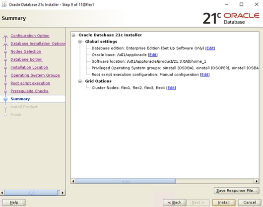
Step 12. Wait for the installation of Oracle Database finish successfully, then click Close to exit of the installer.
These steps complete the installation of the Oracle 21c Grid Infrastructure and Oracle 21c Database software.
Oracle Database Multitenant Architecture
The multitenant architecture enables an Oracle database to function as a multitenant container database (CDB). A CDB includes zero, one, or many customer-created pluggable databases (PDBs). A PDB is a portable collection of schemas, schema objects, and non-schema objects that appears to an Oracle Net client as a non-CDB. All Oracle databases before Oracle Database 12c were non-CDBs.
A container is logical collection of data or metadata within the multitenant architecture. The following figure represents possible containers in a CDB:
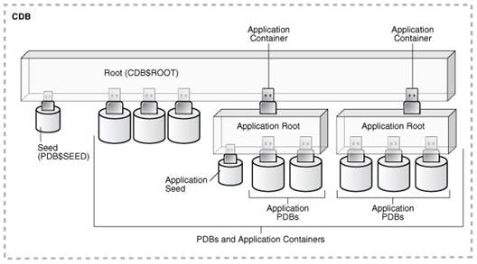
The multitenant architecture solves several problems posed by the traditional non-CDB architecture. Large enterprises may use hundreds or thousands of databases. Often these databases run on different platforms on multiple physical servers. Because of improvements in hardware technology, especially the increase in the number of CPUs, servers can handle heavier workloads than before. A database may use only a fraction of the server hardware capacity. This approach wastes both hardware and human resources. Database consolidation is the process of consolidating data from multiple databases into one database on one computer. The Oracle Multitenant option enables you to consolidate data and code without altering existing schemas or applications.
For more information on Oracle Database Multitenant Architecture, go to: https://docs.oracle.com/en/database/oracle/oracle-database/21/cncpt/CDBs-and-PDBs.html#GUID-5C339A60-2163-4ECE-B7A9-4D67D3D894FB
In this solution, multiple Container Databases were configured and validated system performance as explained in the next scalability test section.
Now you are ready to run synthetic IO tests against this infrastructure setup. “fio” was used as primary tools for IOPS tests.
Scalability Test and Results
This chapter contains the following:
· Hardware Calibration Test using FIO
· IOPS Tests on Single x410c M7 Server
· One OLTP Database Performance
· Multiple (Two) OLTP Databases Performance
· One DSS Database Performance
· Multiple OLTP and DSS Databases Performance
Note: Before creating databases for workload tests, it is extremely important to validate that this is indeed a balanced configuration that can deliver expected performance. In this solution, node and user scalability will be tested and validated on all 4 node Oracle RAC Databases with various database benchmarking tools.
Hardware Calibration Test using FIO
FIO is short for Flexible IO, a versatile IO workload generator. FIO is a tool that will spawn number of threads or processes doing a particular type of I/O action as specified by the user. For this solution, FIO is used to measure the performance of a NetApp storage device over a given period.
For the FIO Tests, we have created 8 Subsystems with total 32 Namespaces (each subsystem having 4 Namespaces) and each of the subsystem was 500 GB in size equally distributed across both the aggregates. These 32 Namespace were shared across all the four nodes for read/write IO operations.
We run various FIO tests for measuring IOPS, Latency and Throughput performance of this solution by changing block size parameter into the FIO test. For each FIO test, we also changed read/write ratio as 0/100 % read/write, 50/50 % read/write, 70/30 % read/write, 90/10 % read/write and 100/0 % read/write to scale the performance of the system. We also ran each of the tests for at least 4 hours to help ensure that this configuration is capable of sustaining this type of load for longer period of time.
IOPS Tests on Single x410c M7 Server
For this single server node IOPS scale, we used FIO with random read/write tests, changed read/write ratio and captured all the output as shown in the chart below:
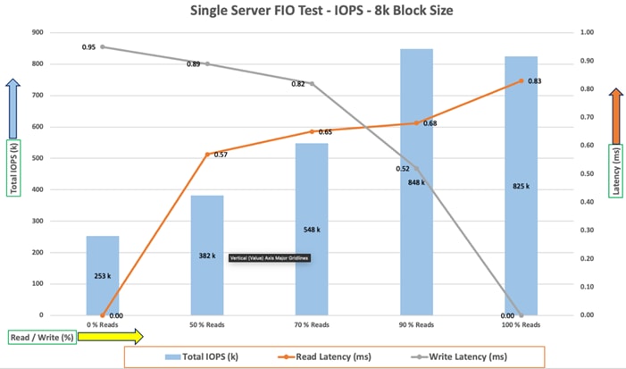
For the single server node, we observed average 825k IOPS for 100/0 % read/write test Cwith the read latency under 1 millisecond. Similarly, for the 90/10 % read/write test, we achieved around 848k IOPS with the read and write latency under 1 millisecond. For the 70/30 % read/write test, we achieved around 548k IOPS with the read and write latency under 1 millisecond. For the 50/50 % read/write test, we achieved around 382k IOPS and for the 0/100 % read/write test, we achieved around 253k IOPS with the write and read latency under 1 millisecond.
The chart below shows results for the same 8k random read/write FIO tests across all four server nodes:
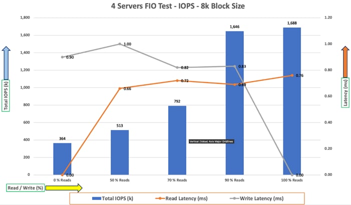
For 8k random read/write IOPS tests across all four-server node, we observed average 1688k IOPS for 100/0 % read/write test with the read latency under 1 millisecond. Similarly, for the 90/10 % read/write test, we achieved around 1645k IOPS with the read and write latency under 1 millisecond. For the 70/30 % read/write test, we achieved around 792k IOPS. For the 50/50 % read/write test, we achieved around 513k IOPS and for the 0/100 % read/write test, we achieved around 364k IOPS with the write and read latency under 1 millisecond.
The following screenshot was captured during 8k random 100/0 % read/write test from netapp which shows the total IOPS with latency while running this test:
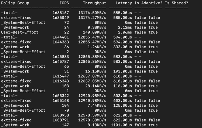
Reads and writes consume system resources differently. The above FIO tests for the 8k block size representing OLTP type of workloads.
The bandwidth tests are carried out with sequential 512k IO Size and represents the DSS database type workloads. The chart below shows results for the various sequential read/write FIO test for the 512k block size. We ran bandwidth test on single x410c M7 server and captured the results as shown below:
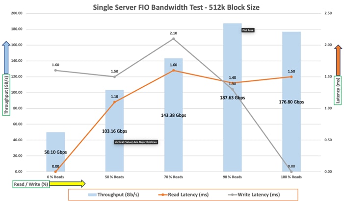
For the 100/0 % read/write test, we achieved around 176 Gbps throughput with the read latency around 1.5 millisecond. Similarly, for the 90/10 % read/write test, we achieved around 187 Gbps throughput with the read and write latency under 2 milliseconds. For the 70/30 % read/write bandwidth test, we achieved around 143 Gbps throughput with the read latency around 1.6 milliseconds while the write latency around 2.1milliseconds. For the 50/50 % read/write test, we achieved around 103 Gbps throughput with the read and write latency under 2 milliseconds And lastly, for the 0/100 % read/write test, we achieved around 50 Gbps throughput with the write latency around 1.6 millisecond.
The following screenshot was captured during 512k sequential random 90/10 % read/write test from netapp which shows the total throughput and latency while running test:
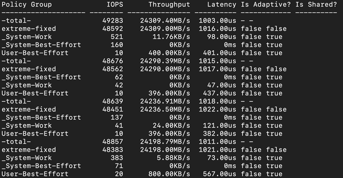
The system under test benefited from slightly better resource distribution in the 90/10 R/W test, resulting in slightly improved peak bandwidth in this test compared with the 100/0 R/W test. We did not see any performance dips or degradation over the period of run time. It is also important to note that this is not a benchmarking exercise, and these are practical and out of box test numbers that can be easily reproduced by anyone. At this time, we are ready to create OLTP database(s) and continue with database tests.
We used Oracle Database Configuration Assistant (DBCA) to create multiple OLTP and DSS databases for SLOB and SwingBench test calibration. For SLOB Tests, we configured one container database as “SLOBCDB” and under this container, we create one pluggable database as “SLOBPDB.” For SwingBench SOE (OLTP type) workload tests, we configured two container databases as “SOECDB” and “ENGCDB”. Under these containers, we created one pluggable database as “SOEPDB” and “ENGPDB” to demonstrate the system scalability running multiple OLTP databases for various SOE workloads. For SwingBench SH (DSS type) workload tests, we configured one container database as “SHCDB” and under this container, we created one pluggable database as “SHPDB.” Alternatively, you can use Database creation scripts to create the databases as well.
For the database deployment, we configured two aggregates (one aggregate on each storage node), and each aggregate contains 11 SSD (3.84 TB Each) drives that were subdivided into RAID DP groups, plus one spare drive as explained earlier in the storage configuration section.
For each RAC database, we created total number of 20 Namespaces. We distributed equal number of namespaces on the storage nodes by placing those namespaces into both the aggregates. All database files were also spread evenly across the two nodes of the storage system so that each storage node served data for the databases. The table below shows the storage layout of all the namespaces configuration for all the databases. For each database, we created two disk groups to store the “data” and “redolog” files for storing the database files. We used 16 namespaces to create Oracle ASM “Data” disk group and 4 namespaces to create Oracle ASM “redolog” disk group for each database.
Table 13 lists the database volume configuration for this solution where we deployed all three databases to validate SLOB and SwingBench workloads.
Table 13. Database volume configuration
| Database Name |
Namespace |
Size (GB) |
Aggregate |
Subsystem |
Notes |
| OCRVOTE |
ocrvote1 |
100 |
A900_NVME_AGG_01 |
ORA21C-SUB1 |
OCR & Voting Disk |
| ocrvote2 |
100 |
A900_NVME_AGG_02 |
ORA21C-SUB2 |
||
|
SLOBCDB (Container SLOBCDB with Pluggable Database as SLOBPDB) |
slobdata01 |
400 |
A900_NVME_AGG_01 |
ORA21C-SUB1 |
SLOB Database Data Files |
| slobdata02 |
400 |
A900_NVME_AGG_02 |
ORA21C-SUB2 |
||
| slobdata03 |
400 |
A900_NVME_AGG_01 |
ORA21C-SUB3 |
||
| slobdata04 |
400 |
A900_NVME_AGG_02 |
ORA21C-SUB4 |
||
| slobdata05 |
400 |
A900_NVME_AGG_01 |
ORA21C-SUB1 |
||
| slobdata06 |
400 |
A900_NVME_AGG_02 |
ORA21C-SUB2 |
||
| slobdata07 |
400 |
A900_NVME_AGG_01 |
ORA21C-SUB3 |
||
| slobdata08 |
400 |
A900_NVME_AGG_02 |
ORA21C-SUB4 |
||
| slobdata09 |
400 |
A900_NVME_AGG_01 |
ORA21C-SUB1 |
||
| slobdata10 |
400 |
A900_NVME_AGG_02 |
ORA21C-SUB2 |
||
| slobdata11 |
400 |
A900_NVME_AGG_01 |
ORA21C-SUB3 |
||
| slobdata12 |
400 |
A900_NVME_AGG_02 |
ORA21C-SUB4 |
||
| slobdata13 |
400 |
A900_NVME_AGG_01 |
ORA21C-SUB1 |
||
| slobdata14 |
400 |
A900_NVME_AGG_02 |
ORA21C-SUB2 |
||
| slobdata15 |
400 |
A900_NVME_AGG_01 |
ORA21C-SUB3 |
||
| slobdata16 |
400 |
A900_NVME_AGG_02 |
ORA21C-SUB4 |
||
| sloblog01 |
50 |
A900_NVME_AGG_01 |
ORA21C-SUB1 |
SLOB Database Redo Log Files |
|
| sloblog02 |
50 |
A900_NVME_AGG_02 |
ORA21C-SUB2 |
||
| sloblog03 |
50 |
A900_NVME_AGG_01 |
ORA21C-SUB3 |
||
| sloblog04 |
50 |
A900_NVME_AGG_02 |
ORA21C-SUB4 |
||
|
SOECDB (Container SOECDB with One Pluggable Database as SOEPDB) |
soedata01 |
1500 |
A900_NVME_AGG_01 |
ORA21C-SUB1 |
SOECDB Database Data Files |
| soedata02 |
1500 |
A900_NVME_AGG_02 |
ORA21C-SUB2 |
||
| soedata03 |
1500 |
A900_NVME_AGG_01 |
ORA21C-SUB3 |
||
| soedata04 |
1500 |
A900_NVME_AGG_02 |
ORA21C-SUB4 |
||
| soedata05 |
1500 |
A900_NVME_AGG_01 |
ORA21C-SUB1 |
||
| soedata06 |
1500 |
A900_NVME_AGG_02 |
ORA21C-SUB2 |
||
| soedata07 |
1500 |
A900_NVME_AGG_01 |
ORA21C-SUB3 |
||
| soedata08 |
1500 |
A900_NVME_AGG_02 |
ORA21C-SUB4 |
||
| soedata09 |
1500 |
A900_NVME_AGG_01 |
ORA21C-SUB1 |
||
| soedata10 |
1500 |
A900_NVME_AGG_02 |
ORA21C-SUB2 |
||
| soedata11 |
1500 |
A900_NVME_AGG_01 |
ORA21C-SUB3 |
||
| soedata12 |
1500 |
A900_NVME_AGG_02 |
ORA21C-SUB4 |
||
| soedata13 |
1500 |
A900_NVME_AGG_01 |
ORA21C-SUB1 |
||
| soedata14 |
1500 |
A900_NVME_AGG_02 |
ORA21C-SUB2 |
||
| soedata15 |
1500 |
A900_NVME_AGG_01 |
ORA21C-SUB3 |
||
| soedata16 |
1500 |
A900_NVME_AGG_02 |
ORA21C-SUB4 |
||
| soelog01 |
100 |
A900_NVME_AGG_01 |
ORA21C-SUB1 |
SOECDB Database Redo Log Files |
|
| soelog02 |
100 |
A900_NVME_AGG_02 |
ORA21C-SUB2 |
||
| soelog03 |
100 |
A900_NVME_AGG_01 |
ORA21C-SUB3 |
||
| soelog4 |
100 |
A900_NVME_AGG_02 |
ORA21C-SUB4 |
||
|
ENGCDB (Container ENGCDB with One Pluggable Database as PDB) |
engdata01 |
1000 |
A900_NVME_AGG_01 |
PROD-SUB1 |
ENGCDB Database Data Files |
| engdata02 |
1000 |
A900_NVME_AGG_02 |
PROD-SUB2 |
||
| engdata03 |
1000 |
A900_NVME_AGG_01 |
PROD-SUB3 |
||
| engdata04 |
1000 |
A900_NVME_AGG_02 |
PROD-SUB4 |
||
| engdata05 |
1000 |
A900_NVME_AGG_01 |
PROD-SUB1 |
||
| engdata06 |
1000 |
A900_NVME_AGG_02 |
PROD-SUB2 |
||
| engdata07 |
1000 |
A900_NVME_AGG_01 |
PROD-SUB3 |
||
| engdata08 |
1000 |
A900_NVME_AGG_02 |
PROD-SUB4 |
||
| engdata09 |
1000 |
A900_NVME_AGG_01 |
PROD-SUB1 |
||
| engdata10 |
1000 |
A900_NVME_AGG_02 |
PROD-SUB2 |
||
| engdata11 |
1000 |
A900_NVME_AGG_01 |
PROD-SUB3 |
||
| engdata12 |
1000 |
A900_NVME_AGG_02 |
PROD-SUB4 |
||
| engdata13 |
1000 |
A900_NVME_AGG_01 |
PROD-SUB1 |
||
| engdata14 |
1000 |
A900_NVME_AGG_02 |
PROD-SUB2 |
||
| engdata15 |
1000 |
A900_NVME_AGG_01 |
PROD-SUB3 |
||
| engdata16 |
1000 |
A900_NVME_AGG_02 |
PROD-SUB4 |
||
| englog01 |
100 |
A900_NVME_AGG_01 |
PROD-SUB1 |
ENGCDB Database Redo Log Files |
|
| englog02 |
100 |
A900_NVME_AGG_02 |
PROD-SUB2 |
||
| englog03 |
100 |
A900_NVME_AGG_01 |
PROD-SUB3 |
||
| englog04 |
100 |
A900_NVME_AGG_02 |
PROD-SUB4 |
||
|
SHCDB (Container SHCDB with One Pluggable Database as SHPDB) |
shdata01 |
800 |
A900_NVME_AGG_01 |
ORA21C-SUB1 |
SH Database Data Files |
| shdata02 |
800 |
A900_NVME_AGG_02 |
ORA21C-SUB2 |
||
| shdata03 |
800 |
A900_NVME_AGG_01 |
ORA21C-SUB3 |
||
| shdata04 |
800 |
A900_NVME_AGG_02 |
ORA21C-SUB4 |
||
| shdata05 |
800 |
A900_NVME_AGG_01 |
ORA21C-SUB1 |
||
| shdata06 |
800 |
A900_NVME_AGG_02 |
ORA21C-SUB2 |
||
| shdata07 |
800 |
A900_NVME_AGG_01 |
ORA21C-SUB3 |
||
| shdata08 |
800 |
A900_NVME_AGG_02 |
ORA21C-SUB4 |
||
| shdata09 |
800 |
A900_NVME_AGG_01 |
ORA21C-SUB1 |
||
| shdata10 |
800 |
A900_NVME_AGG_02 |
ORA21C-SUB2 |
||
| shdata11 |
800 |
A900_NVME_AGG_01 |
ORA21C-SUB3 |
||
| shdata12 |
800 |
A900_NVME_AGG_02 |
ORA21C-SUB4 |
||
| shdata13 |
800 |
A900_NVME_AGG_01 |
ORA21C-SUB1 |
||
| shdata14 |
800 |
A900_NVME_AGG_02 |
ORA21C-SUB2 |
||
| shdata15 |
800 |
A900_NVME_AGG_01 |
ORA21C-SUB3 |
||
| shdata16 |
800 |
A900_NVME_AGG_02 |
ORA21C-SUB4 |
||
| shlog01 |
50 |
A900_NVME_AGG_01 |
ORA21C-SUB1 |
SH Database Redo Log Files |
|
| shlog02 |
50 |
A900_NVME_AGG_02 |
ORA21C-SUB2 |
||
| shlog03 |
50 |
A900_NVME_AGG_01 |
ORA21C-SUB3 |
||
| shlog04 |
50 |
A900_NVME_AGG_02 |
ORA21C-SUB4 |
We used the widely adopted SLOB and Swingbench database performance test tools to test and validate throughput, IOPS, and latency for various test scenarios as explained in the following section.
The Silly Little Oracle Benchmark (SLOB) is a toolkit for generating and testing I/O through an Oracle database. SLOB is very effective in testing the I/O subsystem with genuine Oracle SGA-buffered physical I/O. SLOB supports testing physical random single-block reads (db file sequential read) and random single block writes (DBWR flushing capability). SLOB issues single block reads for the read workload that are generally 8K (as the database block size was 8K).
For testing the SLOB workload, we have created one container database as SLOBCDB. For SLOB database, we have created total 20 namespace. On these 20 namespaces, we have created two disk groups to store the “data” and “redolog” files for the SLOB database. First disk-group “SLOBDATA” was created with 16 namespaces (400 GB each) while second disk-group “SLOBLOG” was created with 4 namespaces (50 GB each).
Those ASM disk groups provided the storage required to create the tablespaces for the SLOB Database. We loaded SLOB schema on “DATASLOB” disk-group of up to 3 TB in size.
We used SLOB2 to generate our OLTP workload. Each database server applied the workload to Oracle database, log, and temp files. The following tests were performed and various metrics like IOPS and latency were captured along with Oracle AWR reports for each test scenario.
SLOB2 was configured to run against all the four Oracle RAC nodes and the concurrent users were equally spread across all the nodes. We tested the environment by increasing the number of Oracle users in database from a minimum of 128 users up to a maximum of 512 users across all the nodes. At each load point, we verified that the storage system and the server nodes could maintain steady-state behavior without any issues. We also made sure that there were no bottlenecks across servers or networking systems.
The User Scalability test was performed with 128, 256, 384 and 512 users on 4 Oracle RAC nodes by varying read/write ratio as follows:
· 100% read (0% update)
· 90% read (10% update)
· 70% read (30% update)
· 50% read (50% update)
Table 14 lists the total number of IOPS (both read and write) available for user scalability test when run with 128, 256, 384 and 512 Users on the SLOB database.
Table 14. Total number of IOPS
| Users |
Read/Write % (100-0) |
Read/Write % (90-10) |
Read/Write % (70-30) |
Read/Write % (50-50) |
| 128 |
721,407 |
740,630 |
813,435 |
879,413 |
| 256 |
1,210,330 |
1,254,877 |
1,302,894 |
1,164,183 |
| 384 |
1,530,944 |
1,554,085 |
1,517,070 |
1,148,786 |
| 512 |
1,580,746 |
1,681,986 |
1,507,301 |
1,097,828 |
The following graphs demonstrate the total number of IOPS while running SLOB workload for various concurrent users for each test scenario.
The graph below shows the linear scalability with increased users and similar IOPS from 128 users to 512 users with 100% Read/Write, 90% Read/Write, 70% Read/Write and 50% Read/Write.
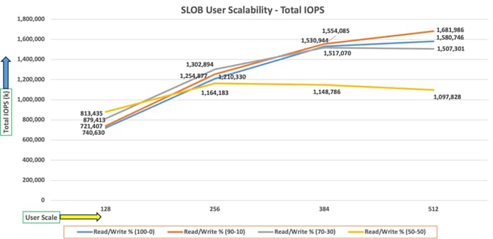
Due to variations in workload randomness, we conducted multiple runs to ensure consistency in behavior and test results.
The AWR screenshot below was captured from one of the test run scenarios for 90% Read (10% update) with 512 users running SLOB workload for sustained 24 hours across all four nodes.
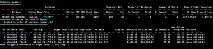
The following screenshot shows a section from the Oracle AWR report that highlights Physical Reads/Sec and Physical Writes/Sec for each instance while running SLOB workload for sustained 24 hours. It highlights that IO load is distributed across all the cluster nodes performing workload operations.
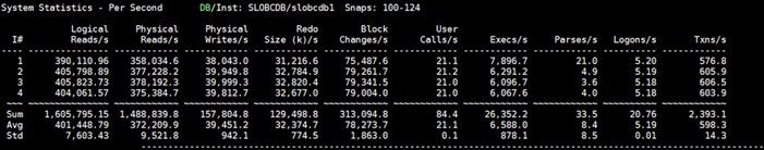
The following screenshot shows “IO Profile” which was captured from the same 90% Read (10% update) Test scenario while running SLOB test with 512 users which shows 1,645,895k IOPS (1,488,865k Reads and 157,030 Writes) for this sustained 24 Hours test.
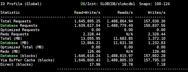
The following screenshot shows “Top Timed Events” and “Wait Time” during this 24 Hour SLOB test while running workload with 512 users for 90% Read (10% update).
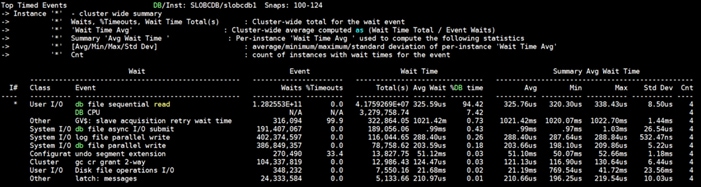
The following screenshot was captured from NetApp GUI during this 24 Hour SLOB test while running workload with 512 users for 90% Read (10% update).
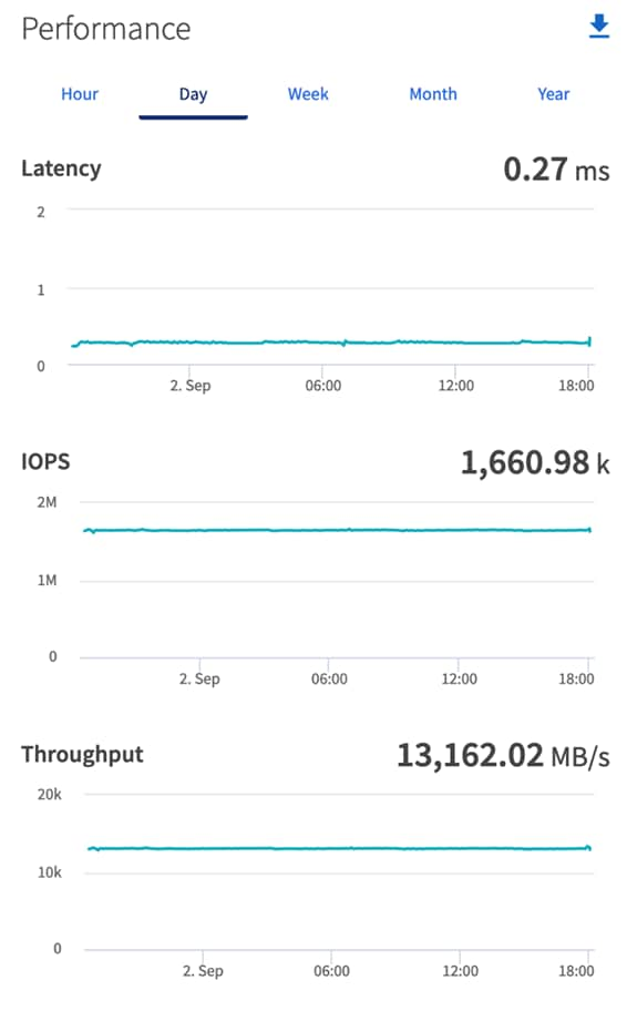
The following screenshot was captured from NetApp command line during this 24 Hour SLOB test which shows IOPS, Throughput and Latency while running workload with 512 users for 90% Read (10% update).
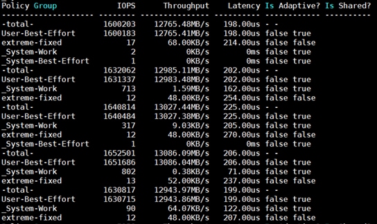
The following graph illustrates the latency exhibited by the NetApp AFF A900 Storage across different workloads (100% Read/Write, 90% Read/Write, 70% Read/Write and 50% Read/Write). All the workloads experienced less than 1 millisecond latency and it varies based on the workloads. As expected, the 50% read (50% update) test exhibited higher latencies as the user counts increases.
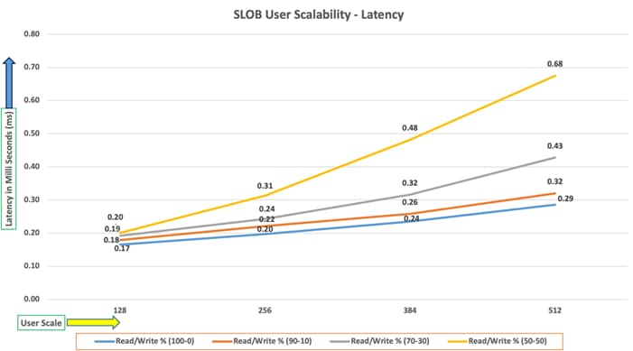
SwingBench is a simple to use, free, Java-based tool to generate various types of database workloads and perform stress testing using different benchmarks in Oracle database environments. SwingBench can be used to demonstrate and test technologies such as Real Application Clusters, Online table rebuilds, Standby databases, online backup, and recovery, and so on. In this solution, we used SwingBench tool for running various type of workload and check the overall performance of this reference architecture.
SwingBench provides four separate benchmarks, namely, Order Entry, Sales History, Calling Circle, and Stress Test. For the tests described in this solution, SwingBench Order Entry (SOE) benchmark was used for representing OLTP type of workload and the Sales History (SH) benchmark was used for representing DSS type of workload.
The Order Entry benchmark is based on SOE schema and is TPC-C like by types of transactions. The workload uses a very balanced read/write ratio around 60/40 and can be designed to run continuously and test the performance of a typical Order Entry workload against a small set of tables, producing contention for database resources.
The Sales History benchmark is based on the SH schema and is like TPC-H. The workload is query (read) centric and is designed to test the performance of queries against large tables.
The first step after the databases creation is calibration; about the number of concurrent users, nodes, throughput, IOPS and latency for database optimization. For this solution, we ran the SwingBench workloads on various combination of databases and captured the system performance as follows:
Typically encountered in the real-world deployments, we tested a combination of scalability and stress related scenarios that ran across all the 8-node Oracle RAC cluster, as follows:
· OLTP database user scalability workload representing small and random transactions.
· DSS database workload representing larger transactions.
· Mixed databases (OLTP and DSS) workloads running simultaneously.
For this SwingBench workload tests, we created three Container Database as SOECDB, ENGCDB and SHCDB. We configured the first container database as “SOECDB” and created one pluggable databases as “SOEPDB” and second container database “ENGCDB” with one pluggable database as “ENGPDB” to run the SwingBench SOE workload representing OLTP type of workload characteristics. We configured the container databases “SHCDB” and created one pluggable databases as “SHPDB” to run the SwingBench SH workload representing DSS type of workload characteristics.
For this solution, we deployed and validated multiple container databases as well as pluggable databases and run various SwingBench SOE and SH workloads to demonstrate the multitenancy capability, performance, and sustainability for this reference architecture.
For the OLTP databases, we created and configured SOE schema of 3.5 TB for the SOEPDB Database and 3 TB for the ENGPDB Database. For the DSS database, we created and configured SH schema of 4 TB for the SHPDB Database:
· One OLTP Database Performance
· Multiple (Two) OLTP Databases Performance
· One DSS Database Performance
· Multiple OLTP & DSS Databases Performance
For one OLTP database workload featuring Order Entry schema, we created one container database SOECDB and one pluggable database SOEPDB as explained earlier. We used 64 GB size of SGA for this database and, we ensured that the HugePages were in use. We ran the SwingBench SOE workload with varying the total number of users on this database from 200 Users to 800 Users. Each user scale iteration test was run for at least 3 hours and for each test scenario, we captured the Oracle AWR reports to check the overall system performance below:
User Scalability
Table 15 lists the Transaction Per Minutes (TPM), IOPS, Latency and System Utilization for the SOECDB Database while running the workload from 200 users to 800 users across all the four RAC nodes.
Table 15. User Scale Test on One OLTP Database
| Number of Users |
Transactions |
Storage IOPS |
Latency (milliseconds) |
CPU Utilization (%) |
|||
| Per Seconds (TPS) |
Per Minutes (TPM) |
Reads/Sec |
Writes/Sec |
Total IOPS |
|||
| 200 |
13,435 |
806,094 |
132,740 |
49,245 |
181,985 |
0.31 |
10.2 |
| 400 |
23,463 |
1,407,780 |
233,059 |
87,263 |
320,322 |
0.38 |
14.6 |
| 600 |
29,400 |
1,764,024 |
294,016 |
108,079 |
402,095 |
0.49 |
21.9 |
| 800 |
31,701 |
1,902,054 |
318,661 |
117,882 |
436,543 |
0.54 |
25.6 |
The following chart shows the IOPS and Latency for the SOECDB Database while running the SwingBench Order Entry workload tests from 200 users to 800 users across all four RAC nodes.
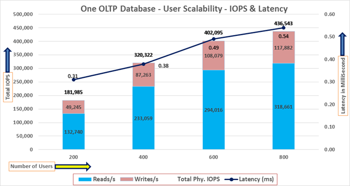
The chart below shows the Transaction Per Minutes (TPM) and System Utilization for the SOECDB Database while running the same above SwingBench Order Entry workload tests from 200 users to 800 users:
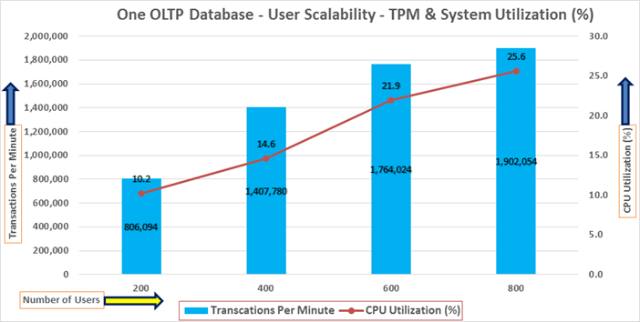
The AWR screenshot below was captured from one of the above test scenarios with 800 users running SwingBench Order Entry workload for sustained 24 hours across all four nodes.
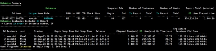
The following screenshot captured from the Oracle AWR report highlights the Physical Reads/Sec, Physical Writes/Sec and Transactions per Seconds for the Container SOECDB Database for the same above test. We captured about 428k IOPS (325k Reads/s and 103k Writes/s) with the 31k TPS (Transactions Per Seconds) while running this 24-hour sustained SwingBench Order Entry workload on one OLTP database with 800 users.
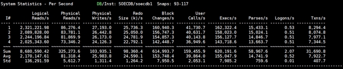
The following screenshot captured from the Oracle AWR report shows the SOECDB database “IO Profile” for the “Reads/s” and “Writes/s” requests for the entire 24-hour of the test. The Total Requests (Read and Write Per Second) were around “443k” with Total (MB) “Read+Write” Per Second was around “3605” MB/s for the SOECDB database while running the SwingBench Order Entry workload test on one database.
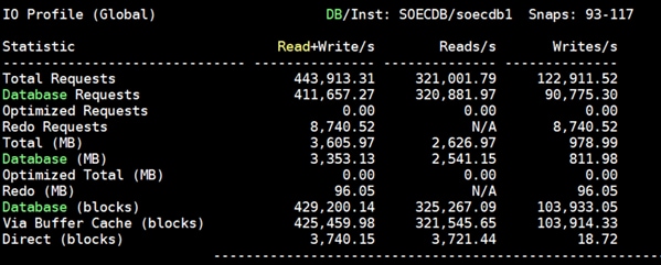
The following screenshot captured from the Oracle AWR report shows the “Top Timed Events” and average wait time for the SOECDB database for the entire duration of the test running with 800 users.
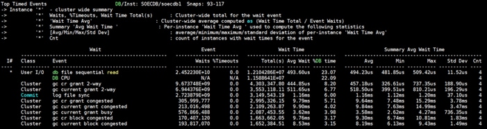
The following screenshot shows the NetApp Storage array Q S P S (qos statistics performance show) when one OLTP database was running the workload. The screenshot shows the average IOPS “450k” with the average throughput of “3600 MB/s” with the average storage latency around “0.7 millisecond.”
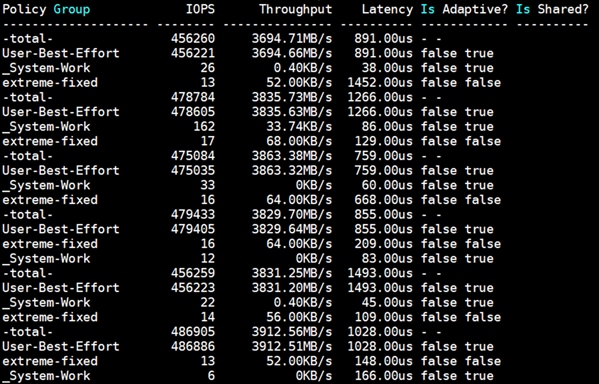
The storage cluster utilization during the above test was average around 45% which was an indication that storage hasn’t reached the threshold and could take more load by adding multiple databases.
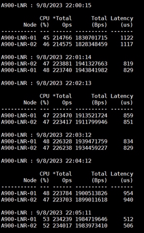
Also, for the entire 24-hour test, we observed the system performance (IOPS and Throughput) was consistent throughout and we did not observe any dips in performance while running one OLTP database stress test.
Multiple (Two) OLTP Databases Performance
For running multiple OLTP database workload, we have created two container database SOECDB and ENGCDB. For each container database, one pluggable database was configured as SOEPDB and ENGPDB as explained earlier. We ran the SwingBench SOE workload on both the databases at the same time with varying the total number of users on both the databases from 400 Users to 1200 Users. Each user scale iteration test was run for at least 3 hours and for each test scenario, we captured the Oracle AWR reports to check the overall system performance.
Table 16 lists the IOPS and System Utilization for each of the pluggable databases while running the workload from total of 400 users to 1200 users across all the four RAC nodes.
Table 16. IOPS and System Utilization for Pluggable Databases
| Users |
IOPS for SOECDB |
IOSP for ENGCDB |
Total IOPS |
System Utilization (%) |
| 178,553 |
170,676 |
349,229 |
16.8 |
|
| 600 |
256,347 |
246,399 |
502,746 |
25.3 |
| 800 |
294,534 |
292,094 |
586,628 |
31.2 |
| 1000 |
313,730 |
302,842 |
616,573 |
38.2 |
| 1200 |
325,373 |
308,121 |
633,494 |
42.9 |
The following chart shows the IOPS and System Utilization for both the container databases while running the SwingBench SOE workload on them at the same time. We observed both databases were linearly scaling the IOPS after increasing and scaling more users. We observed average 633k IOPS with overall system utilization around 43% when scaling maximum number of users on multiple OLTP database workload test. After increasing users beyond certain level, we observed more GC cluster events and overall similar IOPS around 630k.
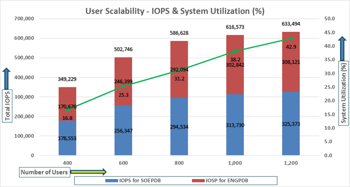
Table 17 lists the Transactions per Seconds (TPS) and Transactions per Minutes (TPM) for each of the pluggable databases while running the workload from total of 400 users to 1200 users across all the four RAC nodes.
Table 17. Transactions per Seconds and Transactions per Minutes
| Users |
TPS for SOECDB |
TPS for ENGCDB |
Total TPS |
Total TPM |
| 400 |
12,778 |
12,115 |
24,893 |
1,493,556 |
| 600 |
17,424 |
16,646 |
34,070 |
2,044,206 |
| 800 |
20,928 |
20,312 |
41,240 |
2,474,382 |
| 1000 |
22,294 |
20,861 |
43,155 |
2,589,306 |
| 1200 |
23,753 |
21,183 |
44,936 |
2,696,154 |
The following chart shows the Transactions per Seconds (TPS) for the same tests (above) on CDBDB Database for running the workload on both pluggable databases.
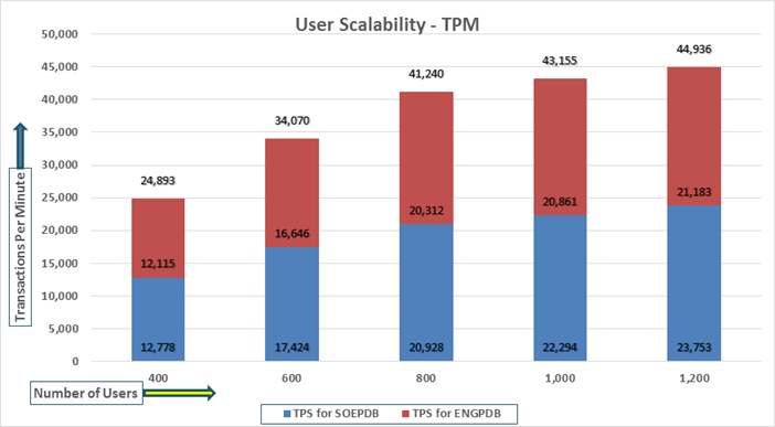
The following screenshot showcases the test start time for the first SOECDB database with 600 users running SwingBench Order Entry workload for sustained 24 hours across all four nodes as:
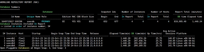
The following screenshot showcases the test start time for the second ENGCDB database with 600 users running SwingBench Order Entry workload for sustained 24 hours across all four nodes at the same time as:
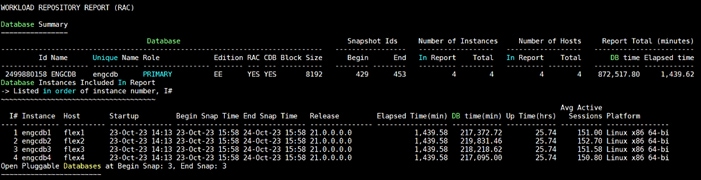
The following screenshot was captured from the Oracle AWR report, shows the “Physical Reads/Sec”, “Physical Writes/Sec” and “Transactions per Seconds” for the first Container Database SOECDB while running 600 users SOE workload for sustained 24 hour test. We captured about 364k IOPS (286k Reads/s and 78k Writes/s) with the 25k TPS (1,501,896 TPM) while running this workload test on two OLTP databases at the same time during this entire 24 hours sustained test.
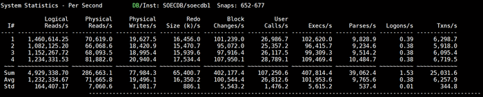
The following screenshot was captured from the second Container Database ENGCDB while running another 600 users on this second OLTP databases at the same time for sustained 24 hour test. We captured about 285k IOPS (212k Reads/s and 73k Writes/s) with the 19k TPS (1,142,628 TPM) while running the workload test on two databases at the same time during this 24 hours sustained test.
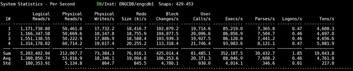
The following screenshot shows the SOECDB database “IO Profile” for the “Reads/s” and “Writes/s” requests for this multiple OLTP test running workload together for sustained 24-hour test. The Total Requests (Read and Write Per Second) were around “374k” with Total (MB) “Read+Write” Per Second was around “3021” MB/s for the first SOECDB database during this 24-hour test.
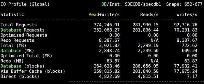
The following screenshot shows the ENGCDB database “IO Profile” for the “Reads/s” and “Writes/s” requests for this multiple OLTP test running workload together for sustained 24-hour test. The Total Requests (Read and Write Per Second) were around “293k” with Total (MB) “Read+Write” Per Second was around “2420” MB/s for the second ENGCDB database while running this workload for 24-hour.
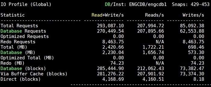
The following screenshot, “OS Statistics by Instance” while running the workload test for 24-hour on two OLTP databases at the same time. As shown below, the workload was equally spread across all the databases clusters while the average CPU utilization was around 37 % overall.
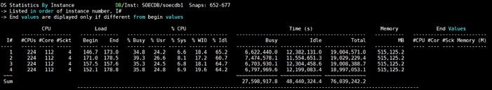
The following screenshot captured from the Oracle AWR report shows the “Top Timed Events” and average wait time for the first SOECDB database for the entire duration of the 24-hour workload test.
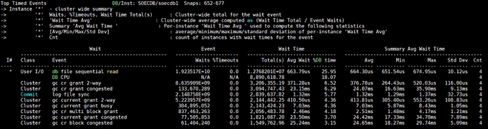
The following screenshot captured from the Oracle AWR report shows the “Top Timed Events” and average wait time for the second ENGCDB database for the entire duration of the 24-hour sustained workload test.
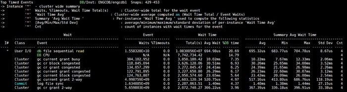
The following screenshot shows the NetApp Storage array “Q S P S (qos statistics performance show)” when multiple OLTP database was running the workload at the same time. The screenshot shows the average IOPS “650k” with the average throughput of “5100 MB/s” with the average latency around “0.5 millisecond”.
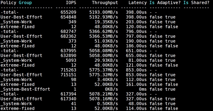
The following screenshot shows the NetApp Storage array cluster statistics performance when two OLTP database was running the workload at the same time. In the multiple OLTP database running workload together, we observed average storage cluster utilization about 63%.
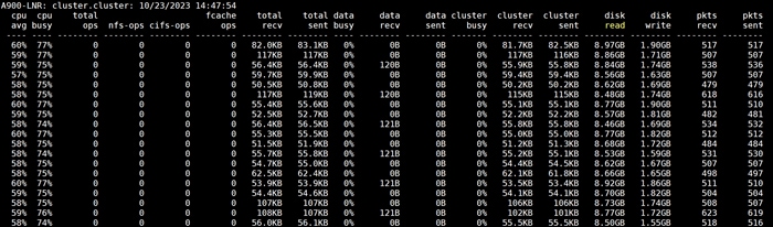
The following screenshot was captured from NetApp GUI during this 24 Hour multiple OLTP database running workload together test highlighting latency, IOPS and throughput for the entire 24-hour duration.
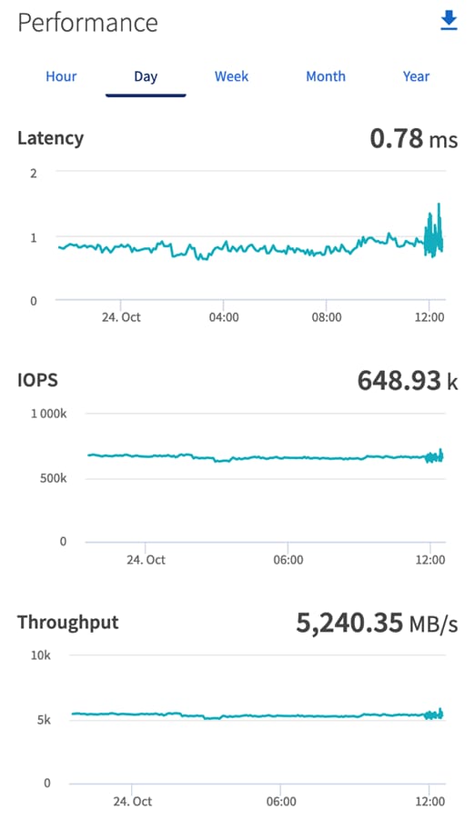
For the entire duration of the 24-hour test, we observed the system performance (IOPS, Latency and Throughput) was consistent throughout and we did not observe any dips in performance while running multiple OLTP database stress test.
DSS database workloads are generally sequential in nature, read intensive and exercise large IO size. DSS database workload runs a small number of users that typically exercise extremely complex queries that run for hours. For running oracle database multitenancy architecture, we configured one container database as SHCDB and into that container, we created one pluggable database as SHPDB as explained earlier.
We configured 4 TB of SHPDB pluggable database by loading Swingbench “SH” schema into Datafile Tablespace.
The following screenshot shows the database summary for the “SHCDB” database running for 24-hour duration. The container database “SHCDB” was also running with one pluggable databases “SHPDB” and the pluggable database was running the Swingbench SH workload for the entire 24-hour duration of the test across all four RAC nodes.
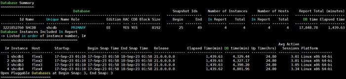
The following screenshot captured from Oracle AWR report shows the SHCDB database “IO Profile” for the “Reads/s” and “Writes/s” requests for the entire duration of the test. As the screenshots shows, the Total MB (Read and Write Per Second) were around “10,185 MB/s” for the SHPDB database while running this workload.
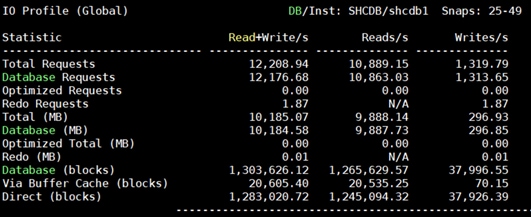
The following screenshot shows “Top Timed Events” for this container database SHCDB for the entire duration of the test while running SwingBench SH workload for 24-hours.
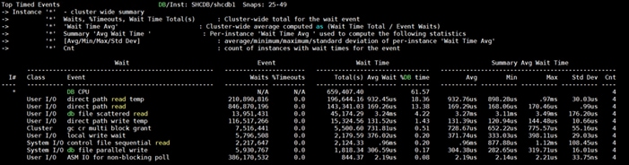
The following screenshot shows the NetApp storage array performance (Q S CH S (qos statistics characteristics show)) captured while running Swingbench SH workload on single DSS database. The screenshot shows the average throughput of “12,500 MB/s (12.5 GB/s)” while running the SwingBench SH workload on one DSS database.
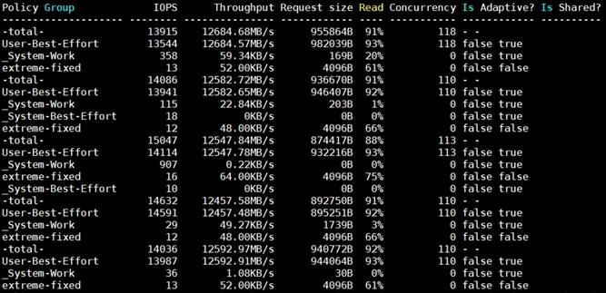
The following screenshot shows the NetApp Storage array “Q S P S (qos statistics performance show)” when one DSS database was running the workload. The screenshot shows the average throughput “12,500 MB/s” with average latency around “3 millisecond.”
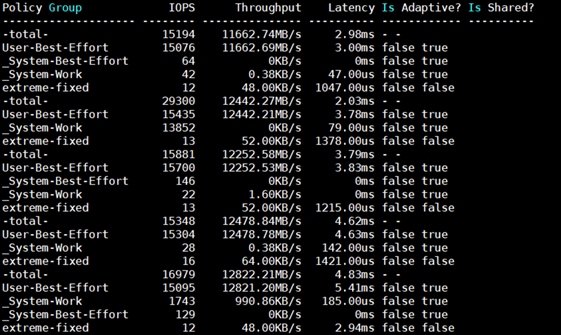
The following screenshot shows the NetApp Storage array cluster statistics performance while running the SwingBench SH workload test on one DSS database during this 24-hour. In this one DSS database use-case, we observed storage cluster utilization were around 25%. The database performance was consistent throughout the test, and we did not observe any dips in performance for entire period of 24-hour test.
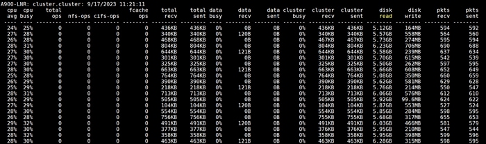
Multiple OLTP and DSS Databases Performance
In this mixed workload test, we ran Swingbench SOE workloads on both the OLTP (SOECDB + ENGCDB) databases and Swingbench SH workload on one DSS (SHCDB) Database at the same time and captured the overall system performance. We captured the system performance on small random queries presented via OLTP databases as well as large and sequential transactions submitted via DSS database workload as documented below.
The screenshot below shows the first OLTP database summary for the “SOECDB” database while running SwingBench Order Entry workload on first database for a 24-hour duration across all four nodes:
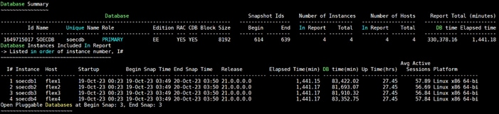
The following screenshot shows the test start time for the second OLTP database ENGCDB running SwingBench Order Entry workload for sustained 24 hours across all four nodes at the same time:
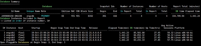
The following screenshot showcases the test start time for the third DSS database SHCDB running SwingBench Sales History workload for sustained 24 hours across all four nodes at the same time:
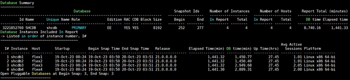
The following screenshot was captured from the Oracle AWR report, shows the “Physical Reads/Sec”, “Physical Writes/Sec” and “Transactions per Seconds” for the first OLTP Container Database SOECDB while running SOE workload for sustained 24-hour test. We captured about 222k IOPS (174k Reads/s and 48k Writes/s) with the 15k TPS (910,620 TPM) while running this test on first OLTP database during this 24-hour sustained mixed workload test:
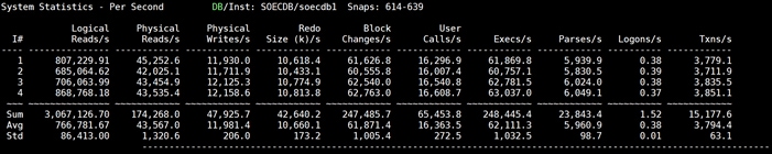
The following screenshot was captured from the second Container Database ENGCDB while running workload on this second OLTP databases at the same time for sustained 24-hour test. We captured about 210k IOPS (158k Reads/s and 53k Writes/s) with the 14k TPS (860,220 TPM) while running this test on second OLTP database during this 24-hour sustained mixed workload test:
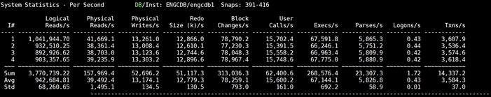
The following screenshot shows the first OLTP database SOECDB “IO Profile” for the “Reads/s” and “Writes/s” requests for the same above 24-hour mixed database workload tests. The Total Requests (Read and Write Per Second) were around “230k” with Total (MB) “Read+Write” Per Second was around “1858” MB/s for the first SOECDB database during this 24-hour test.
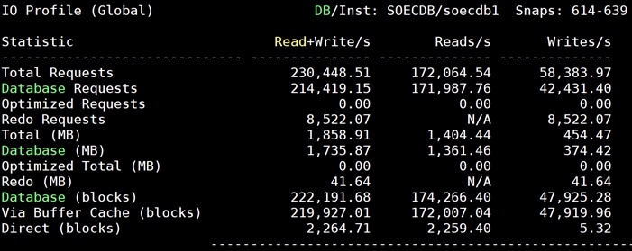
The following screenshot shows the ENGCDB database “IO Profile” for the “Reads/s” and “Writes/s” requests for the same above 24-hour mixed database workload tests. The Total Requests (Read and Write Per Second) were around “217k” with Total (MB) “Read+Write” Per Second was around “1778” MB/s for the second OLTP database ENGCDB during this 24-hour test.
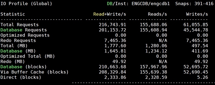
The following screenshot shows the SHCDB database “IO Profile” for the “Reads/s” and “Writes/s” requests for the same above 24-hour mixed database workload tests. The Total (MB) “Read+Write” Per Second was around “4343” MB/s for the third DSS database SHCDB during this 24-hour test.

The following screenshot captured from the Oracle AWR report shows the “Top Timed Events” and average wait time for the first OLTP database SOECDB for the entire duration of the 24-hour workload test.
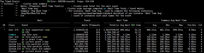
The following screenshot captured from the Oracle AWR report shows the “Top Timed Events” and average wait time for the second OLTP database ENGCDB for the entire duration of the 24-hour sustained workload test.
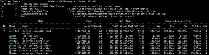
The following screenshot captured from the Oracle AWR report shows the “Top Timed Events” and average wait time for the third DSS database SHCDB for the entire duration of the 24-hour sustained workload test.
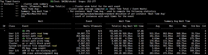
The following screenshot shows the NetApp Storage array “Q S P S (qos statistics performance show)” when mixed OLTP and DSS (SOECDB + ENGCDB + SHCDB) databases were running the workload at the same time. The screenshot shows the average IOPS “480k” with the average throughput of “6500 MB/s” with the average latency around “1.5 millisecond”.
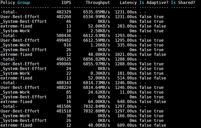
The following screenshot shows the NetApp Storage array cluster statistics performance when all three databases were running the workload at the same time. In the mixed OLTP and DSS (SOECDB + ENGCDB + SHCDB) databases running workload together, we observed average storage cluster utilization about 63%.
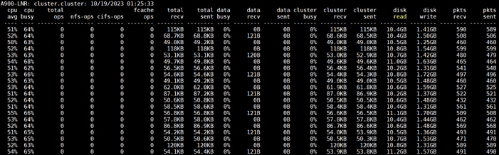
The following screenshot was captured from NetApp GUI during this 24 Hour multiple OLTP database running workload together test highlighting latency, IOPS and throughput for the entire 24-hour duration.
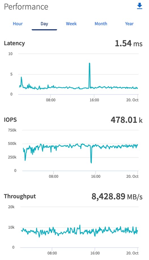
For the entire duration of this 24-hour mixed database workload tests, we observed the system performance (IOPS, Latency and Throughput) was consistent throughout and we did not observe any dips in performance while running this mixed OLTP and DSS database stress tests.
Resiliency and Failure Tests
This chapter contains the following:
· Test 1 – Cisco UCS-X Chassis IFM Links Failure
· Test 3 – Cisco Nexus Switch Failure
· Test 4 – Cisco MDS Switch Failure
· Test 5 – Storage Controller Links Failure
· Test 6 – Oracle RAC Server Node Failure
The goal of these tests was to ensure that the reference architecture withstands commonly occurring failures due to either unexpected crashes, hardware failures or human errors. We conducted many hardware (disconnect power), software (process kills) and OS specific failures that simulate the real world scenarios under stress conditions. In the destructive testing, we will also demonstrate the unique failover capabilities of Cisco UCS components used in this solution. Table 18 lists the test cases.
Table 18. Hardware Failover Tests
| Test Scenario |
Tests Performed |
| Test 1: UCS-X Chassis IFM Link/Links Failure |
Run the system on full Database workload. Disconnect one or two links from any of the Chassis 1 IFM or Chassis 2 IFM by pulling it out and reconnect it after 10-15 minutes. Capture the impact on overall database performance. |
| Test 2: One of the FI Failure |
Run the system on full Database workload. Power Off one of the Fabric Interconnects and check the network traffic on the other Fabric Interconnect and capture the impact on overall database performance. |
| Test 3: One of the Nexus Switch Failure |
Run the system on full Database workload. Power Off one of the Cisco Nexus switches and check the network and storage traffic on the other Nexus switch. Capture the impact on overall database performance. |
| Test 4: One of the MDS Switch Failure |
Run the system on full Database workload. Power Off one of the Cisco MDS switches and check the network and storage traffic on the other MDS switch. Capture the impact on overall database performance. |
| Test 5: Storage Controller Links Failure |
Run the system on full Database workload. Disconnect one link from each of the NetApp Storage Controllers by pulling it out and reconnect it after 10-15 minutes. Capture the impact on overall database performance. |
| Test 6: RAC Server Node Failure |
Run the system on full Database workload. Power Off one of the Linux Hosts and check the impact on database performance. |
The architecture below illustrates various failure scenario which can be occurred due to either unexpected crashes or hardware failures. The failure scenario 1 represents the Chassis IFM links failures while the scenario 2 represents the entire IFM module failure. Scenario 3 represents one of the Cisco UCS FI failure and similarly, scenario 4 and 5 represents one of the Cisco Nexus and MDS Switch failures. Scenario 6 represents the NetApp Storage Controllers link failures and Scenario 7 represents one of the Server Node Failures.
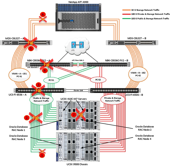
Note: All Hardware failover tests were conducted with all three databases (SOEPDB, ENGPDB and SHPDB) running Swingbench mixed workloads.
As previously explained, we configured to carry Oracle Public Network traffic on “VLAN 134” through FI – A and Oracle Private Interconnect Network traffic on “VLAN 10” through FI – B under normal operating conditions before the failover tests. We configured FC & NVMe/FC Storage Network Traffic access from both the Fabric Interconnects to MDS Switches on VSAN 151 and VSAN 152.
The screenshots below show a complete infrastructure details of MAC address and VLAN information for Cisco UCS FI – A and FI – B Switches before failover test. Log into FI – A and type “connect nxos” then type “show mac address-table” to see all the VLAN connection on the switch:
Similarly, log into FI – B and type “connect nxos” then type “show mac address-table” to see all the VLAN connection on the switch as follows:
Test 1 – Cisco UCS-X Chassis IFM Links Failure
We conducted the chassis IFM Links failure test on Cisco UCS Chassis 1 by disconnecting one of the server port link cables from the bottom chassis 1 as shown below:
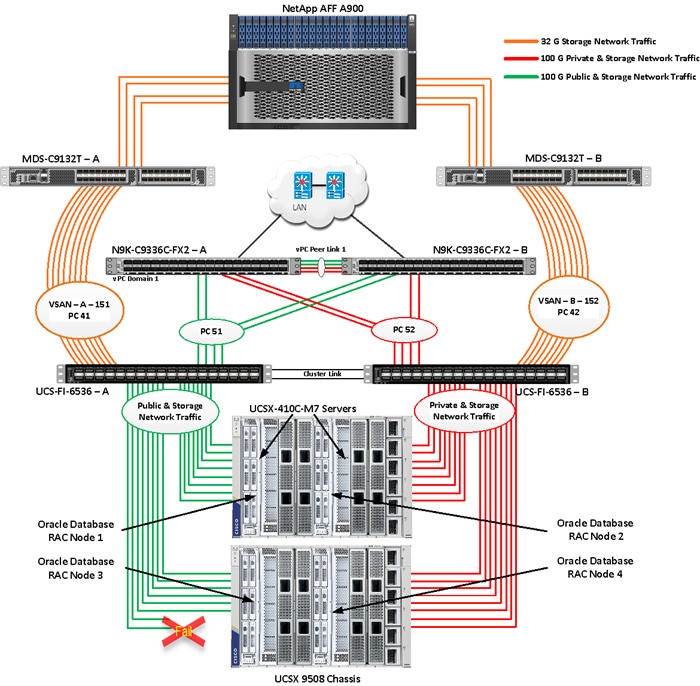
Unplug two server port cables from Chassis 1 and check all the VLAN and Storage traffic information on both Cisco UCS FIs, Database and NetApp Storage. We noticed no disruption in any of the network and storage traffic and the database kept running under normal working conditions even after multiple IFM links failed from Chassis because of the Cisco UCS Port-Channel Feature.
We also conducted the IFM module test and removed the entire IFM module from one of the chassis as shown below:
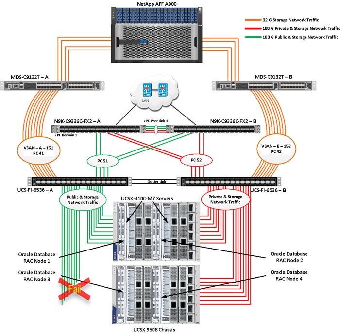
The screenshot below shows the database workload performance from the storage array when the chassis IFM module links failed:
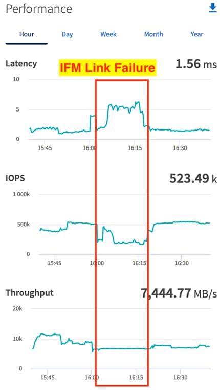
We noticed no disruption in any of the network and storage traffic and the database kept running under normal working conditions even after multiple IFM links failed. We kept the chassis IFM links down for 15-20 minutes and then reconnected those failed links and observed no disruption in network traffic and database operation.
We conducted a hardware failure test on FI-A by disconnecting the power cable to the fabric interconnect switch.
The figure below illustrates how during FI-A switch failure, the respective nodes (flex1 and flex2) on chassis 1 and nodes (flex3 and flex4) on chassis 2 will re-route the VLAN (134 - Management Network) traffic through the healthy Fabric Interconnect Switch FI-B. However, storage traffic VSANs from FI – A switch were not able to failover to FI – B because of those storage interfaces traffic is not capable of failing over to another switch.
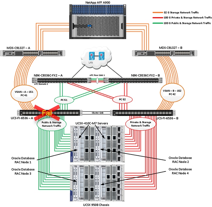
Log into FI – B and type “connect nxos” then type “show mac address-table” to see all VLAN connection on FI – B.
In the screenshot below, we noticed when the FI-A failed, all the MAC addresses of the redundant vNICs kept their VLANs network traffic going through FI-B. We observed that MAC addresses of public network vNICs (each server having 1 vNIC for VLAN 134) were failed over to other FI and database network traffic kept running under normal conditions even after failure of one of the FI.
However, Storage Network Traffic for VSAN 151 were not able to fail-over to another FI Switch and thus we lost half of the storage traffic connectivity from the Oracle RAC Databases to Storage Array. The screenshot below shows the NetApp Storage Array performance of the mixed workloads on all the databases while one of the FI failed.
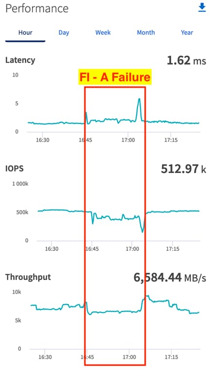
We also monitored and captured databases and its performance during this FI failure test through database alert log files and AWR reports. When we disconnected the power from FI – A, it caused a momentary impact on performance on the overall total IOPS, latency on OLTP as well as throughput on the DSS database for a few seconds but noticed that we did not see any interruption in any Private Server to Server Oracle RAC Interconnect Network, Management Public Network and Storage network traffic on IO Service Requests to the storage. We observed the database workload kept running under normal conditions throughout duration of FI failure.
We noticed this behavior because each server node can failover vNICs from one fabric interconnect switch to another fabric interconnect switch but there is no vHBA storage traffic failover from one fabric interconnect switch to another fabric interconnect switch. Therefore, in case of any one fabric interconnect failure, we would lose half of the number of vHBAs or storage paths and consequently we observe momentary databases performance impact for few seconds on the overall system as shown in the graph (above).
After plugging back power cable to FI-A Switch, the respective nodes (flex1and flex2) on chassis 1 and nodes (flex3 and flex4) on chassis 2 will route back the MAC addresses and its VLAN public network and storage network traffic to FI-A. After FI – A arrives in normal operating state, all the nodes to storage connectivity, the operating system level multipath configuration will bring back all the path back to active and database performance will resume to peak performance
Test 3 – Cisco Nexus Switch Failure
We conducted a hardware failure test on Cisco Nexus Switch-A by disconnecting the power cable to the Cisco Nexus Switch and checking the public, private and storage network traffic on Cisco Nexus Switch-B and the overall system as shown below:
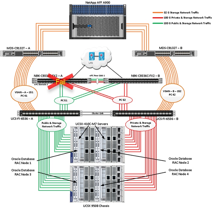
The screenshot below shows the vpc summary on Cisco Nexus Switch B while Cisco Nexus A was down.
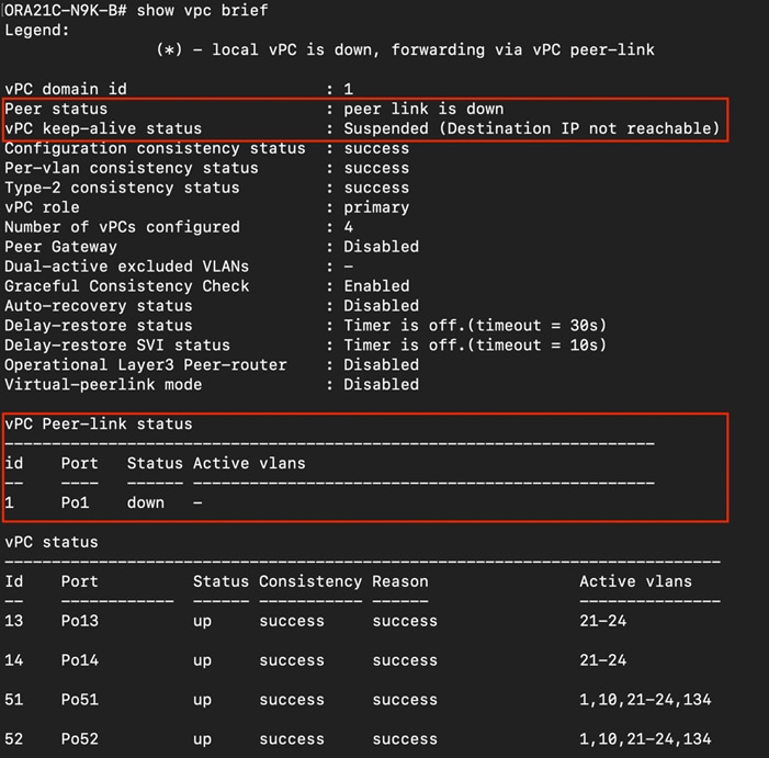
When we disconnected the power from Cisco Nexus-A Switch, it caused no impact on database performance of the overall total IOPS, latency on OLTP as well as throughput of the DSS database and noticed no interruption in the overall Private Server to Server Oracle RAC Interconnect Network, Management Public Network, and storage network traffic on I/O Service Requests to the storage.
Such as FI failure tests, we observed no impact overall on all three databases performance and all the VLAN network traffic were going through other active Cisco Nexus switch B and databases workload kept running under normal conditions throughout the duration of Nexus failure. After plugging back the power cable back into Cisco Nexus-A Switch, Nexus Switch returns to normal operating state and database performance continue peak performance.
Test 4 – Cisco MDS Switch Failure
We conducted a hardware failure test on Cisco MDS Switch-A by disconnecting the power cable to the MDS Switch and checking the public, private and storage network traffic on Cisco MDS Switch-B and the overall system as shown below:
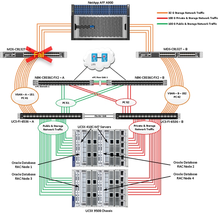
Similar to FI failure tests, we observed some impact on all three databases performance as we lost half of the VSAN (VSAN-A 151) traffic. While VSAN-A (151) stays locally into the switch and only carry storage traffic through the MDS switch A, VSAN-A doesn’t failover to MDS Switch B therefore we reduced server to storage connectivity into half during MDS Switch A failure. However, failure in MDS Switch did not cause any disruption to Private and Public Network Traffic.
We also recorded performance of the databases from the storage array “Q S P S “where we observed momentary impact on performance on overall IOPS, latency on OLTP as well as throughput on DSS database for few seconds.
After plugging back power cable to MDS Switch A, the operating system level multipath configuration will bring back all the path back to active and database performance will resume to peak performance.
Test 5 – Storage Controller Links Failure
We performed storage controller link failure test by disconnecting two of the FC 32G links from the NetApp Array from one of the storage controller as shown below:
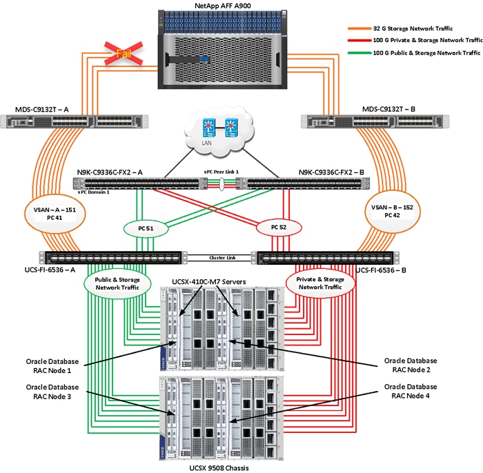
Similar to FI and MDS failure tests, storage link failure did not cause any disruption to Private, Public and Storage Network Traffic. After plugging back FC links to storage controller, MDS Switch and Storage array links comes back online, and the operating system level multipath configuration will bring back all the path back to active and database performance will resume to peak performance.
Test 6 – Oracle RAC Server Node Failure
In this test, we started the SwingBench workload test run on all 4 RAC nodes, and then during run, we powered down one node from the RAC cluster to check the overall system performance. We didn’t observe any performance impact on overall database IOPS, latency and throughput after losing one node from the system.
We completed an additional failure scenario and validated that there is no single point of failure in this reference design.
Summary
The Cisco Unified Computing System (Cisco UCS) is a next-generation data center platform that unites computing, network, storage access, and virtualization into a single cohesive system. Cisco UCS is an ideal platform for the architecture of mission critical database workloads such as Oracle RAC. The combination of Cisco UCS, NetApp and Oracle Real Application Cluster Database architecture can accelerate your IT transformation by enabling faster deployments, greater flexibility of choice, efficiency, high availability, and lower risk. The FlexPod Datacenter solution is a validated approach for deploying Cisco and NetApp technologies and products to build shared private and public cloud infrastructure.
If you’re interested in understanding the FlexPod design and deployment details, including the configuration of various elements of design and associated best practices, refer to Cisco Validated Designs for FlexPod, here: https://www.cisco.com/c/en/us/solutions/design-zone/data-center-design-guides/flexpod-design-guides.html.
The FlexPod Datacenter solution with Cisco UCS X-Series and NetApp AFF Storage using NetApp ONTAP offers the following key customer benefits:
· Simplified cloud-based management of solution components.
· Hybrid-cloud-ready, policy-driven modular design.
· Highly available and scalable platform with flexible architecture that supports various deployment models.
· Cooperative support model and Cisco Solution Support.
· Easy to deploy, consume, and manage architecture, which saves time and resources required to research, procure, and integrate off-the-shelf components.
· Support for component monitoring, solution automation and orchestration, and workload optimization.
Hardikkumar Vyas, Technical Marketing Engineer, CSPG UCS Product Management and Data Center Solutions Engineering Group, Cisco Systems, Inc.
Hardikkumar Vyas is a Solution Architect in Cisco System’s Cloud and Compute Engineering Group for configuring, implementing, and validating infrastructure best practices for highly available Oracle RAC databases solutions on Cisco UCS Servers, Cisco Nexus Products, and various Storage Technologies. Hardikkumar Vyas holds a master’s degree in electrical engineering and has over 10 years of experience working with Oracle RAC Databases and associated applications. Hardikkumar Vyas’s focus is developing database solutions on different platforms, perform benchmarks, prepare reference architectures, and write technical documents for Oracle RAC Databases on Cisco UCS Platforms.
Tushar Patel, Distinguished Technical Marketing Engineer , CSPG UCS Product Management and Data Center Solutions Engineering Group, Cisco Systems, Inc.
Tushar Patel is a Distinguished Technical Marketing Engineer in Cisco System’s CSPG UCS Product Management and Data Center Solutions Engineering Group and a specialist in Flash Storage technologies and Oracle RAC RDBMS. Tushar has over 27 years of experience in Flash Storage architecture, Database architecture, design, and performance. Tushar also has strong background in Intel X86 architecture, hyper converged systems, Storage technologies and Virtualization. He has worked with large number of enterprise customers, to evaluate, and deploy mission critical database solutions. Tushar has presented to both internal and external audiences at various conferences and customer events.
For their support and contribution to the design, validation, and creation of this Cisco Validated Design, the authors would like to thank:
· Bobby Oommen, Sr. Manager FlexPod Solutions, NetApp
This appendix contains the following:
· Compute
· Network
· Storage
· Cisco MDS Switch Configuration
· Cisco Nexus Switch Configuration
· Multipath Configuration “/etc/multipath.conf”
· Configure “/etc/udev/rules.d/71-nvme-iopolicy-netapp-ONTAP.rules”
· Configure “/etc/udev/rules.d/80-nvme.rules”
· Configure “oracle-database-preinstall-21c.conf”
Cisco Intersight: https://www.intersight.com
Cisco Intersight Managed Mode: https://www.cisco.com/c/en/us/td/docs/unified_computing/Intersight/b_Intersight_Managed_Mode_Configuration_Guide.html
Cisco Unified Computing System: http://www.cisco.com/en/US/products/ps10265/index.html
Cisco UCS 6536 Fabric Interconnects: https://www.cisco.com/c/en/us/products/collateral/servers-unified-computing/ucs6536-fabric-interconnect-ds.html
Cisco Nexus 9000 Series Switches: http://www.cisco.com/c/en/us/products/switches/nexus-9000-series-switches/index.html
Cisco MDS 9132T Switches: https://www.cisco.com/c/en/us/products/collateral/storage-networking/mds-9100-series-multilayer-fabric-switches/datasheet-c78-739613.html
NetApp ONTAP: https://docs.netapp.com/ontap-9/index.jsp
NetApp Active IQ Unified Manager: https://community.netapp.com/t5/Tech-ONTAP-Blogs/Introducing-NetApp-Active-IQ-Unified-Manager-9-11/ba-p/435519
ONTAP Storage Connector for Cisco Intersight: https://www.netapp.com/pdf.html?item=/media/25001-tr-4883.pdf
ONTAP tools for VMware vSphere: https://docs.netapp.com/us-en/ontap-tools-vmware-vsphere/index.html
NetApp SnapCenter: https://docs.netapp.com/us-en/snapcenter/index.html
Cisco UCS Hardware Compatibility Matrix: https://ucshcltool.cloudapps.cisco.com/public/
NetApp Interoperability Matrix Tool: http://support.netapp.com/matrix/
Cisco MDS Switch Configuration
MDS-A-ORA21C-B15# show running-config
!Command: show running-config
!Running configuration last done at: Mon Oct 16 05:30:04 2023
!Time: Wed Oct 18 00:32:42 2023
version 9.3(2)
power redundancy-mode redundant
feature fport-channel-trunk
feature telnet
logging level zone 3
role name default-role
description This is a system defined role and applies to all users.
rule 5 permit show feature environment
rule 4 permit show feature hardware
rule 3 permit show feature module
rule 2 permit show feature snmp
rule 1 permit show feature system
no password strength-check
username admin password 5 $5$2y/LoDYD$C.F07a9IeeaA7AozbK.74gFTNjGSQcumaTtiGBSoo4D role network-admin
username svc-nxcloud password 5 ! role network-admin
username svc-nxcloud passphrase lifetime 99999 warntime 14 gracetime 3
ip domain-lookup
ip host MDS-A-ORA21C-B15 10.29.134.47
ntp server 72.163.32.44
vsan database
vsan 151 name "VSAN-FI-A"
device-alias database
device-alias name FLEX1-FC-HBA0 pwwn 20:00:00:25:b5:ab:91:90
device-alias name FLEX2-FC-HBA0 pwwn 20:00:00:25:b5:ab:91:96
device-alias name FLEX3-FC-HBA0 pwwn 20:00:00:25:b5:ab:91:c0
device-alias name FLEX4-FC-HBA0 pwwn 20:00:00:25:b5:ab:91:a2
device-alias name FLEX1-NVMe-HBA2 pwwn 20:00:00:25:b5:ab:91:92
device-alias name FLEX1-NVMe-HBA4 pwwn 20:00:00:25:b5:ab:91:94
device-alias name FLEX1-NVMe-HBA6 pwwn 20:00:00:25:b5:ab:91:d2
device-alias name FLEX1-NVMe-HBA8 pwwn 20:00:00:25:b5:ab:91:de
device-alias name FLEX2-NVMe-HBA2 pwwn 20:00:00:25:b5:ab:91:98
device-alias name FLEX2-NVMe-HBA4 pwwn 20:00:00:25:b5:ab:91:9a
device-alias name FLEX2-NVMe-HBA6 pwwn 20:00:00:25:b5:ab:91:d3
device-alias name FLEX2-NVMe-HBA8 pwwn 20:00:00:25:b5:ab:91:df
device-alias name FLEX3-NVMe-HBA2 pwwn 20:00:00:25:b5:ab:91:c2
device-alias name FLEX3-NVMe-HBA4 pwwn 20:00:00:25:b5:ab:91:c4
device-alias name FLEX3-NVMe-HBA6 pwwn 20:00:00:25:b5:ab:91:d7
device-alias name FLEX3-NVMe-HBA8 pwwn 20:00:00:25:b5:ab:91:e3
device-alias name FLEX4-NVMe-HBA2 pwwn 20:00:00:25:b5:ab:91:a4
device-alias name FLEX4-NVMe-HBA4 pwwn 20:00:00:25:b5:ab:91:a6
device-alias name FLEX4-NVMe-HBA6 pwwn 20:00:00:25:b5:ab:91:d4
device-alias name FLEX4-NVMe-HBA8 pwwn 20:00:00:25:b5:ab:91:e0
device-alias name ORA21C-NVME-LIF-01-9a pwwn 20:27:d0:39:ea:4f:4b:49
device-alias name ORA21C-NVME-LIF-01-9c pwwn 20:17:d0:39:ea:4f:4b:49
device-alias name ORA21C-NVME-LIF-02-9a pwwn 20:31:d0:39:ea:4f:4b:49
device-alias name ORA21C-NVME-LIF-02-9c pwwn 20:19:d0:39:ea:4f:4b:49
device-alias name Infra-SVM-FC-LIF-01-9a pwwn 20:0c:d0:39:ea:4f:4b:49
device-alias name Infra-SVM-FC-LIF-02-9a pwwn 20:0e:d0:39:ea:4f:4b:49
device-alias commit
system default zone distribute full
zone smart-zoning enable vsan 151
zoneset distribute full vsan 151
!Active Zone Database Section for vsan 151
zone name FLEX-1-Boot-A vsan 151
member device-alias FLEX1-FC-HBA0 init
member device-alias Infra-SVM-FC-LIF-01-9a target
member device-alias Infra-SVM-FC-LIF-02-9a target
zone name FLEX-2-Boot-A vsan 151
member device-alias FLEX2-FC-HBA0 init
member device-alias Infra-SVM-FC-LIF-01-9a target
member device-alias Infra-SVM-FC-LIF-02-9a target
zone name FLEX-3-Boot-A vsan 151
member device-alias FLEX3-FC-HBA0 init
member device-alias Infra-SVM-FC-LIF-01-9a target
member device-alias Infra-SVM-FC-LIF-02-9a target
zone name FLEX-4-Boot-A vsan 151
member device-alias FLEX4-FC-HBA0 init
member device-alias Infra-SVM-FC-LIF-01-9a target
member device-alias Infra-SVM-FC-LIF-02-9a target
zone name FLEX-1-NVME-A1 vsan 151
member device-alias FLEX1-NVMe-HBA2 init
member device-alias FLEX1-NVMe-HBA4 init
member device-alias FLEX1-NVMe-HBA6 init
member device-alias FLEX1-NVMe-HBA8 init
member device-alias ORA21C-NVME-LIF-01-9c target
member device-alias ORA21C-NVME-LIF-02-9c target
member device-alias ORA21C-NVME-LIF-01-9a target
member device-alias ORA21C-NVME-LIF-02-9a target
zone name FLEX-2-NVME-A1 vsan 151
member device-alias FLEX2-NVMe-HBA2 init
member device-alias FLEX2-NVMe-HBA4 init
member device-alias FLEX2-NVMe-HBA6 init
member device-alias FLEX2-NVMe-HBA8 init
member device-alias ORA21C-NVME-LIF-01-9c target
member device-alias ORA21C-NVME-LIF-02-9c target
member device-alias ORA21C-NVME-LIF-01-9a target
member device-alias ORA21C-NVME-LIF-02-9a target
zone name FLEX-3-NVME-A1 vsan 151
member device-alias FLEX3-NVMe-HBA2 init
member device-alias FLEX3-NVMe-HBA4 init
member device-alias FLEX3-NVMe-HBA6 init
member device-alias FLEX3-NVMe-HBA8 init
member device-alias ORA21C-NVME-LIF-01-9c target
member device-alias ORA21C-NVME-LIF-02-9c target
member device-alias ORA21C-NVME-LIF-01-9a target
member device-alias ORA21C-NVME-LIF-02-9a target
zone name FLEX-4-NVME-A1 vsan 151
member device-alias FLEX4-NVMe-HBA2 init
member device-alias FLEX4-NVMe-HBA4 init
member device-alias FLEX4-NVMe-HBA6 init
member device-alias FLEX4-NVMe-HBA8 init
member device-alias ORA21C-NVME-LIF-01-9c target
member device-alias ORA21C-NVME-LIF-02-9c target
member device-alias ORA21C-NVME-LIF-01-9a target
member device-alias ORA21C-NVME-LIF-02-9a target
zoneset name FLEX-A vsan 151
member FLEX-1-Boot-A
member FLEX-2-Boot-A
member FLEX-3-Boot-A
member FLEX-4-Boot-A
member FLEX-1-NVME-A1
member FLEX-2-NVME-A1
member FLEX-3-NVME-A1
member FLEX-4-NVME-A1
zoneset activate name FLEX-A vsan 151
interface mgmt0
ip address 10.29.134.47 255.255.255.0
interface port-channel41
switchport trunk allowed vsan 151
switchport description Port-Channel-FI-A-MDS-A
switchport rate-mode dedicated
switchport trunk mode off
vsan database
vsan 151 interface port-channel41
vsan 151 interface fc1/9
vsan 151 interface fc1/10
vsan 151 interface fc1/11
vsan 151 interface fc1/12
vsan 151 interface fc1/13
vsan 151 interface fc1/14
vsan 151 interface fc1/15
vsan 151 interface fc1/16
vsan 151 interface fc1/17
vsan 151 interface fc1/18
vsan 151 interface fc1/19
vsan 151 interface fc1/20
vsan 151 interface fc1/21
vsan 151 interface fc1/22
vsan 151 interface fc1/23
vsan 151 interface fc1/24
vsan 151 interface fc1/25
vsan 151 interface fc1/26
vsan 151 interface fc1/27
vsan 151 interface fc1/28
vsan 151 interface fc1/29
vsan 151 interface fc1/30
vsan 151 interface fc1/31
vsan 151 interface fc1/32
switchname MDS-A-ORA21C-B15
cli alias name autozone source sys/autozone.py
line console
line vty
boot kickstart bootflash:/m9100-s6ek9-kickstart-mz.9.3.2.bin
boot system bootflash:/m9100-s6ek9-mz.9.3.2.bin
interface fc1/1
switchport speed auto
interface fc1/2
switchport speed auto
interface fc1/3
switchport speed auto
interface fc1/4
switchport speed auto
interface fc1/5
switchport speed auto
interface fc1/6
switchport speed auto
interface fc1/7
switchport speed auto
interface fc1/8
switchport speed auto
interface fc1/9
switchport speed auto
interface fc1/10
switchport speed auto
interface fc1/11
switchport speed auto
interface fc1/12
switchport speed auto
interface fc1/13
switchport speed auto
interface fc1/14
switchport speed auto
interface fc1/15
switchport speed auto
interface fc1/16
switchport speed auto
interface fc1/17
switchport speed auto
interface fc1/18
switchport speed auto
interface fc1/19
switchport speed auto
interface fc1/20
switchport speed auto
interface fc1/21
switchport speed auto
interface fc1/22
switchport speed auto
interface fc1/23
switchport speed auto
interface fc1/24
switchport speed auto
interface fc1/25
switchport speed auto
interface fc1/26
switchport speed auto
interface fc1/27
switchport speed auto
interface fc1/28
switchport speed auto
interface fc1/29
switchport speed auto
interface fc1/30
switchport speed auto
interface fc1/31
switchport speed auto
interface fc1/32
switchport speed auto
interface fc1/1
switchport description ORA21C-FI-A-1/35/1
switchport trunk mode off
port-license acquire
channel-group 41 force
no shutdown
interface fc1/2
switchport description ORA21C-FI-A-1/35/2
switchport trunk mode off
port-license acquire
channel-group 41 force
no shutdown
interface fc1/3
switchport description ORA21C-FI-A-1/35/3
switchport trunk mode off
port-license acquire
channel-group 41 force
no shutdown
interface fc1/4
switchport description ORA21C-FI-A-1/35/4
switchport trunk mode off
port-license acquire
channel-group 41 force
no shutdown
interface fc1/5
switchport description ORA21C-FI-A-1/36/1
switchport trunk mode off
port-license acquire
channel-group 41 force
no shutdown
interface fc1/6
switchport description ORA21C-FI-A-1/36/2
switchport trunk mode off
port-license acquire
channel-group 41 force
no shutdown
interface fc1/7
switchport description ORA21C-FI-A-1/36/3
switchport trunk mode off
port-license acquire
channel-group 41 force
no shutdown
interface fc1/8
switchport description ORA21C-FI-A-1/36/4
switchport trunk mode off
port-license acquire
channel-group 41 force
no shutdown
interface fc1/17
switchport trunk allowed vsan 151
switchport description A900-01-NVMe-FC-LIF-9a
switchport trunk mode off
port-license acquire
no shutdown
interface fc1/18
switchport trunk allowed vsan 151
switchport description A900-02-NVMe-FC-LIF-9a
switchport trunk mode off
port-license acquire
no shutdown
interface fc1/19
switchport trunk allowed vsan 151
switchport description A900-01-NVMe-FC-LIF-9c
switchport trunk mode off
port-license acquire
no shutdown
interface fc1/20
switchport trunk allowed vsan 151
switchport description A900-02-NVMe-FC-LIF-9c
switchport trunk mode off
port-license acquire
no shutdown
ip default-gateway 10.29.134.1
Cisco Nexus Switch Configuration
ORA21C-N9K-A# show running-config
!Command: show running-config
!Running configuration last done at: Mon Apr 10 22:04:13 2023
!Time: Fri May 2 07:51:54 2023
version 9.2(3) Bios:version 05.33
switchname ORA21C-N9K-A
policy-map type network-qos jumbo
class type network-qos class-default
mtu 9216
vdc ORA21C-N9K-A id 1
limit-resource vlan minimum 16 maximum 4094
limit-resource vrf minimum 2 maximum 4096
limit-resource port-channel minimum 0 maximum 511
limit-resource u4route-mem minimum 248 maximum 248
limit-resource u6route-mem minimum 96 maximum 96
limit-resource m4route-mem minimum 58 maximum 58
limit-resource M7route-mem minimum 8 maximum 8
cfs eth distribute
feature interface-vlan
feature hsrp
feature lacp
feature vpc
feature lldp
no password strength-check
username admin password 5 $5$QyO36Ye4$xKHjJmPA/zgfNSpblJPcbu7GgNA0GweKS/xOzUjCcK4 role network-admin
ip domain-lookup
system default switchport
system qos
service-policy type network-qos jumbo
copp profile strict
snmp-server user admin network-admin auth md5 0xab8f5da7966d49de676779a717fb6b92 priv 0xab8f5da7966d49de676779a717fb6b92 localizedkey
rmon event 1 description FATAL(1) owner PMON@FATAL
rmon event 2 description CRITICAL(2) owner PMON@CRITICAL
rmon event 3 description ERROR(3) owner PMON@ERROR
rmon event 4 description WARNING(4) owner PMON@WARNING
rmon event 5 description INFORMATION(5) owner PMON@INFO
ntp server 72.163.32.44 use-vrf default
vlan 1,10,21-24,134
vlan 10
name Oracle_RAC_Private_Traffic
vlan 134
name Oracle_RAC_Public_Traffic
spanning-tree port type edge bpduguard default
spanning-tree port type network default
vrf context management
ip route 0.0.0.0/0 10.29.134.1
vpc domain 1
peer-keepalive destination 10.29.134.44 source 10.29.134.43
interface Vlan1
interface Vlan134
no shutdown
interface port-channel1
description VPC peer-link
switchport mode trunk
switchport trunk allowed vlan 1,10,134
spanning-tree port type network
vpc peer-link
interface port-channel51
description connect to ORA21C-FI-A
switchport mode trunk
switchport trunk allowed vlan 1,10,134
spanning-tree port type edge trunk
mtu 9216
vpc 51
interface port-channel52
description connect to ORA21C-FI-B
switchport mode trunk
switchport trunk allowed vlan 1,10,134
spanning-tree port type edge trunk
mtu 9216
vpc 52
interface Ethernet1/1
description Peer link connected to ORA21C-N9K-B-Eth1/1
switchport mode trunk
switchport trunk allowed vlan 1,10,134
channel-group 1 mode active
interface Ethernet1/2
description Peer link connected to ORA21C-N9K-B-Eth1/2
switchport mode trunk
switchport trunk allowed vlan 1,10,134
channel-group 1 mode active
interface Ethernet1/3
description Peer link connected to ORA21C-N9K-B-Eth1/3
switchport mode trunk
switchport trunk allowed vlan 1,10,134
channel-group 1 mode active
interface Ethernet1/4
description Peer link connected to ORA21C-N9K-B-Eth1/4
switchport mode trunk
switchport trunk allowed vlan 1,10,134
channel-group 1 mode active
interface Ethernet1/5
interface Ethernet1/6
interface Ethernet1/7
interface Ethernet1/8
interface Ethernet1/9
description Fabric-Interconnect-A-27
switchport mode trunk
switchport trunk allowed vlan 1,10,134
spanning-tree port type edge trunk
mtu 9216
channel-group 51 mode active
interface Ethernet1/10
description Fabric-Interconnect-A-28
switchport mode trunk
switchport trunk allowed vlan 1,10,134
spanning-tree port type edge trunk
mtu 9216
channel-group 51 mode active
interface Ethernet1/11
description Fabric-Interconnect-B-27
switchport mode trunk
switchport trunk allowed vlan 1,10,134
spanning-tree port type edge trunk
mtu 9216
channel-group 52 mode active
interface Ethernet1/12
description Fabric-Interconnect-B-28
switchport mode trunk
switchport trunk allowed vlan 1,10,134
spanning-tree port type edge trunk
mtu 9216
channel-group 52 mode active
interface Ethernet1/13
interface Ethernet1/14
interface Ethernet1/15
interface Ethernet1/16
interface Ethernet1/17
interface Ethernet1/18
interface Ethernet1/19
interface Ethernet1/20
interface Ethernet1/21
interface Ethernet1/22
interface Ethernet1/23
interface Ethernet1/24
interface Ethernet1/25
interface Ethernet1/26
interface Ethernet1/27
interface Ethernet1/28
interface Ethernet1/29
description To-Management-Uplink-Switch
switchport access vlan 134
speed 1000
interface Ethernet1/30
interface Ethernet1/31
interface Ethernet1/32
interface Ethernet1/33
interface Ethernet1/34
interface Ethernet1/35
interface Ethernet1/36
interface mgmt0
vrf member management
ip address 10.29.134.43/24
line console
line vty
boot nxos bootflash:/nxos.9.2.3.bin
no system default switchport shutdown
Multipath Configuration “/etc/multipath.conf”
[root@flex1 ~]# cat /etc/multipath.conf
defaults {
find_multipaths yes
user_friendly_names yes
enable_foreign NONE
}
multipaths {
multipath {
wwid 3600a09803831377a522b55652f36796a
alias Flex1_OS
}
}
Configure “/etc/udev/rules.d/71-nvme-iopolicy-netapp-ONTAP.rules”
[root@flex1 ~]# cat /etc/udev/rules.d/71-nvme-iopolicy-netapp-ONTAP.rules
### Enable round-robin for NetApp ONTAP
ACTION=="add", SUBSYSTEM=="nvme-subsystem", ATTR{model}=="NetApp ONTAP Controller", ATTR{iopolicy}="round-robin"
Configure “/etc/udev/rules.d/80-nvme.rules”
[root@flex1 ~]# cat /etc/udev/rules.d/80-nvme.rules
KERNEL=="nvme[0-999]*n[0-999]*", ENV{DEVTYPE}=="disk", ENV{ID_WWN}=="uuid.ad49c5c8-59e8-4d48-a005-a263aaf9b553", SYMLINK+="fiovol111", GROUP:="root", OWNER:="root", MODE:="660"
KERNEL=="nvme[0-999]*n[0-999]*", ENV{DEVTYPE}=="disk", ENV{ID_WWN}=="uuid.699742b9-0c3b-468b-bcac-e7decba87b47", SYMLINK+="fiovol112", GROUP:="root", OWNER:="root", MODE:="660"
KERNEL=="nvme[0-999]*n[0-999]*", ENV{DEVTYPE}=="disk", ENV{ID_WWN}=="uuid.4874fad2-76c4-44e5-8aa2-e2b4f1a34c2b", SYMLINK+="fiovol113", GROUP:="root", OWNER:="root", MODE:="660"
KERNEL=="nvme[0-999]*n[0-999]*", ENV{DEVTYPE}=="disk", ENV{ID_WWN}=="uuid.f23e8852-4fd2-4063-91fd-f503ff4e00f7", SYMLINK+="fiovol114", GROUP:="root", OWNER:="root", MODE:="660"
KERNEL=="nvme[0-999]*n[0-999]*", ENV{DEVTYPE}=="disk", ENV{ID_WWN}=="uuid.0221d15d-1087-42f2-a4f4-93b7b4507f40", SYMLINK+="fiovol115", GROUP:="root", OWNER:="root", MODE:="660"
KERNEL=="nvme[0-999]*n[0-999]*", ENV{DEVTYPE}=="disk", ENV{ID_WWN}=="uuid.9705331c-555f-4bba-a749-39f5c2b046d4", SYMLINK+="fiovol116", GROUP:="root", OWNER:="root", MODE:="660"
KERNEL=="nvme[0-999]*n[0-999]*", ENV{DEVTYPE}=="disk", ENV{ID_WWN}=="uuid.aaad9877-895b-4061-95ec-740945cf2c31", SYMLINK+="fiovol117", GROUP:="root", OWNER:="root", MODE:="660"
KERNEL=="nvme[0-999]*n[0-999]*", ENV{DEVTYPE}=="disk", ENV{ID_WWN}=="uuid.80e79bd4-b7cd-430b-a2b7-0aef0d91020a", SYMLINK+="fiovol118", GROUP:="root", OWNER:="root", MODE:="660"
KERNEL=="nvme[0-999]*n[0-999]*", ENV{DEVTYPE}=="disk", ENV{ID_WWN}=="uuid.9950276c-1cc7-4418-8228-6175c3578fc6", SYMLINK+="fiovol121", GROUP:="root", OWNER:="root", MODE:="660"
KERNEL=="nvme[0-999]*n[0-999]*", ENV{DEVTYPE}=="disk", ENV{ID_WWN}=="uuid.92d1124d-153a-41c9-b299-7357975d4715", SYMLINK+="fiovol122", GROUP:="root", OWNER:="root", MODE:="660"
KERNEL=="nvme[0-999]*n[0-999]*", ENV{DEVTYPE}=="disk", ENV{ID_WWN}=="uuid.35f3a9df-53cf-4fde-a8bf-d99d6d1870c5", SYMLINK+="fiovol123", GROUP:="root", OWNER:="root", MODE:="660"
KERNEL=="nvme[0-999]*n[0-999]*", ENV{DEVTYPE}=="disk", ENV{ID_WWN}=="uuid.ac68b262-b464-4ed7-8c8a-ebb7274e6208", SYMLINK+="fiovol124", GROUP:="root", OWNER:="root", MODE:="660"
KERNEL=="nvme[0-999]*n[0-999]*", ENV{DEVTYPE}=="disk", ENV{ID_WWN}=="uuid.6408c06f-f3fa-4fd6-94cf-ff17fb156312", SYMLINK+="fiovol125", GROUP:="root", OWNER:="root", MODE:="660"
KERNEL=="nvme[0-999]*n[0-999]*", ENV{DEVTYPE}=="disk", ENV{ID_WWN}=="uuid.5326ae50-390d-4242-aac7-7bdd94eb2481", SYMLINK+="fiovol126", GROUP:="root", OWNER:="root", MODE:="660"
KERNEL=="nvme[0-999]*n[0-999]*", ENV{DEVTYPE}=="disk", ENV{ID_WWN}=="uuid.cb04a1bb-bb6e-459b-b2e0-42b82e1b7874", SYMLINK+="fiovol127", GROUP:="root", OWNER:="root", MODE:="660"
KERNEL=="nvme[0-999]*n[0-999]*", ENV{DEVTYPE}=="disk", ENV{ID_WWN}=="uuid.0876d832-4920-42f0-8a14-76dd6ce5076f", SYMLINK+="fiovol128", GROUP:="root", OWNER:="root", MODE:="660"
KERNEL=="nvme[0-999]*n[0-999]*", ENV{DEVTYPE}=="disk", ENV{ID_WWN}=="uuid.44685d72-098a-43de-9e3a-4e5ce3e8e513", SYMLINK+="fiovol131", GROUP:="root", OWNER:="root", MODE:="660"
KERNEL=="nvme[0-999]*n[0-999]*", ENV{DEVTYPE}=="disk", ENV{ID_WWN}=="uuid.7fef16cc-b201-4854-b90b-2cf05221d47a", SYMLINK+="fiovol132", GROUP:="root", OWNER:="root", MODE:="660"
KERNEL=="nvme[0-999]*n[0-999]*", ENV{DEVTYPE}=="disk", ENV{ID_WWN}=="uuid.1dec48d3-cd6a-4d2d-a93e-6b11c6c62fad", SYMLINK+="fiovol133", GROUP:="root", OWNER:="root", MODE:="660"
KERNEL=="nvme[0-999]*n[0-999]*", ENV{DEVTYPE}=="disk", ENV{ID_WWN}=="uuid.7826266c-12f3-4375-8def-5459942e1375", SYMLINK+="fiovol134", GROUP:="root", OWNER:="root", MODE:="660"
KERNEL=="nvme[0-999]*n[0-999]*", ENV{DEVTYPE}=="disk", ENV{ID_WWN}=="uuid.eda88e3f-8133-4765-a7cd-824743ce7b8b", SYMLINK+="fiovol135", GROUP:="root", OWNER:="root", MODE:="660"
KERNEL=="nvme[0-999]*n[0-999]*", ENV{DEVTYPE}=="disk", ENV{ID_WWN}=="uuid.01df244a-d579-4517-b41d-64382466256e", SYMLINK+="fiovol136", GROUP:="root", OWNER:="root", MODE:="660"
KERNEL=="nvme[0-999]*n[0-999]*", ENV{DEVTYPE}=="disk", ENV{ID_WWN}=="uuid.af9fe4eb-af8b-41a8-aa40-a4878a2536d5", SYMLINK+="fiovol137", GROUP:="root", OWNER:="root", MODE:="660"
KERNEL=="nvme[0-999]*n[0-999]*", ENV{DEVTYPE}=="disk", ENV{ID_WWN}=="uuid.9214a137-887f-4c8e-8e0a-896e65f47bc7", SYMLINK+="fiovol138", GROUP:="root", OWNER:="root", MODE:="660"
KERNEL=="nvme[0-999]*n[0-999]*", ENV{DEVTYPE}=="disk", ENV{ID_WWN}=="uuid.3cf3aec9-ef46-46f0-9938-203ee6c9969e", SYMLINK+="fiovol141", GROUP:="root", OWNER:="root", MODE:="660"
KERNEL=="nvme[0-999]*n[0-999]*", ENV{DEVTYPE}=="disk", ENV{ID_WWN}=="uuid.70f3a008-fb0d-45ef-9ab8-341fbab1958a", SYMLINK+="fiovol142", GROUP:="root", OWNER:="root", MODE:="660"
KERNEL=="nvme[0-999]*n[0-999]*", ENV{DEVTYPE}=="disk", ENV{ID_WWN}=="uuid.93f536df-a545-4605-ae06-bb9f8c54e00e", SYMLINK+="fiovol143", GROUP:="root", OWNER:="root", MODE:="660"
KERNEL=="nvme[0-999]*n[0-999]*", ENV{DEVTYPE}=="disk", ENV{ID_WWN}=="uuid.f2f5e1b2-59d1-4d2b-a71e-d54b9263797c", SYMLINK+="fiovol144", GROUP:="root", OWNER:="root", MODE:="660"
KERNEL=="nvme[0-999]*n[0-999]*", ENV{DEVTYPE}=="disk", ENV{ID_WWN}=="uuid.1ac2129e-7a96-42b2-b483-65b98d9c2b24", SYMLINK+="fiovol145", GROUP:="root", OWNER:="root", MODE:="660"
KERNEL=="nvme[0-999]*n[0-999]*", ENV{DEVTYPE}=="disk", ENV{ID_WWN}=="uuid.c3e314e0-daa7-461b-8ca1-9116321fce1e", SYMLINK+="fiovol146", GROUP:="root", OWNER:="root", MODE:="660"
KERNEL=="nvme[0-999]*n[0-999]*", ENV{DEVTYPE}=="disk", ENV{ID_WWN}=="uuid.317dd8e0-8841-4090-866b-347b6d481e8c", SYMLINK+="fiovol147", GROUP:="root", OWNER:="root", MODE:="660"
KERNEL=="nvme[0-999]*n[0-999]*", ENV{DEVTYPE}=="disk", ENV{ID_WWN}=="uuid.665ac3fa-85cb-45aa-9a46-2f6fb5c92f70", SYMLINK+="fiovol148", GROUP:="root", OWNER:="root", MODE:="660"
KERNEL=="nvme[0-999]*n[0-999]*", ENV{DEVTYPE}=="disk", ENV{ID_WWN}=="uuid.d490af5f-cbf1-460a-9b9d-c1e96d3644ff", SYMLINK+="ocrvote1", GROUP:="oinstall", OWNER:="grid", MODE:="660"
KERNEL=="nvme[0-999]*n[0-999]*", ENV{DEVTYPE}=="disk", ENV{ID_WWN}=="uuid.71b0048b-295d-49fb-9dab-b34dedfbba7e", SYMLINK+="ocrvote2", GROUP:="oinstall", OWNER:="grid", MODE:="660"
KERNEL=="nvme[0-999]*n[0-999]*", ENV{DEVTYPE}=="disk", ENV{ID_WWN}=="uuid.46381965-78a5-46a5-ae41-cf3e5da8d715", SYMLINK+="engdata01", GROUP:="oinstall", OWNER:="oracle", MODE:="660"
KERNEL=="nvme[0-999]*n[0-999]*", ENV{DEVTYPE}=="disk", ENV{ID_WWN}=="uuid.1f144cd9-115e-436a-8b88-846a282f2e61", SYMLINK+="engdata02", GROUP:="oinstall", OWNER:="oracle", MODE:="660"
KERNEL=="nvme[0-999]*n[0-999]*", ENV{DEVTYPE}=="disk", ENV{ID_WWN}=="uuid.6261742d-c11a-4ee1-b89b-d4212ea6a131", SYMLINK+="engdata03", GROUP:="oinstall", OWNER:="oracle", MODE:="660"
KERNEL=="nvme[0-999]*n[0-999]*", ENV{DEVTYPE}=="disk", ENV{ID_WWN}=="uuid.51b76269-c4db-4154-b3cd-096706cbdaf8", SYMLINK+="engdata04", GROUP:="oinstall", OWNER:="oracle", MODE:="660"
KERNEL=="nvme[0-999]*n[0-999]*", ENV{DEVTYPE}=="disk", ENV{ID_WWN}=="uuid.2cff57af-125a-4a33-8bb2-456a81b5d53e", SYMLINK+="engdata05", GROUP:="oinstall", OWNER:="oracle", MODE:="660"
KERNEL=="nvme[0-999]*n[0-999]*", ENV{DEVTYPE}=="disk", ENV{ID_WWN}=="uuid.42d4e1e3-feac-469f-8239-260e7a79c540", SYMLINK+="engdata06", GROUP:="oinstall", OWNER:="oracle", MODE:="660"
KERNEL=="nvme[0-999]*n[0-999]*", ENV{DEVTYPE}=="disk", ENV{ID_WWN}=="uuid.bed91427-d5af-48ea-b29b-de237dede529", SYMLINK+="engdata07", GROUP:="oinstall", OWNER:="oracle", MODE:="660"
KERNEL=="nvme[0-999]*n[0-999]*", ENV{DEVTYPE}=="disk", ENV{ID_WWN}=="uuid.949f038d-8791-4775-84d5-d49ff88c59e8", SYMLINK+="engdata08", GROUP:="oinstall", OWNER:="oracle", MODE:="660"
KERNEL=="nvme[0-999]*n[0-999]*", ENV{DEVTYPE}=="disk", ENV{ID_WWN}=="uuid.911fae2a-1afd-4344-9afc-0910d9662489", SYMLINK+="engdata09", GROUP:="oinstall", OWNER:="oracle", MODE:="660"
KERNEL=="nvme[0-999]*n[0-999]*", ENV{DEVTYPE}=="disk", ENV{ID_WWN}=="uuid.c0de66cd-3e9a-4c72-b2c4-bde8454777d6", SYMLINK+="engdata10", GROUP:="oinstall", OWNER:="oracle", MODE:="660"
KERNEL=="nvme[0-999]*n[0-999]*", ENV{DEVTYPE}=="disk", ENV{ID_WWN}=="uuid.72910885-34e1-4e04-a14a-1cf16a4f610c", SYMLINK+="engdata11", GROUP:="oinstall", OWNER:="oracle", MODE:="660"
KERNEL=="nvme[0-999]*n[0-999]*", ENV{DEVTYPE}=="disk", ENV{ID_WWN}=="uuid.8d12c060-f4c7-4b23-a9a4-91e21f36852e", SYMLINK+="engdata12", GROUP:="oinstall", OWNER:="oracle", MODE:="660"
KERNEL=="nvme[0-999]*n[0-999]*", ENV{DEVTYPE}=="disk", ENV{ID_WWN}=="uuid.17751f57-71e8-4cc6-97a4-0c0b8b6b1652", SYMLINK+="engdata13", GROUP:="oinstall", OWNER:="oracle", MODE:="660"
KERNEL=="nvme[0-999]*n[0-999]*", ENV{DEVTYPE}=="disk", ENV{ID_WWN}=="uuid.518e5c4f-929a-4b4e-9ea4-fed4217c82a9", SYMLINK+="engdata14", GROUP:="oinstall", OWNER:="oracle", MODE:="660"
KERNEL=="nvme[0-999]*n[0-999]*", ENV{DEVTYPE}=="disk", ENV{ID_WWN}=="uuid.70704a43-c067-414f-a052-ff5371a00bda", SYMLINK+="engdata15", GROUP:="oinstall", OWNER:="oracle", MODE:="660"
KERNEL=="nvme[0-999]*n[0-999]*", ENV{DEVTYPE}=="disk", ENV{ID_WWN}=="uuid.107ae89e-f80d-401f-ad60-3018be2dee7d", SYMLINK+="engdata16", GROUP:="oinstall", OWNER:="oracle", MODE:="660"
KERNEL=="nvme[0-999]*n[0-999]*", ENV{DEVTYPE}=="disk", ENV{ID_WWN}=="uuid.1b957383-eeea-45d2-8e11-26025067b196", SYMLINK+="englog01", GROUP:="oinstall", OWNER:="oracle", MODE:="660"
KERNEL=="nvme[0-999]*n[0-999]*", ENV{DEVTYPE}=="disk", ENV{ID_WWN}=="uuid.fbc645e7-3565-4b39-a25d-56bed301bbb6", SYMLINK+="englog02", GROUP:="oinstall", OWNER:="oracle", MODE:="660"
KERNEL=="nvme[0-999]*n[0-999]*", ENV{DEVTYPE}=="disk", ENV{ID_WWN}=="uuid.dc10b67a-1f7e-4a26-9026-bfd5dc37bb9b", SYMLINK+="englog03", GROUP:="oinstall", OWNER:="oracle", MODE:="660"
KERNEL=="nvme[0-999]*n[0-999]*", ENV{DEVTYPE}=="disk", ENV{ID_WWN}=="uuid.1a54e2c6-c004-4cf7-bc56-9a5ab0fada6b", SYMLINK+="englog04", GROUP:="oinstall", OWNER:="oracle", MODE:="660"
KERNEL=="nvme[0-999]*n[0-999]*", ENV{DEVTYPE}=="disk", ENV{ID_WWN}=="uuid.406b8159-2624-4ca2-bc27-42a8c2cea7bf", SYMLINK+="shdata01", GROUP:="oinstall", OWNER:="oracle", MODE:="660"
KERNEL=="nvme[0-999]*n[0-999]*", ENV{DEVTYPE}=="disk", ENV{ID_WWN}=="uuid.fe44a06e-3509-430c-99a2-9ab1587ea521", SYMLINK+="shdata02", GROUP:="oinstall", OWNER:="oracle", MODE:="660"
KERNEL=="nvme[0-999]*n[0-999]*", ENV{DEVTYPE}=="disk", ENV{ID_WWN}=="uuid.1675cf80-7fc4-41ca-8c30-e23b68885ce9", SYMLINK+="shdata03", GROUP:="oinstall", OWNER:="oracle", MODE:="660"
KERNEL=="nvme[0-999]*n[0-999]*", ENV{DEVTYPE}=="disk", ENV{ID_WWN}=="uuid.f6b0b9cb-c9cb-4e56-9a50-19ce4b920539", SYMLINK+="shdata04", GROUP:="oinstall", OWNER:="oracle", MODE:="660"
KERNEL=="nvme[0-999]*n[0-999]*", ENV{DEVTYPE}=="disk", ENV{ID_WWN}=="uuid.1ee71833-2e3e-4a80-84bf-d23e6344316a", SYMLINK+="shdata05", GROUP:="oinstall", OWNER:="oracle", MODE:="660"
KERNEL=="nvme[0-999]*n[0-999]*", ENV{DEVTYPE}=="disk", ENV{ID_WWN}=="uuid.7e3ddcaf-fe7c-4fe4-9e08-03a43ee49bb1", SYMLINK+="shdata06", GROUP:="oinstall", OWNER:="oracle", MODE:="660"
KERNEL=="nvme[0-999]*n[0-999]*", ENV{DEVTYPE}=="disk", ENV{ID_WWN}=="uuid.2e1eae72-6564-40fe-9f95-7b06faa07d37", SYMLINK+="shdata07", GROUP:="oinstall", OWNER:="oracle", MODE:="660"
KERNEL=="nvme[0-999]*n[0-999]*", ENV{DEVTYPE}=="disk", ENV{ID_WWN}=="uuid.bf6d2256-bf03-4a34-9ca3-3e073fd6340c", SYMLINK+="shdata08", GROUP:="oinstall", OWNER:="oracle", MODE:="660"
KERNEL=="nvme[0-999]*n[0-999]*", ENV{DEVTYPE}=="disk", ENV{ID_WWN}=="uuid.65392c39-6dfe-472b-ab97-1abba3911259", SYMLINK+="shdata09", GROUP:="oinstall", OWNER:="oracle", MODE:="660"
KERNEL=="nvme[0-999]*n[0-999]*", ENV{DEVTYPE}=="disk", ENV{ID_WWN}=="uuid.d0c7de66-fc50-4327-8636-f9add7155751", SYMLINK+="shdata10", GROUP:="oinstall", OWNER:="oracle", MODE:="660"
KERNEL=="nvme[0-999]*n[0-999]*", ENV{DEVTYPE}=="disk", ENV{ID_WWN}=="uuid.dac4fb01-5702-4910-8283-938f8ecdcb12", SYMLINK+="shdata11", GROUP:="oinstall", OWNER:="oracle", MODE:="660"
KERNEL=="nvme[0-999]*n[0-999]*", ENV{DEVTYPE}=="disk", ENV{ID_WWN}=="uuid.3cff8b97-35c1-48bd-90cb-d9689cab8f20", SYMLINK+="shdata12", GROUP:="oinstall", OWNER:="oracle", MODE:="660"
KERNEL=="nvme[0-999]*n[0-999]*", ENV{DEVTYPE}=="disk", ENV{ID_WWN}=="uuid.12dad250-b145-4629-ad99-8dd927e645d8", SYMLINK+="shdata13", GROUP:="oinstall", OWNER:="oracle", MODE:="660"
KERNEL=="nvme[0-999]*n[0-999]*", ENV{DEVTYPE}=="disk", ENV{ID_WWN}=="uuid.dfdfa878-d97e-4105-8267-1f3e16cf0134", SYMLINK+="shdata14", GROUP:="oinstall", OWNER:="oracle", MODE:="660"
KERNEL=="nvme[0-999]*n[0-999]*", ENV{DEVTYPE}=="disk", ENV{ID_WWN}=="uuid.a4245edc-cccd-4b27-9810-33e0404a93ba", SYMLINK+="shdata15", GROUP:="oinstall", OWNER:="oracle", MODE:="660"
KERNEL=="nvme[0-999]*n[0-999]*", ENV{DEVTYPE}=="disk", ENV{ID_WWN}=="uuid.1e2aec99-bf7a-4c9d-88ae-1c5dde4bff7d", SYMLINK+="shdata16", GROUP:="oinstall", OWNER:="oracle", MODE:="660"
KERNEL=="nvme[0-999]*n[0-999]*", ENV{DEVTYPE}=="disk", ENV{ID_WWN}=="uuid.44198d95-16f9-4d3c-961c-859c9be1b1de", SYMLINK+="shlog01", GROUP:="oinstall", OWNER:="oracle", MODE:="660"
KERNEL=="nvme[0-999]*n[0-999]*", ENV{DEVTYPE}=="disk", ENV{ID_WWN}=="uuid.a7059703-6708-4b53-904e-0e51553aa550", SYMLINK+="shlog02", GROUP:="oinstall", OWNER:="oracle", MODE:="660"
KERNEL=="nvme[0-999]*n[0-999]*", ENV{DEVTYPE}=="disk", ENV{ID_WWN}=="uuid.ca6eddcc-94af-4396-b5ed-5e7a76584490", SYMLINK+="shlog03", GROUP:="oinstall", OWNER:="oracle", MODE:="660"
KERNEL=="nvme[0-999]*n[0-999]*", ENV{DEVTYPE}=="disk", ENV{ID_WWN}=="uuid.b8df90bc-b29d-4865-87ed-e31ce31641c1", SYMLINK+="shlog04", GROUP:="oinstall", OWNER:="oracle", MODE:="660"
KERNEL=="nvme[0-999]*n[0-999]*", ENV{DEVTYPE}=="disk", ENV{ID_WWN}=="uuid.4f05ce54-7259-4ace-a2ad-1dae106e8b23", SYMLINK+="slobdata01", GROUP:="oinstall", OWNER:="oracle", MODE:="660"
KERNEL=="nvme[0-999]*n[0-999]*", ENV{DEVTYPE}=="disk", ENV{ID_WWN}=="uuid.029b7b02-d9a2-4b2d-b38b-364bc39e0828", SYMLINK+="slobdata02", GROUP:="oinstall", OWNER:="oracle", MODE:="660"
KERNEL=="nvme[0-999]*n[0-999]*", ENV{DEVTYPE}=="disk", ENV{ID_WWN}=="uuid.df6255c3-f4a7-4b9d-b2cf-7bbd85d4646e", SYMLINK+="slobdata03", GROUP:="oinstall", OWNER:="oracle", MODE:="660"
KERNEL=="nvme[0-999]*n[0-999]*", ENV{DEVTYPE}=="disk", ENV{ID_WWN}=="uuid.19a8c8b9-371c-4922-8d7b-e1b698ecdc23", SYMLINK+="slobdata04", GROUP:="oinstall", OWNER:="oracle", MODE:="660"
KERNEL=="nvme[0-999]*n[0-999]*", ENV{DEVTYPE}=="disk", ENV{ID_WWN}=="uuid.c7210e79-0753-4305-ba57-287ba6a4d4ba", SYMLINK+="slobdata05", GROUP:="oinstall", OWNER:="oracle", MODE:="660"
KERNEL=="nvme[0-999]*n[0-999]*", ENV{DEVTYPE}=="disk", ENV{ID_WWN}=="uuid.475cb07f-22f7-4093-881c-7ecf6eea90bd", SYMLINK+="slobdata06", GROUP:="oinstall", OWNER:="oracle", MODE:="660"
KERNEL=="nvme[0-999]*n[0-999]*", ENV{DEVTYPE}=="disk", ENV{ID_WWN}=="uuid.b6bbaa81-1d77-4e9f-a27c-0a547c774ef0", SYMLINK+="slobdata07", GROUP:="oinstall", OWNER:="oracle", MODE:="660"
KERNEL=="nvme[0-999]*n[0-999]*", ENV{DEVTYPE}=="disk", ENV{ID_WWN}=="uuid.369b3079-3053-495d-b643-510da0aeaa53", SYMLINK+="slobdata08", GROUP:="oinstall", OWNER:="oracle", MODE:="660"
KERNEL=="nvme[0-999]*n[0-999]*", ENV{DEVTYPE}=="disk", ENV{ID_WWN}=="uuid.e5457105-1fa5-4394-8255-e5d8eaeca66c", SYMLINK+="slobdata09", GROUP:="oinstall", OWNER:="oracle", MODE:="660"
KERNEL=="nvme[0-999]*n[0-999]*", ENV{DEVTYPE}=="disk", ENV{ID_WWN}=="uuid.07f174ac-c0a4-4196-8b28-60f5bca441da", SYMLINK+="slobdata10", GROUP:="oinstall", OWNER:="oracle", MODE:="660"
KERNEL=="nvme[0-999]*n[0-999]*", ENV{DEVTYPE}=="disk", ENV{ID_WWN}=="uuid.52c50305-20d0-4b0c-bc9d-5697fa478b4c", SYMLINK+="slobdata11", GROUP:="oinstall", OWNER:="oracle", MODE:="660"
KERNEL=="nvme[0-999]*n[0-999]*", ENV{DEVTYPE}=="disk", ENV{ID_WWN}=="uuid.930aa14a-5b7e-422c-9169-9955fe360eb7", SYMLINK+="slobdata12", GROUP:="oinstall", OWNER:="oracle", MODE:="660"
KERNEL=="nvme[0-999]*n[0-999]*", ENV{DEVTYPE}=="disk", ENV{ID_WWN}=="uuid.6569e891-0406-4290-ab78-6b3bdfb466fb", SYMLINK+="slobdata13", GROUP:="oinstall", OWNER:="oracle", MODE:="660"
KERNEL=="nvme[0-999]*n[0-999]*", ENV{DEVTYPE}=="disk", ENV{ID_WWN}=="uuid.2f0b9dc2-2022-4848-a738-5c7b54aeca26", SYMLINK+="slobdata14", GROUP:="oinstall", OWNER:="oracle", MODE:="660"
KERNEL=="nvme[0-999]*n[0-999]*", ENV{DEVTYPE}=="disk", ENV{ID_WWN}=="uuid.24b9b7c0-deb9-4229-9132-7dc7d6bf4724", SYMLINK+="slobdata15", GROUP:="oinstall", OWNER:="oracle", MODE:="660"
KERNEL=="nvme[0-999]*n[0-999]*", ENV{DEVTYPE}=="disk", ENV{ID_WWN}=="uuid.9ae2cf3c-047a-43f9-8748-1b19d7c51e2a", SYMLINK+="slobdata16", GROUP:="oinstall", OWNER:="oracle", MODE:="660"
KERNEL=="nvme[0-999]*n[0-999]*", ENV{DEVTYPE}=="disk", ENV{ID_WWN}=="uuid.73a7c09e-efd2-45f4-a7ae-ff71b7a9335d", SYMLINK+="sloblog01", GROUP:="oinstall", OWNER:="oracle", MODE:="660"
KERNEL=="nvme[0-999]*n[0-999]*", ENV{DEVTYPE}=="disk", ENV{ID_WWN}=="uuid.0c0adedb-5073-4c8b-b139-656357651a13", SYMLINK+="sloblog02", GROUP:="oinstall", OWNER:="oracle", MODE:="660"
KERNEL=="nvme[0-999]*n[0-999]*", ENV{DEVTYPE}=="disk", ENV{ID_WWN}=="uuid.b089587b-a081-49e1-8d1b-832a502e7ca9", SYMLINK+="sloblog03", GROUP:="oinstall", OWNER:="oracle", MODE:="660"
KERNEL=="nvme[0-999]*n[0-999]*", ENV{DEVTYPE}=="disk", ENV{ID_WWN}=="uuid.9e0b5ea9-bd03-43a7-a509-0c3f1f0f9df3", SYMLINK+="sloblog04", GROUP:="oinstall", OWNER:="oracle", MODE:="660"
KERNEL=="nvme[0-999]*n[0-999]*", ENV{DEVTYPE}=="disk", ENV{ID_WWN}=="uuid.a469c6a0-e67e-4d6b-8ac5-d6e25ea5d17e", SYMLINK+="soedata01", GROUP:="oinstall", OWNER:="oracle", MODE:="660"
KERNEL=="nvme[0-999]*n[0-999]*", ENV{DEVTYPE}=="disk", ENV{ID_WWN}=="uuid.4b58dad5-5099-4cc7-8241-f2ae3af8c927", SYMLINK+="soedata02", GROUP:="oinstall", OWNER:="oracle", MODE:="660"
KERNEL=="nvme[0-999]*n[0-999]*", ENV{DEVTYPE}=="disk", ENV{ID_WWN}=="uuid.be56687d-a802-46f8-9aef-3a22142d2695", SYMLINK+="soedata03", GROUP:="oinstall", OWNER:="oracle", MODE:="660"
KERNEL=="nvme[0-999]*n[0-999]*", ENV{DEVTYPE}=="disk", ENV{ID_WWN}=="uuid.d2617ecf-fb85-46de-b363-ebc42d8bf15b", SYMLINK+="soedata04", GROUP:="oinstall", OWNER:="oracle", MODE:="660"
KERNEL=="nvme[0-999]*n[0-999]*", ENV{DEVTYPE}=="disk", ENV{ID_WWN}=="uuid.42b2e30d-d0de-44b0-8234-774fd3c12bab", SYMLINK+="soedata05", GROUP:="oinstall", OWNER:="oracle", MODE:="660"
KERNEL=="nvme[0-999]*n[0-999]*", ENV{DEVTYPE}=="disk", ENV{ID_WWN}=="uuid.0dbcc41e-806f-4983-bae7-cadeb890d10b", SYMLINK+="soedata06", GROUP:="oinstall", OWNER:="oracle", MODE:="660"
KERNEL=="nvme[0-999]*n[0-999]*", ENV{DEVTYPE}=="disk", ENV{ID_WWN}=="uuid.f0bc4487-aa54-4e1d-9c49-1cad1580a79e", SYMLINK+="soedata07", GROUP:="oinstall", OWNER:="oracle", MODE:="660"
KERNEL=="nvme[0-999]*n[0-999]*", ENV{DEVTYPE}=="disk", ENV{ID_WWN}=="uuid.61a5707e-8666-4dec-9a84-852cd93399ef", SYMLINK+="soedata08", GROUP:="oinstall", OWNER:="oracle", MODE:="660"
KERNEL=="nvme[0-999]*n[0-999]*", ENV{DEVTYPE}=="disk", ENV{ID_WWN}=="uuid.424c1a1c-9968-4326-800b-7dfd47d9fba8", SYMLINK+="soedata09", GROUP:="oinstall", OWNER:="oracle", MODE:="660"
KERNEL=="nvme[0-999]*n[0-999]*", ENV{DEVTYPE}=="disk", ENV{ID_WWN}=="uuid.06619f72-004f-4cd7-9a99-2eeced5e1165", SYMLINK+="soedata10", GROUP:="oinstall", OWNER:="oracle", MODE:="660"
KERNEL=="nvme[0-999]*n[0-999]*", ENV{DEVTYPE}=="disk", ENV{ID_WWN}=="uuid.9aa19547-9ece-49f5-99ed-e0ac544c41e4", SYMLINK+="soedata11", GROUP:="oinstall", OWNER:="oracle", MODE:="660"
KERNEL=="nvme[0-999]*n[0-999]*", ENV{DEVTYPE}=="disk", ENV{ID_WWN}=="uuid.ec6b896c-2a8d-4cc9-a8fd-7165b3b70661", SYMLINK+="soedata12", GROUP:="oinstall", OWNER:="oracle", MODE:="660"
KERNEL=="nvme[0-999]*n[0-999]*", ENV{DEVTYPE}=="disk", ENV{ID_WWN}=="uuid.006fe986-53f1-4d71-904b-1d0283b5299f", SYMLINK+="soedata13", GROUP:="oinstall", OWNER:="oracle", MODE:="660"
KERNEL=="nvme[0-999]*n[0-999]*", ENV{DEVTYPE}=="disk", ENV{ID_WWN}=="uuid.99188501-da51-47bc-a84a-65c5a625b400", SYMLINK+="soedata14", GROUP:="oinstall", OWNER:="oracle", MODE:="660"
KERNEL=="nvme[0-999]*n[0-999]*", ENV{DEVTYPE}=="disk", ENV{ID_WWN}=="uuid.0d569286-0740-43dc-8ae4-6eaca5999c78", SYMLINK+="soedata15", GROUP:="oinstall", OWNER:="oracle", MODE:="660"
KERNEL=="nvme[0-999]*n[0-999]*", ENV{DEVTYPE}=="disk", ENV{ID_WWN}=="uuid.5718e5b3-c282-488e-9982-fe07cc31df05", SYMLINK+="soedata16", GROUP:="oinstall", OWNER:="oracle", MODE:="660"
KERNEL=="nvme[0-999]*n[0-999]*", ENV{DEVTYPE}=="disk", ENV{ID_WWN}=="uuid.5a5deada-52a5-43a4-9c80-70815d3a76b3", SYMLINK+="soelog01", GROUP:="oinstall", OWNER:="oracle", MODE:="660"
KERNEL=="nvme[0-999]*n[0-999]*", ENV{DEVTYPE}=="disk", ENV{ID_WWN}=="uuid.692ac7b2-01d3-4b5c-b677-6d063e530b4f", SYMLINK+="soelog02", GROUP:="oinstall", OWNER:="oracle", MODE:="660"
KERNEL=="nvme[0-999]*n[0-999]*", ENV{DEVTYPE}=="disk", ENV{ID_WWN}=="uuid.8f37bd44-f492-4c6f-ba94-b3fb0acaee74", SYMLINK+="soelog03", GROUP:="oinstall", OWNER:="oracle", MODE:="660"
KERNEL=="nvme[0-999]*n[0-999]*", ENV{DEVTYPE}=="disk", ENV{ID_WWN}=="uuid.a3cfc08b-6d8d-4bfa-bece-a2147dcca0d0", SYMLINK+="soelog04", GROUP:="oinstall", OWNER:="oracle", MODE:="660"
[root@flex1 ~]# cat /etc/sysctl.conf
# sysctl settings are defined through files in
# /usr/lib/sysctl.d/, /run/sysctl.d/, and /etc/sysctl.d/.
# Vendors settings live in /usr/lib/sysctl.d/.
# To override a whole file, create a new file with the same in
# /etc/sysctl.d/ and put new settings there. To override
# only specific settings, add a file with a lexically later
# name in /etc/sysctl.d/ and put new settings there.
# For more information, see sysctl.conf(5) and sysctl.d(5).
vm.nr_hugepages=120000
# oracle-database-preinstall-21c setting for fs.file-max is 6815744
fs.file-max = 6815744
# oracle-database-preinstall-21c setting for kernel.sem is '250 32000 100 128'
kernel.sem = 250 32000 100 128
# oracle-database-preinstall-21c setting for kernel.shmmni is 4096
kernel.shmmni = 4096
# oracle-database-preinstall-21c setting for kernel.shmall is 1073741824 on x86_64
kernel.shmall = 1073741824
# oracle-database-preinstall-21c setting for kernel.shmmax is 4398046511104 on x86_64
kernel.shmmax = 4398046511104
# oracle-database-preinstall-21c setting for kernel.panic_on_oops is 1 per Orabug 19212317
kernel.panic_on_oops = 1
# oracle-database-preinstall-21c setting for net.core.rmem_default is 262144
net.core.rmem_default = 262144
# oracle-database-preinstall-21c setting for net.core.rmem_max is 4194304
net.core.rmem_max = 4194304
# oracle-database-preinstall-21c setting for net.core.wmem_default is 262144
net.core.wmem_default = 262144
# oracle-database-preinstall-21c setting for net.core.wmem_max is 1048576
net.core.wmem_max = 1048576
# oracle-database-preinstall-21c setting for net.ipv4.conf.all.rp_filter is 2
net.ipv4.conf.all.rp_filter = 2
# oracle-database-preinstall-21c setting for net.ipv4.conf.default.rp_filter is 2
net.ipv4.conf.default.rp_filter = 2
# oracle-database-preinstall-21c setting for fs.aio-max-nr is 1048576
fs.aio-max-nr = 1048576
# oracle-database-preinstall-21c setting for net.ipv4.ip_local_port_range is 9000 65500
net.ipv4.ip_local_port_range = 9000 65500
Configure “oracle-database-preinstall-21c.conf”
[root@flex1 ~]# cat /etc/security/limits.d/oracle-database-preinstall-21c.conf
# oracle-database-preinstall-21c setting for nofile soft limit is 1024
oracle soft nofile 2048
# oracle-database-preinstall-21c setting for nofile hard limit is 65536
oracle hard nofile 65536
# oracle-database-preinstall-21c setting for nproc soft limit is 16384
# refer orabug15971421 for more info.
oracle soft nproc 32768
# oracle-database-preinstall-21c setting for nproc hard limit is 16384
oracle hard nproc 32768
# oracle-database-preinstall-21c setting for stack soft limit is 10240KB
oracle soft stack 10240
# oracle-database-preinstall-21c setting for stack hard limit is 32768KB
oracle hard stack 32768
# oracle-database-preinstall-21c setting for memlock hard limit is maximum of 128GB on x86_64 or 3GB on x86 OR 90 % of RAM
#oracle hard memlock 474609060
oracle hard memlock 474980120
# oracle-database-preinstall-21c setting for memlock soft limit is maximum of 128GB on x86_64 or 3GB on x86 OR 90% of RAM
#oracle soft memlock 474609060
oracle soft memlock 474980120
# oracle-database-preinstall-21c setting for data soft limit is 'unlimited'
oracle soft data unlimited
# oracle-database-preinstall-21c setting for data hard limit is 'unlimited'
oracle hard data unlimited
For comments and suggestions about this guide and related guides, join the discussion on Cisco Community at https://cs.co/en-cvds.
CVD Program
ALL DESIGNS, SPECIFICATIONS, STATEMENTS, INFORMATION, AND RECOMMENDATIONS (COLLECTIVELY, "DESIGNS") IN THIS MANUAL ARE PRESENTED "AS IS," WITH ALL FAULTS. CISCO AND ITS SUPPLIERS DISCLAIM ALL WARRANTIES, INCLUDING, WITHOUT LIMITATION, THE WARRANTY OF MERCHANTABILITY, FITNESS FOR A PARTICULAR PURPOSE AND NONINFRINGEMENT OR ARISING FROM A COURSE OF DEALING, USAGE, OR TRADE PRACTICE. IN NO EVENT SHALL CISCO OR ITS SUPPLIERS BE LIABLE FOR ANY INDIRECT, SPECIAL, CONSEQUENTIAL, OR INCIDENTAL DAMAGES, INCLUDING, WITHOUT LIMITATION, LOST PROFITS OR LOSS OR DAMAGE TO DATA ARISING OUT OF THE USE OR INABILITY TO USE THE DESIGNS, EVEN IF CISCO OR ITS SUPPLIERS HAVE BEEN ADVISED OF THE POSSIBILITY OF SUCH DAMAGES.
THE DESIGNS ARE SUBJECT TO CHANGE WITHOUT NOTICE. USERS ARE SOLELY RESPONSIBLE FOR THEIR APPLICATION OF THE DESIGNS. THE DESIGNS DO NOT CONSTITUTE THE TECHNICAL OR OTHER PROFESSIONAL ADVICE OF CISCO, ITS SUPPLIERS OR PARTNERS. USERS SHOULD CONSULT THEIR OWN TECHNICAL ADVISORS BEFORE IMPLEMENTING THE DESIGNS. RESULTS MAY VARY DEPENDING ON FACTORS NOT TESTED BY CISCO.
CCDE, CCENT, Cisco Eos, Cisco Lumin, Cisco Nexus, Cisco StadiumVision, Cisco TelePresence, Cisco WebEx, the Cisco logo, DCE, and Welcome to the Human Network are trademarks; Changing the Way We Work, Live, Play, and Learn and Cisco Store are service marks; and Access Registrar, Aironet, AsyncOS, Bringing the Meeting To You, Catalyst, CCDA, CCDP, CCIE, CCIP, CCNA, CCNP, CCSP, CCVP, Cisco, the Cisco Certified Internetwork Expert logo, Cisco IOS, Cisco Press, Cisco Systems, Cisco Systems Capital, the Cisco Systems logo, Cisco Unified Computing System (Cisco UCS), Cisco UCS B-Series Blade Servers, Cisco UCS C-Series Rack Servers, Cisco UCS S-Series Storage Servers, Cisco UCS X-Series, Cisco UCS Manager, Cisco UCS Management Software, Cisco Unified Fabric, Cisco Application Centric Infrastructure, Cisco Nexus 9000 Series, Cisco Nexus 7000 Series. Cisco Prime Data Center Network Manager, Cisco NX-OS Software, Cisco MDS Series, Cisco Unity, Collaboration Without Limitation, EtherFast, EtherSwitch, Event Center, Fast Step, Follow Me Browsing, FormShare, GigaDrive, HomeLink, Internet Quotient, IOS, iPhone, iQuick Study, LightStream, Linksys, MediaTone, MeetingPlace, MeetingPlace Chime Sound, MGX, Networkers, Networking Academy, Network Registrar, PCNow, PIX, PowerPanels, ProConnect, ScriptShare, SenderBase, SMARTnet, Spectrum Expert, StackWise, The Fastest Way to Increase Your Internet Quotient, TransPath, WebEx, and the WebEx logo are registered trade-marks of Cisco Systems, Inc. and/or its affiliates in the United States and certain other countries. (LDW_P4)
All other trademarks mentioned in this document or website are the property of their respective owners. The use of the word partner does not imply a partnership relationship between Cisco and any other company. (0809R)