FlexPod Datacenter with Cisco UCS M7 IMM, VMware vSphere 8.0, and NetApp ONTAP 9.12 Design Guide
Available Languages
Bias-Free Language
The documentation set for this product strives to use bias-free language. For the purposes of this documentation set, bias-free is defined as language that does not imply discrimination based on age, disability, gender, racial identity, ethnic identity, sexual orientation, socioeconomic status, and intersectionality. Exceptions may be present in the documentation due to language that is hardcoded in the user interfaces of the product software, language used based on RFP documentation, or language that is used by a referenced third-party product. Learn more about how Cisco is using Inclusive Language.
- US/Canada 800-553-2447
- Worldwide Support Phone Numbers
- All Tools
 Feedback
 Feedback
Published: July 2023
In partnership with:

About the Cisco Validated Design Program
The Cisco Validated Design (CVD) program consists of systems and solutions designed, tested, and documented to facilitate faster, more reliable, and more predictable customer deployments. For more information, go to: http://www.cisco.com/go/designzone.
The FlexPod Datacenter solution is a validated approach for deploying Cisco and NetApp technologies and products to build shared private and public cloud infrastructure. Cisco and NetApp have partnered to deliver a series of FlexPod solutions that enable strategic data-center platforms. The success of the FlexPod solution is driven through its ability to evolve and incorporate both technology and product innovations in the areas of management, compute, storage, and networking. This document explains the design details of incorporating the Cisco UCS X-Series M7 and C-Series M7 servers into the FlexPod Datacenter and the ability to monitor and manage FlexPod components from the cloud using Cisco Intersight. Some of the key advantages of integrating Cisco UCS M7 servers into the FlexPod infrastructure are:
· Upgraded servers: 4th Gen Intel Xeon Scalable Processors with up to 60 cores per processor and up 8TB of DDR-4800 DIMMs.
· Sustainability: taking advantage of sustainability and power usage monitoring features of all the components of the stack and utilizing the Cisco UCS X-Series advanced power and cooling policies.
· Simpler and programmable infrastructure: infrastructure as code delivered using Ansible.
· End-to-End 100Gbps Ethernet: utilizing the 5th Generation Cisco UCS VICs 15231 and 15238, the 5th Generation Cisco UCS 6536 Fabric Interconnect, and the Cisco UCSX-I-9108-100G Intelligent Fabric Module to deliver 100Gbps Ethernet from the server through the network to the storage.
· End-to-End 32Gbps Fibre Channel: utilizing the 5th Generation Cisco UCS VICs 15231 and 15238, the 5th Generation Cisco UCS 6536 Fabric Interconnect, and the Cisco UCSX-I-9108-100G Intelligent Fabric Module to deliver 32Gbps Ethernet from the server (via 100Gbps FCoE) through the network to the storage.
· Built for investment protections: design ready for future technologies such as liquid cooling and high-Wattage CPUs; CXL-ready.
In addition to the compute-specific hardware and software innovations, the integration of the Cisco Intersight cloud platform with VMware vCenter, NetApp Active IQ Unified Manager, and Cisco Nexus and MDS switches delivers monitoring, orchestration, and workload optimization capabilities for different layers (virtualization, storage, and networking) of the FlexPod infrastructure. The modular nature of the Cisco Intersight platform also provides an easy upgrade path to additional services, such as workload optimization.
For information about the FlexPod design and deployment details, including the configuration of various elements of design and associated best practices, refer to Cisco Validated Designs for FlexPod, here: https://www.cisco.com/c/en/us/solutions/design-zone/data-center-design-guides/flexpod-design-guides.html.
This chapter contains the following:
· Audience
The Cisco Unified Compute System (Cisco UCS) with Intersight Managed Mode (IMM) is a modular compute system, configured and managed from the cloud. It is designed to meet the needs of modern applications and to improve operational efficiency, agility, and scale through an adaptable, future-ready, modular design. The Cisco Intersight platform is a Software-as-a-Service (SaaS) infrastructure lifecycle management platform that delivers simplified configuration, deployment, maintenance, and support.
Powered by the Cisco Intersight cloud-operations platform, the Cisco UCS with X-Series and Cisco UCS C-Series enables the next-generation cloud-operated FlexPod infrastructure that not only simplifies data-center management but also allows the infra-structure to adapt to the unpredictable needs of modern applications as well as traditional workloads. With the Cisco Intersight platform, you get all the benefits of SaaS delivery and the full lifecycle management of Intersight-connected distributed servers and integrated NetApp storage systems across data centers, remote sites, branch offices, and edge environments.
The intended audience of this document includes but is not limited to IT architects, sales engineers, field consultants, professional services, IT managers, partner engineering, and customers who want to take advantage of an infrastructure built to deliver IT efficiency and enable IT innovation.
This document provides design guidance around incorporating the Cisco Intersight-managed Cisco UCS X-Series and Cisco UCS C-Series platforms with Cisco UCS M7 servers and end-to-end 100Gbps within the FlexPod Datacenter infrastructure. This document introduces various design elements and explains various considerations and best practices for a successful deployment. The document also highlights the design and product requirements for integrating virtualization and storage systems to Cisco Intersight to deliver a true cloud-based integrated approach to infrastructure management.
The following design elements distinguish this version of FlexPod from previous models:
· Cisco UCS X210C M7, C220 M7, and C240 M7 servers with Intel Xeon Scalable Processors with up to 60 cores per processor, up 8TB of DDR-4800 DIMMs, and Cisco 5th Generation Virtual Interface Cards (VICs)
· An updated, more complete end-to-end Infrastructure as Code (IaC) Day 0 configuration of the FlexPod Infrastructure utilizing Ansible Scripts
· NetApp ONTAP 9.12.1
· VMware vSphere 8.0
The FlexPod Datacenter solution with Cisco UCS M7, VMware 8.0, and NetApp ONTAP 9.12.1 offers the following key benefits:
· Simplified cloud-based management of solution components
· Hybrid-cloud-ready, policy-driven modular design
· Highly available and scalable platform with flexible architecture that supports various deployment models
· Cooperative support model and Cisco Solution Support
· Easy to deploy, consume, and manage architecture, which saves time and resources required to research, procure, and integrate off-the-shelf components
· Support for component monitoring, solution automation and orchestration, and workload optimization
Like all other FlexPod solution designs, FlexPod Datacenter with Cisco USC M7 is configurable according to demand and usage. You can purchase exactly the infrastructure you need for your current application requirements and can then scale-up by adding more resources to the FlexPod system or scale-out by adding more FlexPod instances. By moving the management from the fabric interconnects into the cloud, the solution can respond to the speed and scale of your deployments with a constant stream of new capabilities delivered from Intersight software-as-a-service model at cloud-scale. If you require management within the secure site, Cisco Intersight is also offered within an on-site appliance with both connected and not connected or air gap options.
This chapter contains the following:
· Infrastructure as Code with Ansible
· Cisco Unified Computing System X-Series
· Cisco UCS and Intersight Security
· Cisco Nexus Switching Fabric
· Cisco MDS 9132T 32G Multilayer Fabric Switch
· Cisco MDS 9124V 64G 24-Port Fibre Channel Switch
· Cisco Nexus Dashboard Fabric Controller (NDFC) SAN
FlexPod Datacenter architecture is built using the following infrastructure components for compute, network, and storage:
· Cisco Unified Computing System (Cisco UCS)
· Cisco Nexus and Cisco MDS switches
· NetApp All Flash FAS (AFF), FAS, and All SAN Array (ASA) storage systems
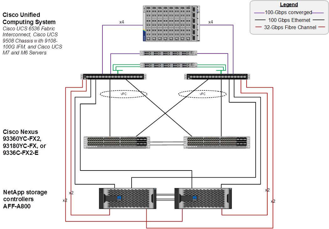
Figure 1. FlexPod Datacenter Components
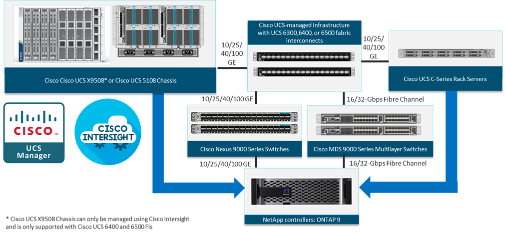
All the FlexPod components have been integrated so that you can deploy the solution quickly and economically while eliminating many of the risks associated with researching, designing, building, and deploying similar solutions from the foundation. One of the main benefits of FlexPod is its ability to maintain consistency at scale. Each of the component families shown in Figure 1 (Cisco UCS, Cisco Nexus, Cisco MDS, and NetApp controllers) offers platform and resource options to scale up or scale out the infrastructure while supporting the same features.
The FlexPod Datacenter solution with Cisco UCS M7 is built using the following hardware components:
· Cisco UCS X9508 Chassis with Cisco UCSX-I-9108-100G Intelligent Fabric Modules and up to eight Cisco UCS X210c M7 or X210c M6 Compute Nodes
· Fifth-generation Cisco UCS 6536 Fabric Interconnects to support 10/25/40/100GbE and 16/32GbFC connectivity from various components
· Cisco UCS C220 M7 or C240 M7 Rack Mount Servers attached directly to the Fabric Interconnects
· High-speed Cisco NX-OS-based Cisco Nexus 93360YC-FX2 switching design to support up to 100GE connectivity and optional 32G FC connectivity
· Cisco MDS 9132T switches to support 32G FC connectivity or Cisco MDS 9124V switches to support current 32G FC connectivity and future 64G FC connectivity
· NetApp AFF A800 (and AFF A400) end-to-end NVMe storage with up to 100GE connectivity and 32G FC connectivity
The software components of the solution consist of:
· Cisco Intersight platform to deploy the Cisco UCS components and maintain and support the FlexPod components
· Cisco Intersight Assist Virtual Appliance to help connect NetApp AIQUM, Cisco Nexus Switches, Cisco MDS Switches, and VMware vCenter to Cisco Intersight
· NetApp Active IQ Unified Manager to monitor and manage the storage and for NetApp ONTAP integration with Cisco Intersight
· VMware vCenter to set up and manage the virtual infrastructure as well as Cisco Intersight integration
Infrastructure as Code with Ansible
This FlexPod solution provides a fully automated solution deployment that explains all sections of the infrastructure and application layer. The configuration of the NetApp ONTAP Storage, Cisco Network and Compute, and VMware layers are automated by leveraging Ansible playbooks that have been developed to setup the components as per the solution best practices that were identified during the testing and validation.
Note: There are two modes to configure Cisco UCS, one is UCSM (UCS Managed) and the other is IMM (Intersight Managed Mode). Here, the Ansible scripts will configure Cisco UCS in IMM mode.
The automated deployment using Ansible provides a well-defined sequence of execution across the different constituents of this solution. Certain phases of the deployment also involve the exchange of parameters or attributes between compute, network, storage, and virtualization and also involve some manual intervention. All phases have been clearly demarcated and the implementation with automation is split into equivalent phases via Ansible playbooks with a tag-based execution of a specific section of the component’s configuration.
Figure 2. Infrastructure as Code with Ansible
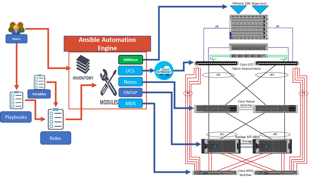
As illustrated in Figure 2, the Ansible playbooks to configure the different sections of the solution invoke a set of Roles and consume the associated variables that are required to setup the solution. The variables needed for this solution can be split into two categories – user input and defaults/ best practices. Based on the installation environment, you can choose to modify the variables to suit your requirements and proceed with the automated installation.
Note: The automation for ONTAP is scalable in nature that can configure anywhere from a single HA pair to a fully scaled 24 node ONTAP cluster.
After the base infrastructure is setup with NetApp ONTAP, Cisco Network and Compute, and VMware, you can also deploy the FlexPod Management Tools like ONTAP Tools for VMware vSphere (formerly Virtual Storage Console), SnapCenter Plug-in for VMware vSphere, and Active IQ Unified Manager in an automated fashion.
Cisco Unified Computing System X-Series
The Cisco UCS X-Series Modular System is designed to take the current generation of the Cisco UCS platform to the next level with its future-ready design and cloud-based management. Decoupling and moving the platform management to the cloud allows Cisco UCS to respond to your feature and scalability requirements in a much faster and efficient manner. Cisco UCS X-Series state of the art hardware simplifies the data-center design by providing flexible server options. A single server type, supporting a broader range of workloads, results in fewer different data center products to manage and maintain. The Cisco Intersight cloud-management platform manages Cisco UCS X-Series as well as integrating with third-party devices, including VMware vCenter and NetApp storage, to provide visibility, optimization, and orchestration from a single platform, thereby driving agility and deployment consistency.
Figure 3. Cisco UCS X9508 Chassis
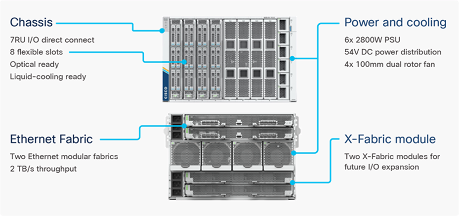
Cisco UCS X9508 Chassis
The Cisco UCS X-Series chassis is engineered to be adaptable and flexible. As seen in Figure 4, the Cisco UCS X9508 chassis has only a power-distribution midplane. This midplane-free design provides fewer obstructions for better airflow. For I/O connectivity, vertically oriented compute nodes intersect with horizontally oriented fabric modules, allowing the chassis to support future fabric innovations. Cisco UCS X9508 Chassis’ superior packaging enables larger compute nodes, thereby providing more space for actual compute components, such as memory, GPU, drives, and accelerators. Improved airflow through the chassis enables support for higher power components, and more space allows for future thermal solutions (such as liquid cooling) without limitations.
Figure 4. Cisco UCS X9508 Chassis – Midplane Free Design
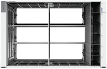
The Cisco UCS X9508 7-Rack-Unit (7RU) chassis has eight flexible slots. These slots can house a combination of compute nodes and a pool of current and future I/O resources that includes GPU accelerators, disk storage, and nonvolatile memory. At the top rear of the chassis are two Intelligent Fabric Modules (IFMs) that connect the chassis to upstream Cisco UCS 6400 or 6500 Series Fabric Interconnects. At the bottom rear of the chassis are slots to house X-Fabric modules that can flexibly connect the compute nodes with I/O devices. Six 2800W Power Supply Units (PSUs) provide 54V power to the chassis with N, N+1, and N+N redundancy. A higher voltage allows efficient power delivery with less copper and reduced power loss. Efficient, 100mm, dual counter-rotating fans deliver industry-leading airflow and power efficiency, and optimized thermal algorithms enable different cooling modes to best support the your environment.
Cisco UCSX-I-9108-100G Intelligent Fabric Modules
In the end-to-end 100Gbps Ethernet design, for the Cisco UCS X9508 Chassis, the network connectivity is provided by a pair of Cisco UCSX-I-9108-100G Intelligent Fabric Modules (IFMs). Like the fabric extenders used in the Cisco UCS 5108 Blade Server Chassis, these modules carry all network traffic to a pair of Cisco UCS 6536 Fabric Interconnects (FIs). IFMs also host the Chassis Management Controller (CMC) for chassis management. In contrast to systems with fixed networking components, Cisco UCS X9508’s midplane-free design enables easy upgrades to new networking technologies as they emerge making it straightforward to accommodate new network speeds or technologies in the future.
Figure 5. Cisco UCSX-I-9108-100G Intelligent Fabric Module
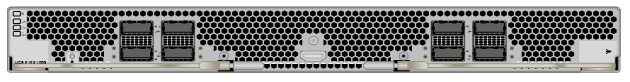
Each IFM supports eight 100Gb uplink ports for connecting the Cisco UCS X9508 Chassis to the FIs and 8 100Gb or 32 25Gb server ports for the eight compute nodes. IFM server ports can provide up to 200 Gbps of unified fabric connectivity per compute node across the two IFMs. The uplink ports connect the chassis to the Cisco UCS FIs, providing up to 1600Gbps connectivity across the two IFMs. The unified fabric carries management, VM, and Fibre Channel over Ethernet (FCoE) traffic to the FIs, where server management traffic is routed to the Cisco Intersight cloud operations platform, FCoE traffic is forwarded to either native Fibre Channel interfaces through unified ports on the FI (to Cisco MDS switches) or to FCoE uplinks (to Cisco Nexus switches supporting SAN switching), and data Ethernet traffic is forwarded upstream to the data center network (using Cisco Nexus switches).
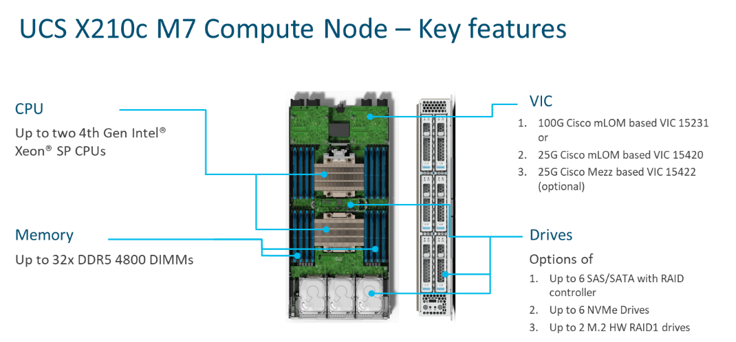
Cisco UCS X210c M7 Compute Node
The Cisco UCS X9508 Chassis is designed to host up to 8 Cisco UCS X210c M7 or X210c M6 Compute Nodes. The hardware details of the Cisco UCS X210c M7 Compute Nodes are shown in Figure 6:
Figure 6. Cisco UCS X210c M7 Compute Node
The Cisco UCS X210c M6 features:
· CPU: Up to 2x 4th Gen Intel Xeon Scalable Processors with up to 60 cores per processor and 2.625 MB Level 3 cache per core and up to 112.5 MB per CPU.
· Memory: Up to 32 x 256 GB DDR5-4800 DIMMs for a maximum of 8 TB of main memory.
· Disk storage: Up to 6 SAS or SATA drives or NVMe drives can be configured with the choice of an internal RAID controller or passthrough controllers. 2 M.2 memory cards can be added to the Compute Node with optional hardware RAID.
· GPUs: The optional front mezzanine GPU module allows support for up to two HHHL GPUs. Adding a mezzanine card and a Cisco UCS X440p PCIe Node allows up to four more GPUs to be supported with an X210c M7.
· Virtual Interface Card (VIC): Up to 2 VICs including an mLOM Cisco UCS VIC 15231 or an mLOM Cisco UCS VIC 15420 and a mezzanine Cisco UCS VIC card 15422 can be installed in a Compute Node.
· Security: The server supports an optional Trusted Platform Module (TPM). Additional security features include a secure boot FPGA and ACT2 anticounterfeit provisions.
Cisco UCS Virtual Interface Cards (VICs)
Cisco UCS X210c M7 Compute Nodes support the following Cisco UCS VIC cards:
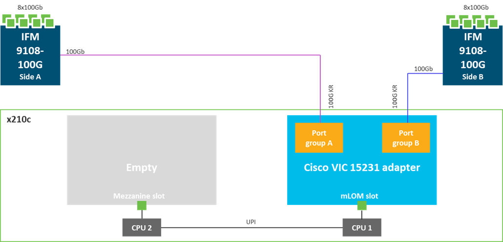
Cisco UCS VIC 15231
Cisco UCS VIC 15231 fits the mLOM slot in the Cisco UCS X210c Compute Node and enables up to 100 Gbps of unified fabric connectivity to each of the chassis IFMs for a total of 200 Gbps of connectivity per server. Cisco UCS VIC 15231 connectivity to the IFM and up to the fabric interconnects is delivered through 100Gbps. Cisco UCS VIC 15231 supports 512 virtual interfaces (both FCoE and Ethernet) along with the latest networking innovations such as NVMeoF over FC or TCP, VxLAN/NVGRE offload, and so forth.
Figure 7. Cisco UCS VIC 15231 in Cisco UCS X210c M7
Cisco UCS VIC 15420
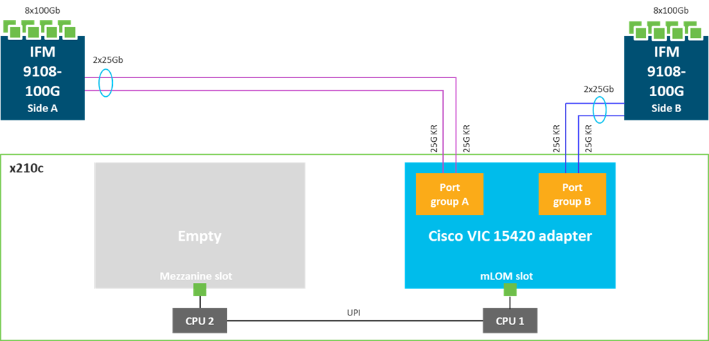
Cisco UCS VIC 15420 fits the mLOM slot in the Cisco X210c Compute Node and enables up to 50 Gbps of unified fabric connectivity to each of the chassis IFMs for a total of 100 Gbps of connectivity per server. Cisco UCS VIC 15420 connectivity to the IFM and up to the fabric interconnects is delivered through 4x 25-Gbps connections, which are configured automatically as 2x 50-Gbps port channels. Cisco UCS VIC 15420 supports 512 virtual interfaces (both Fibre Channel and Ethernet) along with the latest networking innovations such as NVMeoF over RDMA (ROCEv2), VxLAN/NVGRE offload, and so on.
Figure 8. Single Cisco UCS VIC 15420 in Cisco UCS X210c M7
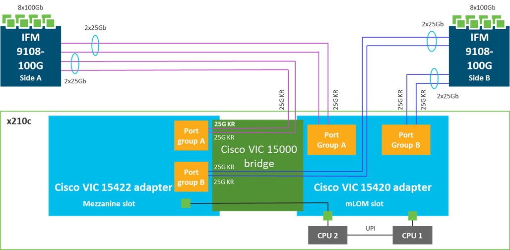
Cisco UCS VIC 15422
The optional Cisco UCS VIC 15422 fits the mezzanine slot on the server. A bridge card (UCSX-V5-BRIDGE) extends this VIC’s 2x 50 Gbps of network connections up to the mLOM slot and out through the mLOM’s IFM connectors, bringing the total bandwidth to 100 Gbps per fabric for a total bandwidth of 200 Gbps per server.
Figure 9. Cisco UCS VIC 15420 and 15422 in Cisco UCS X210c M7
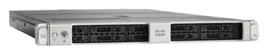
Cisco UCS C220 M7 Rack Server
Figure 10. Cisco UCS C220 M7 Rack Server
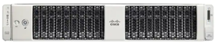
Cisco UCS C240 M7 Rack Server
The Cisco UCS C240 M7 Rack Server also extends the capabilities of the Cisco UCS rack server portfolio with the addition of up to two 4th Gen Intel Xeon Scalable CPUs, with up to 60 cores per socket. The maximum memory capacity for 2 CPUs is 8 TB (for 32 x 256 GB DDR5 4800 MT/s DIMMs). The Cisco UCS C240 M7 has a 2-Rack-Unit (RU) form and supports up to 8 PCIe 4.0 slots or up to 4 PCIe 5.0 slots plus a modular LAN on motherboard (mLOM) slot. Up to five GPUs are supported. This server can connect directly to the Cisco UCS 6536 Fabric Interconnects at 2x100Gbps with 5th Generation Cisco UCS VIC 15238 (mLOM-based) or 15235 (PCIe-based). This server can also connect directly to the Cisco UCS 6536 Fabric Interconnects via 4x25G to 100G breakout cables with the 5th Generation Cisco UCS VIC 15428 (mLOM-based) or 15425 (PCIe-based). The Cisco UCS C-series servers can also connect to the Cisco UCS FI 6536 using the Cisco Nexus 93180YC-FX3 in FEX-mode.
Figure 11. Cisco UCS C240 M7 Rack Server
Cisco UCS 6536 Fabric Interconnects
The Cisco UCS Fabric Interconnects (FIs) provide a single point for connectivity and management for the entire Cisco Unified Computing System. Typically deployed as an active/active pair, the system’s FIs integrate all components into a single, highly available management domain controlled by Cisco Intersight. Cisco UCS FIs provide a single unified fabric for the system, with low-latency, lossless, cut-through switching that supports LAN, SAN, and management traffic using a single set of cables.
Note: Currently, the Cisco UCS X-Series does not support Cisco UCS Manager.
Figure 12. Cisco UCS 6536 Fabric Interconnect

The Cisco UCS 6536 utilized in the current design is a 36-port Fabric Interconnect. This single RU device includes up to 36 10/25/40/100 Gbps Ethernet ports, 16 8/16/32-Gbps Fibre Channel ports via 4 128 Gbps to 4x32 Gbps breakouts on ports 33-36. All 36 ports support breakout cables or QSA interfaces.
The Cisco Intersight platform is a Software-as-a-Service (SaaS) infrastructure lifecycle management platform that delivers simplified configuration, deployment, maintenance, and support. The Cisco Intersight platform is designed to be modular, so you can adopt services based on your individual requirements. The platform significantly simplifies IT operations by bridging applications with infrastructure, providing visibility and management from bare-metal servers and hypervisors to serverless applications, thereby reducing costs and mitigating risk. This unified SaaS platform uses a unified Open API design that natively integrates with third-party platforms and tools.
Figure 13. Cisco Intersight Overview
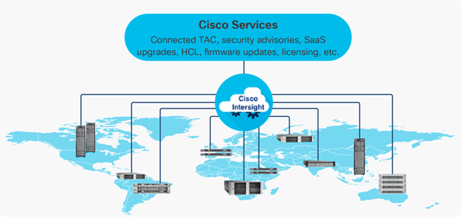
The main benefits of Cisco Intersight infrastructure services are as follows:
· Simplify daily operations by automating many daily manual tasks
· Combine the convenience of a SaaS platform with the capability to connect from anywhere and manage infrastructure through a browser or mobile app
· Stay ahead of problems and accelerate trouble resolution through advanced support capabilities
· Gain global visibility of infrastructure health and status along with advanced management and support capabilities
· Upgrade to add workload optimization and other services when needed
Cisco Intersight Virtual Appliance and Private Virtual Appliance
In addition to the SaaS deployment model running on Intersight.com, on-premises options can be purchased separately. The Cisco Intersight Virtual Appliance and Cisco Intersight Private Virtual Appliance are available for organizations that have additional data locality or security requirements for managing systems. The Cisco Intersight Virtual Appliance delivers the management features of the Cisco Intersight platform in an easy-to-deploy VMware Open Virtualization Appliance (OVA) or Microsoft Hyper-V Server virtual machine that allows you to control the system details that leave your premises. The Cisco Intersight Private Virtual Appliance is provided in a form factor specifically designed for users who operate in disconnected (air gap) environments. The Private Virtual Appliance requires no connection to public networks or back to Cisco to operate.
Cisco Intersight Assist
Cisco Intersight Assist helps you add endpoint devices to Cisco Intersight. A data center could have multiple devices that do not connect directly with Cisco Intersight. Any device that is supported by Cisco Intersight, but does not connect directly with it, will need a connection mechanism. Cisco Intersight Assist provides that connection mechanism. In FlexPod, VMware vCenter, NetApp Active IQ Unified Manager, Cisco Nexus Switches, and Cisco MDS switches connect to Intersight with the help of the Intersight Assist VM.
Cisco Intersight Assist is available within the Cisco Intersight Virtual Appliance, which is distributed as a deployable virtual machine contained within an Open Virtual Appliance (OVA) file format. More details about the Cisco Intersight Assist VM deployment configuration is explained in later sections.
Licensing Requirements
The Cisco Intersight platform uses a new subscription-based license model now with two tiers. You can purchase a subscription duration of one, three, or five years and choose the required Cisco UCS server volume tier for the selected subscription duration. For Cisco UCS M6 and below servers, each Cisco endpoint can be claimed into Intersight at no additional cost (no license) and can access base-level features listed in the Intersight Licensing page referenced below. All Cisco UCS M7 servers require either an Essentials or Advantage license listed below. You can purchase any of the following Cisco Intersight licenses using the Cisco ordering tool:
· Cisco Intersight Essentials: the Essentials includes Lifecycle Operations features, including Cisco UCS Central and Cisco UCS-Manager entitlements, policy-based configuration with server profiles (IMM), firmware management, Global Monitoring and Inventory, Custom Dashboards, and evaluation of compatibility with the Cisco Hardware Compatibility List (HCL). Also, Essentials includes Proactive Support features, including Proactive RMA, Connected TAC, Advisories, and Sustainability.
· Cisco Intersight Advantage: Advantage offers all the features of the Essentials tier plus In-Platform Automation features such as Tunneled KVM, Operating System Install Automation, Storage/Virtualization/Network Automation, and Workflow Designer. It also includes Ecosystem Integrations for Ecosystem Visibility, Operations, and Automation, and ServiceNow Integration.
Servers in the Cisco Intersight Managed Mode require at least the Essentials license. For more information about the features provided in the various licensing tiers, see https://intersight.com/help/saas/getting_started/licensing_requirements/lic_infra.
Cisco UCS and Intersight Security
From a Security perspective, all Cisco UCS user interfaces are hardened with the latest security ciphers and protocols including redirection of http to https, password and password expiry policies, integration with secure authentication systems, and so on. Additionally, Cisco UCS servers support confidential computing (both Intel SGX and AMD based), although confidential computing is not addressed in this CVD. Finally, almost all Cisco UCS servers now sold come with Trusted Platform Modules (TPMs), that in VMware allows attestation of Unified Extended Firmware Interface Forum (UEFI) secure boot, which allows only securely signed code to be loaded. Many of the latest available operating systems, such as Microsoft Windows 11 require a TPM. The latest versions of VMware allow the assignment of a virtual TPM to VMs running operating systems that require a TPM.
The Cisco Nexus 9000 Series Switches offer both modular and fixed 1/10/25/40/100 Gigabit Ethernet switch configurations with scalability up to 60 Tbps of nonblocking performance with less than five-microsecond latency, wire speed VXLAN gateway, bridging, and routing support.
Figure 14. Cisco Nexus 933360YC-FX2 Switch
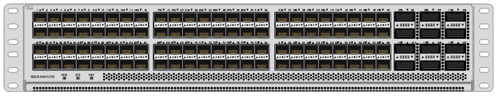
The Cisco Nexus 9000 series switch featured in this design is the Cisco Nexus 93360YC-FX2 configured in NX-OS standalone mode. NX-OS is a purpose-built data-center operating system designed for performance, resiliency, scalability, manageability, and programmability at its foundation. It provides a robust and comprehensive feature set that meets the demanding requirements of virtualization and automation.
The Cisco Nexus 93360YC-FX2 Switch is a 2RU switch that supports 7.2 Tbps of bandwidth and 2.4 bpps. The 96 downlink ports on the Cisco Nexus 93360YC-FX2 can support 1-, 10-, or 25-Gbps Ethernet or 16- or 32-Gbps Fibre Channel ports, offering deployment flexibility and investment protection. The 12 uplink ports can be configured as 40- or 100-Gbps Ethernet, offering flexible migration options. This switch was chosen for this solution because of the extra flexibility and scaling the 12 40- or 100-Gbps uplink ports offer.
The Cisco Nexus 93180YC-FX, 93360YC-FX2, and 9336C-FX2-E switches now support SAN switching, allowing both Ethernet and Fibre Channel SAN switching in a single switch. In addition to 16- or 32-Gbps Fibre Channel, these switches also support 100-Gbps FCoE, allowing port-channeled 100-Gbps FCoE uplinks from the Cisco UCS 6536 Fabric Interconnects to Cisco Nexus switches in SAN switching mode.
Cisco MDS 9132T 32G Multilayer Fabric Switch
The Cisco MDS 9132T 32G Multilayer Fabric Switch is the current generation of the highly reliable, flexible, and low-cost Cisco MDS 9100 Series switches. It combines high performance with exceptional flexibility and cost effectiveness. This powerful, compact one Rack-Unit (1RU) switch scales from 8 to 32 line-rate 32 Gbps Fibre Channel ports.
Figure 15. Cisco MDS 9132T 32G Multilayer Fabric Switch
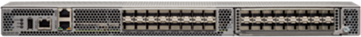
The Cisco MDS 9132T delivers advanced storage networking features and functions with ease of management and compatibility with the entire Cisco MDS 9000 family portfolio for reliable end-to-end connectivity. This switch also offers state-of-the-art SAN analytics and telemetry capabilities that have been built into this next-generation hardware platform. This new state-of-the-art technology couples the next-generation port ASIC with a fully dedicated network processing unit designed to complete analytics calculations in real time. The telemetry data extracted from the inspection of the frame headers are calculated on board (within the switch) and, using an industry-leading open format, can be streamed to any analytics-visualization platform. This switch also includes a dedicated 10/100/1000BASE-T telemetry port to maximize data delivery to any telemetry receiver, including Cisco Data Center Network Manager.
Cisco MDS 9124V 64G 24-Port Fibre Channel Switch
The next-generation Cisco MDS 9124V 64-Gbps 24-Port Fibre Channel Switch (Figure 16) supports 64, 32, and 16 Gbps Fibre Channel ports and provides high-speed Fibre Channel connectivity for all-flash arrays and high-performance hosts. This switch offers state-of-the-art analytics and telemetry capabilities built into its next-generation Application-Specific Integrated Circuit (ASIC) chipset. This switch allows seamless transition to Fibre Channel Non-Volatile Memory Express (NVMe/FC) workloads whenever available without any hardware upgrade in the SAN. It empowers small, midsize, and large enterprises that are rapidly deploying cloud-scale applications using extremely dense virtualized servers, providing the benefits of greater bandwidth, scale, and consolidation. This switch is now orderable from Cisco, is supported in FlexPod, but was not validated in this design.
Figure 16. Cisco MDS 9124V 64G 24-Port Fibre Channel Switch
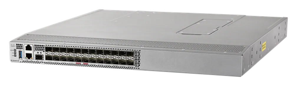
The Cisco MDS 9124V delivers advanced storage networking features and functions with ease of management and compatibility with the entire Cisco MDS 9000 family portfolio for reliable end-to-end connectivity. This switch also offers state-of-the-art SAN analytics and telemetry capabilities that have been built into this next-generation hardware platform. This new state-of-the-art technology couples the next-generation Cisco port ASIC with a fully dedicated network processing unit designed to complete analytics calculations in real time. The telemetry data extracted from the inspection of the frame headers are calculated on board (within the switch) and, using an industry-leading open format, can be streamed to any analytics-visualization platform. This switch also includes a dedicated 10/100/1000BASE-T telemetry port to maximize data delivery to any telemetry receiver, including Cisco Data Center Network Manager. The Cisco MDS 9148V 48-Port Fibre Channel Switch is also available when more ports are needed.
Cisco Nexus Dashboard Fabric Controller (NDFC) SAN
Cisco NDFC SAN can be used to monitor, configure, and analyze Cisco 32Gbps Fibre Channel fabrics. Cisco NDFC SAN is deployed as an app on Cisco Nexus Dashboard. A single-server instance of the virtualized Nexus Dashboard with NDFC SAN and SAN Analytics is supported. Once the Cisco MDS switches and Cisco UCS Fabric Interconnects are added with the appropriate credentials and licensing, monitoring of the SAN fabrics can begin. Additionally, VSANs, device aliases, zones, and zone sets can be added, modified, and deleted using the NDFC point-and-click interface. Device Manager can also be used to configure the Cisco MDS switches. SAN Analytics can be added to Cisco MDS switches to provide insights into the fabric by allowing you to monitor, analyze, identify, and troubleshoot performance issues.
NetApp AFF A-Series controller lineup provides industry leading performance while continuing to provide a full suite of enterprise-grade data services for a shared environment across on-premises data centers and the cloud. Powered by NetApp ONTAP data management software, NetApp AFF A-Series systems deliver the industry’s highest performance, superior flexibility, and best-in-class data services and cloud integration to help you accelerate, manage, and protect business-critical data across your hybrid clouds. As the first enterprise-grade storage systems to support both FC-NVMe and NVMe-TCP, AFF A-Series systems boost performance with modern network connectivity. These systems deliver the industry’s lowest latency for an enterprise all-flash array, making them a superior choice for running the most demanding workloads and AI/DL applications. With a simple software upgrade to the modern FC-NVMe or NVMe-TCP SAN infrastructure, you can run more workloads with faster response times, without disruption or data migration.
NetApp offers a wide range of AFF-A series controllers to meet varying demands of the field. The high-end NetApp AFF A900 systems have a highly resilient design that enables non-disruptive in-chassis upgrades. It delivers latency as low as 100µs with FC-NVMe technology. The NetApp AFF A800 delivers high performance in a compact form factor and is especially suited for EDA and Media & Entertainment workloads. The midrange, most versatile NetApp AFF A400 system features hardware acceleration technology that significantly enhances performance and storage efficiency. The budget friendly, the NetApp AFF A150 is an excellent entry-level performance flash option for you.
NetApp AFF A150
The NetApp AFF A150 entry-level performance all-flash array provides 40% more performance compared with its predecessor. In addition to the performance enhancement, the NetApp AFF A150 system also supports more expansion options than its predecessor. It supports 24 internal 960GB, 3.8TB, and 7.6TB SAS SSD drives and up to two external expansion shelves for a maximum of 72 SAS SSDs per HA pair. The flexible NetApp AFF A150 system can be tailored to meet various solution requirements, including starting very small with 8 x 960GB SSD drives.
The NetApp AFF A150 offers 10GbE ports for IP based transport or Unified Target Adapter 2 (UTA2) ports for either 10GbE Ethernet connectivity for IP-based traffic or 16Gb FC connectivity for FC and FC-NVMe traffic. The two miniSAS ports can be used to connect up to two expansion shelves per HA pair. Additional NetApp AFF A150, or compatible AFF / FAS HA pairs, can be added to the cluster to scale out the solution to meet the performance requirements, subject to the platform mixing rules and support limits. You can start protecting your business with NetApp AFF A150 by taking advantage of the ONTAP data protection features to create instantaneous Snapshots, set up SnapMirror data replication, and deploy MetroCluster IP or SnapMirror Business Continuity solutions for disaster recovery and to ensure business continuity.
Figure 17. NetApp AFF A150 Front View

Figure 18. NetApp AFF A150 Rear View (with UTA2)
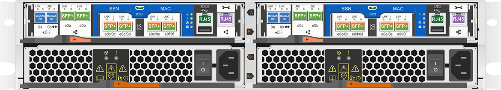
NetApp AFF A400
The NetApp AFF A400 offers full end-to-end NVMe support. The frontend FC-NVMe connectivity makes it possible to achieve optimal performance from an all-flash array for workloads that include artificial intelligence, machine learning, and real-time analytics as well as business-critical databases. The frontend NVMe-TCP connectivity enables you to take advantage of NVMe technology over existing ethernet infrastructure for faster host connectivity. On the back end, the NetApp AFF A400 supports both serial-attached SCSI (SAS) and NVMe-attached SSDs, offering the versatility for you to move up from your legacy A-Series systems and satisfying the increasing interest in NVMe-based storage.
The NetApp AFF A400 offers greater port availability, network connectivity, and expandability. The NetApp AFF A400 has 10 PCIe Gen3 slots per high availability pair. The NetApp AFF A400 offers 10GbE, 25GbE and 100GbE ports for IP based transport, and 16/32Gb ports for FC and FC-NVMe traffic. This model was created to keep up with changing business needs and performance and workload requirements by merging the latest technology for data acceleration and ultra-low latency in an end-to-end NVMe storage system.
Figure 19. NetApp AFF A400 Front View
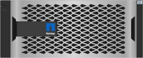
Figure 20. NetApp AFF A400 Rear View

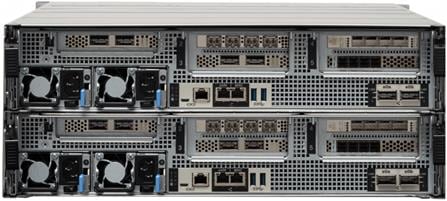
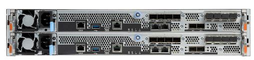
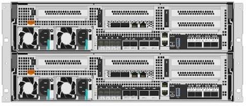
NetApp AFF A800
The NetApp AFF A800 is a higher end model that offers superior performance and higher port count (both 32G FC and 100G Ethernet) than NetApp AFF A400. NetApp AFF A800 single chassis HA Pair supports 48 internal SSD drives and up to 8 external NS224 shelves allowing up to 240 NVMe SSD drives. It offers ultra-low latency of 100us and up to 300 GB/s throughput enabling it to be an ultimate choice to power data hungry applications such as artificial intelligence, deep learning, and big data analytics.
Figure 21. NetApp AFF A800 Front View
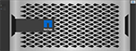
Figure 22. NetApp AFF A800 Rear View
For more information about the NetApp AFF A-series controllers, see the NetApp AFF product page: https://www.netapp.com/us/products/storage-systems/all-flash-array/aff-a-series.aspx.
You can view or download more technical specifications of the NetApp AFF A-series controllers here: https://www.netapp.com/pdf.html?item=/media/7828-DS-3582-AFF-A-Series.pdf
NetApp AFF C-Series Storage systems help move more data to flash with the latest high-density NVMe QLC capacity flash technology. These systems are suited for large-capacity deployment with a small footprint as an affordable way to modernize data center to all flash and also connect to the cloud. Powered by NetApp ONTAP data management software, NetApp AFF C-Series systems deliver industry-leading efficiency, superior flexibility, and best-in-class data services and cloud integration to help scale IT infrastructure, simplify data management, reduce storage cost, rack space usage, power consumption, and improve sustainability significantly.
NetApp offers several AFF-C series controllers to meet varying demands of the field. The high-end NetApp AFF C800 systems offer superior performance. The midrange NetApp AFF C400 delivers high performance and good expansion capability. The entry-level NetApp AFF C250 system balanced performance, connectivity, and expansion options for a small footprint deployment.
NetApp AFF C250
The NetApp AFF C250 is an entry-level small form-factor capacity flash model. The 2U dual-controller system supports 24 internal drives for space efficient deployment. The NetApp AFF C250 offers scale-out performance, storage expansion, flexibility in network connectivity, and a rich set of data management and data protection capabilities powered by NetApp ONTAP software.
The NetApp AFF C250 offers both 25 GbE and 100 GbE Ethernet connectivity as well as 32Gb FC connectivity for deploying reliable Ethernet and FC solutions. By adding external NVMe expansion shelves for additional NVMe QLC SSD, the platform is capable of meeting the substantial capacity needs of the data centers.
Figure 23. NetApp AFF C250 Front View

Figure 24. NetApp AFF C250 Rear View
NetApp AFF C400
The NetApp AFF C400 is a midrange model which offers full end-to-end NVMe support. The frontend FC-NVMe and NVMe-TCP connectivity enables you to take advantage of NVMe technology over existing FC and Ethernet infrastructure for faster host connectivity. On the back end, the NetApp AFF C400 supports both serial-attached SCSI (SAS) and NVMe-attached SSDs, offering the versatility for you to move up from your existing systems and adopt NVMe-based storage.
Compared to the entry-level NetApp AFF C250 model, the NetApp AFF C400 offers greater port availability, network connectivity, and expandability. The NetApp AFF C400 has 10 PCIe Gen3 slots per high availability pair. The NetApp AFF C400 offers 10GbE, 25GbE and 100GbE ports for IP based transport, and 16/32Gb ports for FC and FC-NVMe traffic.
Figure 25. NetApp AFF C400 Front View
Figure 26. NetApp AFF C400 Rear View
NetApp AFF C800
The NetApp AFF C800 is a higher end model that offers superior performance and higher port count (both 32G FC and 100G Ethernet) than NetApp AFF C400. The NetApp AFF C800 single chassis HA Pair supports 48 internal SSD drives and up to 8 external NS224 shelves allowing up to 240 NVMe SSD drives. It is an ultimate choice to power data hungry applications such as artificial intelligence, deep learning, and big data analytics.
Figure 27. NetApp AFF C800 Front View
Figure 28. NetApp AFF C800 Rear View

For more information about the NetApp AFF C-series controllers, see the NetApp AFF C-Series product page: https://www.netapp.com/data-storage/aff-c-series/
You can view or download more technical specifications of the NetApp AFF C-Series controllers here: https://www.netapp.com/media/81583-da-4240-aff-c-series.pdf
You can look up the detailed NetApp storage product configurations and limits here: https://hwu.netapp.com/
Note: FlexPod CVDs provide reference configurations and there are many more supported IMT configurations that can be used for FlexPod deployments, including NetApp hybrid storage arrays.
NetApp ONTAP 9.12.1
NetApp storage systems harness the power of ONTAP to simplify the data infrastructure from edge, core, and cloud with a common set of data services and 99.9999 percent availability. NetApp ONTAP 9 data management software from NetApp enables you to modernize your infrastructure and transition to a cloud-ready data center. NetApp ONTAP 9 has a host of features to simplify deployment and data management, accelerate and protect critical data, and make infrastructure future-ready across hybrid-cloud architectures.
NetApp ONTAP 9 is the data management software that is used with the NetApp AFF A400 and A800 all-flash storage systems in this solution design. NetApp ONTAP software offers secure unified storage for applications that read and write data over block- or file-access protocol storage configurations. These storage configurations range from high-speed flash to lower-priced spinning media or cloud-based object storage. NetApp ONTAP implementations can run on NetApp engineered AFF, FAS, or ASA series arrays and in private, public, or hybrid clouds (NetApp Private Storage and NetApp Cloud Volumes ONTAP). Specialized implementations offer best-in-class converged infrastructure, featured here as part of the FlexPod Datacenter solution or with access to third-party storage arrays (NetApp FlexArray virtualization). Together these implementations form the basic framework of the NetApp Data Fabric, with a common software-defined approach to data management, and fast efficient replication across systems. FlexPod and ONTAP architectures can serve as the foundation for both hybrid cloud and private cloud designs.
The NetApp AFF C-Series family of capacity flash storage system comes with NetApp ONTAP One, the all-in-one software license for on-premises operations. At any time, you can start using and taking advantage of the rich Netapp ONTAP data management capabilities.
Read more about the capabilities of NetApp ONTAP data management software here: https://www.netapp.com/us/products/data-management-software/ontap.aspx.
For more information on new features and functionality in latest NetApp ONTAP software, refer to the NetApp ONTAP release notes: NetApp ONTAP 9 Release Notes (netapp.com)
Note: The support for the NetApp AFF A150 and the NetApp AFF C-Series platforms was introduced with NetApp ONTAP 9.12.1P1.
NetApp Storage Security and Ransomware Protection
NetApp storage administrators use local or remote login accounts to authenticate themselves to the cluster and storage VM. Role-Based Access Control (RBAC) determines the commands to which an administrator has access. In addition to RBAC, NetApp ONTAP supports multi-factor authentication (MFA) and multi-admin verification (MAV) to enhance the security of the storage system.
With NetApp ONTAP, you can use the security login create command to enhance security by requiring that administrators log in to an admin or data SVM with both an SSH public key and a user password. Beginning with NetApp ONTAP 9.12.1, you can use Yubikey hardware authentication devices for SSH client MFA using the FIDO2 (Fast IDentity Online) or Personal Identity Verification (PIV) authentication standards.
With NetApp ONTAP 9.11.1, you can use multi-admin verification (MAV) to ensure that certain operations, such as deleting volumes or Snapshot copies, can be executed only after approvals from designated administrators. This prevents compromised, malicious, or inexperienced administrators from making undesirable changes or deleting data.
Also with NetApp ONTAP 9.10.1, the Autonomous Ransomware Protection (ARP) feature uses workload analysis in NAS (NFS and SMB) environments to proactively detect and warn about abnormal activity that might indicate a ransomware attack.
While NetApp ONTAP includes features like FPolicy, Snapshot copies, SnapLock, and Active IQ Digital Advisor to help protect from ransomware, ARP utilizes machine-learning and simplifies the detection of and the recovery from a ransomware attack.
ARP can detect the spread of most ransomware attacks after only a small number of files are encrypted, take action automatically to protect data, and alert you that a suspected attack is happening.
When an attack is suspected, the system takes a volume Snapshot copy at that point in time and locks that copy. If the attack is confirmed later, the volume can be restored to this proactively taken snapshot to minimize the data loss.
For more information on MFA, MAV, and ransomware protection, refer to the following:
· https://docs.netapp.com/us-en/ontap/authentication/setup-ssh-multifactor-authentication-task.html
· https://docs.netapp.com/us-en/ontap/multi-admin-verify/
· https://www.netapp.com/pdf.html?item=/media/17055-tr4647pdf.pdf
· https://docs.netapp.com/us-en/ontap/anti-ransomware/
NetApp Active IQ Unified Manager
NetApp Active IQ Unified Manager is a comprehensive monitoring and proactive management tool for NetApp ONTAP systems to help manage the availability, capacity, protection, and performance risks of your storage systems and virtual infrastructure. The Unified Manager can be deployed on a Linux server, on a Windows server, or as a virtual appliance on a VMware host.
NetApp Active IQ Unified Manager enables monitoring your NetApp ONTAP storage clusters from a single redesigned, intuitive interface that delivers intelligence from community wisdom and AI analytics. It provides comprehensive operational, performance, and proactive insights into the storage environment and the virtual machines running on it. When an issue occurs with the storage infrastructure, Unified Manager can notify you about the details of the issue to help with identifying the root cause. The virtual machine dashboard gives you a view into the performance statistics for the VM so that you can investigate the entire I/O path from the VMware vSphere host down through the network and finally to the storage. Some events also provide remedial actions that can be taken to rectify the issue. You can configure custom alerts for events so that when issues occur, you are notified through email and SNMP Traps. NetApp Active IQ Unified Manager enables planning for the storage requirements of your users by forecasting capacity and usage trends to proactively act before issues arise, preventing reactive short-term decisions that can lead to additional problems in the long term.
For more information on NetApp Active IQ Unified Manager, go to: https://docs.netapp.com/us-en/active-iq-unified-manager/
NetApp ONTAP Tools for VMware vSphere
The NetApp ONTAP tools for VMware vSphere provides end-to-end life cycle management for virtual machines in VMware environments that use NetApp storage systems. It simplifies storage and data management for VMware environment by enabling administrators to directly manage storage within the vCenter Server.
Note: Each component in NetApp ONTAP tools provides capabilities to help manage your storage more efficiently.
Virtual Storage Console (VSC)
VSC enables you to perform the following tasks:
· Add storage controllers, assign credentials, and set up permissions for storage controllers of VSC, that both SRA and VASA Provider can leverage
· Provision datastores
° Monitor the performance of the datastores and virtual machines in your vCenter Server environment
° View and update the host settings of the ESXi hosts that are connected to NetApp storage
· Manage access to the vCenter Server objects and NetApp ONTAP objects by using the vCenter Server role-based access control (RBAC) and NetApp ONTAP RBAC
VASA Provider
VASA Provider for NetApp ONTAP uses VMware vSphere APIs for Storage Awareness (VASA) to send information about storage used by VMware vSphere to the vCenter Server. NetApp ONTAP tools has VASA Provider integrated with VSC. VASA Provider enables you to perform the following tasks:
· Provision VMware Virtual Volumes (vVols) datastores
° Create and use storage capability profiles that define different storage service level objectives (SLOs) for your environment
° Verify for compliance between the datastores and the storage capability profiles
° Set alarms to warn you when volumes and aggregates are approaching the threshold limits
° Monitor the performance of virtual machine disks (VMDKs) and the virtual machines that are created on vVols datastores
Storage Replication Adapter (SRA)
SRA enables you to use array-based replication (ABR) for protected sites and recovery sites for disaster recovery in the event of a failure. When SRA is enabled and used in conjunction with VMware Site Recovery Manager (SRM), you can recover the vCenter Server datastores and virtual machines in the event of a failure.
Note: The NetApp ONTAP tools for VMware vSphere 9.12 release supports and interoperates with VMware vSphere 8.0. It also supports NVMe-oF vVols introduced with vSphere 8.0 in conjunction with Storage Policy Based Management for performance and availability requirement configurations. For more information on NetApp ONTAP tools for VMware vSphere, go to: https://docs.netapp.com/us-en/ontap-tools-vmware-vsphere/index.html
NetApp SnapCenter
SnapCenter Software is a simple, centralized, scalable platform that provides application consistent data protection for applications, databases, host file systems, and VMs running on NetApp ONTAP systems anywhere on premise or in the Hybrid Cloud.
SnapCenter leverages NetApp Snapshot, SnapRestore, FlexClone, SnapMirror, and SnapVault technologies to provide:
· Fast, space-efficient, application-consistent, disk-based backups
· Rapid, granular restore, and application-consistent recovery
· Quick, space-efficient cloning
SnapCenter includes both SnapCenter Server and individual lightweight plug-ins. You can automate deployment of plug-ins to remote application hosts, schedule backup, verification, and clone operations, and monitor all data protection operations.
Data protection is supported for Microsoft Exchange Server, Microsoft SQL Server, Oracle Databases on Linux or AIX, SAP HANA database, and Windows Host Filesystems running on NetApp ONTAP systems. It is also supported for other standard or custom applications and databases by providing a framework to create user-defined SnapCenter plug-ins. You may install only the plug-ins that are appropriate for the data that you want to protect.
Note: For more information on SnapCenter 4.8, refer to the SnapCenter software documentation: https://docs.netapp.com/us-en/snapcenter/index.html
NetApp BlueXP
NetApp BlueXP is a unified control plane that provides a hybrid multicloud experience for storage and data services across on-premises and cloud environments. NetApp BlueXP is an evolution of Cloud Manager and enables the management of your NetApp storage and data assets from a single interface.
You can use NetApp BlueXP to move, protect, and analyze data, and to control on-prem storage devices like NetApp ONTAP, E-Series, and StorgeGRID, and to create and administer cloud storage (for example, Cloud Volumes ONTAP and Azure NetApp Files).
The NetApp BlueXP backup and recovery service provides efficient, secure, and cost-effective data protection for NetApp ONTAP data, Kubernetes persistent volumes, databases, and virtual machines, both on premises and in the cloud. Backups are automatically generated and stored in an object store in your public or private cloud account.
NetApp BlueXP ransomware protection provides a single point of visibility and control to manage and to refine data security across various working environments and infrastructure layers to better respond to threats as they occur.
Note: For more information on NetApp BlueXP, go to: https://docs.netapp.com/us-en/cloud-manager-family/
VMware vSphere 8.0
VMware vSphere is a virtualization platform for holistically managing large collections of infrastructures (resources including CPUs, storage, and networking) as a seamless, versatile, and dynamic operating environment. Unlike traditional operating systems that manage an individual machine, VMware vSphere aggregates the infrastructure of an entire data center to create a single powerhouse with resources that can be allocated quickly and dynamically to any application in need.
VMware vSphere 8.0 has several improvements and simplifications including, but not limited to:
· Limits with VMware vSphere 8.0 have been increased including the number of GPU devices increased to 8, the number of ESXi hosts that can be managed by Lifecycle Manager is increased from 400 to 1000, the maximum number of VMs per cluster is increased from 8,000 to 10,000, and the number of VM DirectPath I/O devices per host is increased from 8 to 32.
· Security improvements including adding an SSH timeout on ESXi hosts, a TPM Provisioning policy allowing a vTPM to be replaced when cloning VMs, and TLS 1.2 as the minimum supported TLS version.
· Implementation of VMware vMotion Unified Data Transport (UDT) to significantly reduce the time to storage migrate powered off virtual machines.
· Lifecycle Management improvements including VMware vSphere Configuration Profiles as a new alternative to VMware Host Profiles, staging cluster images and remediating up to 10 ESXi hosts in parallel instead of one at a time.
· New Virtual Hardware in VM hardware version 20 supporting the latest guest operating systems, including Windows 11.
· Distributed Resource Scheduler and vMotion improvements.
· Implementation of the VMware Balanced Power Management Policy on each server, which reduces energy consumption with minimal performance compromise.
· Implementation of VMware Distributed Power Management, which along with configuration of the Intelligent Platform Management Interface (IPMI) on each Cisco UCS server allows a VMware host cluster to reduce its power consumption by powering hosts on and off based on cluster resource utilization.
For more information about VMware vSphere and its components, go to: https://www.vmware.com/products/vsphere.html.
VMware vSphere vCenter
VMware vCenter Server provides unified management of all hosts and VMs from a single console and aggregates performance monitoring of clusters, hosts, and VMs. VMware vCenter Server gives administrators a deep insight into the status and configuration of compute clusters, hosts, VMs, storage, the guest OS, and other critical components of a virtual infrastructure. VMware vCenter manages the rich set of features available in a VMware vSphere environment.
Cisco Intersight integrates with VMware vCenter, NetApp storage, and Cisco Nexus switches as follows:
· Cisco Intersight uses the device connector running within the Cisco Intersight Assist virtual appliance to communicate with the VMware vCenter.
· Cisco Intersight uses the device connector running within a Cisco Intersight Assist virtual appliance to integrate with NetApp Active IQ Unified Manager. The NetApp AFF A400/A800 should be added to NetApp Active IQ Unified Manager.
· Cisco Intersight uses the device connector running within the Cisco Intersight Assist virtual appliance to communicate with Cisco Nexus 9000 and MDS switches.
Figure 29. Cisco Intersight and vCenter/NetApp/Cisco Switch Integration
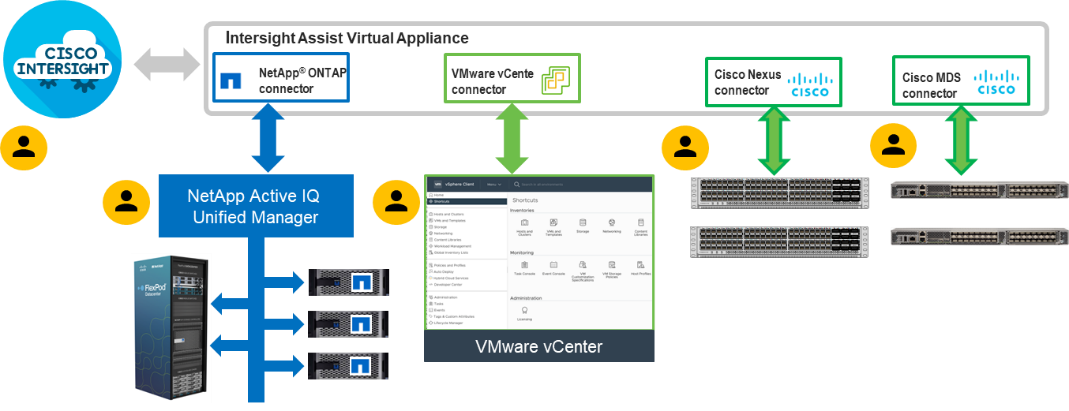
The device connector provides a secure way for connected targets to send information and receive control instructions from the Cisco Intersight portal using a secure internet connection. The integration brings the full value and simplicity of Cisco Intersight infrastructure management service to VMware hypervisor and NetApp ONTAP data storage environments.
Enterprise SAN and NAS workloads can benefit equally from the integrated management solution. The integration architecture enables FlexPod you to use new management capabilities with no compromise in their existing VMware, NetApp ONTAP, or switch operations. IT users will be able to manage heterogeneous infrastructure from a centralized Cisco Intersight portal. At the same time, the IT staff can continue to use VMware vCenter, NetApp Active IQ Unified Manager, and Cisco Switch Interfaces for comprehensive analysis, diagnostics, and reporting of virtual, storage, and switching environments. The functionality provided through this integration is explained in the upcoming solution design section.
Solution Design
This chapter contains the following:
· Cisco Nexus Ethernet Connectivity
· Cisco MDS SAN Connectivity - Fibre Channel Design Only
· Cisco UCS X-Series Configuration - Cisco Intersight Managed Mode
· NetApp AFF – Storage Virtual Machine (SVM) Design
· VMware vSphere - ESXi Design
· Cisco Intersight Integration with VMware vCenter, NetApp Storage, and Cisco Switches
The FlexPod Datacenter with Cisco UCS M7 solution delivers a cloud-managed infrastructure solution on the latest Cisco UCS hardware. The VMware vSphere 8.0 hypervisor is installed on the Cisco UCS X210c M7 Compute Nodes and Cisco UCS C220 M7 and C240 M7 servers configured for stateless compute design using boot from SAN. The NetApp AFF A800 or A400 provides the storage infrastructure required for setting up the VMware environment. The Cisco Intersight cloud-management platform is utilized to configure and manage the infrastructure.
The FlexPod Datacenter with Cisco UCS M7 design meets the following general design requirements:
· Resilient design across all layers of the infrastructure with no single point of failure
· Scalable design with the flexibility to add compute capacity, storage, or network bandwidth as needed
· Modular design that can be replicated to expand and grow as the needs of the business grow
· Flexible design that can support different models of various components with ease
· Simplified design with ability to integrate and automate with external automation tools
· Cloud-enabled design which can be configured, managed, and orchestrated from the cloud using GUI or APIs
FlexPod Datacenter with Cisco UCS M7 supports both IP and Fibre Channel (FC)—based storage access design. For the IP-based solution, iSCSI configuration on Cisco UCS and NetApp AFF A800 is utilized to set up boot from SAN for the Compute Node. For the FC designs, NetApp AFF A800 and Cisco UCS are connected through Cisco MDS 9132T Fibre Channel Switches and boot from SAN uses the FC network. In both these designs, VMware ESXi hosts access the VM datastore volumes on NetApp using NFS. The physical connectivity details for both IP and FC designs are explained below.
IP-based Storage Access: iSCSI, NFS, and NVMe-TCP
The physical topology for the IP-based FlexPod Datacenter is shown in Figure 30.
Figure 30. FlexPod Datacenter Physical Topology for iSCSI, NFS, and NVMe-TCP
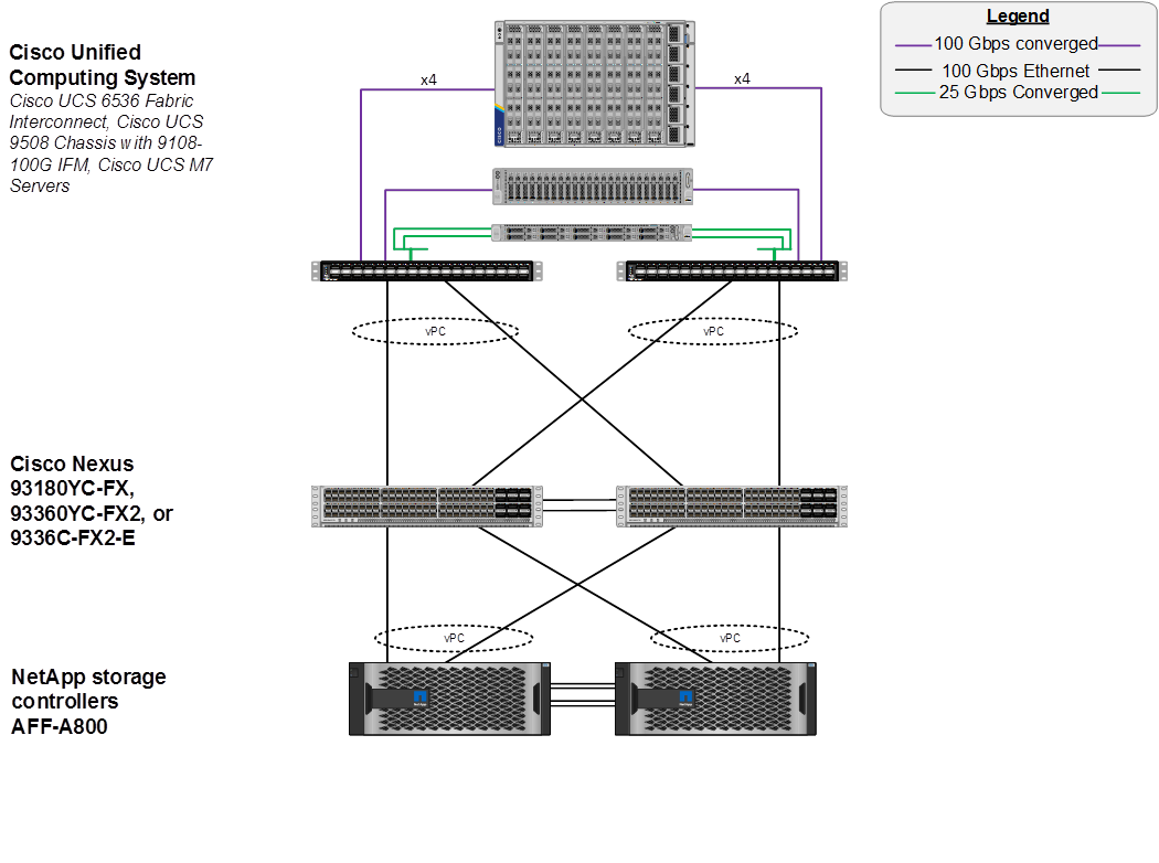
To validate the IP-based storage access in a FlexPod configuration, the components are set up as follows:
· Cisco UCS 6536 Fabric Interconnects provide the chassis and network connectivity.
· The Cisco UCS X9508 Chassis connects to fabric interconnects using Cisco UCSX-I-9108-100G intelligent fabric modules (IFMs), where four 100 Gigabit Ethernet ports are used on each IFM to connect to the appropriate FI. If additional bandwidth is required, all eight 100G ports can be utilized. The Cisco UCSX-I-9108-25G IFMs can also be used with 4x25G breakout cables used to connect the chassis to the fabric interconnects.
· Cisco UCSX-210c M7 Compute Nodes contain fifth-generation Cisco 15231 virtual interface cards (VICs) which can be used with either IFM. Cisco 15420 and 15422 VICs can also be used with either IFM.
· Cisco UCS C220 or C240 M7 Servers contain either fifth-generation 15238 or 15428 VICs and connect to the fabric interconnects with either 100GE or 25GE (utilizing breakouts).
· The Cisco UCS 5108 Chassis with Cisco UCS B-Series servers can also be connected with 4x25G or 4x10G breakout cables.
· Cisco Nexus 93360YC-FX2 Switches in Cisco NX-OS mode provide the switching fabric.
· Cisco UCS 6536 Fabric Interconnect 100-Gigabit Ethernet uplink ports connect to Cisco Nexus 93360YC-FX2 Switches in a Virtual Port Channel (vPC) configuration.
· The NetApp AFF A800 controllers connect to the Cisco Nexus 93360YC-FX2 Switches using two 100 GE ports from each controller configured as a vPC.
· VMware 8.0 ESXi software is installed on Cisco UCS M7 Compute Nodes and servers to validate the infrastructure.
FC-based Storage Access: FC, FC-NVMe, and NFS
The physical topology for the FC-booted FlexPod Datacenter is shown in Figure 31.
Figure 31. FlexPod Datacenter Physical Topology for FC, FC-NVMe, and NFS
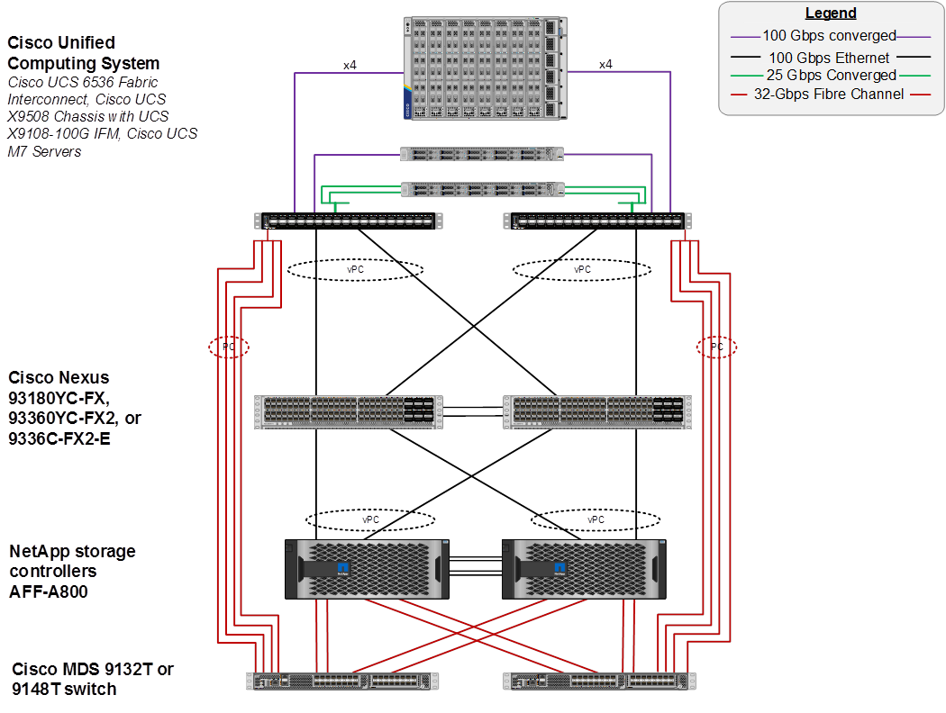
To validate the FC-based storage access in a FlexPod configuration, the components are set up as follows:
· Cisco UCS 6536 Fabric Interconnects provide the chassis and network connectivity.
· The Cisco UCS X9508 Chassis connects to fabric interconnects using Cisco UCSX 9108-100G Intelligent Fabric Modules (IFMs), where four 100 Gigabit Ethernet ports are used on each IFM to connect to the appropriate FI. If additional bandwidth is required, all eight 100G ports can be utilized. The Cisco UCSX-I-9108-25G IFMs can also be used with 4x25G breakout cables used to connect the chassis to the fabric interconnects.
· Cisco UCSX-210c M7 Compute Nodes contain fifth-generation Cisco UCS 15231 virtual interface cards (VICs) which can be used with either IFM. Cisco UCS 15420 and 15422 VICs can also be used with either IFM.
· Cisco UCS C220 or C240 M7 Servers contain either fifth-generation Cisco UCS 15238 or 15428 VICs and connect to the fabric interconnects with either 100GE or 25GE (utilizing breakouts).
· The Cisco UCS 5108 Chassis with Cisco UCS B-Series servers can also be connected with 4x25G or 4x10G breakout cables.
· Cisco Nexus 93360YC-FX2 Switches in Cisco NX-OS mode provide the switching fabric.
· Cisco UCS 6536 Fabric Interconnect 100 Gigabit Ethernet uplink ports connect to Cisco Nexus 93360YC-FX2 Switches in a vPC configuration.
· The NetApp AFF A800 controllers connect to the Cisco Nexus 93360YC-FX2 Switches using two 100 GE ports from each controller configured as a vPC for NFS traffic.
· Cisco UCS 6536 Fabric Interconnects are connected to the Cisco MDS 9132T switches using multiple 32-Gbps Fibre Channel connections (utilizing breakouts) configured as a single port channel for SAN connectivity.
· The NetApp AFF controllers connect to the Cisco MDS 9132T switches using 32-Gbps Fibre Channel connections for SAN connectivity.
· VMware 8.0 ESXi software is installed on Cisco UCS X210c M7 Compute Nodes and servers to validate the infrastructure.
FC-based Storage Access: FC, FC-NVMe, and NFS Utilizing Cisco Nexus SAN Switching
The physical topology for the FC-boot FlexPod Datacenter with Cisco Nexus SAN Switching is shown in Figure 32.
Figure 32. FlexPod Datacenter Physical Topology for FC, FC-NVMe, and NFS Utilizing Nexus SAN Switching
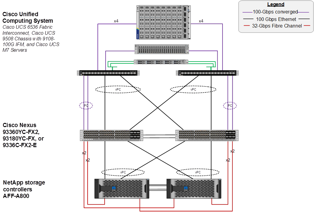
To validate the FC-based storage access in a FlexPod configuration with Cisco Nexus SAN switching, the components are set up as follows:
· Cisco UCS 6536 Fabric Interconnects provide the chassis and network connectivity.
· The Cisco UCS X9508 Chassis connects to fabric interconnects using Cisco UCSX 9108-100G Intelligent Fabric Modules (IFMs), where four 100 Gigabit Ethernet ports are used on each IFM to connect to the appropriate FI. If additional bandwidth is required, all eight 100G ports can be utilized. The Cisco UCSX-I-9108-25G IFMs can also be used with 4x25G breakout cables used to connect the chassis to the fabric interconnects.
· Cisco UCSX-210c M7 Compute Nodes contain fifth-generation Cisco UCS 15231 virtual interface cards (VICs) which can be used with either IFM. Cisco UCS 15420 and 15422 VICs can also be used with either IFM.
· Cisco UCS C220 or C240 M7 Servers contain either fifth-generation Cisco UCS 15238 or 15428 VICs and connect to the fabric interconnects with either 100GE or 25GE (utilizing breakouts).
· The Cisco UCS 5108 Chassis with Cisco UCS B-Series servers can also be connected with 4x25G or 4x10G breakout cables.
· Cisco Nexus 93360YC-FX2 Switches in Cisco NX-OS mode provide both the switching fabric and the SAN fabric.
· Cisco UCS 6536 Fabric Interconnect 100 Gigabit Ethernet uplink ports connect to Cisco Nexus 93360YC-FX2 Switches in a vPC configuration.
· The NetApp AFF A800 controller connects to the Cisco Nexus 93360YC-FX2 switches using two 100 GE ports from each controller configured as a vPC for NFS traffic.
· Cisco UCS 6536 Fabric Interconnects are connected to the Cisco Nexus 93360YC-FX2 switches using multiple 100-Gbps FCoE uplinks configured as a single Ethernet port channel.
· The NetApp AFF controllers connect to the Cisco Nexus 93360YC-FX2 switches using 32-Gbps Fibre Channel connections for SAN connectivity.
· VMware 8.0 ESXi software is installed on Cisco UCS X210c M7 Compute Nodes and servers to validate the infrastructure.
FC and IP-based Storage Access: FC, FC-NVMe, iSCSI, NVMe-TCP and NFS Utilizing Direct Attached Storage
The physical topology for the FlexPod Datacenter with Direct Attached Storage is shown in Figure 33.
Figure 33. FlexPod Datacenter Physical Topology for FC, FC-NVMe, and NFS Utilizing Nexus SAN Switching
To validate the storage access in a FlexPod configuration with direct attached storage, the components are set up as follows:
· Cisco UCS 6536 Fabric Interconnects provide the chassis, network, and storage connectivity.
· The Cisco UCS X9508 Chassis connects to fabric interconnects using Cisco UCSX 9108-100G Intelligent Fabric Modules (IFMs), where four 100 Gigabit Ethernet ports are used on each IFM to connect to the appropriate FI. If additional bandwidth is required, all eight 100G ports can be utilized. The Cisco UCSX-I-9108-25G IFMs can also be used with 4x25G breakout cables used to connect the chassis to the fabric interconnects.
· Cisco UCSX-210c M7 Compute Nodes contain fifth-generation Cisco UCS 15231 virtual interface cards (VICs) which can be used with either IFM. Cisco UCS 15420 and 15422 VICs can also be used with either IFM.
· Cisco UCS C220 or C240 M7 Servers contain either fifth-generation Cisco UCS 15238 or 15428 VICs and connect to the fabric interconnects with either 100GE or 25GE (utilizing breakouts).
· The Cisco UCS 5108 Chassis with Cisco UCS B-Series servers can also be connected with 4x25G or 4x10G breakout cables.
· Cisco Nexus 93360YC-FX2 Switches in Cisco NX-OS mode provide the switching uplink for the FIs out of the FlexPod.
· Cisco UCS 6536 Fabric Interconnect 100 Gigabit Ethernet uplink ports connect to Cisco Nexus 93360YC-FX2 Switches in a vPC configuration.
· The NetApp AFF A800 controller Ethernet ports connect to the Cisco UCS 6536 FIs using two 100 GE appliance ports from each controller configured as individual ports for NFS and optional iSCSI, NVMe-TCP traffic.
· The NetApp AFF A800 controller 32G FC ports connect to the Cisco UCS 6536 FI fc storage ports using up to four fc ports from each controller for optional FC and FC-NVMe traffic. Fibre Channel zoning for storage boot targets is automatically done in the FIs. Additional zoning for additional targets, targets in different SVMs, and FC-NVMe targets is done by IMM policy applied to the servers and the FIs. Zoning can also be done in upstream MDS or Nexus switches if FC or FCoE uplinks are connected as ISLs to those switches. Note that the FIs do not support either enhanced device alias or smart zoning and the upstream switching fabric would need to be configured without those features turned on for the required full zone distribution to take place.
· VMware 8.0 ESXi software is installed on Cisco UCS X210c M7 Compute Nodes and servers to validate the infrastructure.
VLAN Configuration
Table 1 lists VLANs configured for setting up the FlexPod environment along with their usage.
| VLAN ID |
Name |
Usage |
| 2 |
Native-VLAN |
Use VLAN 2 as native VLAN instead of default VLAN (1) |
| 1020 |
OOB-MGMT-VLAN |
Out-of-band management VLAN to connect management ports for various devices |
| 1021 |
IB-MGMT-VLAN |
In-band management VLAN utilized for all in-band management connectivity - for example, ESXi hosts, VM management, and so on. |
| 1022 |
VM-Traffic |
VM data traffic VLAN |
| 3050 |
NFS-VLAN |
NFS VLAN for mounting datastores in ESXi servers for VMs |
| 3010* |
iSCSI-A |
iSCSI-A path for boot-from-san traffic |
| 3020* |
iSCSI-B |
iSCSI-B path for boot-from-san traffic |
| 3030* |
NVMe-TCP-A |
NVMe-TCP-A path for NVMe datastores |
| 3040* |
NVMe-TCP-B |
NVMe-TCP-B path for NVMe datastores |
| 3000 |
vMotion |
VMware vMotion traffic |
* iSCSI and NVMe-TCP VLANs are not required if using FC storage access.
Some of the key highlights of VLAN usage are as follows:
· VLAN 1020 allows you to manage and access out-of-band management interfaces of various devices and is brought into the infrastructure to allow CIMC access to the Cisco UCS servers and is also available to infrastructure virtual machines (VMs). Interfaces in this VLAN are configured with MTU 1500.
· VLAN 1021 is used for in-band management of VMs, ESXi hosts, and other infrastructure services. Interfaces in this VLAN are configured with MTU 1500.
· VLAN 3050 provides ESXi hosts access to the NFS datastores hosted on the NetApp Controllers for deploying VMs. Interfaces in this VLAN are configured with MTU 9000.
· A pair of iSCSI VLANs (3010 and 3020) is configured to provide access to boot LUNs for ESXi hosts and iSCSI datastores. These VLANs are not needed when configuring Fibre Channel connectivity. Interfaces in these VLANs are configured with MTU 9000.
· A pair of NVMe-TCP VLANs (3030 and 3040) is configured to provide access to NVMe datastores. These VLANs are not needed when configuring Fibre Channel connectivity. Interfaces in these VLANs are configured with MTU 9000.
In FlexPod Datacenter deployments, each Cisco UCS server equipped with a Cisco Virtual Interface Card (VIC) is configured for multiple virtual Network Interfaces (vNICs), which appear as standards-compliant PCIe endpoints to the OS. The end-to-end logical connectivity including VLAN/VSAN usage between the server profile for an ESXi host and the storage configuration on NetApp AFF A800 controllers is described below.
Logical Topology for IP-based Storage Access
Figure 34 illustrates the end-to-end connectivity design for IP-based storage access.
Figure 34. Logical End-to-End Connectivity for iSCSI Design
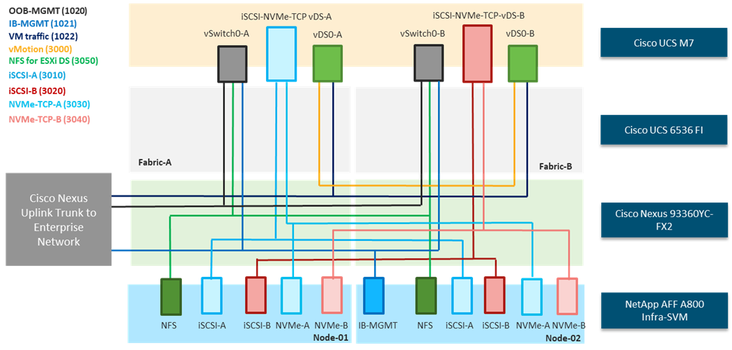
Each ESXi server profile supports:
· Managing the ESXi hosts using a common management segment.
· Diskless SAN boot using iSCSI with persistent operating system installation for true stateless computing.
· Six vNICs where:
° Two redundant vNICs (vSwitch0-A and vSwitch0-B) carry management and infrastructure NFS traffic. The MTU value for these vNICs is set as a Jumbo MTU (9000), but management interfaces with MTU 1500 can be placed on these vNICs.
° Two redundant vNICs (vDS0-A and vDS0-B) are used by the first vSphere Distributed switch (vDS) and carry VMware vMotion traffic and your application data traffic. The MTU for the vNICs is set to Jumbo MTU (9000), but interfaces that require MTU 1500 can be placed on these vNICs.
° Two vNICs (iSCSi/NVMe-TCP-A and iSCSi/NVMe-TCP-B) are used by the iSCSI-NVMe-TCP vDS. The iSCSI VLANs are set as native on the corresponding vNICs, and the NVMe-TCP VLANs are set as tagged VLANs on the corresponding vNICs. The MTU value for the vNICs and all interfaces on the vDS is set to Jumbo MTU (9000). The initial VMware ESXi setup utilizes two vSwitches, but the vNICs and VMkernel ports are migrated to the second vDS.
· Each ESXi host (compute node) mounts VM datastores from NetApp AFF A800 controllers using NFS for deploying virtual machines.
Logical Topology for FC-based Storage Access
Figure 35 illustrates the end-to-end connectivity design for FC-based storage access.
Figure 35. Logical End-to-End Connectivity for FC Design
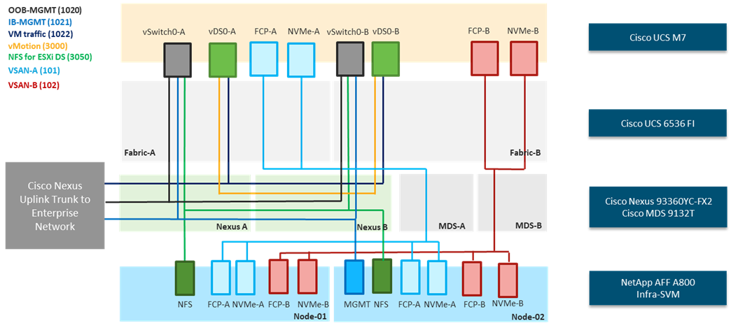
Each ESXi server profile supports:
· Managing the ESXi hosts using a common management segment.
· Diskless SAN boot using FC with persistent operating system installation for true stateless computing.
· Four vNICs where:
° Two redundant vNICs (vSwitch0-A and vSwitch0-B) carry management and Infrastructure NFS VLANs. The MTU value for these vNICs is set as a Jumbo MTU (9000), but management interfaces with MTU 1500 can be placed on these vNICs.
° Two redundant vNICs (vDS0-A and vDS0-B) are used by vDS0 and carry VMware vMotion traffic and your application data traffic. The MTU for the vNICs is set to Jumbo MTU (9000), but interfaces that require MTU 1500 can be placed on these vNICs.
° Two vHBAs (one for FC and one for FC-NVMe) defined on Fabric A to provide access to SAN-A path.
° Two vHBAs (one for FC and one for FC-NVMe) defined on Fabric B to provide access to SAN-B path.
· Each ESXi host (compute node) mounts VM datastores from NetApp AFF A800 controllers using NFS for deploying virtual machines.
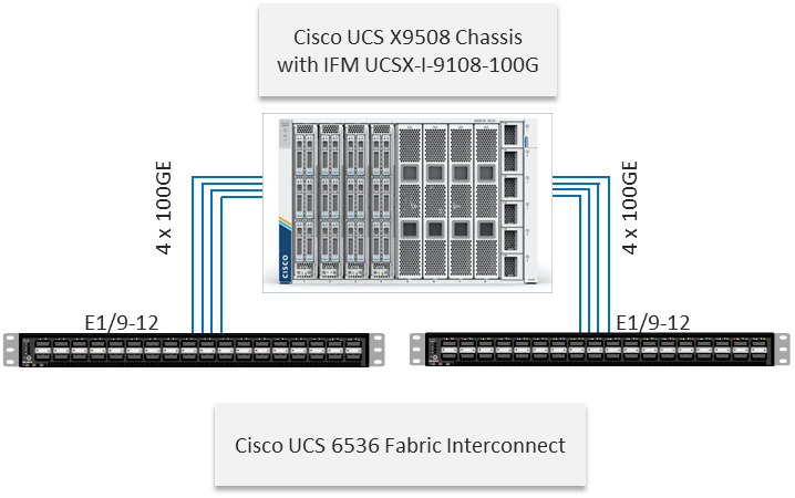
The Cisco UCS X9508 Chassis is equipped with the Cisco UCS 9108-100G intelligent fabric modules (IFMs). The Cisco UCS X9508 Chassis connects to each Cisco UCS 6536 FI using four 100GE ports, as shown in Figure 36. If the you require more bandwidth, all eight ports on the IFMs can be connected to each FI.
Figure 36. Cisco UCS X9508 Chassis Connectivity to Cisco UCS Fabric Interconnects
Cisco Nexus Ethernet Connectivity
The Cisco Nexus 93360YC-FX2 device configuration explains the core networking requirements for Layer 2 and Layer 3 communication. Some of the key NX-OS features implemented within the design are:
· Feature interface-vans—Allows for VLAN IP interfaces to be configured within the switch as gateways.
· Feature HSRP—Allows for Hot Standby Routing Protocol configuration for high availability.
· Feature LACP—Allows for the utilization of Link Aggregation Control Protocol (802.3ad) by the port channels configured on the switch.
· Feature VPC—Virtual Port-Channel (vPC) presents the two Nexus switches as a single “logical” port channel to the connecting upstream or downstream device.
· Feature LLDP—Link Layer Discovery Protocol (LLDP), a vendor-neutral device discovery protocol, allows the discovery of both Cisco devices and devices from other sources.
· Feature NX-API—NX-API improves the accessibility of CLI by making it available outside of the switch by using HTTP/HTTPS. This feature helps with configuring the Cisco Nexus switch remotely using the automation framework.
· Feature UDLD—Enables unidirectional link detection for various interfaces.
Cisco UCS Fabric Interconnect 6536 Ethernet Connectivity
Cisco UCS 6536 FIs are connected with port channels to Cisco Nexus 93360YC-FX2 switches using 100GE connections configured as virtual port channels. Each FI is connected to both Cisco Nexus switches using a 100G connection; additional links can easily be added to the port channel to increase the bandwidth as needed. Figure 37 illustrates the physical connectivity details.
Figure 37. Cisco UCS 6536 FI Ethernet Connectivity
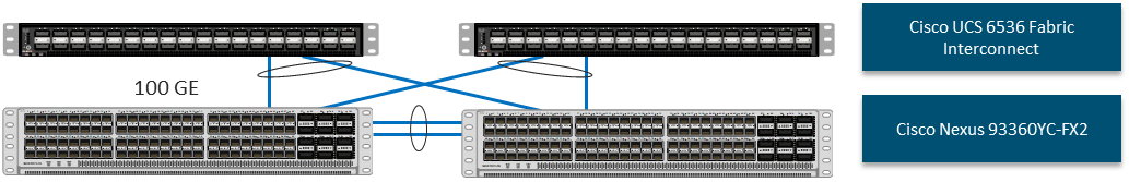
NetApp AFF A800 Ethernet Connectivity
NetApp AFF A800 controllers are connected with port channels (NetApp Interface Groups) to Cisco Nexus 93360YC-FX2 switches using 100GE connections configured as virtual port channels. The storage controllers are deployed in a switchless cluster interconnect configuration and are connected to each other using the 100GE ports e0a and e1a. Figure 38 illustrates the physical connectivity details.
In Figure 38, the two storage controllers in the high-availability pair are drawn separately for clarity. Physically, the two controllers exist within a single chassis.
Figure 38. NetApp AFF A800 Ethernet Connectivity
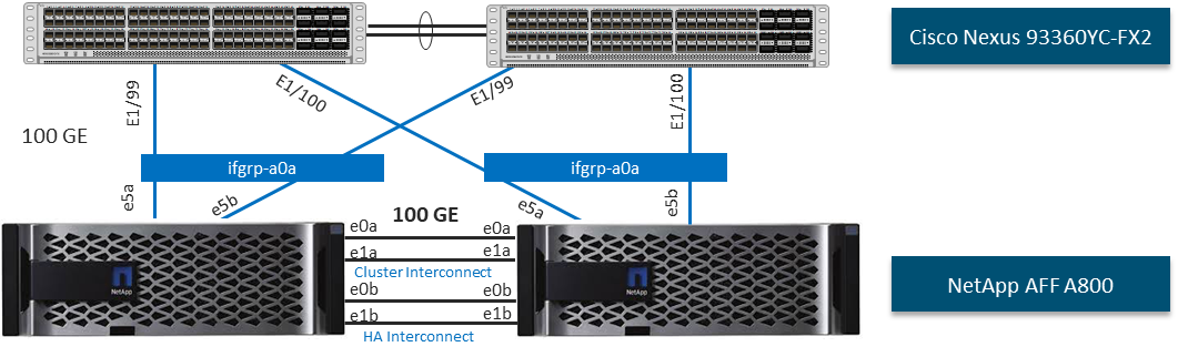
Cisco MDS SAN Connectivity – Fibre Channel Design Only
The Cisco MDS 9132T is the key design component bringing together the 32Gbps Fibre Channel (FC) capabilities to the FlexPod design. A redundant 32 Gbps Fibre Channel SAN configuration is deployed utilizing two Cisco MDS 9132Ts switches. Some of the key MDS features implemented within the design are:
· Feature NPIV—N port identifier virtualization (NPIV) provides a means to assign multiple FC IDs to a single N port.
· Feature fport-channel-trunk—F-port-channel-trunks allow for the fabric logins from the NPV switch to be virtualized over the port channel. This provides nondisruptive redundancy should individual member links fail.
· Enhanced Device Alias – a feature that allows device aliases (a name for a WWPN) to be used in zones instead of WWPNs, making zones more readable. Also, if a WWPN for a vHBA or NetApp FC LIF changes, the device alias can be changed, and this change will carry over into all zones that use the device alias instead of changing WWPNs in all zones.
· Smart-Zoning—a feature that reduces the number of TCAM entries and administrative overhead by identifying the initiators and targets in the environment.
Cisco UCS Fabric Interconnect 6536 SAN Connectivity
For SAN connectivity, each Cisco UCS 6536 Fabric Interconnect in FC end host or NPV mode is connected to a Cisco MDS 9132T SAN switch using at least one breakout on ports 33-36 to a 4 x 32G Fibre Channel port-channel connection, as shown in Figure 39.
Figure 39. Cisco UCS 6536 FI SAN Connectivity
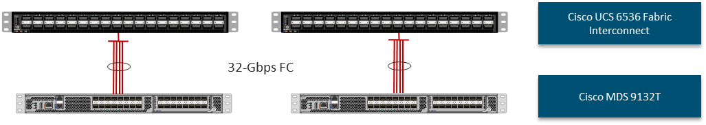
NetApp AFF A800 SAN Connectivity
For SAN connectivity, each NetApp AFF A800 controller is connected to both of Cisco MDS 9132T SAN switches using 32G Fibre Channel connections, as shown in Figure 40. FC-NVMe LIFs can be put on the same FC ports on the NetApp storage controllers as FC LIFs.
In Figure 40, the two storage controllers in the high-availability pair are drawn separately for clarity. Physically, the two controllers exist within a single chassis.
Figure 40. NetApp AFF A800 SAN Connectivity
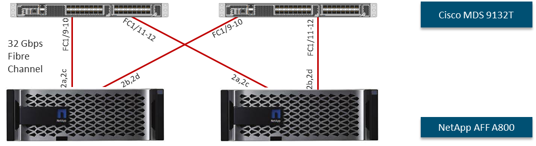
Cisco UCS Configuration – Cisco Intersight Managed Mode
Cisco Intersight Managed Mode standardizes policy and operation management for Cisco UCS X-Series and the remaining Cisco UCS hardware used in this CVD. The Cisco UCS compute nodes and servers are configured using server profiles defined in Cisco Intersight. These server profiles derive all the server characteristics from various policies and templates. At a high level, configuring Cisco UCS using Intersight Managed Mode consists of the steps shown in Figure 41.
Figure 41. Configuration Steps for Cisco Intersight Managed Mode
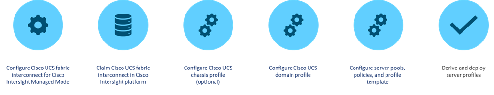
Set up Cisco UCS Fabric Interconnect for Cisco Intersight Managed Mode
During the initial configuration, for the management mode the configuration wizard enables you to choose whether to manage the fabric interconnect through Cisco UCS Manager or the Cisco Intersight platform. You can switch the management mode for the fabric interconnects between Cisco Intersight and Cisco UCS Manager at any time; however, Cisco UCS FIs must be set up in Intersight Managed Mode (IMM) for configuring the Cisco UCS X-Series system and the Cisco UCS 6536 fabric interconnects. Figure 42 shows the dialog during initial configuration of Cisco UCS FIs for setting up IMM.
Figure 42. Fabric Interconnect Setup for Cisco Intersight Managed Mode
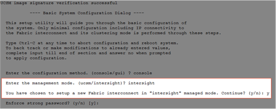
Claim a Cisco UCS Fabric Interconnect in the Cisco Intersight Platform
After setting up the Cisco UCS Fabric Interconnect for Cisco Intersight Managed Mode, FIs can be claimed to a new or an existing Cisco Intersight account. When a Cisco UCS fabric interconnect is successfully added to the Cisco Intersight platform, all future configuration steps are completed in the Cisco Intersight portal.
Figure 43. Cisco Intersight: Fabric Interconnects
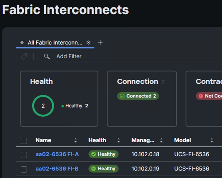
You can verify whether a Cisco UCS Fabric Interconnect is in Cisco UCS Manager managed mode or Cisco Intersight Managed Mode by clicking on the fabric interconnect name and looking at the detailed information screen for the FI, as shown in Figure 44.
Figure 44. Cisco UCS FI in Intersight Managed Mode
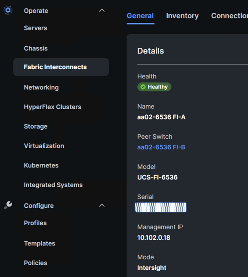
Cisco UCS Chassis Profile
A Cisco UCS Chassis profile configures and associates chassis policy to an IMM claimed chassis. The chassis profile feature is available in Intersight with the Intersight Essentials License. The chassis-related policies can be attached to the profile either at the time of creation or later.
The chassis profile in a FlexPod is used to set the power and thermal policies for the chassis. By default, Cisco UCSX power supplies are configured in GRID mode, but the power policy can be utilized to set the power supplies in non-redundant or N+1/N+2 redundant modes. The default thermal policy configures the chassis fans in the Balanced mode. Optional settings for the thermal policy are Low Power, High Power, Maximum Power, and Acoustic. The Cisco UCS Chassis profile is being configured in this CVD with the default power and thermal policies to give you a starting point for optimizing chassis power usage.
Cisco UCS Domain Profile
A Cisco UCS domain profile configures a fabric interconnect pair through reusable policies, allows configuration of the ports and port channels, and configures the VLANs and VSANs to be used in the network. It defines the characteristics of and configures the ports on the fabric interconnects. One Cisco UCS domain profile can be assigned to one fabric interconnect domain, and the Cisco Intersight platform supports the attachment of one port policy per Cisco UCS fabric interconnect.
Some of the characteristics of the Cisco UCS domain profile in the FlexPod environment are:
· A single domain profile is created for the pair of Cisco UCS fabric interconnects.
· Unique port policies are defined for each of the two fabric interconnects.
· The VLAN configuration policy is common to the fabric interconnect pair because both fabric interconnects are configured for the same set of VLANs.
· The VSAN configuration policies (FC connectivity option) are unique for the two fabric interconnects because the VSANs are unique.
· The Network Time Protocol (NTP), network connectivity, Link Control (UDLD), SNMP, and system Quality-of-Service (QoS) policies are common to the fabric interconnect pair.
After the Cisco UCS domain profile has been successfully created and deployed, the policies including the port policies are pushed to the Cisco UCS fabric interconnects. The Cisco UCS domain profile can easily be cloned to install additional Cisco UCS systems. When cloning the Cisco UCS domain profile, the new Cisco UCS domains utilize the existing policies for consistent deployment of additional Cisco UCS systems at scale.
Figure 45. Cisco UCS Domain Profile
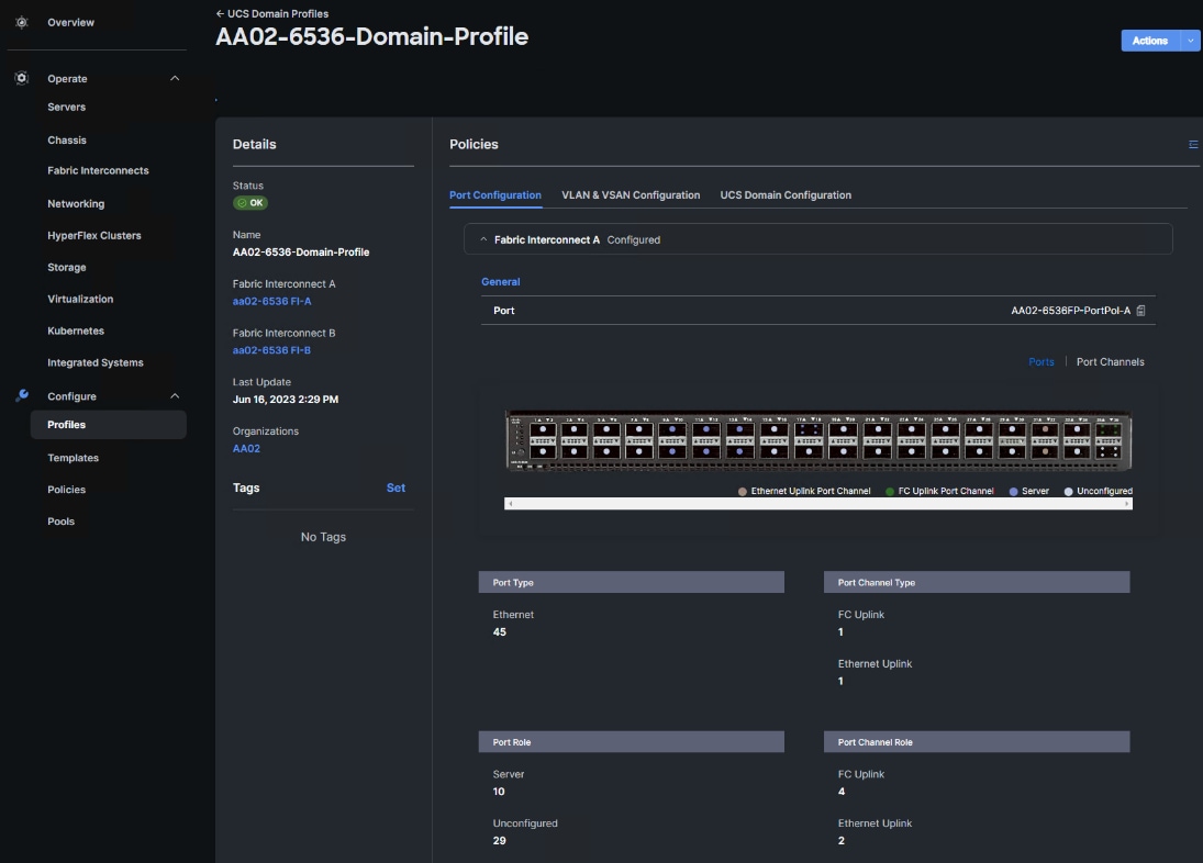
The Cisco UCS X9508 Chassis, Cisco UCS X210c M7 Compute Nodes and C220 or C240 M7 servers are automatically discovered when the ports are successfully configured using the domain profile as shown in Figures 46 through 50.
Figure 46. Cisco UCS X9508 Chassis Front View
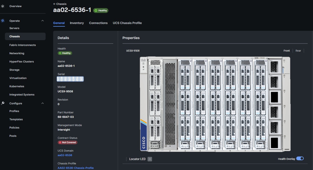
Figure 47. Cisco UCS X9508 Chassis Rear View
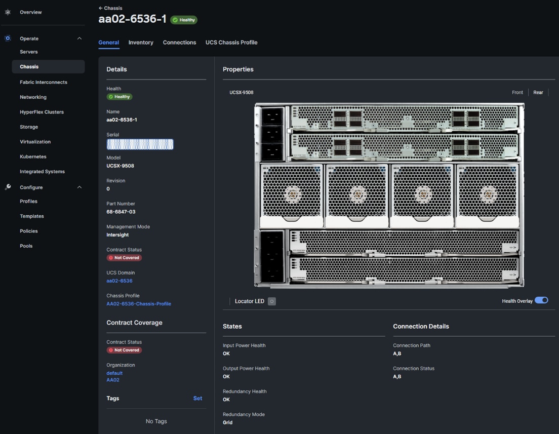
Figure 48. Cisco UCS X210c M7 Compute Nodes
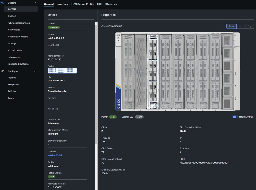
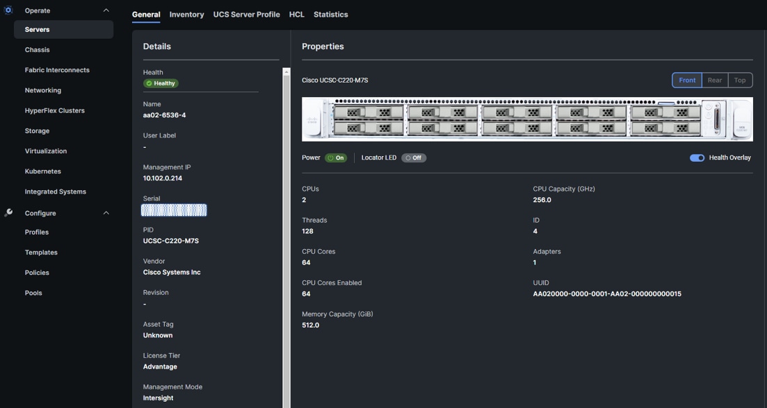
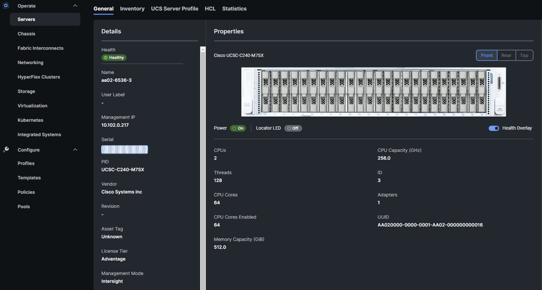
Server Profile Template
A server profile template enables resource management by simplifying policy alignment and server configuration. A server profile template is created using the server profile template wizard. The server profile template wizard groups the server policies into the following four categories to provide a quick summary view of the policies that are attached to a profile:
· Compute policies: BIOS, boot order, power (Cisco UCS X- and Cisco UCS B-Series servers only), and UUID pool.
· Network policies: adapter configuration, LAN connectivity, and SAN connectivity policies.
° The LAN connectivity policy requires you to create the Ethernet network policy, Ethernet adapter policy, and Ethernet QoS policy.
° The SAN connectivity policy requires you to create the Fibre Channel (FC) network policy, Fibre Channel adapter policy, Fibre Channel QoS policy, and optional FC zoning policy used with direct attached storage. The SAN connectivity policy is only required for the FC connectivity option.
· Storage policies: not used in FlexPod.
· Management policies: Integrated Management Controller (IMC) Access, Intelligent Platform Management Interface (IPMI) over LAN, local user, Serial over LAN (SOL), Simple Network Management Protocol (SNMP), syslog, and virtual Keyboard, Video, and Mouse (KVM) policies.
Some of the characteristics of the server profile template for FlexPod are as follows:
· The BIOS policy is created to specify various server parameters in accordance with FlexPod best practices and Cisco UCS Performance Tuning Guides.
· The Boot order policy defines virtual media (KVM mapped DVD), all SAN paths for NetApp iSCSI or Fibre Channel logical interfaces (LIFs), and a CIMC mapped DVD for OS installation.
· The IMC access policy defines the management IP address pool for KVM access.
· The Local user policy is used to enable KVM-based user access.
· For the iSCSI boot from SAN configuration, the LAN connectivity policy is used to create six virtual network interface cards (vNICs); two for the management virtual switch (vSwitch0), two for the application Virtual Distributed Switch (vDS), and two for the iSCSI-NVMe-TCP vDS. Various policies and pools are also created for the vNIC configuration.
· For the FC boot from SAN configuration, the LAN connectivity policy is used to create four virtual network interface cards (vNICs); two for the management virtual switch (vSwitch0) and two for the application Virtual Distributed Switch (vDS); along with various policies and pools.
· For the FC boot and connectivity option, the SAN connectivity policy is used to create four virtual host bus adapters (vHBAs); two each (FC and FC-NVMe) for SAN A and for SAN B; along with various policies and pools. The SAN connectivity policy is not required for iSCSI boot setup.
Figure 51 shows various policies associated with a server profile template.
Figure 51. Server Profile Template for FC Boot from SAN
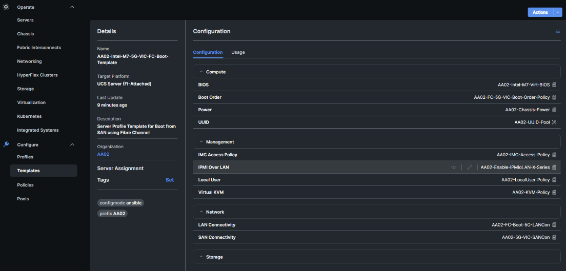
Derive and Deploy Server Profiles from the Cisco Intersight Server Profile Template
The Cisco Intersight server profile allows server configurations to be deployed directly on the compute nodes based on polices defined in the server profile template. After a server profile template has been successfully created, server profiles can be derived from the template and associated with the Cisco UCS Compute Nodes, as shown in Figure 52.
Figure 52. Deriving a Server Profile from Templates
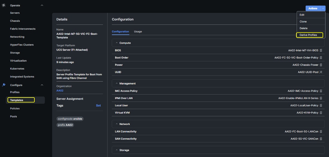
On successful deployment of the server profile, the Cisco UCS Compute Nodes are configured with parameters defined in the server profile and can boot from the storage LUN hosted on the NetApp AFF system.
Cisco UCS Ethernet Adapter Policies
One point of optimization with Cisco UCS in FlexPod is use of Cisco UCS Ethernet Adapter policies to optimize network traffic into multiple receive (RX) queues to maximize the use of multiple CPU cores in servicing these queues resulting in higher network throughput on up to 100Gbps interfaces. IMM (and UCSM) adapter policies allow the number of transmit (TX) and RX queues and the queue ring size (buffer size) to be adjusted, and features such as Receive Side Scaling (RSS) to be enabled. RSS allows multiple RX queues to each be assigned to a different CPU core, allowing parallel processing of incoming Ethernet traffic. VMware ESXi 8.0 supports RSS, a single TX queue, and up to 16 RX queues. This CVD utilizes the fifth-generation Cisco UCS VICs which support a ring size up to 16K (16,384), where the previous fourth-generation VICs support a ring size up to 4K (4096). Increasing the ring size can result in increased latency, but with the higher speed 100Gbps interfaces used in this CVD, the data moves through the buffers in less time, minimizing the latency increase. In this CVD, up to four Ethernet Adapter policies are defined:
| Policy Name |
TX Queues |
TX Ring Size |
RX Queues |
RX Ring Size |
RSS |
| VMware-Default |
1 |
256 |
1 |
512 |
Disabled |
| VMware-High Traffic |
1 |
4096 |
8 |
4096 |
Enabled |
| VMware-4G-16RXQs |
1 |
4096 |
16 |
4096 |
Enabled |
| VMware-5G-16RXQs |
1 |
16384 |
16 |
16384 |
Enabled |
Figure 53 shows part of the VMware-5G-16RXQs Ethernet Adapter policy in Cisco Intersight. Notice that not only the fields in the above table have been modified, but also Completion Queue Count (TX Queues + RX Queues) and Interrupts (Completion Queue Count + 2) have also been modified. For more information on configuring Ethernet Adapter polices, go to: https://www.cisco.com/c/en/us/products/collateral/interfaces-modules/unified-computing-system-adapters/white-paper-c11-744754.html.
Figure 53. VMware-5G-16Rx Ethernet Adapter Policy
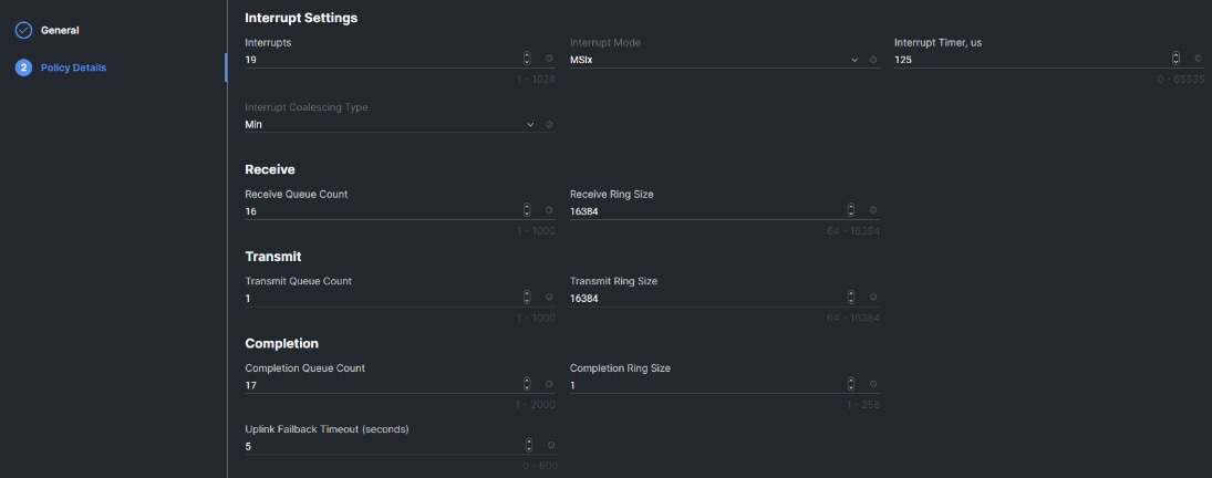
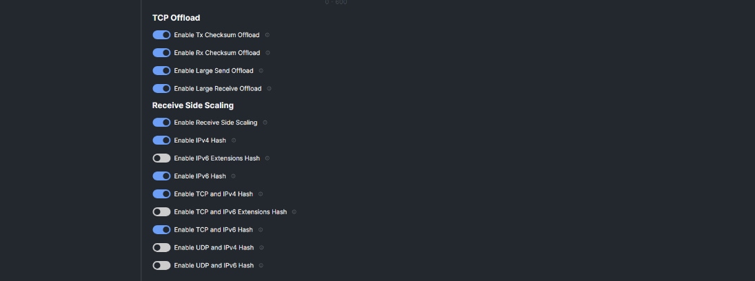
Cisco UCS Fibre Channel Adapter Policy for FC-NVMe
Another point of optimization with Cisco UCS in FlexPod is use of a Cisco UCS Fibre Channel Adapter policy optimized for FC-NVMe. This policy utilizes 16 SCSI I/O queues (the standard VMware Fibre Channel Adapter Policy for FC uses one SCSI I/O queue) to provide a similar optimization of multiple CPU cores servicing multiple queues that you can get with the Ethernet Adapter Policies.
Figure 54. FC-NVMe-Initiator Adapter Policy
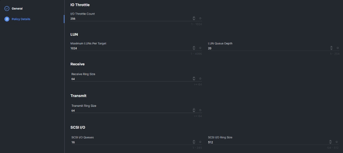
Cisco Intersight-Managed Operating System (OS) Installation
Cisco Intersight enables you to install vMedia-based operating systems managed servers in a data center. With this capability, you can perform an unattended OS installation on one or more Cisco Intersight Managed Mode (IMM) servers (Cisco UCS C-Series, B-Series, and X-Series) or Cisco UCS C-Series Standalone servers from your centralized data center through a simple process. Intersight-Managed OS installation is now supported with iSCSI or FC SAN Boot for all Cisco UCS M7 servers and for VMware ESXi 8.0, including using the Cisco Custom ISO for VMware ESXi 8.0. The end result of this install is a SAN-booted server with an assigned IP address on VMware VMkernel port 0 (vmk0). This feature requires the Intersight Advantage license and is used in the deployment guides.
NetApp AFF – Storage Virtual Machine (SVM) Design
To provide the necessary data segregation and management, a dedicated SVM (Infra-SVM) is created for hosting the VMware environment. The SVM contains the following volumes and logical interfaces (LIFs):
· Volumes
° ESXi boot volume (esxi_boot) that consists of ESXi boot LUNs, used to enable ESXi host boot using iSCSI or FC boot from SAN. The boot LUNs are 128GB in size and thin provisioned as per VMware recommendation.
° Infrastructure datastores used by the vSphere environment to store the VMs and swap files. Separate datastores to be configured for NFS volume and NVMe namespace. The datastore configured for NVMe may be used for NVMe-TCP or FC-NVMe.
° Datastore used by the vSphere environment to host vSphere Cluster Services (vCLS) VMs. By default, the datastore placement logic chooses an available datastore hence it is recommended to create a dedicated datastore for vCLS VMs.
Note: It is a NetApp best practice to create Load sharing mirror for each SVM root volume that serves NAS data in the cluster. For more information on LSM, go to: https://docs.netapp.com/us-en/ontap/data-protection/manage-snapmirror-root-volume-replication-concept.html
· Logical interfaces (LIFs)
° NFS LIFs to mount NFS datastores in the vSphere environment
° NVMe-TCP LIFs to connect to NVMe namespace from VMs using NVMe over TCP
° iSCSI A/B LIFs or FC LIFs to connect to ESXi boot LUNs or application data using iSCSI and FC Protocol
° FC-NVMe LIFs for VMs to connect to NVMe datastores using NVMe over FC traffic
Each LIF belongs to specific VLANs or VSANs assigned for that traffic, as described earlier in this document. For IP based LIFs, IP addresses are assigned from subnets assigned to the respective VLAN. The IP based LIFs configured for SAN storage (iSCSI, FC-NVMe, NVMe-TCP) require 2 IP addresses per controller to allow all 4 paths between the end host and storage. LIFs configured for NFS requires one IP address per controller.
A visual representation of volumes and logical interfaces (LIFs) are shown in Figure 55 and Figure 56, for iSCSI and FC boot.
Figure 55. NetApp AFF A800 - Infra-SVM for iSCSI Boot
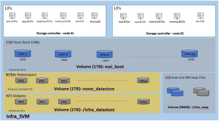
Figure 56. NetApp AFF A800 – Infra-SVM for FC Boot
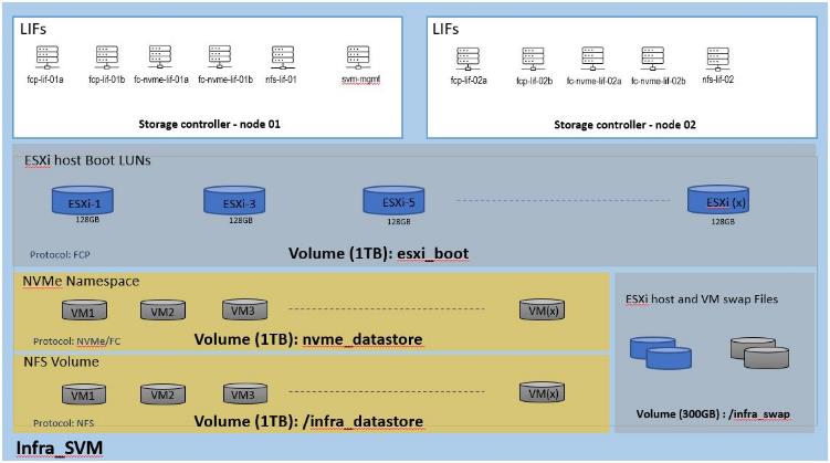
Multiple vNICs (and vHBAs) are created for the ESXi hosts using the Cisco Intersight server profile and are then assigned to specific virtual and distributed switches. The vNIC and (optional) vHBA distribution for the ESXi hosts is as follows:
· Two vNICs (one on each fabric) for vSwitch0 to support core services such as management and infrastructure NFS traffic. The standard VMware-Default Cisco UCS Ethernet adapter policy is assigned to these vNICs.
· Two vNICs (one on each fabric) for a vSphere Virtual Distributed Switch (vDS0) to support your or tenant data traffic and vMotion traffic. In this vDS, vMotion is pinned to Cisco UCS Fabric B so that vMotion is switched in the B-side fabric interconnect. A maximum performance VMware-5G-16RXQs or VMware-4G-16RXQs Cisco UCS Ethernet adapter policy utilizing receive side scaling (RSS) is assigned to these vNICs. If higher performance for infrastructure NFS is desired, the NFS VMkernel ports can be migrated to this vDS, provided the infrastructure NFS VLAN is configured in the Ethernet network group policy for the vNICs on this vDS.
· Two vNICs (one on each fabric) for the iSCSI-NVMe-TCP vSphere Virtual Distributed Switch (iSCSI-NVMe-TCP-vDS) to support iSCSI (including boot) and NVMe-TCP traffic. In this vDS, both the iSCSI and NVMe-TCP VMkernel ports are pinned to the appropriate fabric. A maximum performance VMware-5G-16RXQs or VMware-4G-16RXQs Cisco UCS Ethernet adapter policy, utilizing receive side scaling (RSS) and maximum buffer size is assigned to these vNICs.
Note: Typically, you will either have iSCSI vNICs or the FC vHBAs configured for stateless boot from SAN of the ESXi servers.
Figure 57 and Figure 58 show the ESXi vNIC configurations in detail.
Figure 57. VMware vSphere - ESXi Host Networking for iSCSI Boot from SAN

Figure 58. VMware vSphere - ESXi Host Networking for FC Boot from SAN
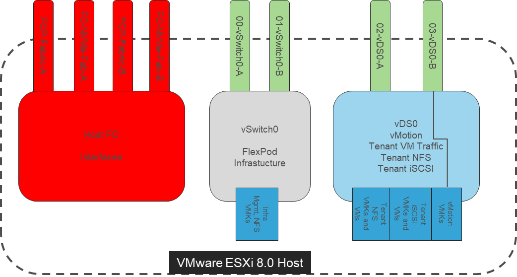
Cisco Intersight Integration with VMware vCenter, NetApp Storage, and Cisco Switches
Cisco Intersight works with NetApp’s ONTAP storage and VMware vCenter using third-party device connectors, and Cisco Nexus and MDS switches using a Cisco device connector. Since third-party infrastructure does not contain any built-in Intersight device connector, Cisco Intersight Assist virtual appliance enables Cisco Intersight to communicate with both non-Cisco devices and supported Cisco switches.
Note: A single Cisco Intersight Assist virtual appliance can support NetApp ONTAP storage, VMware vCenter, and Cisco switches.
Cisco Intersight integration with VMware vCenter, NetApp ONTAP, and Cisco switches enables you to perform the following tasks right from the Intersight dashboard:
· Monitor the virtualization, storage, and switching environment.
· Add various dashboard widgets to obtain useful at-a-glance information.
· Perform common Virtual Machine tasks such as power on/off, remote console and so on.
· Orchestrate virtual, storage, and switching, environment to perform common configuration tasks.
The following sections explain the details of these operations. Since Cisco Intersight is a SaaS platform, the monitoring and orchestration capabilities are constantly being added and delivered seamlessly from the cloud.
Figure 59. Managing NetApp and VMware vCenter through Cisco Intersight using Intersight Assist
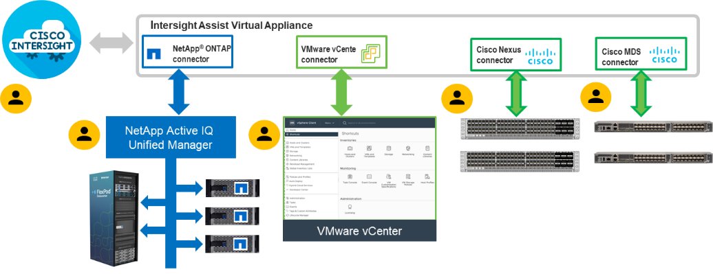
Licensing Requirement
To integrate and view various NetApp storage, VMware vCenter, and Cisco switch parameters from Cisco Intersight, a Cisco Intersight Advantage license is required. To use Cisco Intersight orchestration and workflows to provision the storage and virtual environments, an Intersight Advantage license is also required.
Integrate Cisco Intersight with NetApp ONTAP Storage
To integrate NetApp AFF A800 with Cisco Intersight, you need to deploy and configure:
· Cisco Intersight Assist virtual appliance
· NetApp Active IQ Unified Manager virtual appliance
Using the Cisco Intersight Assist, NetApp Active IQ Unified Manager (AIQUM) is claimed as a target in Cisco Intersight. When NetApp AIQUM is claimed, the NetApp storage clusters configured in AIQUM will appear in Intersight and can be monitored and orchestrated.
Obtain Storage-level Information
After successfully claiming the NetApp Active IQ Unified Manager as a target, you can view storage-level information in Cisco Intersight if they have already added NetApp AFF A800 to the NetApp Active IQ Unified Manager.
Figure 60. NetApp AFF A800 Information in Cisco Intersight
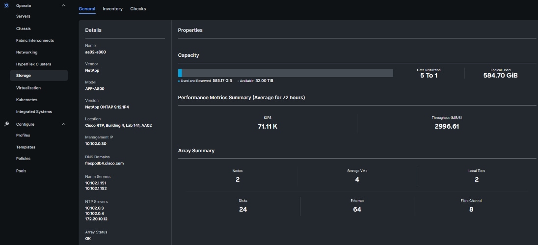
Integrate Cisco Intersight with VMware vCenter, Cisco Nexus Switches, and Cisco MDS Switches
To integrate VMware vCenter and supported Cisco switches with Cisco Intersight, you need use the deployed Cisco Intersight Assist virtual appliance. Using the Cisco Intersight Assist, VMware vCenter and supported Cisco switches are claimed as targets in Cisco Intersight.
Obtain VMware vCenter and Cisco Switch Information
After successfully claiming the VMware vCenter and supported Cisco switches as targets, you can view information on these products in Cisco Intersight.
Figure 61. VMware vCenter Information in Cisco Intersight
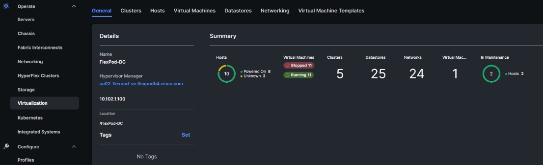
Figure 62. Cisco Nexus Information in Cisco Intersight
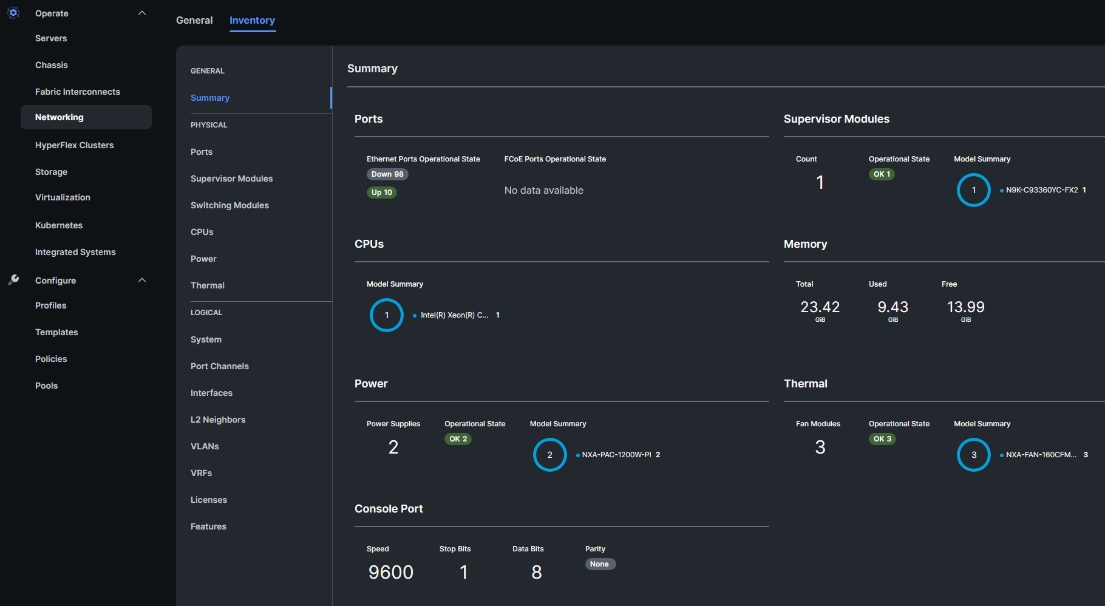
Figure 63. Cisco MDS Information (Tech Preview) in Cisco Intersight
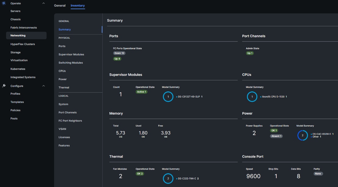
VMware vCenter Hardware Support Manager (HSM) Integration with Intersight
The Cisco Hardware Support Manager (HSM) service option enabled with vSphere Lifecycle Manager (vLCM) plug-in allows you to update the Operating System and perform firmware upgrades simultaneously with a single firmware image. You can enable HSM while claiming the VMware vCenter target in Cisco Intersight. You then configure a VMware ESXi cluster in vLCM to be managed with a single image. When composing the image, you select the ESXi Version – can range from the Cisco Custom ISO version to the latest version within the update release, the Vendor Addon downloaded from VMware.com – the additional drivers put into the Cisco Custom ISO, the Firmware and Drivers Addon – the server firmware version pulled from Cisco Intersight, and any additional components – VMware drivers updated since the release of the Cisco Custom ISO. Figure 64 shows an image setup for a cluster with Cisco UCS X210C M7 servers with the latest version of ESXi 8.0 at the time this document was written, the Cisco UCS Addon for VMware ESXi 8.0, UCS server firmware release 5.1(1.230052) and 3 additional components (2 disk controller drivers and the update Cisco UCS Tool component). The Image Compliance section shows that all servers in the cluster are running image compliant software and firmware.
To update any of the image components, you simply edit the image and select the updated component. This could be the ESXi version if a new version has been released or a new version of the server firmware. Once the updated image is saved, the Image Compliance will be check. If any servers are then out of compliance, they can be Remediated. The Remediation process will update the servers one at a time by putting them into Maintenance Mode and then proceeding with the update. If the update is a Cisco UCS firmware update, vCenter will signal the update with Cisco Intersight via the Intersight Assist VM, and Intersight will complete the server firmware update. The image can also be exported to either a JSON file to be imported as the image for another VMware ESXi cluster, as an ISO for installing directly onto ESXi hosts, or as a depot to be loaded into vCenter Image Builder.
Figure 64. VMware HSM Image with Latest VMware ESXi Update and Cisco UCS HCL Drivers
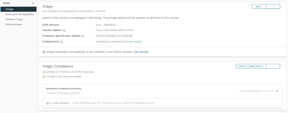
Data centers around the world currently account for approximately 1% of the global electricity consumption and 2% of the total within US, making them significant contributors to energy consumption. Among the various components within a data center, servers consume the largest share of the electricity. According to Gartner, the proportion of the overall data center power budget allocated to storage is expected to double by 2030, rising from less than 20% in 2020 to nearly 40%.
Figure 65. Power Distribution in IT Datacenters
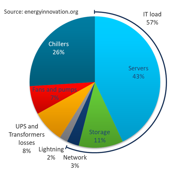
The compute and storage power consumption reflects the growing demand for servers and storage systems within data centers. As new applications and data continues to proliferate, the demand for the compute and storage capacity and performance is expected to rise. As environmental, social, and governance (ESG) issues become a corporate priority at all levels of organizations across the globe, so will the demand for efficient power consumption and sustainable energy across products and processes.
Organizations are actively seeking diverse strategies to minimize power consumption and achieve the sustainability targets that they have established for themselves. There are several approaches that can be taken to minimize power consumption and meet sustainability goals, some of which are outlined below.
Sustainable Design
One key approach is to focus on a modern, sustainable design while continuing efforts to reduce technical debt, and increase overall efficiency. Data center consolidation, modernization and maximizing rack utilization are crucial steps in this direction.
Replacing older servers with advanced models like the Cisco UCS M7 servers introduced in this solution can significantly improve performance and achieve higher virtual machine (VM) consolidation ratios compared to previous generations, while continuing to provide more flexibility and increased performance to support new and evolving applications. The Cisco UCS M7 servers can handle more workloads with a 4-to-1 consolidation ratio compared to previous generation servers.
The Cisco UCS X-9508 used in this solution, provides a future-ready platform with the density and efficiency of blade servers and the expandability and flexibility of rack servers. The modular, chassis-based design allows you to share resources (chassis enclosure, switching fabric, power, cooling) among multiple servers for a more efficient utilization of rack space, power, and cooling, while maintaining the flexibility to expand capabilities as needed. The 7-RU Cisco UCS-X9508 chassis supports up to 8 compute nodes with unified connectivity and management. Each compute node can also support up to 6 Solid-State Drives (SSDs), or Non-Volatile Memory Express (NVMe) drives for a total of ~90TB of local storage using 15.3TB NVMe drives available today. Local storage is listed here but is not typically used in FlexPod, where NetApp storage is used. For AI/ML, VDI and other compute-intensive workloads, you can add Nvidia and Intel Flex GPUs to the UCS X-series chassis, directly on each compute node or using a dedicated PCIe (X440p) node. Cisco UCS-X9508 can support up to 16 GPUs using the X440p PCIe nodes, with the option to add an additional two GPUs on the compute nodes. Cisco UCS X-Series is also designed for the next decade of computing, with the ability to support new technologies as they evolve and mature such as PCI Gen5.0, CXL and liquid cooling for a more efficient data center.
Sustainable Hardware
The NetApp ONTAP-based Storage Systems and Cisco UCS X-Series platform used in this solution are designed with sustainability in mind. This is a critical factor for Enterprises as they modernize their data centers and select infrastructure to consolidate their workloads on.
The Cisco UCS X-Series platform is designed with several energy efficient features to optimize power and cooling as outlined below. Cisco UCS X-Series was recently awarded the 2023 SEAL Sustainable Product Award for products that are “purpose-built” for a sustainable future.
· Cisco UCS X-Series chassis uses a more open design for less air impedance and minimal air-handling material to reduce the overall resources that need to be sourced and installed within the system.
· It is equipped with modular, titanium-rated power supply units (PSUs) and 54-volt DC-power delivery system that minimizes the many internal power conversions, internal copper cabling needed, and amperage – saving in both overhead and power loss.
· The Cisco UCS X-Series has modular counter-rotating fans with wider apertures and high cubic feet per minute (CFM). It also has innovative zone-based cooling to optimize only those components needing more handling. And with an innovative fan speed algorithm, an industry first, the Cisco UCS X-Series can optimize power consumption and minimize hysteresis to prevent fan speed overshot and reduce overall fan power consumption.
· The architecture of the Cisco UCS X-Series can extend the useful life of server elements using a midplane-less design to disaggregate components, with the ability to support new high-speed interconnects in the future and extend the refresh cycle of components. For example, the Cisco UCS X-Series will be able to support technologies such as Compute Express Link (CXL) for interconnecting elements within a node.
Optimized Operations and Energy Management
To meet sustainability targets, Enterprises must first evaluate where they are at before they can work towards reducing it through consolidation, optimization, modernization, and other efficiency measures. Monitoring energy consumption is therefore the initial step towards reducing it. Using Cisco Intersight makes it easier to achieve sustainability targets by providing Enterprise-wide and global visibility. Intersight can simplify energy management by providing centralized management, with the ability to implement optimization policies at scale and with ease.
The FlexPod CI solution offers several monitoring and optimization capabilities, at various layers of the stack, to help enterprises achieve their sustainability objectives. Enterprises can implement these capabilities to make progress towards their sustainability goals.
For Cisco UCS X-Series servers, server power usage is shown under the server’s Statistics tab for various customizable intervals as shown below. By enabling Intelligent Platform Management Interface (IPMI) over LAN policy on each server, power usage and other metrics can be queried via either local IPMI or IPMI over LAN, allowing multiple management components to monitor and provide a broader picture of the power consumption over time from a server and workload perspective. Alternatively, you can also use Redfish to query server power usage when managing the servers in Intersight Managed Mode.
Figure 66. Cisco UCS X-Series – Monitoring Power Consumption per Server
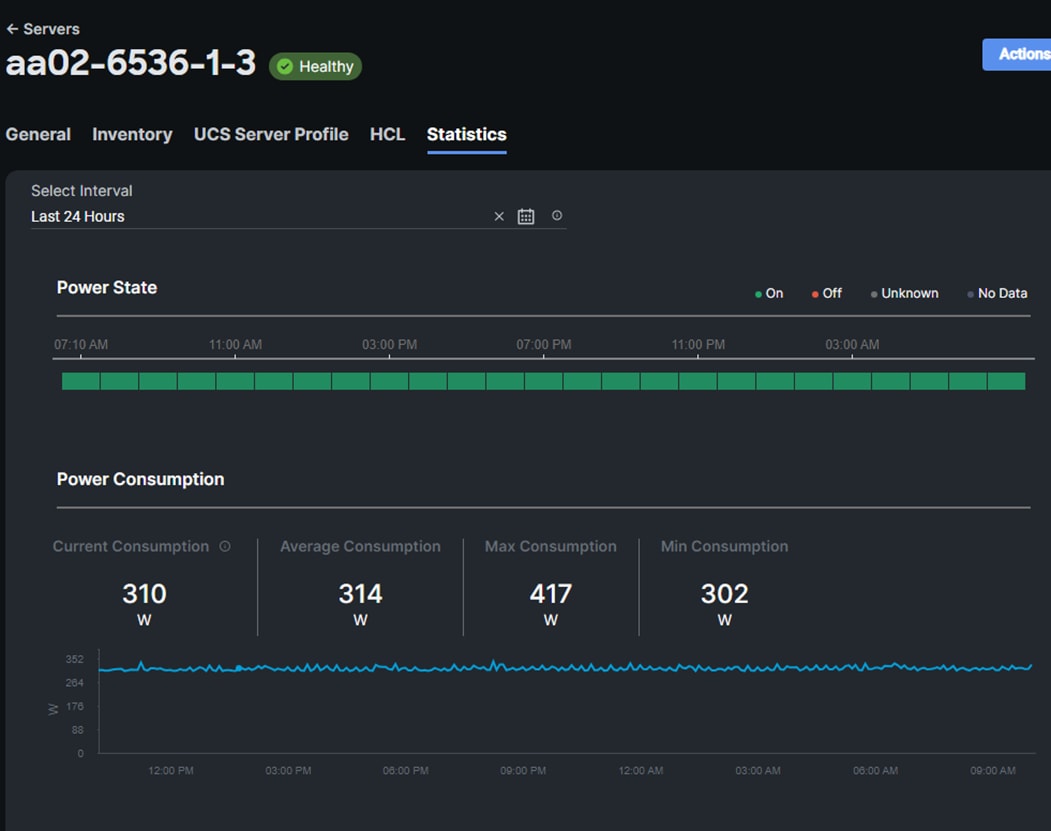
To reduce power consumption, Cisco Intersight Managed Mode provides Server BIOS policies that can be configured in this solution to provide power conservation potentially without affecting performance. These settings can be disabled if maximum performance is required. Cisco Intersight IMM provides power policies at both the Cisco X-Series Chassis and Server level, which allows you to adjust the balance of power consumption and performance to meet application needs. These policies provide multiple options specifying how Cisco UCS X-Series Chassis fans are controlled and how Cisco UCS X-Series Chassis power supplies are utilized. These policies also provide priority levels for Cisco UCS X-Series servers for power allocation to these servers.
The server BIOS policies available on the Cisco UCS X-Series M7 servers in this solution are configured according to Performance Tuning Best Practices Guide for Cisco UCS M7 Platforms. Since this is a VMware-based solution, the recommended Virtualization BIOS policy was configured.
· BIOS Policy > Processor > Processor C6 Report
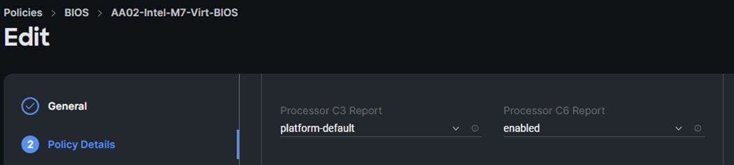
· BIOS Policy > Processor > Workload Configuration
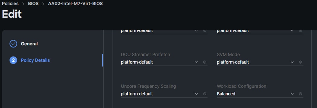
The chassis profile and policies available on the Cisco UCS X-Series in this solution are:
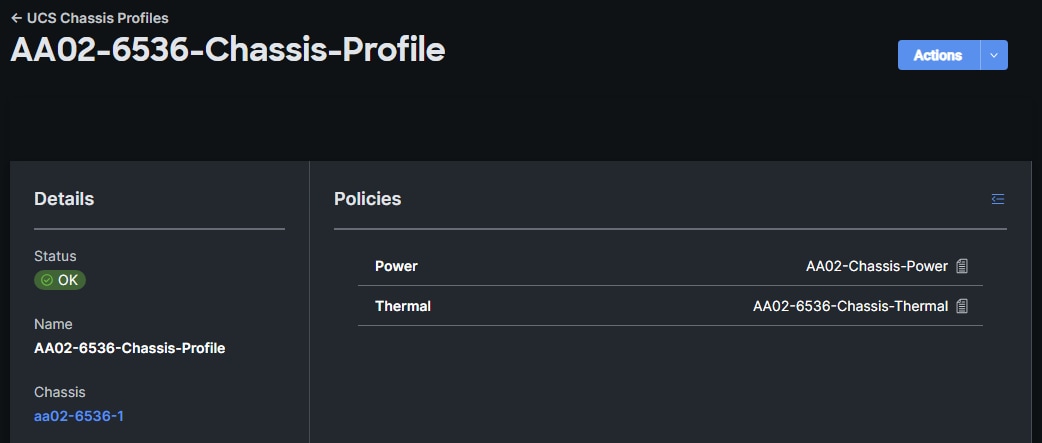
· Power Policies – For Cisco UCS X-Series and Cisco UCS B-Series Chassis
° Power Redundancy: Sets the Power Redundancy Mode of the Chassis. The Redundancy Mode determines the number of PSUs the chassis keeps as redundant. N+2 mode is only supported for Cisco UCS X-Series Chassis.
° Power Save Mode: Sets the Power Save mode of the Chassis. If the requested power budget is less than available power capacity, the additional PSUs not required to comply with redundancy policy are placed in Power Save mode. This option is only supported for Cisco UCS X-Series Chassis.
° Dynamic Power Rebalancing: Sets the Dynamic Power Rebalancing mode of the Chassis. If enabled, this mode allows the chassis to dynamically reallocate the power between servers depending on their power usage. This option is only supported for Cisco UCS X-Series Chassis.
° Extended Power Capacity: Sets the Extended Power Capacity of the Chassis. If Enabled, this mode allows chassis available power to be increased by borrowing power from redundant power supplies. This option is only supported for Cisco UCS X-Series Chassis.
° Power Allocation (Watts): Sets the Allocated Power Budget of the Chassis (in Watts). This field is only supported for Cisco UCS X-Series Chassis.
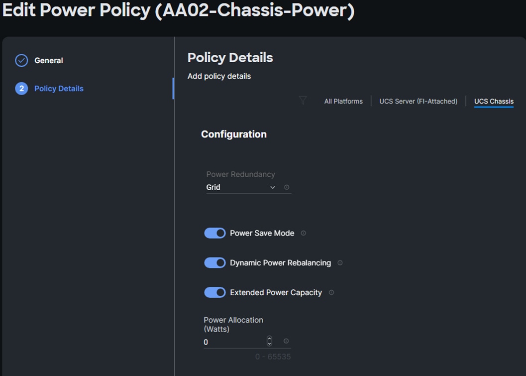
· Additional Power Policies – For Cisco UCS X-Series and Cisco UCS B-Series Servers
° Power Profiling: Sets the Power Profiling of the Server. If Enabled, this field allows the power manager to run power profiling utility to determine the power needs of the server. This field is only supported for Cisco UCS X-Series servers.
° Power Priority: Sets the Power Priority of the Server. This priority is used to determine the initial power allocation for servers. This field is only supported for Cisco UCS B-Series and Cisco UCS X-Series servers.
° Power Restore: Sets the Power Restore State of the Server. In the absence of Intersight connectivity, the chassis will use this policy to recover the host power after a power loss event. This field is only supported for Cisco UCS B-Series and Cisco UCS X-Series servers.
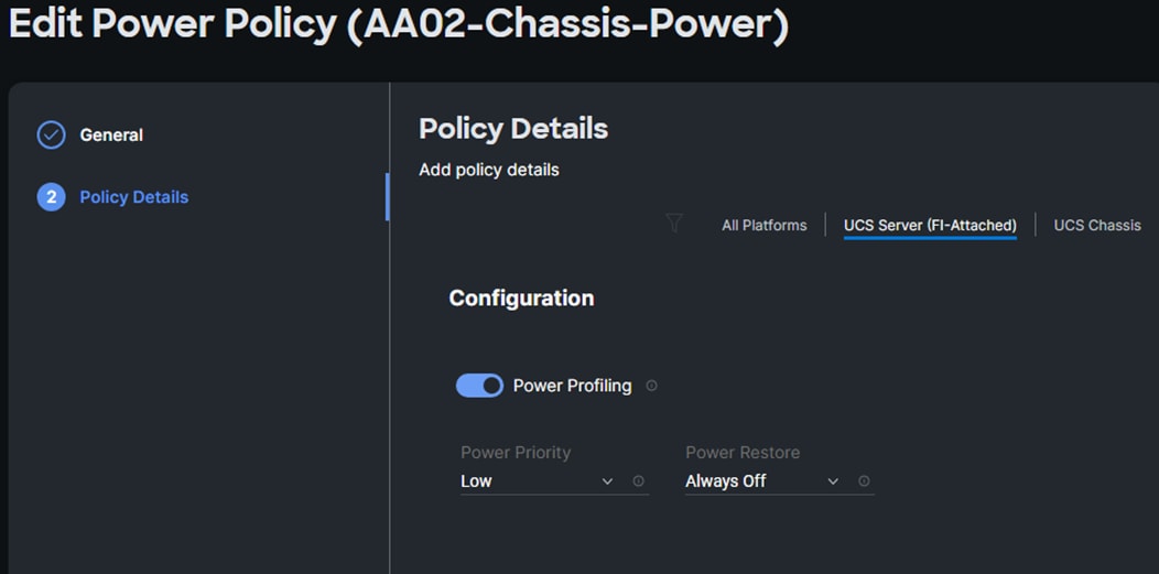
In addition to the above power consumption monitoring and policies, Cisco Intersight also offers Intersight Workload Optimizer (IWO) as an add-on service that can analyze and optimize resources in the FlexPod CI solution. IWO uses an always-on analysis engine with machine intelligence to provide specific, actionable recommendations to manage and optimize resources. By implementing the recommendations that IWO provides, you can right-size your environment and significantly reduce sub-optimal use of resources in your data center. The unused resources from consolidation can then be put on-standby until it is needed to reduce power consumption in the data center.
Note: When implementing IWO recommendations with power management policies from VMware vSphere (see below), it is important that the two components not be implemented at the same time. In this scenario, Enterprises should evaluate IWO recommendations but not implement them if there is a concern that the two would interfere with each other. At a minimum, implement changes manually rather than in an automated response to IWO recommendations.
VMware vSphere used in the FlexPod Ci solution also provides several energy management capabilities as outlined below.
For more details, see Performance Best Practices for VMware vSphere 8.0.
· Host Power Management (HPM) – When a host is powered on, this feature can reduce the power consumption of the host. This is enabled using the Power Policy Option that can be set to High Performance, Balanced, Low Power, or Custom and interacts with the server BIOS settings. In this CVD, the policy is set to Balanced (default) for a balance between power consumption and performance. Enterprises can change this policy as needed to meet the needs of their workloads and environment. In vSphere 8.0, this policy can be changed by navigating to [vSphere Cluster Name] > Host > Configure > Hardware.
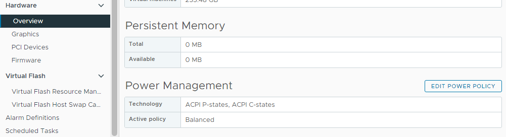
Note: The technology field shows a list of the technologies available to ESXi on that host and is derived from the server BIOS settings. For power savings, both ACPI P-states and ACPI C-states should be available to ESXi.
· Distributed Power Management (DPM) – Unlike HPM, DPM reduces power consumption by powering-off under-utilized ESXi hosts in a cluster. DPM will first migrate virtual machines to other hosts in the cluster before putting the hosts into stand-by. When demand increases, DPM will bring the hosts back online and load-balance workloads across all hosts in the cluster. DPM uses Distributed Resource Scheduling (DRS) to migrate VM workloads and is therefore configured along with DRS (at the cluster-level) as shown below.
Note: DPM will not violate VMware High Availability (HA) settings and takes it into account to meet the HA requirements.
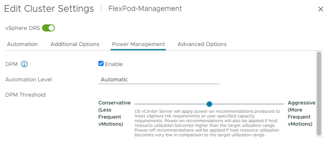
· DPM requires IPMI over LAN configuration on the UCS server which was deployed using the IPMI over LAN policy in the UCS Server Profile configuration as discussed earlier. IPMI settings must also be configured on each ESXi host in VMware vCenter by navigating to [vSphere Cluster Name] > Host > Configure > System > Power Management as shown below. In this setup, IPMI over LAN is used to power on a suspended server when demand on the cluster increases.
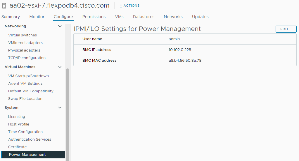
Note: DPM currently does not work with Cisco UCS C-Series servers in Intersight Managed Mode.
· Displaying VMware ESXi Host Power Usage – In addition to IPMI over LAN, local IPMI is also supported in VMware ESXi with Cisco UCS servers. VMware ESXi can use local IPMI to query a large number of server hardware sensors, including server power usage as shown below by navigating to [vSphere Cluster Name] > Host > Monitor > Hardware Health.
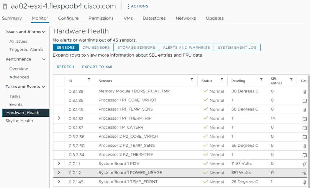
NetApp Storage Sustainability
Data centers consume a significant amount of electricity and contribute to global greenhouse gas emissions. NetApp is providing lifetime carbon footprint estimates to help you better understand the environmental impacts of NetApp storage systems.
NetApp uses Product Attribute to Impact Algorithm (PAIA) to calculate the carbon emissions associated with a product through its lifecycle, including acquisition of raw materials, manufacturing, distribution, product use, and final disposition. PAIA is a streamlined lifecycle assessment (LCA) methodology for assessing environmental impacts associated with the entire lifecycle of a product. The PAIA model was developed by the Materials Systems Laboratory at the Massachusetts Institute of Technology (MIT) and is a leading and globally accepted methodology for streamlining the product carbon footprint process.
You can use NetApp ONTAP REST API to access environment data from the NetApp ONTAP storage system for sustainability assessments. You can also utilize NetApp Harvest tool, which is an open-metrics endpoint for NetApp ONTAP and StorageGRID, to collect performance, capacity, hardware, and environmental metrics and display them in Grafana dashboards to gain sustainability insights.
Figure 67. NetApp Harvest ONTAP System Power Usage
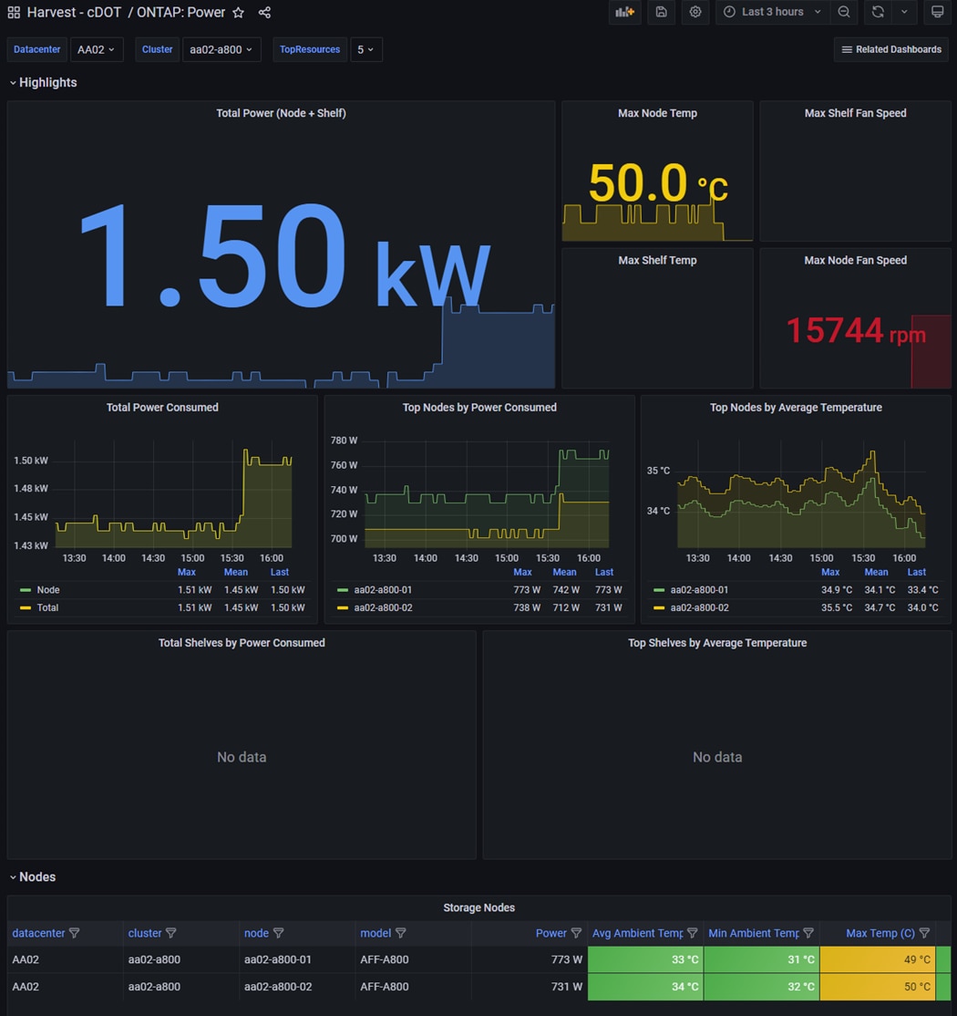
Note: For more information on NetApp storage system environmental certifications and product carbon footprint report, NetApp ONTAP REST API, and NetApp Harvest, refer to the following:
· https://www.netapp.com/company/environmental-certifications/
· https://docs.netapp.com/us-en/ontap-automation/reference/api_reference.html
· https://github.com/NetApp/harvest
Design Considerations
Some of the key design considerations for the FlexPod Datacenter with M7 are explained in this section.
Management Design Considerations
Out-of-band Management Network
The management interface of every physical device in FlexPod is connected to a dedicated out-of-band management switch which can be part of the existing management infrastructure in your environment. The out-of-band management network provides management access to all the devices in the FlexPod environment for initial and on-going configuration changes. The routing and switching configuration for this network is independent of FlexPod deployment and therefore changes in FlexPod configurations do not impact management access to the devices. In this CVD, the out-of-band management network is connected to the Cisco Nexus uplinks to allow Cisco UCS CIMC connectivity and to provide the out-of-band management network to management virtual machines when necessary.
In-band Management Network
The in-band management VLAN configuration is part of FlexPod design. The in-band VLAN is configured on Cisco Nexus switches and Cisco UCS within the FlexPod solution to provide management connectivity for vCenter, ESXi and other management components. The changes to FlexPod configuration can impact the in-band management network and misconfigurations can cause loss of access to the management components hosted by FlexPod. It is also required that the out-of-band management network have Layer 3 access to the in-band management network so that management virtual machines with only in-band management interfaces can manage FlexPod hardware devices.
vCenter Deployment Consideration
While hosting the vCenter on the same ESXi hosts that the vCenter is managing is supported, it is a best practice to deploy the vCenter on a separate management infrastructure. Similarly, the ESXi hosts in this new FlexPod with end-to-end 100Gbps Ethernet environment can also be added to an existing vCenter. The in-band management VLAN will provide connectivity between the vCenter and the ESXi hosts deployed in the new FlexPod environment. In this CVD deployment guide, the steps for installing vCenter on FlexPod environment are included, but the vCenter can also be installed in another environment with L3 reachability to the ESXi hosts in the FlexPod.
Jumbo Frames
An MTU of 9216 is configured at all network levels to allow jumbo frames as needed by the guest OS and application layer. This allows the network at every point to negotiate an MTU up to 9000 with the end point. For VLANs that leave the FlexPod via the Nexus switch uplinks (OOB-MGMT, IB-MGMT, VM-Traffic), all endpoints should have MTU 1500. For Storage and vMotion VLANs that stay within the FlexPod, MTU 9000 should be used on all endpoints for higher performance. It is important that all endpoints within a VLAN have the same MTU setting. It is important to remember that most virtual machine network interfaces have MTU 1500 set by default and that it may be difficult to change this setting to 9000, especially on a large number of virtual machines. This difficulty should be considered when implementing storage protocols such as CIFS or SMB. Note that a VLAN tagged trunk can contain both VLANs with MTU 1500 and VLANs with MTU 9000 interfaces.
NTP
For many reasons, including authentication and log correlation, it is critical within a FlexPod environment that all components are properly synchronized to a time-of-day clock. In order to support this synchronization, all components of FlexPod support network time protocol (NTP). In the FlexPod setup, the two Cisco Nexus switches are synchronized via NTP to at least two external NTP sources. Cisco Nexus NTP distribution is then set up and all the other components of the FlexPod can use the IP of any of the switches’ L3 interfaces, including mgmt0 as an NTP source. If you already have NTP distribution in place, that can be used instead of the Cisco Nexus switch NTP distribution.
Boot From SAN
When utilizing Cisco UCS Server technology with shared storage, it is recommended to configure boot from SAN and store the boot partitions on remote storage. This enables architects and administrators to take full advantage of the stateless nature of Cisco UCS Server Profiles for hardware flexibility across the server hardware and overall portability of server identity. Boot from SAN also removes the need to populate local server storage thereby reducing cost and administrative overhead.
UEFI Secure Boot
This validation of FlexPod uses Unified Extensible Firmware Interface (UEFI) Secure Boot. UEFI is a specification that defines a software interface between an operating system and platform firmware. With UEFI secure boot enabled, all executables, such as boot loaders and adapter drivers, are authenticated as properly signed by the BIOS before they can be loaded. Additionally, a Trusted Platform Module (TPM) is also installed in the Cisco UCS compute nodes. VMware ESXi 8.0 supports UEFI Secure Boot and VMware vCenter 8.0 supports UEFI Secure Boot Attestation between the TPM module and ESXi, validating that UEFI Secure Boot has properly taken place.
VMware Virtual Volumes
This validation of FlexPod supports VMware Virtual Volumes (vVols) for those looking for more granular control of their SAN environment. SAN storage systems using Fibre Channel and iSCSI lack the ability to manage individual VM files and disks from the storage system. This makes it difficult for the storage system to directly manage individual VM storage performance, cloning, and protection. vVols bring storage granularity to the SAN environment. NetApp VASA Provider enables you to create and manage vVols. A vVols datastore consists of one or more FlexVol volumes within a storage container (also called "backing storage"). All the FlexVol volumes within the storage container must use the same protocol (NFS, iSCSI, or FCP) and the same SVMs. A virtual machine can be spread across one vVols datastore or multiple vVols datastores.
NVMe over Fibre Channel
This validation of FlexPod supports NVMe over Fibre Channel (FC-NVMe) to provide the high-performance and low-latency benefits of NVMe across fabrics connecting servers and storage. FC-NVMe is implemented through the Fibre Channel over NVMe (FC-NVMe) standard which is designed to enable NVMe based message commands to transfer data and status information between a host computer and a target storage subsystem over a Fibre Channel network fabric. FC-NVMe simplifies the NVMe command sets into basic FCP instructions.
FC-NVMe requires the creation of additional Fibre Channel interfaces on Cisco UCS Compute nodes and NetApp controllers. Appropriate zoning configurations are also required on Cisco MDS switches.
NVMe over TCP
This validation of FlexPod supports NVMe over TCP (NVMe-TCP) that provides excellent performance scalability for large scale deployments and longer distances. NVMe-TCP has almost all the benefits of FC-NVMe while radically simplifying the networking requirements, including operating over routed networks. The NVMe-TCP targets are connected to the network through a standard TCP infrastructure using Ethernet switches and host-side adapters. NVMe-TCP target is supported beginning with ONTAP 9.10.1 release.
NVMe-TCP requires configuration of 2 additional LIFs per controller. Similarly, 2 additional VMkernel ports are required on the ESXi hosts.
Deployment Hardware and Software
This chapter contains the following:
· Hardware and Software Revisions
Hardware and Software Revisions
Table 2 lists the hardware and software used in this solution
Table 2. Hardware and Software Revisions
| Component |
Software |
|
| Network |
Cisco Nexus 93360YC-FX2 |
10.2(5) |
|
|
Cisco MDS 9132T |
9.3(2) |
| Compute |
Cisco UCS Fabric Interconnect 6536 and CISCO UCS 9108-100G IFM |
4.2(3d) |
|
|
Cisco UCS X210C M7 |
5.1(1.230052) |
|
|
Cisco UCS C220/240 M7 |
4.3(1.230138) |
|
|
VMware ESXi |
8.0.0 |
|
|
Cisco UCS VIC ENIC Driver for ESXi |
1.0.45.0 |
|
|
Cisco UCS VIC FNIC Driver for ESXi |
5.0.0.37 |
|
|
VMware vCenter Appliance |
8.0.0C or latest |
|
|
Cisco Intersight Assist Virtual Appliance |
1.0.9-588 (automatically upgrades to current release) |
| Storage |
NetApp AFF A400/ A800 |
ONTAP 9.12.1 |
|
|
NetApp ONTAP Tools for VMware vSphere |
9.12 |
|
|
NetApp Active IQ Unified Manager |
9.12 |
|
|
NetApp SnapCenter Plug-in for VMware vSphere |
4.8.0 |
John George, Technical Marketing Engineer, Cisco Systems, Inc.
John has been involved in designing, developing, validating, and supporting the FlexPod Converged Infrastructure since it was developed over 12 years ago. Before his roles with FlexPod, he supported and administered a large worldwide training network and VPN infrastructure. John holds a master’s degree in computer engineering from Clemson University.
Roney Daniel, Technical Marketing Engineer, Hybrid Cloud Infra & OEM Solutions, NetApp, Inc.
Roney Daniel is a Technical Marketing engineer at NetApp. He has over 25 years of experience in the networking industry. Prior to NetApp, Roney worked at Cisco Systems in various roles with Cisco TAC, Financial Test Lab, Systems and solution engineering BUs and Cisco IT. He has a bachelor's degree in Electronics and Communication engineering and is a data center Cisco Certified Internetwork Expert (CCIE 42731).
Kamini Singh, Technical Marketing Engineer, Hybrid Cloud Infra & OEM Solutions, NetApp, Inc.
Kamini Singh is a Technical Marketing engineer at NetApp. She has three years of experience in data center infrastructure solutions. Kamini focuses on FlexPod hybrid cloud infrastructure solution design, implementation, validation, automation, and sales enablement. Kamini holds a bachelor’s degree in Electronics and Communication and a master’s degree in communication systems.
Acknowledgements
For their support and contribution to the design, validation, and creation of this Cisco Validated Design, the authors would like to thank:
· Haseeb Niazi, Principal Engineer, Cisco Systems, Inc.
· Archana Sharma, Engineering Technical Leader, Cisco Systems, Inc.
· Jyh-shing Chen, Senior Technical Marketing Engineer, NetApp, Inc.
This appendix is organized into the following:
· Compute
· Network
· Storage
Cisco Intersight: https://www.intersight.com
Cisco Intersight Managed Mode: https://www.cisco.com/c/en/us/td/docs/unified_computing/Intersight/b_Intersight_Managed_Mode_Configuration_Guide.html
Cisco Unified Computing System: http://www.cisco.com/en/US/products/ps10265/index.html
Cisco UCS 6536 Fabric Interconnects: https://www.cisco.com/c/en/us/products/collateral/servers-unified-computing/ucs6536-fabric-interconnect-ds.html
Cisco Nexus 9000 Series Switches: http://www.cisco.com/c/en/us/products/switches/nexus-9000-series-switches/index.html
Cisco MDS 9132T Switches: https://www.cisco.com/c/en/us/products/collateral/storage-networking/mds-9100-series-multilayer-fabric-switches/datasheet-c78-739613.html
NetApp ONTAP: https://docs.netapp.com/ontap-9/index.jsp
NetApp Active IQ Unified Manager: https://community.netapp.com/t5/Tech-ONTAP-Blogs/Introducing-NetApp-Active-IQ-Unified-Manager-9-11/ba-p/435519
NetApp ONTAP Storage Connector for Cisco Intersight: https://www.netapp.com/pdf.html?item=/media/25001-tr-4883.pdf
NetApp ONTAP tools for VMware vSphere: https://docs.netapp.com/us-en/ontap-tools-vmware-vsphere/index.html
NetApp SnapCenter: https://docs.netapp.com/us-en/snapcenter/index.html
VMware vCenter Server: http://www.vmware.com/products/vcenter-server/overview.html
VMware vSphere: https://www.vmware.com/products/vsphere
Cisco UCS Hardware Compatibility Matrix: https://ucshcltool.cloudapps.cisco.com/public/
VMware and Cisco Unified Computing System: http://www.vmware.com/resources/compatibility
NetApp Interoperability Matrix Tool: http://support.netapp.com/matrix/
AAA—Authentication, Authorization, and Accounting
ACP—Access-Control Policy
ACI—Cisco Application Centric Infrastructure
ACK—Acknowledge or Acknowledgement
ACL—Access-Control List
AD—Microsoft Active Directory
AFI—Address Family Identifier
AMP—Cisco Advanced Malware Protection
AP—Access Point
API—Application Programming Interface
APIC— Cisco Application Policy Infrastructure Controller (ACI)
ASA—Cisco Adaptative Security Appliance
ASM—Any-Source Multicast (PIM)
ASR—Aggregation Services Router
Auto-RP—Cisco Automatic Rendezvous Point protocol (multicast)
AVC—Application Visibility and Control
BFD—Bidirectional Forwarding Detection
BGP—Border Gateway Protocol
BMS—Building Management System
BSR—Bootstrap Router (multicast)
BYOD—Bring Your Own Device
CAPWAP—Control and Provisioning of Wireless Access Points Protocol
CDP—Cisco Discovery Protocol
CEF—Cisco Express Forwarding
CMD—Cisco Meta Data
CPU—Central Processing Unit
CSR—Cloud Services Routers
CTA—Cognitive Threat Analytics
CUWN—Cisco Unified Wireless Network
CVD—Cisco Validated Design
CYOD—Choose Your Own Device
DC—Data Center
DHCP—Dynamic Host Configuration Protocol
DM—Dense-Mode (multicast)
DMVPN—Dynamic Multipoint Virtual Private Network
DMZ—Demilitarized Zone (firewall/networking construct)
DNA—Cisco Digital Network Architecture
DNS—Domain Name System
DORA—Discover, Offer, Request, ACK (DHCP Process)
DWDM—Dense Wavelength Division Multiplexing
ECMP—Equal Cost Multi Path
EID—Endpoint Identifier
EIGRP—Enhanced Interior Gateway Routing Protocol
EMI—Electromagnetic Interference
ETR—Egress Tunnel Router (LISP)
EVPN—Ethernet Virtual Private Network (BGP EVPN with VXLAN data plane)
FHR—First-Hop Router (multicast)
FHRP—First-Hop Redundancy Protocol
FMC—Cisco Firepower Management Center
FTD—Cisco Firepower Threat Defense
GBAC—Group-Based Access Control
GbE—Gigabit Ethernet
Gbit/s—Gigabits Per Second (interface/port speed reference)
GRE—Generic Routing Encapsulation
GRT—Global Routing Table
HA—High-Availability
HQ—Headquarters
HSRP—Cisco Hot-Standby Routing Protocol
HTDB—Host-tracking Database (SD-Access control plane node construct)
IBNS—Identity-Based Networking Services (IBNS 2.0 is the current version)
ICMP— Internet Control Message Protocol
IDF—Intermediate Distribution Frame; essentially a wiring closet.
IEEE—Institute of Electrical and Electronics Engineers
IETF—Internet Engineering Task Force
IGP—Interior Gateway Protocol
IID—Instance-ID (LISP)
IOE—Internet of Everything
IoT—Internet of Things
IP—Internet Protocol
IPAM—IP Address Management
IPS—Intrusion Prevention System
IPSec—Internet Protocol Security
ISE—Cisco Identity Services Engine
ISR—Integrated Services Router
IS-IS—Intermediate System to Intermediate System routing protocol
ITR—Ingress Tunnel Router (LISP)
LACP—Link Aggregation Control Protocol
LAG—Link Aggregation Group
LAN—Local Area Network
L2 VNI—Layer 2 Virtual Network Identifier; as used in SD-Access Fabric, a VLAN.
L3 VNI— Layer 3 Virtual Network Identifier; as used in SD-Access Fabric, a VRF.
LHR—Last-Hop Router (multicast)
LISP—Location Identifier Separation Protocol
MAC—Media Access Control Address (OSI Layer 2 Address)
MAN—Metro Area Network
MEC—Multichassis EtherChannel, sometimes referenced as MCEC
MDF—Main Distribution Frame; essentially the central wiring point of the network.
MnT—Monitoring and Troubleshooting Node (Cisco ISE persona)
MOH—Music on Hold
MPLS—Multiprotocol Label Switching
MR—Map-resolver (LISP)
MS—Map-server (LISP)
MSDP—Multicast Source Discovery Protocol (multicast)
MTU—Maximum Transmission Unit
NAC—Network Access Control
NAD—Network Access Device
NAT—Network Address Translation
NBAR—Cisco Network-Based Application Recognition (NBAR2 is the current version).
NFV—Network Functions Virtualization
NSF—Non-Stop Forwarding
OSI—Open Systems Interconnection model
OSPF—Open Shortest Path First routing protocol
OT—Operational Technology
PAgP—Port Aggregation Protocol
PAN—Primary Administration Node (Cisco ISE persona)
PCI DSS—Payment Card Industry Data Security Standard
PD—Powered Devices (PoE)
PETR—Proxy-Egress Tunnel Router (LISP)
PIM—Protocol-Independent Multicast
PITR—Proxy-Ingress Tunnel Router (LISP)
PnP—Plug-n-Play
PoE—Power over Ethernet (Generic term, may also refer to IEEE 802.3af, 15.4W at PSE)
PoE+—Power over Ethernet Plus (IEEE 802.3at, 30W at PSE)
PSE—Power Sourcing Equipment (PoE)
PSN—Policy Service Node (Cisco ISE persona)
pxGrid—Platform Exchange Grid (Cisco ISE persona and publisher/subscriber service)
PxTR—Proxy-Tunnel Router (LISP – device operating as both a PETR and PITR)
QoS—Quality of Service
RADIUS—Remote Authentication Dial-In User Service
REST—Representational State Transfer
RFC—Request for Comments Document (IETF)
RIB—Routing Information Base
RLOC—Routing Locator (LISP)
RP—Rendezvous Point (multicast)
RP—Redundancy Port (WLC)
RP—Route Processer
RPF—Reverse Path Forwarding
RR—Route Reflector (BGP)
RTT—Round-Trip Time
SA—Source Active (multicast)
SAFI—Subsequent Address Family Identifiers (BGP)
SD—Software-Defined
SDA—Cisco Software Defined-Access
SDN—Software-Defined Networking
SFP—Small Form-Factor Pluggable (1 GbE transceiver)
SFP+— Small Form-Factor Pluggable (10 GbE transceiver)
SGACL—Security-Group ACL
SGT—Scalable Group Tag, sometimes reference as Security Group Tag
SM—Spare-mode (multicast)
SNMP—Simple Network Management Protocol
SSID—Service Set Identifier (wireless)
SSM—Source-Specific Multicast (PIM)
SSO—Stateful Switchover
STP—Spanning-tree protocol
SVI—Switched Virtual Interface
SVL—Cisco StackWise Virtual
SWIM—Software Image Management
SXP—Scalable Group Tag Exchange Protocol
Syslog—System Logging Protocol
TACACS+—Terminal Access Controller Access-Control System Plus
TCP—Transmission Control Protocol (OSI Layer 4)
UCS— Cisco Unified Computing System
UDP—User Datagram Protocol (OSI Layer 4)
UPoE—Cisco Universal Power Over Ethernet (60W at PSE)
UPoE+— Cisco Universal Power Over Ethernet Plus (90W at PSE)
URL—Uniform Resource Locator
VLAN—Virtual Local Area Network
VM—Virtual Machine
VN—Virtual Network, analogous to a VRF in SD-Access
VNI—Virtual Network Identifier (VXLAN)
vPC—virtual Port Channel (Cisco Nexus)
VPLS—Virtual Private LAN Service
VPN—Virtual Private Network
VPNv4—BGP address family that consists of a Route-Distinguisher (RD) prepended to an IPv4 prefix
VPWS—Virtual Private Wire Service
VRF—Virtual Routing and Forwarding
VSL—Virtual Switch Link (Cisco VSS component)
VSS—Cisco Virtual Switching System
VXLAN—Virtual Extensible LAN
WAN—Wide-Area Network
WLAN—Wireless Local Area Network (generally synonymous with IEEE 802.11-based networks)
WoL—Wake-on-LAN
xTR—Tunnel Router (LISP – device operating as both an ETR and ITR)
This glossary addresses some terms used in this document, for the purposes of aiding understanding. This is not a complete list of all multicloud terminology. Some Cisco product links are supplied here also, where considered useful for the purposes of clarity, but this is by no means intended to be a complete list of all applicable Cisco products.
| aaS/XaaS (IT capability provided as a Service) |
Some IT capability, X, provided as a service (XaaS). Some benefits are:
● The provider manages the design, implementation, deployment, upgrades, resiliency, scalability, and overall delivery of the service and the infrastructure that supports it.
● There are very low barriers to entry, so that services can be quickly adopted and dropped in response to business demand, without the penalty of inefficiently utilized CapEx.
● The service charge is an IT OpEx cost (pay-as-you-go), whereas the CapEx and the service infrastructure is the responsibility of the provider.
● Costs are commensurate to usage and hence more easily controlled with respect to business demand and outcomes.
Such services are typically implemented as “microservices,” which are accessed via REST APIs. This architectural style supports composition of service components into systems. Access to and management of aaS assets is via a web GUI and/or APIs, such that Infrastructure-as-code (IaC) techniques can be used for automation, for example, Ansible and Terraform. The provider can be any entity capable of implementing an aaS “cloud-native” architecture. The cloud-native architecture concept is well-documented and supported by open-source software and a rich ecosystem of services such as training and consultancy. The provider can be an internal IT department or any of many third-party companies using and supporting the same open-source platforms. Service access control, integrated with corporate IAM, can be mapped to specific users and business activities, enabling consistent policy controls across services, wherever they are delivered from. |
| Ansible |
An infrastructure automation tool, used to implement processes for instantiating and configuring IT service components, such as VMs on an IaaS platform. Supports the consistent execution of processes defined in YAML “playbooks” at scale, across multiple targets. Because the Ansible artefacts (playbooks) are text-based, they can be stored in a Source Code Management (SCM) system, such as GitHub. This allows for software development like processes to be applied to infrastructure automation, such as, Infrastructure-as-code (see IaC below). |
| AWS (Amazon Web Services) |
Provider of IaaS and PaaS. |
| Azure |
Microsoft IaaS and PaaS. |
| Co-located data center |
“A colocation center (CoLo)…is a type of data center where equipment, space, and bandwidth are available for rental to retail customers. Colocation facilities provide space, power, cooling, and physical security for the server, storage, and networking equipment of other firms and also connect them to a variety of telecommunications and network service providers with a minimum of cost and complexity.” |
| Containers (Docker) |
A (Docker) container is a means to create a package of code for an application and its dependencies, such that the application can run on different platforms which support the Docker environment. In the context of aaS, microservices are typically packaged within Linux containers orchestrated by Kubernetes (K8s). https://www.cisco.com/c/en/us/products/cloud-systems-management/containerplatform/index.html |
| DevOps |
The underlying principle of DevOps is that the application development and operations teams should work closely together, ideally within the context of a toolchain that automates the stages of development, test, deployment, monitoring, and issue handling. DevOps is closely aligned with IaC, continuous integration and deployment (CI/CD), and Agile software development practices. |
| Edge compute |
Edge compute is the idea that it can be more efficient to process data at the edge of a network, close to the endpoints that originate that data, or to provide virtualized access services, such as at the network edge. This could be for reasons related to low latency response, reduction of the amount of unprocessed data being transported, efficiency of resource utilization, and so on. The generic label for this is Multi-access Edge Computing (MEC), or Mobile Edge Computing for mobile networks specifically. From an application experience perspective, it is important to be able to utilize, at the edge, the same operations model, processes, and tools used for any other compute node in the system. |
| IaaS (Infrastructure as-a-Service) |
Infrastructure components provided aaS, located in data centers operated by a provider, typically accessed over the public Internet. IaaS provides a base platform for the deployment of workloads, typically with containers and Kubernetes (K8s). |
| IaC (Infrastructure as-Code) |
Given the ability to automate aaS via APIs, the implementation of the automation is typically via Python code, Ansible playbooks, and similar. These automation artefacts are programming code that define how the services are consumed. As such, they can be subject to the same code management and software development regimes as any other body of code. This means that infrastructure automation can be subject to all of the quality and consistency benefits, CI/CD, traceability, automated testing, compliance checking, and so on, that could be applied to any coding project. |
| IAM (Identity and Access Management) |
IAM is the means to control access to IT resources so that only those explicitly authorized to access given resources can do so. IAM is an essential foundation to a secure multicloud environment. |
| IBM (Cloud) |
IBM IaaS and PaaS. |
| Intersight |
Cisco Intersight™ is a Software-as-a-Service (SaaS) infrastructure lifecycle management platform that delivers simplified configuration, deployment, maintenance, and support. https://www.cisco.com/c/en/us/products/servers-unified-computing/intersight/index.html |
| GCP (Google Cloud Platform) |
Google IaaS and PaaS. |
| Kubernetes (K8s) |
Kubernetes is an open-source system for automating deployment, scaling, and management of containerized applications. |
| Microservices |
A microservices architecture is characterized by processes implementing fine-grained services, typically exposed via REST APIs and which can be composed into systems. The processes are often container-based, and the instantiation of the services often managed with Kubernetes. Microservices managed in this way are intrinsically well suited for deployment into IaaS environments, and as such, are the basis of a cloud native architecture. |
| PaaS (Platform-as-a-Service) |
PaaS is a layer of value-add services, typically for application development, deployment, monitoring, and general lifecycle management. The use of IaC with IaaS and PaaS is very closely associated with DevOps practices. |
| Private on-premises data center |
A data center infrastructure housed within an environment owned by a given enterprise is distinguished from other forms of data center, with the implication that the private data center is more secure, given that access is restricted to those authorized by the enterprise. Thus, circumstances can arise where very sensitive IT assets are only deployed in a private data center, in contrast to using public IaaS. For many intents and purposes, the underlying technology can be identical, allowing for hybrid deployments where some IT assets are privately deployed but also accessible to other assets in public IaaS. IAM, VPNs, firewalls, and similar are key technologies needed to underpin the security of such an arrangement. |
| REST API |
Representational State Transfer (REST) APIs is a generic term for APIs accessed over HTTP(S), typically transporting data encoded in JSON or XML. REST APIs have the advantage that they support distributed systems, communicating over HTTP, which is a well-understood protocol from a security management perspective. REST APIs are another element of a cloud-native applications architecture, alongside microservices. https://en.wikipedia.org/wiki/Representational_state_transfer |
| SaaS (Software-as-a-Service) |
End-user applications provided “aaS” over the public Internet, with the underlying software systems and infrastructure owned and managed by the provider. |
| SAML (Security Assertion Markup Language) |
Used in the context of Single-Sign-On (SSO) for exchanging authentication and authorization data between an identity provider, typically an IAM system, and a service provider (some form of SaaS). The SAML protocol exchanges XML documents that contain security assertions used by the aaS for access control decisions. https://en.wikipedia.org/wiki/Security_Assertion_Markup_Language |
| Terraform |
An open-source IaC software tool for cloud services, based on declarative configuration files. |
For comments and suggestions about this guide and related guides, join the discussion on Cisco Community at https://cs.co/en-cvds.
CVD Program
ALL DESIGNS, SPECIFICATIONS, STATEMENTS, INFORMATION, AND RECOMMENDATIONS (COLLECTIVELY, "DESIGNS") IN THIS MANUAL ARE PRESENTED "AS IS," WITH ALL FAULTS. CISCO AND ITS SUPPLIERS DISCLAIM ALL WARRANTIES, INCLUDING, WITHOUT LIMITATION, THE WARRANTY OF MERCHANTABILITY, FITNESS FOR A PARTICULAR PURPOSE AND NONINFRINGEMENT OR ARISING FROM A COURSE OF DEALING, USAGE, OR TRADE PRACTICE. IN NO EVENT SHALL CISCO OR ITS SUPPLIERS BE LIABLE FOR ANY INDIRECT, SPECIAL, CONSEQUENTIAL, OR INCIDENTAL DAMAGES, INCLUDING, WITHOUT LIMITATION, LOST PROFITS OR LOSS OR DAMAGE TO DATA ARISING OUT OF THE USE OR INABILITY TO USE THE DESIGNS, EVEN IF CISCO OR ITS SUPPLIERS HAVE BEEN ADVISED OF THE POSSIBILITY OF SUCH DAMAGES.
THE DESIGNS ARE SUBJECT TO CHANGE WITHOUT NOTICE. USERS ARE SOLELY RESPONSIBLE FOR THEIR APPLICATION OF THE DESIGNS. THE DESIGNS DO NOT CONSTITUTE THE TECHNICAL OR OTHER PROFESSIONAL ADVICE OF CISCO, ITS SUPPLIERS OR PARTNERS. USERS SHOULD CONSULT THEIR OWN TECHNICAL ADVISORS BEFORE IMPLEMENTING THE DESIGNS. RESULTS MAY VARY DEPENDING ON FACTORS NOT TESTED BY CISCO.
CCDE, CCENT, Cisco Eos, Cisco Lumin, Cisco Nexus, Cisco StadiumVision, Cisco TelePresence, Cisco WebEx, the Cisco logo, DCE, and Welcome to the Human Network are trademarks; Changing the Way We Work, Live, Play, and Learn and Cisco Store are service marks; and Access Registrar, Aironet, AsyncOS, Bringing the Meeting To You, Catalyst, CCDA, CCDP, CCIE, CCIP, CCNA, CCNP, CCSP, CCVP, Cisco, the Cisco Certified Internetwork Expert logo, Cisco IOS, Cisco Press, Cisco Systems, Cisco Systems Capital, the Cisco Systems logo, Cisco Unified Computing System (Cisco UCS), Cisco UCS B-Series Blade Servers, Cisco UCS C-Series Rack Servers, Cisco UCS S-Series Storage Servers, Cisco UCS Manager, Cisco UCS Management Software, Cisco Unified Fabric, Cisco Application Centric Infrastructure, Cisco Nexus 9000 Series, Cisco Nexus 7000 Series. Cisco Prime Data Center Network Manager, Cisco NX-OS Software, Cisco MDS Series, Cisco Unity, Collaboration Without Limitation, EtherFast, EtherSwitch, Event Center, Fast Step, Follow Me Browsing, FormShare, GigaDrive, HomeLink, Internet Quotient, IOS, iPhone, iQuick Study, LightStream, Linksys, MediaTone, MeetingPlace, MeetingPlace Chime Sound, MGX, Networkers, Networking Academy, Network Registrar, PCNow, PIX, PowerPanels, ProConnect, ScriptShare, SenderBase, SMARTnet, Spectrum Expert, StackWise, The Fastest Way to Increase Your Internet Quotient, TransPath, WebEx, and the WebEx logo are registered trade-marks of Cisco Systems, Inc. and/or its affiliates in the United States and certain other countries. (LDW_P7)
All other trademarks mentioned in this document or website are the property of their respective owners. The use of the word partner does not imply a partnership relationship between Cisco and any other company. (0809R)