FlexPod Datacenter with VMware vSphere 6.5 Design Guide
Available Languages
FlexPod Datacenter with VMware vSphere 6.5 Design Guide
Last Updated: May 5, 2017

About Cisco Validated Designs
The Cisco Validated Designs (CVD) program consists of systems and solutions designed, tested, and documented to facilitate faster, more reliable, and more predictable customer deployments. For more information, visit:
http://www.cisco.com/go/designzone.
ALL DESIGNS, SPECIFICATIONS, STATEMENTS, INFORMATION, AND RECOMMENDATIONS (COLLECTIVELY, "DESIGNS") IN THIS MANUAL ARE PRESENTED "AS IS," WITH ALL FAULTS. CISCO AND ITS SUPPLIERS DISCLAIM ALL WARRANTIES, INCLUDING, WITHOUT LIMITATION, THE WARRANTY OF MERCHANTABILITY, FITNESS FOR A PARTICULAR PURPOSE AND NONINFRINGEMENT OR ARISING FROM A COURSE OF DEALING, USAGE, OR TRADE PRACTICE. IN NO EVENT SHALL CISCO OR ITS SUPPLIERS BE LIABLE FOR ANY INDIRECT, SPECIAL, CONSEQUENTIAL, OR INCIDENTAL DAMAGES, INCLUDING, WITHOUT LIMITATION, LOST PROFITS OR LOSS OR DAMAGE TO DATA ARISING OUT OF THE USE OR INABILITY TO USE THE DESIGNS, EVEN IF CISCO OR ITS SUPPLIERS HAVE BEEN ADVISED OF THE POSSIBILITY OF SUCH DAMAGES.
THE DESIGNS ARE SUBJECT TO CHANGE WITHOUT NOTICE. USERS ARE SOLELY RESPONSIBLE FOR THEIR APPLICATION OF THE DESIGNS. THE DESIGNS DO NOT CONSTITUTE THE TECHNICAL OR OTHER PROFESSIONAL ADVICE OF CISCO, ITS SUPPLIERS OR PARTNERS. USERS SHOULD CONSULT THEIR OWN TECHNICAL ADVISORS BEFORE IMPLEMENTING THE DESIGNS. RESULTS MAY VARY DEPENDING ON FACTORS NOT TESTED BY CISCO.
CCDE, CCENT, Cisco Eos, Cisco Lumin, Cisco Nexus, Cisco StadiumVision, Cisco TelePresence, Cisco WebEx, the Cisco logo, DCE, and Welcome to the Human Network are trademarks; Changing the Way We Work, Live, Play, and Learn and Cisco Store are service marks; and Access Registrar, Aironet, AsyncOS, Bringing the Meeting To You, Catalyst, CCDA, CCDP, CCIE, CCIP, CCNA, CCNP, CCSP, CCVP, Cisco, the Cisco Certified Internetwork Expert logo, Cisco IOS, Cisco Press, Cisco Systems, Cisco Systems Capital, the Cisco Systems logo, Cisco Unified Computing System (Cisco UCS), Cisco UCS B-Series Blade Servers, Cisco UCS C-Series Rack Servers, Cisco UCS S-Series Storage Servers, Cisco UCS Manager, Cisco UCS Management Software, Cisco Unified Fabric, Cisco Application Centric Infrastructure, Cisco Nexus 9000 Series, Cisco Nexus 7000 Series. Cisco Prime Data Center Network Manager, Cisco NX-OS Software, Cisco MDS Series, Cisco Unity, Collaboration Without Limitation, EtherFast, EtherSwitch, Event Center, Fast Step, Follow Me Browsing, FormShare, GigaDrive, HomeLink, Internet Quotient, IOS, iPhone, iQuick Study, LightStream, Linksys, MediaTone, MeetingPlace, MeetingPlace Chime Sound, MGX, Networkers, Networking Academy, Network Registrar, PCNow, PIX, PowerPanels, ProConnect, ScriptShare, SenderBase, SMARTnet, Spectrum Expert, StackWise, The Fastest Way to Increase Your Internet Quotient, TransPath, WebEx, and the WebEx logo are registered trademarks of Cisco Systems, Inc. and/or its affiliates in the United States and certain other countries.
All other trademarks mentioned in this document or website are the property of their respective owners. The use of the word partner does not imply a partnership relationship between Cisco and any other company. (0809R)
© 2017 Cisco Systems, Inc. All rights reserved.
Table of Contents
NetApp Storage Virtual Machine (SVM)
iSCSI and FC: Network and Storage Connectivity
Distributed Switch Options Virtual Switching
Cisco Nexus 9000 Best Practices
Bringing Together 40Gb End-to-End
Cisco Unified Computing System
Cisco UCS 6300 and UCS 6200 Fabric Interconnects
Cisco UCS Design Options within this FlexPod
Validated Hardware and Software
Cisco Validated Designs consist of systems and solutions that are designed, tested, and documented to facilitate and improve customer deployments. These designs incorporate a wide range of technologies and products into a portfolio of solutions that have been developed to address the business needs of our customers.
This document describes the Cisco and NetApp® FlexPod® solution, which is a validated approach for deploying Cisco and NetApp technologies as shared cloud infrastructure. This validated design provides a framework for deploying VMware vSphere, the most popular virtualization platform in enterprise class data centers, on FlexPod.
FlexPod is a leading integrated infrastructure supporting a broad range of enterprise workloads and use cases. This solution enables customers to quickly and reliably deploy VMware vSphere based private cloud on integrated infrastructure.
The recommended solution architecture is built on Cisco Unified Computing System (Cisco UCS) using the unified software release to support the Cisco UCS hardware platforms including Cisco UCS B-Series blade and C-Series rack servers, Cisco UCS 6300 or 6200 Fabric Interconnects, Cisco Nexus 9000 Series switches, Cisco MDS Fibre channel switches, and NetApp All Flash series storage arrays. In addition to that, it includes VMware vSphere 6.5, which provides a number of new features for optimizing storage utilization and facilitating private cloud.
Cisco and NetApp® have carefully validated and verified the FlexPod solution architecture and its many use cases while creating a portfolio of detailed documentation, information, and references to assist customers in transforming their data centers to this shared infrastructure model. This portfolio includes, but is not limited to the following items:
· Best practice architectural design
· Workload sizing and scaling guidance
· Implementation and deployment instructions
· Technical specifications (rules for what is a FlexPod® configuration)
· Frequently asked questions and answers (FAQs)
· Cisco Validated Designs (CVDs) and NetApp Validated Architectures (NVAs) covering a variety of use cases
Cisco and NetApp have also built a robust and experienced support team focused on FlexPod solutions, from customer account and technical sales representatives to professional services and technical support engineers. The support alliance between NetApp and Cisco gives customers and channel services partners direct access to technical experts who collaborate with cross vendors and have access to shared lab resources to resolve potential issues.
FlexPod supports tight integration with virtualized and cloud infrastructures, making it the logical choice for long-term investment. FlexPod also provides a uniform approach to IT architecture, offering a well-characterized and documented shared pool of resources for application workloads. FlexPod delivers operational efficiency and consistency with the versatility to meet a variety of SLAs and IT initiatives, including:
· Application rollouts or application migrations
· Business continuity and disaster recovery
· Desktop virtualization
· Cloud delivery models (public, private, hybrid) and service models (IaaS, PaaS, SaaS)
· Asset consolidation and virtualization
Introduction
Industry trends indicate a vast data center transformation toward shared infrastructure and cloud computing. Business agility requires application agility, so IT teams need to provision applications quickly and resources need to be able to scale up (or down) in minutes.
FlexPod Datacenter is a best practice data center architecture, designed and validated by Cisco and NetApp to meet the needs of enterprise customers and service providers. FlexPod Datacenter is built on NetApp All Flash FAS, Cisco Unified Computing System (UCS), and the Cisco Nexus family of switches. These components combine to enable management synergies across all of a business’s IT infrastructure. FlexPod Datacenter has been proven to be the optimal platform for virtualization and workload consolidation, enabling enterprises to standardize all of their IT infrastructure.
Changes in FlexPod
FlexPod Datacenter with VMware vSphere 6.5 introduces new hardware and software into the portfolio, enabling end-to-end 40GbE along with native 16Gb FC via the Cisco MDS Fibre Channel switch. New pieces which enable the move to 40Gb include:
· NetApp AFF A300
· Cisco Nexus 9332PQ
· VMware vSphere 6.5a
· NetApp ONTAP® 9.1
· Cisco UCS 3.1(2f)
Audience
The audience for this document includes, but is not limited to; sales engineers, field consultants, professional services, IT managers, partner engineers, and customers who want to take advantage of an infrastructure built to deliver IT efficiency and enable IT innovation.
FlexPod System Overview
FlexPod is a best practice datacenter architecture that includes the following components:
· Cisco Unified Computing System
· Cisco Nexus switches
· Cisco MDS switches
· NetApp All Flash FAS (AFF) systems
Figure 1 FlexPod Component Families
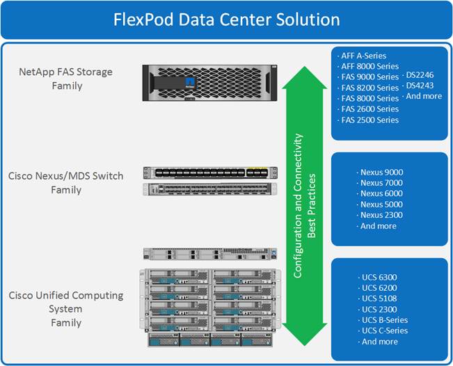
These components are connected and configured according to the best practices of both Cisco and NetApp to provide an ideal platform for running a variety of enterprise workloads with confidence. FlexPod can scale up for greater performance and capacity (adding compute, network, or storage resources individually as needed), or it can scale out for environments that require multiple consistent deployments (such as rolling out of additional FlexPod stacks). The reference architecture covered in this document leverages Cisco Nexus 9000 for the network switching element and pulls in the Cisco MDS 9000 for the SAN switching component.
One of the key benefits of FlexPod is its ability to maintain consistency during scale. Each of the component families shown (Cisco UCS, Cisco Nexus, and NetApp AFF) offers platform and resource options to scale the infrastructure up or down, while supporting the same features and functionality that are required under the configuration and connectivity best practices of FlexPod
SAN Architecture
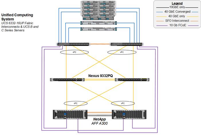
FlexPod Datacenter is a flexible architecture that can suit any customer requirement. It allows you to choose a SAN protocol based on personal preferences or hardware availability. This solution highlights a 40GbE iSCSI end-to-end deployment utilizing the Cisco Nexus 9332PQ and a 16Gb FC deployment utilizing the Cisco MDS 9148S. Both architectures use NFS volumes for generic virtual machine (VM) workloads and can optionally support 10 Gb Fiber Channel over Ethernet (FCoE). This design also supports 10Gb iSCSI and 8Gb FC architecture using the Cisco UCS 6248 Fabric Interconnect.
Design 1: End-to-End 40GbE iSCSI Architecture
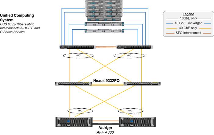
This design is suitable for customers who use IP based architecture in their datacenter, enabling them to upgrade to end-to-end 40GbE. The components used in this design are:
· NetApp AFF A300 storage controllers
- High Availability (HA) pair in switchless cluster configuration
- 40GbE adapter used in the expansion slot of each storage controller
- ONTAP 9.1
· Cisco Nexus 9332PQ switches
- Pair of switches in vPC configuration
· Cisco UCS 6332-16UP Fabric Interconnect
· 40Gb Unified Fabric
· Cisco UCS 5108 Chassis
- Cisco UCS 2304 IOM
- Cisco UCS B200 M4 servers with VIC 1340
- Cisco UCS C220 M4 servers with VIC 1385
Figure 2 illustrates the FlexPod Datacenter topology that supports the end-to-end 40GbE iSCSI design. The Cisco UCS 6300 Fabric Interconnect FlexPod Datacenter model enables a high-performance, low-latency, and lossless fabric supporting applications with these elevated requirements. The 40GbE compute and network fabric increases the overall capacity of the system while maintaining the uniform and resilient design of the FlexPod solution.
Figure 2 FlexPod Datacenter with Cisco UCS 6332-16UP Fabric Interconnects for end-to-end 40GbE iSCSI
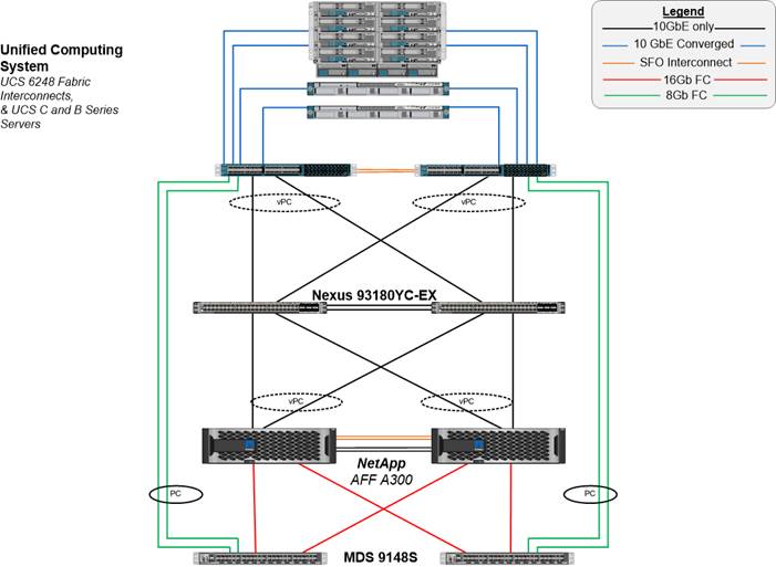
Design 2: 10GbE iSCSI Architecture
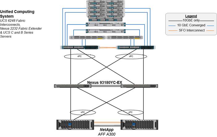
The components used in this design are:
· NetApp AFF A300 storage controllers
- HA pair in switchless cluster configuration
- Onboard 10GbE Unified Target Adapter 2 ports of each storage controller
- ONTAP 9.1
· Cisco Nexus 93180YC-EX switches
- Pair of switches in vPC configuration
· Cisco UCS 6248UP Fabric Interconnect
· 10Gb Unified Fabric
· Cisco UCS 5108 Chassis
- Cisco UCS 2204/2208 IOM
- Cisco UCS B200 M4 servers with VIC 1340
- Cisco UCS C220 M4 servers with VIC 1227
Figure 3 illustrates the FlexPod Datacenter topology that supports 10GbE iSCSI design. The Cisco UCS 6200 Fabric Interconnect FlexPod Datacenter model enables a high-performance, low-latency, and lossless fabric supporting applications with these elevated requirements. The 10GbE compute and network fabric increases the overall capacity of the system while maintaining the uniform and resilient design of the FlexPod solution.
Figure 3 FlexPod Datacenter with Cisco UCS 6248UP Fabric Interconnects for 10GbE iSCSI
Design 3: 16Gb FC Architecture
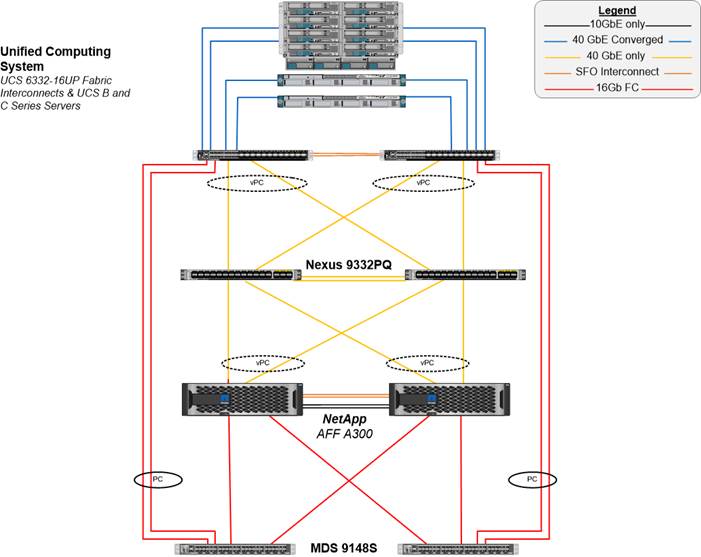
The components used in this design are:
· NetApp AFF A300 storage controllers
- HA pair in switchless cluster configuration
- Onboard 16G Unified Target Adapter 2 ports of each storage controller
- ONTAP 9.1
· Cisco Nexus 93180YC-EX switches
- Pair of switches in vPC configuration
· Cisco MDS 9148s
· Cisco UCS 6332-16UP Fabric Interconnect
· 40Gb Unified Fabric
· Cisco UCS 5108 Chassis
- Cisco UCS 2304 IOM
- Cisco UCS B200 M4 servers with VIC 1340
- Cisco UCS C220 M4 servers with VIC 1385
Figure 4 illustrates the FlexPod Datacenter topology that supports the 16 Gb FC design. The MDS provides 4/8/16G FC switching capability for the SAN boot of the Cisco UCS servers and for mapping of the FC application data disks. FC storage connects to the MDS at 16Gbps.
Figure 4 FlexPod Datacenter with Cisco UCS 6332-16UP Fabric Interconnects for 16G FC using MDS
Design 4: 8Gb FC architecture
The components used in this design are:
· NetApp AFF A300 storage controllers
- HA pair in switchless cluster configuration
- Onboard 16G Unified Target Adapter 2 ports of each storage controller
- ONTAP 9.1
· Cisco Nexus 93180YC-EX switches
- Pair of switches in vPC configuration
· Cisco MDS 9148s
- 16Gb connectivity between NetApp AFF A300 and MDS
- 8Gb connectivity between MDS and Cisco UCS 6248UP Fabric Interconnects
· Cisco UCS 6248UP Fabric Interconnect
· 10Gb Unified Fabric
· Cisco UCS 5108 Chassis
- Cisco UCS 2204/2208 IOM
- Cisco UCS B200 M4 servers with VIC 1340
- Cisco UCS C220 M4 servers with VIC 1385
Figure 5 illustrates the FlexPod Datacenter topology that supports the 8Gb FC design. The MDS provides 4/8/16G FC switching capability both for SAN boot of the Cisco UCS servers and for mapping of the FC application data disks. FC storage connects to the MDS at 16Gbps and FC compute connects to the MDS at 8Gbps. Additional links can be added to the SAN port channels between the MDS switches and Cisco UCS fabric interconnects to equalize the bandwidth throughout the solution.
Figure 5 FlexPod Datacenter with Cisco UCS 6248UP Fabric Interconnects for 8G FC using MDS
Design 5: 10Gb FCoE Architecture
![]() The 10Gb FCoE architecture is covered in Appendix of the FlexPod Datacenter with VMware vSphere 6.5, NetApp AFF A-Series and Fibre Channel Deployment Guide.
The 10Gb FCoE architecture is covered in Appendix of the FlexPod Datacenter with VMware vSphere 6.5, NetApp AFF A-Series and Fibre Channel Deployment Guide.
The components used in this design are:
· NetApp AFF A300 storage controllers
- HA pair in switchless cluster configuration
- Onboard 10G Unified Target Adapter 2 ports of each storage controller
- ONTAP 9.1
· Cisco Nexus 9332/93180YC-EX switches
- Pair of switches in vPC configuration
· Cisco UCS 6332-16UP/6248UP Fabric Interconnect
· Cisco UCS 5108 Chassis
- Cisco UCS 2304/2204/2208 IOM
- Cisco UCS B200 M4 servers with VIC 1340
- Cisco UCS C220 M4 servers with VIC 1385/1227
Figure 6 illustrates the FlexPod Datacenter topology that supports the 10Gb FCoE design. FCoE ports from storage are directly connected to the Cisco UCS Fabric Interconnects. Fiber channel zoning is done in the fabric interconnect, which is in fiber channel switching mode. Both the 6332-16UP (with 40 Gb IP-based storage) and 6248UP (with 10 Gb IP-based storage) are supported in this design. This design would also support FC connectivity between storage and the fabric interconnects.
Figure 6 FlexPod Datacenter with 10G FCoE using Direct Connect Storage
The following are some of the benefits and differences between iSCSI ,FC, and FCoE:
· SAN Boot choices
· Protocols used in tenant SVMs
NetApp A-Series All Flash FAS
With the new A-Series All Flash FAS (AFF) controller lineup, NetApp provides industry leading performance while continuing to provide a full suite of enterprise-grade data management and data protection features. The A-Series lineup offers double the IOPS, while decreasing the latency. The A-Series lineup includes the A200, A300, A700, and A700s. These controllers and their specifications listed in Table 1. For more information about the A-Series AFF controllers, see:
· http://www.netapp.com/us/products/storage-systems/all-flash-array/aff-a-series.aspx
· https://hwu.netapp.com/Controller/Index
Table 1 NetApp A-Series Controller Specifications
|
|
AFF A200 |
AFF A300 |
AFF A700 |
AFF A700s |
| NAS Scale-out |
2-8 nodes |
2-24 nodes |
2-24 nodes |
2-24 nodes |
| SAN Scale-out |
2-8 nodes |
2-12 nodes |
2-12 nodes |
2-12 nodes |
| Per HA Pair Specifications (Active-Active Dual Controller) |
||||
| Maximum SSDs |
144 |
384 |
480 |
216 |
| Maximum Raw Capacity |
2.2PB |
5.9PB |
7.3PB |
3.3PB |
| Effective Capacity |
8.8PB |
23.8PB |
29.7PB |
13PB |
| Chassis Form Factor |
2U chassis with two HA controllers and 24 SSD slots |
3U chassis with two HA controllers |
8u chassis with two HA controllers |
4u chassis with two HA controllers and 24 SSD slots |
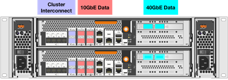
This solution utilizes the NetApp AFF A300, seen in Figure 7 and Figure 8. This controller provides the high performance benefits of 40GbE and all flash SSDs, offering better performance than the AFF8040, while taking up only 3U of rack space, versus 6U with the AFF8040. Combined with the disk shelf of 3.8TB disks, this solution can provide over ample horsepower and over 90TB of raw capacity, all while taking up only 5U of valuable rack space. This makes it an ideal controller for a shared workload converged infrastructure. For situations where more performance is needed, the A700s would be an ideal fit.
![]() The 40GbE cards are installed in the expansion slot 2 and the ports are e2a, e2e.
The 40GbE cards are installed in the expansion slot 2 and the ports are e2a, e2e.
Figure 7 NetApp A300 Front View

Figure 8 NetApp A300 Rear View
NetApp ONTAP 9.1
NetApp AFF Storage Design
This design leverages NetApp AFF A300 controllers deployed with ONTAP 9.1. The FlexPod storage design supports a variety of NetApp FAS controllers, including the AFF A-Series platforms, such as AFF8000, FAS9000, FAS8000, FAS2600 and FAS2500 products as well as legacy NetApp storage.
For more information about the AFF A-series product family, see: http://www.netapp.com/us/products/storage-systems/all-flash-array/aff-a-series.aspx.
Storage Efficiency
Storage efficiency has always been a primary architectural design point of ONTAP. A wide array of features allows businesses to store more data using less space. In addition to deduplication and compression, businesses can store their data more efficiently by using features such as unified storage, multi-tenancy, thin provisioning, and NetApp Snapshot® technology.
Starting with ONTAP 9, NetApp guarantees that the use of NetApp storage efficiency technologies on AFF systems reduce the total logical capacity used to store customer data by 75 percent, a data reduction ratio of 4:1. This space reduction is a combination of several different technologies, such as deduplication, compression, and compaction, which provide additional reduction to the basic features provided by ONTAP.
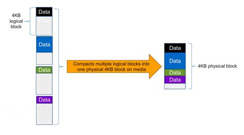
Compaction, which is introduced in ONTAP 9, is the latest patented storage efficiency technology released by NetApp. In the ONTAP WAFL file system, all I/O takes up 4KB of space, even if it does not actually require 4KB of data. Compaction combines multiple blocks that are not using their full 4KB of space together into one block. This one block can be more efficiently stored on the disk-to-save space. This process is illustrated in Figure 9.
RAID-TEC
With ONTAP 9, NetApp became the first storage vendor to introduce support for 15.3TB SSDs. These large drives dramatically reduce the physical space it takes for rack, power, and cool infrastructure equipment. Unfortunately, as drive sizes increase, so does the time it takes to reconstruct a RAID group after a disk failure. Although the NetApp RAID DP® storage protection technology offers much more protection than RAID 4, it is more vulnerable than usual to additional disk failure during reconstruction of a RAID group with larger disks.
To provide additional protection to RAID groups that contain large disk drives, ONTAP 9 introduces RAID with triple erasure encoding (RAID-TEC™). RAID-TEC provides a third parity disk in addition to the two that are present in RAID DP. This third parity disk offers additional redundancy to a RAID group, allowing up to three disks in the RAID group to fail. Because of the third parity drive present in RAID-TEC RAID groups, the size of the RAID group can be increased. Because of this increase in RAID group size, the percentage of a RAID group taken up by parity drives is no different than the percentage for a RAID DP aggregate.
RAID-TEC is available as a RAID type for aggregates made of any disk type or size. It is the default RAID type when creating an aggregate with SATA disks that are 6TB or larger, and it is the mandatory RAID type with SATA disks that are 10TB or larger, except when they are used in root aggregates. Most importantly, because of the WAFL format built into ONTAP, RAID-TEC provides the additional protection of a third parity drive without incurring a significant write penalty over RAID 4 or RAID DP.
For more information on RAID-TEC, see the Disks and Aggregates Power Guide, see https://library.netapp.com/ecm/ecm_download_file/ECMLP2496263.
Volume Encryption
Data security continues to be an important consideration for customers purchasing storage systems. NetApp has supported self-encrypting drives in storage clusters prior to ONTAP 9. However, in ONTAP 9, the encryption capabilities of ONTAP are extended by adding an Onboard Key Manager (OKM). The OKM generates stores the keys for each of the drives in ONTAP, allowing ONTAP to provide all functionality required for encryption out of the box. Through this functionality, sensitive data stored on disks is secure and can only be accessed by ONTAP.
In ONTAP 9.1, NetApp has extended the encryption capabilities further with NetApp Volume Encryption (NVE). NVE is a software-based mechanism for encrypting data. It allows a user to encrypt data at the per volume level instead of requiring encryption of all data in the cluster, thereby providing more flexibility and granularity to the ONTAP administrators. This encryption extends to Snapshot copies and FlexClone® volumes that are created in the cluster. One benefit of the NetApp Volume Encryption is that it executes after the implementation of the storage efficiency features and therefore doesn’t inhibit the ability of ONTAP to provide space savings to customers.
For more information about encryption in ONTAP 9.1, see the NetApp Encryption Power Guide:
https://library.netapp.com/ecm/ecm_download_file/ECMLP2572742
NetApp Storage Virtual Machine (SVM)
A cluster serves data through at least one and possibly multiple storage virtual machines (SVMs; formerly called Vservers). An SVM is a logical abstraction that represents the set of physical resources of the cluster. Data volumes and network logical interfaces (LIFs) are created and assigned to an SVM and may reside on any node in the cluster to which the SVM has been given access. An SVM may own resources on multiple nodes concurrently, and those resources can be moved nondisruptively from one node to another. For example, a flexible volume can be nondisruptively moved to a new node and aggregate, or a data LIF can be transparently reassigned to a different physical network port. The SVM abstracts the cluster hardware and it is not tied to any specific physical hardware.
An SVM can support multiple data protocols concurrently. Volumes within the SVM can be joined together to form a single NAS namespace, which makes all of an SVM's data available through a single share or mount point to NFS and CIFS clients. SVMs also support block-based protocols, and LUNs can be created and exported by using iSCSI, FC, or FCoE. Any or all of these data protocols can be configured for use within a given SVM.
Because it is a secure entity, an SVM is only aware of the resources that are assigned to it and has no knowledge of other SVMs and their respective resources. Each SVM operates as a separate and distinct entity with its own security domain. Tenants can manage the resources allocated to them through a delegated SVM administration account. Each SVM can connect to unique authentication zones such as Active Directory, LDAP, or NIS. A NetApp cluster can contain multiple SVMs. If you have multiple SVMs, you can delegate an SVM to a specific application. This allows administrators of the application to access only the dedicated SVMs and associated storage, increasing manageability, and reducing risk.
SAN Boot
NetApp recommends implementing SAN boot for Cisco UCS servers in the FlexPod Datacenter solution. Doing so enables the operating system to be safely secured by the NetApp All Flash FAS storage system, providing better performance. In this design, both iSCSI and FC SAN boot are validated.
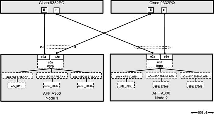
In iSCSI SAN boot, each UCS server is assigned two iSCSI vNICs (one for each SAN fabric) that provide redundant connectivity all the way to the storage. The 40G Ethernet storage ports, in this example e2a and e2e, which are connected to the Nexus switches are grouped together to form one logical port called an interface group (igroup) (in this example, a0a). The iSCSI VLANs are created on the igroup and the iSCSI logical interfaces (LIFs) are created on iSCSI port groups (in this example, a0a-<iSCSI-A-VLAN>). The iSCSI boot LUN is exposed to the servers through the iSCSI LIF using igroups; this enables only the authorized server to have access to the boot LUN. Refer to Figure 10 for the port and LIF layout.
Figure 10 iSCSI - SVM Ports and LIF Layout

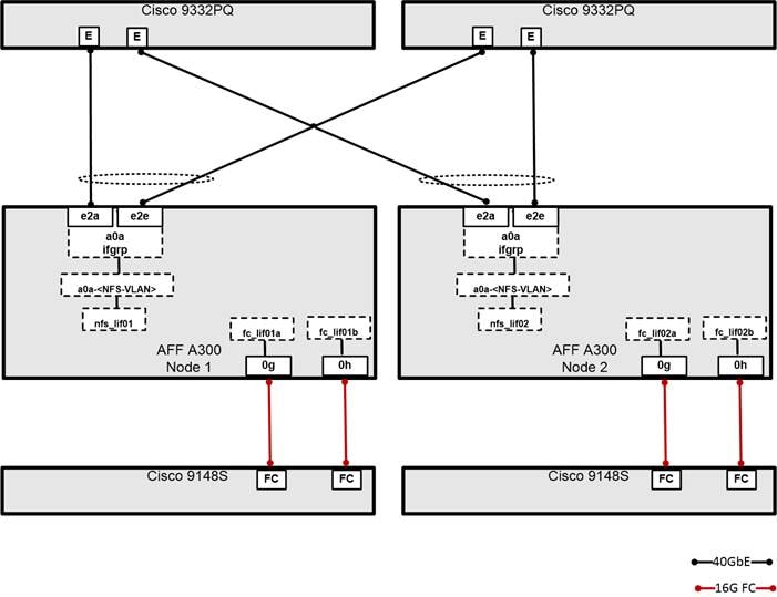
In FC SAN boot, each Cisco UCS server boots by connecting the NetApp All Flash FAS storage to the Cisco MDS switch. The 16G FC storage ports, in this example 0g and 0h, are connected to Cisco MDS switch. The FC LIFs are created on the physical ports and each FC LIF is uniquely identified by its target WWPN. The storage system target WWPNs can be zoned with the server initiator WWPNs in the Cisco MDS switches. The FC boot LUN is exposed to the servers through the FC LIF using the MDS switch; this enables only the authorized server to have access to the boot LUN. Refer Figure 10 for the port and LIF layout
Figure 11 FC - SVM ports and LIF layout

Unlike NAS network interfaces, the SAN network interfaces are not configured to fail over during a failure. Instead if a network interface becomes unavailable, the host chooses a new optimized path to an available network interface. ALUA is a standard supported by NetApp used to provide information about SCSI targets, which allows a host to identify the best path to the storage.
iSCSI and FC: Network and Storage Connectivity
In the iSCSI design, the storage controllers 40GbE ports are directly connected to Cisco Nexus 9332PQ switches. Each controller is equipped with 40GbE cards on the expansion slot 2 that has two physical ports. Each storage controller is connected to two SAN fabrics. This method provides increased redundancy to make sure that the paths from the host to its storage LUNs are always available. Figure 12 shows the port and interface assignments connection diagram for the AFF storage to the Cisco Nexus 9332PQ SAN fabrics. This FlexPod design uses the following port and interface assignments. In this design, NFS and iSCSI traffic utilize the 40G bandwidth.
FC Connectivity
In the FC design, the storage controller is connected to a Cisco MDS SAN switching infrastructure for FC boot and Cisco Nexus 9332PQ for all Ethernet traffic. Although smaller configurations can make use of the direct-attached, FC/FCoE storage method of the Cisco UCS fabric interconnect, the Cisco MDS provides increased scalability for larger configurations with multiple Cisco UCS domains and the ability to connect to a data center SAN. An ONTAP storage controller uses N_Port ID virtualization (NPIV) to allow each network interface to log into the FC fabric using a separate worldwide port name (WWPN). This allows a host to communicate with an FC target network interface, regardless of where that network interface is placed. Use the show npiv status command on your MDS switch to ensure that NPIV is enabled. Each controller is equipped with onboard CNA ports that can operate in 10GbE or 16G FC. For the FC design, the onboard ports are modified to FC target mode and the ports are connected to two SAN fabrics. This method provides increased redundancy to make sure that the paths from the host to its storage LUNs are always available. Figure 13 shows the port and interface assignments connection diagram for the AFF storage to the Cisco MDS SAN fabrics. This FlexPod design uses the following port and interface assignments. In this design, NFS utilizes 40G and FC utilizes the 16G bandwidth.
Figure 13 Port and Interface Assignments
Distributed Switch Options Virtual Switching
FlexPod uses a VMware Virtual Distributed Switch(vDS) for primary virtual switching, with additional Cisco UCS Virtual Network Interface Cards (vNIC) created when using iSCSI boot in the deployment as shown below in Figure 14.
Figure 14 Compact vNIC design with iSCSI vSwitches
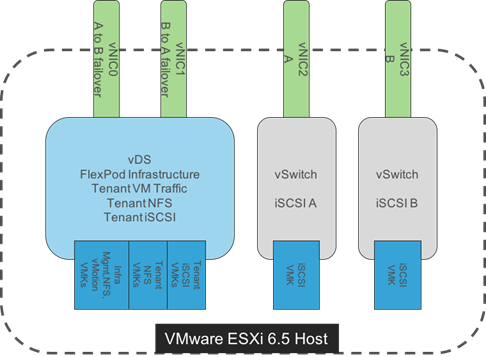
For the iSCSI based implementation, iSCSI interfaces used for SAN boot of the ESXi server will need to be presented as native VLANs on dedicated vNICs that are connected with standard vSwitches.
Within the vDS, NFS and VM Traffic port groups are left with the default NIC Teaming options, but management and vMotion VMkernels are instead setup with active/standby teaming within their port groups. For vMotion, it has been setup with vNIC1 (B side of the fabric) as active, and vNIC0 (A side of the fabric) as standby to contain vMotion, and management setup in the alternate layout with vNIC0 active and vNIC1 set as standby. This allows traffic from vMotion and management to be contained within one side of the fabric interconnect and to prevent it from hair-pinning up through the upstream Nexus switch if the differing hosts were allowed to randomly choose between the two fabrics.
Tenant vDSs can be deployed with dedicated vNIC uplinks as shown in Figure 15, allowing for RBAC of the visibility and/or adjustment of the vDS to the respective tenant manager in vCenter. Tenant networks do not have a requirement to exist in separate vDS, and can optionally be pulled into a compact design that was used in the validation of this FlexPod release.
In previous FlexPod architectures that utilized VMware vDS, the ESXi management VMkernel port, the Infrastructure NFS VMkernel port, and iSCSI VMkernel ports were left on standard vSwitches and not transitioned to the VMware vDS as they are in this architecture with vSphere 6.5. This was because the local vDS software on each ESXi host in previous releases of VMware did not retain its configuration and had to obtain this configuration from vCenter after booting. Testing with the vSphere 6.5 version of vDS showed that the local vDS software did retain its configuration over reboots and all network interfaces could safely be transitioned to the vDS.
Figure 15 Compact vNIC Design Extended for Dedicated Tenant vNICs
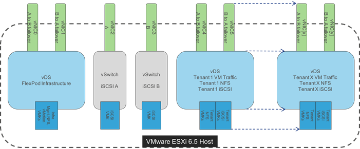
In the Fibre Channel based deployments, the iSCSI vNICs, iSCSI VMKs, and corresponding vSwitches would not be present.
Cisco Nexus
Cisco Nexus series switches provide an Ethernet switching fabric for communications between the Cisco UCS, NetApp storage controllers, and the rest of a customer’s network. There are many factors to take into account when choosing the main data switch in this type of architecture to support both the scale and the protocols required for the resulting applications. All Nexus switch models including the Nexus 5000 and Nexus 7000 are supported in this design, and may provide additional features such as FCoE or OTV. However, be aware that there may be slight differences in setup and configuration based on the switch used. The validation for the 40GbE iSCSI deployment leverages the Cisco Nexus 9000 series switches, which deliver high performance 40GbE ports, density, low latency, and exceptional power efficiency in a broad range of compact form factors.
Many of the most recent single-site FlexPod designs also use this switch due to the advanced feature set and the ability to support Application Centric Infrastructure (ACI) mode. When leveraging ACI fabric mode, the Nexus 9000 series switches are deployed in a spine-leaf architecture. Although the reference architecture covered in this design does not leverage ACI, it lays the foundation for customer migration to ACI in the future, and fully supports ACI today if required.
For more information, refer to http://www.cisco.com/c/en/us/products/switches/nexus-9000-series-switches/index.html
This FlexPod design deploys a single pair of Nexus 9000 top-of-rack switches within each placement, using the traditional standalone mode running NX-OS.
The traditional deployment model delivers numerous benefits for this design:
· High performance and scalability with L2 and L3 support per port (Up to 60Tbps of non-blocking performance with less than 5 microsecond latency)
· Layer 2 multipathing with all paths forwarding through the Virtual port-channel (vPC) technology
· VXLAN support at line rate
· Advanced reboot capabilities include hot and cold patching
· Hot-swappable power-supply units (PSUs) and fans with N+1 redundancy
Cisco Nexus 9000 provides Ethernet switching fabric for communications between the Cisco UCS domain, the NetApp storage system and the enterprise network. In the FlexPod design, Cisco UCS Fabric Interconnects and NetApp storage systems are connected to the Cisco Nexus 9000 switches using virtual PortChannels (vPC)
Virtual Port Channel (vPC)
A virtual PortChannel (vPC) allows links that are physically connected to two different Cisco Nexus 9000 Series devices to appear as a single PortChannel. In a switching environment, vPC provides the following benefits:
· Allows a single device to use a PortChannel across two upstream devices
· Eliminates Spanning Tree Protocol blocked ports and use all available uplink bandwidth
· Provides a loop-free topology
· Provides fast convergence if either one of the physical links or a device fails
· Helps ensure high availability of the overall FlexPod system
Figure 16 Cisco Nexus 9000 Connections
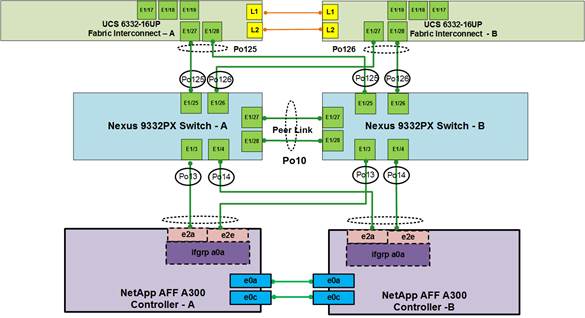
Figure 16 shows the connections between Cisco Nexus 9000, UCS Fabric Interconnects and NetApp AFF A300. vPC requires a “peer link” which is documented as port channel 10 in this diagram. In addition to the vPC peer-link, the vPC peer keepalive link is a required component of a vPC configuration. The peer keepalive link allows each vPC enabled switch to monitor the health of its peer. This link accelerates convergence and reduces the occurrence of split-brain scenarios. In this validated solution, the vPC peer keepalive link uses the out-of-band management network. This link is not shown in Figure 16.
Cisco Nexus 9000 Best Practices
Cisco Nexus 9000 related best practices used in the validation of the FlexPod architecture are summarized below:
Cisco Nexus 9000 Features Enabled
· Link Aggregation Control Protocol (LACP part of 802.3ad)
· Cisco Virtual Port Channeling (vPC) for link and device resiliency
· Cisco Discovery Protocol (CDP) for infrastructure visibility and troubleshooting
vPC Considerations
· Define a unique domain ID
· Set the priority of the intended vPC primary switch lower than the secondary (default priority is 32768)
· Establish peer keepalive connectivity. It is recommended to use the out-of-band management network (mgmt0) or a dedicated switched virtual interface (SVI)
· Enable vPC auto-recovery feature
· Enable peer-gateway. Peer-gateway allows a vPC switch to act as the active gateway for packets that are addressed to the router MAC address of the vPC peer allowing vPC peers to forward traffic
· Enable IP ARP synchronization to optimize convergence across the vPC peer link.
· A minimum of two 10 Gigabit Ethernet connections are required for vPC
· All port channels should be configured in LACP active mode
Spanning Tree Considerations
· The spanning tree priority was not modified. Peer-switch (part of vPC configuration) is enabled which allows both switches to act as root for the VLANs
· Loopguard is disabled by default
· BPDU guard and filtering are enabled by default
· Bridge assurance is only enabled on the vPC Peer Link.
· Ports facing the NetApp storage controller and UCS are defined as “edge” trunk ports
For configuration details, refer to the Cisco Nexus 9000 Series Switches Configuration guides: http://www.cisco.com/c/en/us/support/switches/nexus-9000-series-switches/products-installation-and-configuration-guides-list.html
Bringing Together 40Gb End-to-End
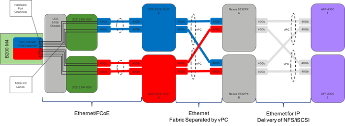
The Cisco Nexus 9000 is the key component bringing together the 40Gb capabilities of the other pieces of this design. vPCs extend to both the AFF A300 Controllers and the Cisco UCS 6332-16UP Fabric Interconnects. Passage of this traffic shown in Figure 17 going from left to right is as follows:
· Coming from the Cisco UCS B200 M4 server, equipped with a VIC 1340 adapter and a Port Expander card, allowing for 40Gb on each side of the fabric (A/B) into the server.
· Pathing through 10Gb KR lanes of the Cisco UCS 5108 Chassis backplane into the Cisco UCS 2304 IOM (Fabric Extender).
· Connecting from each IOM to the Fabric Interconnect with pairs of 40Gb uplinks automatically configured as port channels during chassis association.
· Continuing from the Cisco UCS 6332-16UP Fabric Interconnects into the Cisco Nexus 9332PX with a bundle of 40Gb ports presenting each side of the fabric from the Nexus pair as a common switch using a vPC.
· Ending at the AFF A 300 Controllers with 40Gb bundled vPCs from the Nexus switches now carrying both sides of the fabric.
Figure 17 vPC, AFF A300 Controllers, and Cisco UCS 6332-16UP Fabric Interconnect Traffic
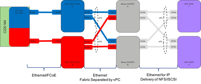
The equivalent view for a Cisco UCS C-Series server is shown in Figure 18 below, which uses the same primary connectivity provided by the Cisco Nexus switches, but will not go through Cisco UCS 2304 IOM and Cisco UCS 5108 Chassis:
Cisco MDS
The Cisco® MDS 9148S 16G Multilayer Fabric Switch is the next generation of the highly reliable, flexible, and low-cost Cisco MDS 9100 Series switches. It combines high performance with exceptional flexibility and cost effectiveness. This powerful, compact one rack-unit (1RU) switch scales from 12 to 48 line-rate 16 Gbps Fibre Channel ports. The Cisco MDS 9148S delivers advanced storage networking features and functions with ease of management and compatibility with the entire Cisco MDS 9000 Family portfolio for reliable end-to-end connectivity.
For more information on the MDS 9148S please see the product data sheet at: http://www.cisco.com/c/en/us/products/collateral/storage-networking/mds-9148s-16g-multilayer-fabric-switch/datasheet-c78-731523.html
MDS Insertion into FlexPod
The MDS 9148S is inserted into the FlexPod design to provide Fibre Channel switching between the NetApp AFF A300 controllers, and Cisco UCS managed B-Series and C-Series servers connected to the Cisco UCS 6332-16UP and Cisco UCS 6248UP Fabric Interconnects. Adding the MDS to the FlexPod infrastructure allows for:
· Increased scaling of both the NetApp storage and the Cisco UCS compute resources
· Large range of existing models supported from the 9100, 9200, 9300, and 9700 product lines
· A dedicated network for storage traffic
· Increased tenant separation
· Deployments utilizing existing qualified SAN switches that might be within the customer environment
FC and FCoE direct attached (the latter covered in the Appendix of the FlexPod Datacenter with VMware vSphere 6.5, NetApp AFF A-Series and Fibre Channel Deployment Guide) are configurable for FlexPods, using the UCS Fabric Interconnects for the SAN switching. This model will not require an MDS, but will have reduced scaling capacity, and have limited options for extending SAN resources outside of the FlexPod to elsewhere in the customer data center.
Smart Zoning with MDS
Configuration of the Cisco MDS within this FlexPod design takes advantage of Smart Zoning to increase zoning efficiency within the MDS. Smart Zoning allows for reduced TCAM (ternary content addressable memory) entries, which are fabric ACL entries of the MDS allowing traffic between targets and initiators. When calculating TCAMs used, two TCAM entries will be created for each connection of devices within the zone. Without Smart Zoning enabled for a zone, targets will have a pair of TCAMs established between each other, and all initiators will additionally have a pair of TCAMs established to other initiators in the zone as shown in Figure 19 below:
Figure 19 Smart Zoning with MDS
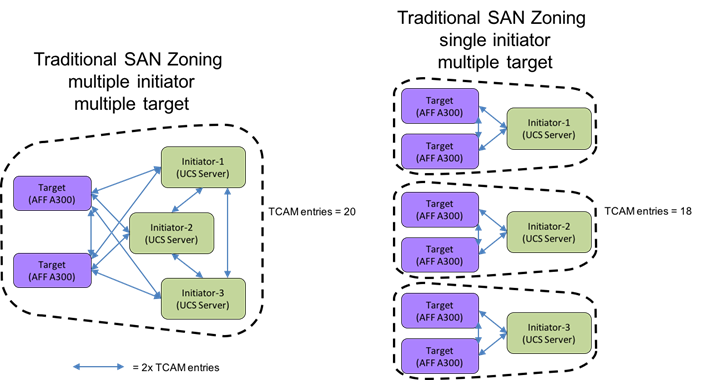
Using Smart Zoning, Targets and Initiators are identified, reducing TCAMs needed to only occur Target to Initiator within the zone as shown in Figure 20:
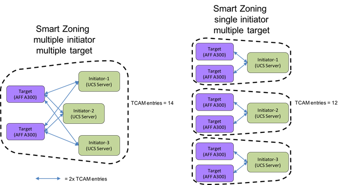
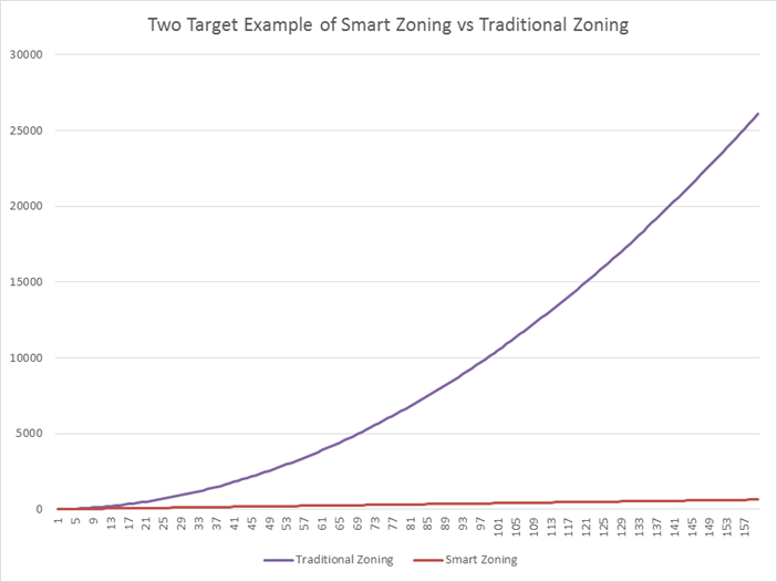
Within the traditional zoning model for a multiple initiator, multiple target zone shown in the first diagram set of Figure 19, the TCAM entries will grow rapidly, representing a relationship of TCAMs = (T+I)*(T+I)-1) where T = targets and I = initiators. For Smart Zoning configuration, this same multiple initiator, multiple target zone shown in the second diagram set of Figure 20 will instead have TCAMs = 2*T*I where T = targets and I = initiators. This exponential difference can be seen for the traditional zoning on the graph below showing the example maximum 160 initiators of servers configurable to a single UCS zone connecting to 2 targets represented by a pair of NetApp controllers.
For more information on Smart Zoning, see: http://www.cisco.com/c/en/us/td/docs/switches/datacenter/mds9000/sw/7_3/configuration/fabric/fabric/zone.html#81500
End-to-End Design with MDS
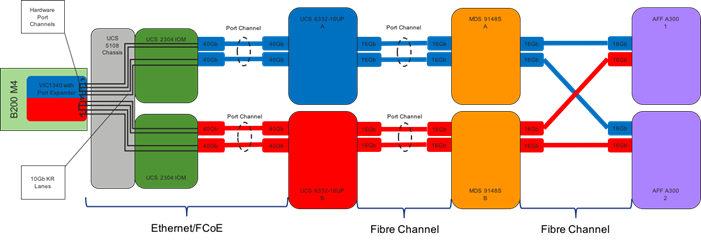
The End-to-End storage network design with the MDS will look similar to the 40Gb End-to-End design seen with the Nexus 9300 switches. For the Cisco UCS 6332-16UP based implementation connecting to a Cisco UCS B-Series server, the view of the design shown in Figure 21 can be seen starting from the left as:
· Coming from the Cisco UCS B200 M4 server, equipped with a VIC 1340 adapter and a Port Expander card, allowing for the potential of 40Gb on each side of the fabric (A/B) into the server, the FC traffic is encapsulated as FCoE and is sent along the common fabric with the network traffic.
· Pathing through 10Gb KR lanes of the Cisco UCS 5108 Chassis backplane into the Cisco UCS 2304 IOM (Fabric Extender).
· Connecting from each IOM to the Cisco UCS 6332-16UP Fabric Interconnects with pairs of 40Gb uplinks automatically configured as port channels during chassis association.
· The Fabric Interconnects will connect to the MDS switches with port channels using a pair of 16Gb uplinks from each fabric side sending the FC traffic.
· Ending at the AFF A300 Controllers with 16Gb Fibre Channel connections coming from each MDS, connecting into each AFF A300 controller.
Figure 21 End-to-End Design with MDS
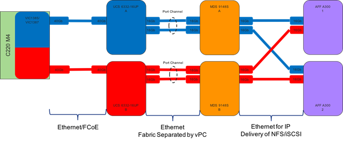
The equivalent view for a Cisco UCS C-Series server is shown in Figure 22, which uses the same primary connectivity provided by the MDS Switches, but will not go through Cisco UCS 2304 IOM and Cisco UCS 5108 Chassis.
Figure 22 End-to-End Design with Cisco UCS C-Series Server
Cisco Unified Computing System
Cisco UCS 6300 and UCS 6200 Fabric Interconnects
The Cisco UCS Fabric interconnects provide a single point for connectivity and management for the entire system. Typically deployed as an active-active pair, the system’s fabric interconnects integrate all components into a single, highly-available management domain controlled by Cisco UCS Manager. The fabric interconnects manage all I/O efficiently and securely at a single point, resulting in deterministic I/O latency regardless of a server or virtual machine’s topological location in the system.
The Fabric Interconnect provides both network connectivity and management capabilities for the Cisco UCS system. IOM modules in the blade chassis support power supply, along with fan and blade management. They also support port channeling and, thus, better use of bandwidth. The IOMs support virtualization-aware networking in conjunction with the Fabric Interconnects and Cisco Virtual Interface Cards (VIC).
FI 6300 Series and IOM 2304 provide a few key advantages over the existing products. FI 6300 Series and IOM 2304 support 40GbE / FCoE port connectivity that enables an end-to-end 40GbE / FCoE solution. Unified ports support 4/8/16G FC ports for higher density connectivity to SAN ports.
Table 2 Key Differences Between FI 6200 Series and FI 6300 Series
| FI 6200 Series |
FI 6300 Series |
|||
| Features |
6248 |
6296 |
6332 |
6332-16UP |
| Max 10G ports |
48 |
96 |
96* + 2** |
72* + 16 |
| Max 40G ports |
- |
- |
32 |
24 |
| Max unified ports |
48 |
96 |
- |
16 |
| Max FC ports |
48 x 2/4/8G FC |
96 x 2/4/8G FC |
- |
16 x 4/8/16G FC |
* Using 40G to 4x10G breakout cables
** Requires QSA module
Cisco UCS Differentiators
Cisco’s Unified Computing System is revolutionizing the way servers are managed in datacenter. The following are the unique differentiators of Cisco Unified Computing System and Cisco UCS Manager.
· Embedded Management — In Cisco UCS, the servers are managed by the embedded firmware in the Fabric Interconnects, eliminating need for any external physical or virtual devices to manage the servers.
· Unified Fabric — In Cisco UCS, from blade server chassis or rack servers to FI, there is a single Ethernet cable used for LAN, SAN and management traffic. This converged I/O results in reduced cables, SFPs and adapters – reducing capital and operational expenses of overall solution.
· Auto Discovery — By simply inserting the blade server in the chassis or connecting rack server to the fabric interconnect, discovery and inventory of compute resource occurs automatically without any management intervention. The combination of unified fabric and auto-discovery enables the wire-once architecture of Cisco UCS, where compute capability of Cisco UCS can be extended easily while keeping the existing external connectivity to LAN, SAN and management networks.
· Policy Based Resource Classification — Once a compute resource is discovered by Cisco UCS Manager, it can be automatically classified to a given resource pool based on policies defined. This capability is useful in multi-tenant cloud computing. This CVD showcases the policy based resource classification of Cisco UCS Manager.
· Combined Rack and Blade Server Management — Cisco UCS Manager can manage Cisco UCS B-series blade servers and Cisco UCS C-series rack server under the same Cisco UCS domain. This feature, along with stateless computing makes compute resources truly hardware form factor agnostic.
· Model based Management Architecture — Cisco UCS Manager architecture and management database is model based and data driven. An open XML API is provided to operate on the management model. This enables easy and scalable integration of Cisco UCS Manager with other management systems.
· Policies, Pools, Templates — The management approach in Cisco UCS Manager is based on defining policies, pools and templates, instead of cluttered configuration, which enables a simple, loosely coupled, data driven approach in managing compute, network and storage resources.
· Loose Referential Integrity — In Cisco UCS Manager, a service profile, port profile or policies can refer to other policies or logical resources with loose referential integrity. A referred policy cannot exist at the time of authoring the referring policy or a referred policy can be deleted even though other policies are referring to it. This provides different subject matter experts to work independently from each-other. This provides great flexibility where different experts from different domains, such as network, storage, security, server and virtualization work together to accomplish a complex task.
· Policy Resolution — In Cisco UCS Manager, a tree structure of organizational unit hierarchy can be created that mimics the real life tenants and/or organization relationships. Various policies, pools and templates can be defined at different levels of organization hierarchy. A policy referring to another policy by name is resolved in the organization hierarchy with closest policy match. If no policy with specific name is found in the hierarchy of the root organization, then special policy named “default” is searched. This policy resolution practice enables automation friendly management APIs and provides great flexibility to owners of different organizations.
· Service Profiles and Stateless Computing — A service profile is a logical representation of a server, carrying its various identities and policies. This logical server can be assigned to any physical compute resource as far as it meets the resource requirements. Stateless computing enables procurement of a server within minutes, which used to take days in legacy server management systems.
· Built-in Multi-Tenancy Support — The combination of policies, pools and templates, loose referential integrity, policy resolution in organization hierarchy and a service profiles based approach to compute resources makes Cisco UCS Manager inherently friendly to multi-tenant environment typically observed in private and public clouds.
· Extended Memory — The enterprise-class Cisco UCS B200 M4 blade server extends the capabilities of Cisco’s Unified Computing System portfolio in a half-width blade form factor. The Cisco UCS B200 M4 harnesses the power of the latest Intel® Xeon® E5-2600 v4 Series processor family CPUs with up to 1536 GB of RAM (using 64 GB DIMMs) – allowing huge VM to physical server ratio required in many deployments, or allowing large memory operations required by certain architectures like big data.
· Virtualization Aware Network — Cisco VM-FEX technology makes the access network layer aware about host virtualization. This prevents domain pollution of compute and network domains with virtualization when virtual network is managed by port-profiles defined by the network administrators’ team. VM-FEX also off-loads hypervisor CPU by performing switching in the hardware, thus allowing hypervisor CPU to do more virtualization related tasks. VM-FEX technology is well integrated with VMware vCenter, Linux KVM and Hyper-V SR-IOV to simplify cloud management.
· Simplified QoS — Even though Fibre Channel and Ethernet are converged in Cisco UCS fabric, built-in support for QoS and lossless Ethernet makes it seamless. Network Quality of Service (QoS) is simplified in Cisco UCS Manager by representing all system classes in one GUI panel.
Cisco UCS Design Options within this FlexPod
Cisco UCS vNICs
Cisco UCS vNIC templates in the FlexPod architecture, other than those used for iSCSI vNICs, are set with failover enabled to allow for hardware resolution of an uplink loss from the fabric interconnect. Settling the failover at the hardware layer gives a faster resolution to uplink loss in a disruption of the fabric interconnect than would occur from polling by the vSwitch or vDS.
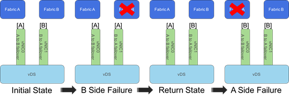
This failover makes the active/standby configuration for vNICs redundant as the standby uplink will not be called on within the vDS, but the presence of the standby uplink within the configuration will avert an uplink redundancy missing alarm within vCenter.
Cisco Unified Computing System Chassis/FEX Discovery Policy
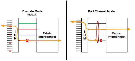
Cisco UCS can be configured to discover a chassis using Discrete Mode or the Port-Channel mode (Figure 23). In Discrete Mode each FEX KR connection and therefore server connection is tied or pinned to a network fabric connection homed to a port on the Fabric Interconnect. In the presence of a failure on the external “link” all KR connections are disabled within the FEX I/O module. In Port-Channel mode, the failure of a network fabric link allows for redistribution of flows across the remaining port channel members. Port-Channel mode therefore is less disruptive to the fabric and hence recommended in the FlexPod designs.
Figure 23 Chassis Discover Policy - Discrete Mode vs. Port Channel Mode
Cisco Unified Computing System – QoS and Jumbo Frames
FlexPod accommodates a myriad of traffic types (vMotion, NFS, FCoE, control traffic, etc.) and is capable of absorbing traffic spikes and protect against traffic loss. Cisco UCS and Nexus QoS system classes and policies deliver this functionality. In this validation effort the FlexPod was configured to support jumbo frames with an MTU size of 9000. Enabling jumbo frames allows the FlexPod environment to optimize throughput between devices while simultaneously reducing the consumption of CPU resources.
![]() When setting up Jumbo frames, it is important to make sure MTU settings are applied uniformly across the stack to prevent packet drops and negative performance.
When setting up Jumbo frames, it is important to make sure MTU settings are applied uniformly across the stack to prevent packet drops and negative performance.
Cisco UCS Physical Connectivity
Cisco UCS Fabric Interconnects are configured with two port-channels, one from each FI, to both Cisco Nexus 9000s and 16Gbps to the corresponding MDS 9148s switch. The fibre channel connections carry the fibre channel boot and data LUNs from the A and B fabrics to each of the MDS switches which then connect to the storage controllers. The port-channels carry the remaining data and storage traffic originated on the Cisco Unified Computing System. The validated design utilized two uplinks from each FI to the Nexus switches to create the port-channels, for an aggregate bandwidth of 160GbE (4 x 40GbE) with the 6332-16UP. The number of links can be easily increased based on customer data throughput requirements.
Cisco Unified Computing System – C-Series Server Design
Cisco UCS Manager 3.1 provides two connectivity modes for Cisco UCS C-Series Rack-Mount Server management. Starting in Cisco UCS Manager release version 2.2 an additional rack server management mode using Network Controller Sideband Interface (NC-SI). Cisco UCS VIC 1385 Virtual Interface Card (VIC) uses the NC-SI, which can carry both data traffic and management traffic on the same cable. Single-wire management allows for denser server to FEX deployments.
For configuration details refer to the Cisco UCS configuration guides at:
VMware vSphere 6.5
VMware vSphere is a virtualization platform for holistically managing large collections of infrastructure (resources-CPUs, storage and networking) as a seamless, versatile, and dynamic operating environment. Unlike traditional operating systems that manage an individual machine, VMware vSphere aggregates the infrastructure of an entire data center to create a single powerhouse with resources that can be allocated quickly and dynamically to any application in need.
vSphere 6.5 brings a number of improvements including, but not limited to:
· Added native features to the vCenter Server Appliance
· vSphere Web Client and fully supported HTML-5 client
· VM Encryption and Encrypted vMotion
· Improvements to DR
For more information on VMware vSphere and its components, refer to:
http://www.vmware.com/products/vsphere.html
vSphere vSwitch to vDS
The VMware vDS in this release of VMware vSphere has shown reliability not present in previous vDS releases, leading this FlexPod design to bring host management VMkernels and the vCenter network interface into the vDS that is hosted from the vCenter.
There is still some care required in the step by step deployment to avoid isolating the vCenter when migrating the vCenter over from a vSwitch to a vDS hosted by the vCenter as shown in Figure 24.
Figure 24 vCenter migration from vSwitch to vDS

vCenter will maintain connectivity during this migration as detailed in the FlexPod Datacenter with VMware vSphere 6.5, NetApp AFF A-Series and Fibre Channel Deployment Guide. This is a requirement in FlexPods hosting their own vCenter, and not steps required when the vCenter is on a separate management cluster.
A high-level summary of the FlexPod Datacenter Design validation is provided in this section. The solution was validated for basic data forwarding by deploying virtual machines running the IOMeter tool. The system was validated for resiliency by failing various aspects of the system under load. Examples of the types of tests executed include:
· Failure and recovery of FC booted ESXi hosts in a cluster
· Rebooting of FC booted hosts
· Service Profile migration between blades
· Failure of partial and complete IOM links
· Failure and recovery of FC paths to AFF nodes, MDS switches, and fabric interconnects
· SSD removal to trigger an aggregate rebuild
· Storage link failure between one of the AFF nodes and the Cisco MDS
· Load was generated using the IOMeter tool and different IO profiles were used to reflect the different profiles that are seen in customer networks
Validated Hardware and Software
Table 3 describes the hardware and software versions used during solution validation. It is important to note that Cisco, NetApp, and VMware have interoperability matrixes that should be referenced to determine support for any specific implementation of FlexPod. Click the following links for more information:
· NetApp Interoperability Matrix Tool: http://support.netapp.com/matrix/
· Cisco UCS Hardware and Software Interoperability Tool: http://www.cisco.com/web/techdoc/ucs/interoperability/matrix/matrix.html
· VMware Compatibility Guide: http://www.vmware.com/resources/compatibility/search.php
Table 3 Validated Software Versions
| Layer |
Device |
Image |
Comments |
| Compute |
Cisco UCS Fabric Interconnects 6300 Series and 6200 Series, UCS B-200 M4, UCS C-220 M4 |
3.1(2f) |
|
| Network |
Cisco Nexus 9000 NX-OS |
7.0(3) I4(5) |
|
| Storage |
NetApp AFF A300 |
NetApp ONTAP 9.1 |
|
|
|
Cisco MDS 9148S |
7.3(1)D1(1) |
|
| Software |
Cisco UCS Manager |
3.1(2f) |
|
|
|
Cisco UCS Manager Plugin for VMware vSphere
|
2.0.1 |
|
|
|
VMware vSphere ESXi |
6.5a Build 4887370 |
|
|
|
VMware vCenter |
6.5a Build 4944578 |
|
|
|
NetApp Virtual Storage Console (VSC) |
6.2.1P1 |
|
FlexPod Datacenter with VMware vSphere 6.5 is the optimal shared infrastructure foundation to deploy a variety of IT workloads that is future proofed with 16 Gb/s FC or 40Gb/s iSCSI, with either delivering 40Gb Ethernet connectivity. Cisco and NetApp have created a platform that is both flexible and scalable for multiple use cases and applications. From virtual desktop infrastructure to SAP®, FlexPod can efficiently and effectively support business-critical applications running simultaneously from the same shared infrastructure. The flexibility and scalability of FlexPod also enable customers to start out with a right-sized infrastructure that can ultimately grow with and adapt to their evolving business requirements.
Products and Solutions
Cisco Unified Computing System:
http://www.cisco.com/en/US/products/ps10265/index.html
Cisco UCS 6300 Series Fabric Interconnects:
Cisco UCS 5100 Series Blade Server Chassis:
http://www.cisco.com/en/US/products/ps10279/index.html
Cisco UCS B-Series Blade Servers:
http://www.cisco.com/en/US/partner/products/ps10280/index.html
Cisco UCS C-Series Rack Mount Servers:
http://www.cisco.com/c/en/us/products/servers-unified-computing/ucs-c-series-rack-servers/index.html
Cisco UCS Adapters:
http://www.cisco.com/en/US/products/ps10277/prod_module_series_home.html
Cisco UCS Manager:
http://www.cisco.com/en/US/products/ps10281/index.html
Cisco UCS Manager Plug-in for VMware vSphere Web Client:
Cisco Nexus 9000 Series Switches:
http://www.cisco.com/c/en/us/products/switches/nexus-9000-series-switches/index.html
Cisco MDS 9000 Multilayer Fabric Switches:
VMware vCenter Server:
http://www.vmware.com/products/vcenter-server/overview.html
VMware vSphere:
https://www.vmware.com/products/vsphere
NetApp ONTAP 9:
http://www.netapp.com/us/products/platform-os/ontap/index.aspx
NetApp AFF A300:
http://www.netapp.com/us/products/storage-systems/all-flash-array/aff-a-series.aspx
NetApp OnCommand:
http://www.netapp.com/us/products/management-software/
NetApp VSC:
http://www.netapp.com/us/products/management-software/vsc/
NetApp SnapManager:
http://www.netapp.com/us/products/management-software/snapmanager/
Interoperability Matrixes
Cisco UCS Hardware Compatibility Matrix:
https://ucshcltool.cloudapps.cisco.com/public/
VMware and Cisco Unified Computing System:
http://www.vmware.com/resources/compatibility
NetApp Interoperability Matrix Tool:
http://support.netapp.com/matrix/
Ramesh Isaac, Technical Marketing Engineer, Cisco Systems, Inc.
Ramesh Isaac is a Technical Marketing Engineer in the Cisco UCS Data Center Solutions Group. Ramesh has worked in data center and mixed-use lab settings since 1995. He started in information technology supporting UNIX environments and focused on designing and implementing multi-tenant virtualization solutions in Cisco labs over the last couple of years. Ramesh holds certifications from Cisco, VMware, and Red Hat.
Karthick Radhakrishnan, Systems Architect, Converged Infrastructure Engineering, NetApp
Karthick Radhakrishnan is a Systems Architect in the NetApp Infrastructure and Cloud Engineering team. He focuses on the validating, supporting, implementing cloud infrastructure solutions that include NetApp products. Prior to his current role, he was a networking tools developer at America Online supporting AOL transit data network. Karthick worked in the IT industry for more than 14 years and he holds Master's degree in Computer Application.
Acknowledgements
For their support and contribution to the design, validation, and creation of this Cisco Validated Design, the authors would like to thank:
· John George, Cisco Systems, Inc.
· Aaron Kirk, NetApp

 Feedback