FlexPod for Hybrid Cloud using Cisco Intersight Service and Cloud Volumes ONTAP Replication
Available Languages
Bias-Free Language
The documentation set for this product strives to use bias-free language. For the purposes of this documentation set, bias-free is defined as language that does not imply discrimination based on age, disability, gender, racial identity, ethnic identity, sexual orientation, socioeconomic status, and intersectionality. Exceptions may be present in the documentation due to language that is hardcoded in the user interfaces of the product software, language used based on RFP documentation, or language that is used by a referenced third-party product. Learn more about how Cisco is using Inclusive Language.
- US/Canada 800-553-2447
- Worldwide Support Phone Numbers
- All Tools
 Feedback
 Feedback
Design and Deployment Guide for extending FlexPod to the Hybrid Cloud for Disaster Recover and Data Replication powered by Automation and Observability with Cisco Intersight
Published February 2022
In partnership with:

About the Cisco Validated Design Program
The Cisco Validated Design (CVD) program consists of systems and solutions designed, tested, and documented to facilitate faster, more reliable, and more predictable customer deployments. For more information, go to:
http://www.cisco.com/go/designzone.
ALL DESIGNS, SPECIFICATIONS, STATEMENTS, INFORMATION, AND RECOMMENDATIONS (COLLECTIVELY, "DESIGNS") IN THIS MANUAL ARE PRESENTED "AS IS," WITH ALL FAULTS. CISCO AND ITS SUPPLIERS DISCLAIM ALL WARRANTIES, INCLUDING, WITHOUT LIMITATION, THE WARRANTY OF MERCHANTABILITY, FITNESS FOR A PARTICULAR PURPOSE AND NONINFRINGEMENT OR ARISING FROM A COURSE OF DEALING, USAGE, OR TRADE PRACTICE. IN NO EVENT SHALL CISCO OR ITS SUPPLIERS BE LIABLE FOR ANY INDIRECT, SPECIAL, CONSEQUENTIAL, OR INCIDENTAL DAMAGES, INCLUDING, WITHOUT LIMITATION, LOST PROFITS OR LOSS OR DAMAGE TO DATA ARISING OUT OF THE USE OR INABILITY TO USE THE DESIGNS, EVEN IF CISCO OR ITS SUPPLIERS HAVE BEEN ADVISED OF THE POSSIBILITY OF SUCH DAMAGES.
THE DESIGNS ARE SUBJECT TO CHANGE WITHOUT NOTICE. USERS ARE SOLELY RESPONSIBLE FOR THEIR APPLICATION OF THE DESIGNS. THE DESIGNS DO NOT CONSTITUTE THE TECHNICAL OR OTHER PROFESSIONAL ADVICE OF CISCO, ITS SUPPLIERS OR PARTNERS. USERS SHOULD CONSULT THEIR OWN TECHNICAL ADVISORS BEFORE IMPLEMENTING THE DESIGNS. RESULTS MAY VARY DEPENDING ON FACTORS NOT TESTED BY CISCO.
CCDE, CCENT, Cisco Eos, Cisco Lumin, Cisco Nexus, Cisco StadiumVision, Cisco TelePresence, Cisco WebEx, the Cisco logo, DCE, and Welcome to the Human Network are trademarks; Changing the Way We Work, Live, Play, and Learn and Cisco Store are service marks; and Access Registrar, Aironet, AsyncOS, Bringing the Meeting To You, Catalyst, CCDA, CCDP, CCIE, CCIP, CCNA, CCNP, CCSP, CCVP, Cisco, the Cisco Certified Internetwork Expert logo, Cisco IOS, Cisco Press, Cisco Systems, Cisco Systems Capital, the Cisco Systems logo, Cisco Unified Computing System (Cisco UCS), Cisco UCS B-Series Blade Servers, Cisco UCS C-Series Rack Servers, Cisco UCS S-Series Storage Servers, Cisco UCS Manager, Cisco UCS Management Software, Cisco Unified Fabric, Cisco Application Centric Infrastructure, Cisco Nexus 9000 Series, Cisco Nexus 7000 Series. Cisco Prime Data Center Network Manager, Cisco NX-OS Software, Cisco MDS Series, Cisco Unity, Collaboration Without Limitation, EtherFast, EtherSwitch, Event Center, Fast Step, Follow Me Browsing, FormShare, GigaDrive, HomeLink, Internet Quotient, IOS, iPhone, iQuick Study, LightStream, Linksys, MediaTone, MeetingPlace, MeetingPlace Chime Sound, MGX, Networkers, Networking Academy, Network Registrar, PCNow, PIX, PowerPanels, ProConnect, ScriptShare, SenderBase, SMARTnet, Spectrum Expert, StackWise, The Fastest Way to Increase Your Internet Quotient, TransPath, WebEx, and the WebEx logo are registered trademarks of Cisco Systems, Inc. and/or its affiliates in the United States and certain other countries. (LDW_P2)
All other trademarks mentioned in this document or website are the property of their respective owners. The use of the word partner does not imply a partnership relationship between Cisco and any other company. (0809R)
© 2022 Cisco Systems, Inc. All rights reserved.
Cisco® Validated Designs include systems and solutions that are designed, tested, and documented to facilitate and improve customer deployments. These designs incorporate a wide range of technologies and products into a portfolio of solutions that have been developed to address the business needs of customers. Cisco and NetApp have partnered to deliver this document, which serves as a specific step-by-step guide for implementing this solution.
This document provides reference architecture and deployment details for disaster recovery of on-premises FlexPod Datacenter to NetApp Cloud Volumes ONTAP deployed on Amazon AWS using Cisco Intersight services.
The solution provides a comprehensive disaster recovery service to streamline data accessibility in the event of an on-premises outage to Cloud Volumes ONTAP deployed in Amazon AWS. This solution enables a secure transport and data protection, enables automated failover and failback to any destination across hybrid cloud in a cost-effective way powered by automation and observability using Cisco Intersight.
Cisco Intersight is a cloud operations platform that delivers intelligent visualization, optimization, and orchestration for applications and infrastructure across public cloud and on-premises environments. Cisco Intersight provides an essential control point for customers to get more value from hybrid IT investments by simplifying operations across on-prem and their public clouds, continuously optimizing their multi cloud environments and accelerating service delivery to address business needs.
With Cisco Intersight services, you can manage FlexPod Datacenter on-premises as well as easily orchestrate and automate data replication and disaster recovery solution for FlexPod Storage to Cloud Volumes ONTAP across hybrid cloud.
Protecting data and disaster recovery are important goals for businesses continuity. Disaster recovery allows organizations to failover the business operations to a secondary location and later recover and failback to the primary site efficiently and reliably. Multiple concerns like natural disaster, network failures, software vulnerabilities, human error etc. make developing a disaster recovery strategy the top IT priority for every business today. Disaster recovery requires all the workload running on the primary site be reproduced fully on the DR site. It also requires having an up-to-date copy of all enterprise data, including database, file services, NFS and iSCSI storage, and so on. As data in the production environment will be constantly updated, these data changes must be transferred to the DR site on a regular basis.
Deploying disaster recovery environments is challenging for most organizations due to the requirement for infrastructure and site independence. The amount of resources needed, costs of setting up, testing, and maintaining a secondary data center are very high almost the same cost as the entire production environment, especially considering organizations rarely use it. It is challenging to keep a minimal data footprint with adequate protection, continuously synchronizing the data and establishing seamless failover and failback. After building out all DR site, the challenge then becomes to replicate data from the production environment, and to keep it in synchronized going forward.
NetApp Cloud Volumes ONTAP delivers a solution for enterprise data management where data can be efficiently replicated from FlexPod Datacenter to Cloud Volumes ONTAP deployed on a public cloud like AWS. By leveraging cost-effective and secure public cloud resources, Cloud Volumes ONTAP enhances cloud-based DR with highly efficient data replication, built-in storage efficiencies, and simple DR testing, managed with unified control, drag-and-drop simplicity, providing cost-effective, bullet-proof protection against any kind of error, failure, or disaster. Cloud Volumes ONTAP provides SnapMirror as a solution for block-level data replication that keeps the destination up to date through incremental updates. Users can specify a synchronization schedule, for example, of every minute or every hour, at which time data changes from the source will be transferred over.
Cisco Intersight provides powerful services and easy-to-use GUI interface for management of infrastructure and workloads across hybrid cloud. We will examine in detail how we can orchestrate and automate the data replication and disaster recovery solution between FlexPod Datacenter and Cloud Volumes ONTAP using Cisco Intersight services like Intersight Cloud orchestrator and Intersight Service for HashiCorp Terraform.
Figure 1. Solution Overview
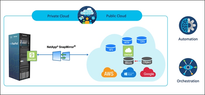
There are multiple advantages of this solution, such as:
● Orchestration and Automation
Cisco Intersight simplifies the day-to-day operations of the industry trusted FlexPod hybrid cloud infrastructure by providing consistent orchestration frameworks that are delivered via automation.
● Customized Protection
Cloud Volumes ONTAP provides block-level data replication from ONTAP to the cloud that keeps the destination up to data through incremental updates. Users can specify a synchronization schedule such as every minute or every hour, based on which any changes at the source will be transferred over.
● Seamless Failover and Failback
When a disaster occurs, storage administrators can quickly set the failover to the cloud volumes. When the primary site is recovered, the new data created in the DR environment is synchronized back to the source volumes enabling the secondary data replication to be re-established.
● Efficiency
The storage space and costs for the secondary cloud copy are optimized through the usage of data compression, thin provisioning, and deduplication. The data is transferred on the block-level in their compressed and deduplicated form, improving the speed of the transfers. Data is also automatically tiered to low-cost object storage and only brought back to high-performance storage when accesses, such as in a DR scenario. This significantly reduces ongoing storage costs.
● Increase IT Productivity
Using Intersight as the single enterprise-grade, secure platform for infrastructure and application lifecycle management, simplify configuration management and automate of manual tasks at scale for the solution.
This section describes the components used in the solution outlined in this study.
FlexPod is a defined set of hardware and software that serves as an integrated foundation for both virtualized and non-virtualized solutions. VMware vSphere® built on FlexPod includes NetApp AFF storage, Cisco Nexus® networking, Cisco MDS storage networking, the Cisco Unified Computing System (Cisco UCS®), and VMware vSphere software in a single package. The design is flexible enough that the networking, computing, and storage can fit in one data center rack or be deployed according to a customer's data center design. Port density enables the networking components to accommodate multiple configurations of this kind.
One benefit of the FlexPod architecture is the ability to customize or "flex" the environment to suit a customer's requirements. A FlexPod can easily be scaled as requirements and demand change. The unit can be scaled both up (adding resources to a FlexPod unit) and out (adding more FlexPod units). The reference architecture detailed in this document highlights the resiliency, cost benefit, and ease of deployment of a Fibre Channel and IP-based storage solution. A storage system capable of serving multiple protocols across a single interface allows for customer choice and investment protection because it truly is a wire-once architecture.
FlexPod Components
FlexPod architecture includes the following core components:
● Cisco UCS
● Cisco Nexus® Family switches
● Cisco MDS Family switches
● NetApp AFF/FAS storage systems
Figure 2. FlexPod Component Families
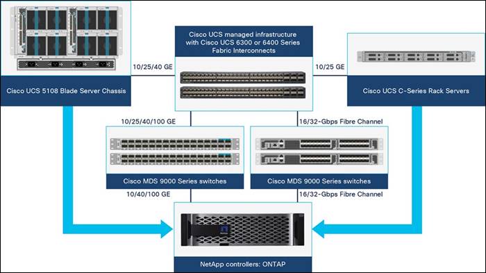
These components are connected and configured according to the best practices of both Cisco and NetApp to provide an ideal platform for running a variety of enterprise workloads with confidence. FlexPod can scale up for greater performance and capacity (adding compute, network, or storage resources individually as needed), or it can scale out for environments that require multiple consistent deployments (such as rolling out of additional FlexPod stacks). The reference architecture covered in this document leverages Cisco Nexus 9000 for the network switching element and pulls in the Cisco MDS 9000 for the SAN switching component.
One of the key benefits of FlexPod is its ability to maintain consistency during scale. Each of the component families shown (Cisco UCS, Cisco Nexus, and NetApp AFF) offers platform and resource options to scale the infrastructure up or down, while supporting the same features and functionality that are required under the configuration and connectivity best practices of FlexPod.
Why FlexPod?
The following are some of the benefits of FlexPod:
● Consistent Performance and Scalability
◦ Consistent sub-millisecond latency with 100% flash storage
◦ Consolidate 100’s of enterprise-class applications in a single rack
◦ Scales easily, without disruption
◦ Continuous growth through multiple FlexPod CI deployments
● Operational Simplicity
◦ Fully tested, validated, and documented for rapid deployment
◦ Reduced management complexity
◦ Auto-aligned 512B architecture removes storage alignment issues
◦ No storage tuning or tiers necessary
● Lowest TCO
◦ Dramatic savings in power, cooling, and space with 100 percent Flash
◦ Industry leading data reduction
● Enterprise-Grade Resiliency
◦ Highly available architecture with no single point of failure
◦ Nondisruptive operations with no downtime
◦ Upgrade and expand without downtime or performance loss
◦ Native data protection: snapshots and replication
◦ Suitable for even large resource-intensive workloads such as real-time analytics or heavy transactional databases
Cisco Intersight is a SaaS platform which delivers intelligent automation, observability and optimization for traditional and cloud-native applications and infrastructure. The platform helps drive change with IT teams and delivers an operating model designed for hybrid cloud.
Cisco Intersight provides the following:
● Faster Delivery
Delivered “as a Service”, from the cloud or in the customers data center, with frequent updates and continued innovation, due to an agile-based software development model. This way, customer can just focus on accelerating delivery for line-of-business.
● Simplified operations
Simplify operations by using a single secure SaaS-delivered tool, with common inventory, authentication and APIs to work across full stack and all locations, eliminating silos across teams. From managing physical servers and hypervisors on-prem, to VMs, K8s, serverless, automation, optimization, and cost control across both on-prem and public clouds.
● Continuous optimization
Continuously optimize environment using intelligence provided by Intersight across every layer, as well as Cisco TAC. That intelligence is converted into recommended and automatable actions so you can adapt real-time to every change: from moving workloads and monitoring health of physical servers, to auto sizing K8s clusters, to cost reduction recommendations the public clouds you work with.
Cisco Intersight Management
There are two modes of management operations possible with Cisco Intersight. UCSM Managed Mode (UMM) and Intersight Managed Mode (IMM). You can select the native UCSM Managed Mode (UMM) or Intersight Managed Mode (IMM) for the Fabric attached Cisco UCS Systems during initial setup of the Fabric Interconnects.
UCSM Managed Mode allow to connect existing Cisco UCS infrastructure managed with Cisco UCS Manager (UCSM) to Cisco Intersight. In addition, Intersight integrates with third-party storage, cloud services, virtualization, and container platforms.
Intersight Managed Mode (IMM) is a new architecture that manages the Cisco UCS Fabric Interconnected systems through a Redfish-based standard model. Intersight Managed Mode unifies the capabilities of the Cisco UCS Systems and the cloud-based flexibility of Intersight, thus unifying the management experience for the standalone and Fabric Interconnect attached systems. Intersight Management Model standardizes policy and operation management for UCS-FI-6454, UCS-FI-64108, and Cisco UCS M5, M6, and X-Series servers.
Cisco Intersight Managed Mode (IMM) transition tool helps bootstrap new IMM deployments by replicating the configuration attributes of the existing Cisco UCS Mana infrastructure and by converting the existing Service Profile Templates to IMM Server Profile Templates to accelerate deployment of new servers in IMM. Download image and user guides are available at: https://ucstools.cloudapps.cisco.com/
Cisco Intersight Connected Virtual Appliance and Private Virtual Appliance
In addition to the SaaS deployment model running on Intersight.com, on-premises options can be purchased separately. The Cisco Intersight Connected Virtual Appliance and Cisco Intersight Private Virtual Appliance are available for organizations that have additional data locality or security requirements for managing systems. The Cisco Intersight Connected Virtual Appliance delivers the management features of the Cisco Intersight platform in an easy-to-deploy VMware Open Virtualization Appliance (OVA) or Microsoft Hyper-V Server virtual machine that allows you to control the system details that leave your premises. The Cisco Intersight Private Virtual Appliance is provided in a form factor specifically designed for users who operate in disconnected (air gap) environments. The Private Virtual Appliance requires no connection to public networks or back to Cisco to operate. At this time, Cisco Intersight managed mode configuration is available only through the Cisco Intersight SaaS platform and Connected Virtual Appliance.
Cisco Intersight Cloud Orchestrator
Cisco Intersight Cloud Orchestrator is a powerful automation tool that enables IT operations teams not just to move at the speed of the business and standardize while reducing risk across all domains but also to provide a consistent cloud-like experience for users.
Cisco Intersight Cloud Orchestrator simplifies orchestration and automation for infrastructure and workloads across hybrid cloud by providing an easy-to-use workflow designer. Based on a library of curated, multi-domain tasks (custom or provided by Cisco), it enables users to create workflows, quickly and easily, without being coding experts! This enables quick and easy automation and deployment of any infrastructure resource, from servers, to VMs and the network, taking away some of the complexity of operating your hybrid IT environment.
The ICO workflow designer provides:
● Low/no-code workflow creation with a modern, drag-and-drop user experience with control flow support. The workflow designer includes policy-based, built-in tasks for Cisco UCS, virtualization, and other Cisco devices. A Software Development Kit (SDK) enables Cisco technology partners to build their own ICO tasks to develop custom solutions.
● Rollback capabilities to selectively undo a workflow’s tasks in the event of failure, or to deprovision infrastructure, which when done manually can often take longer and be more error prone than straight provisioning.
● Extensibility with a task designer that expands the functionality of currently supported targets or can be used to create new ones. ICO currently supports Web API with more integration options to come.
With Cisco Intersight Cloud Orchestrator you can truly evolve your automation strategy to provide consistent experience across on-premises resources and public clouds.
The following are some key benefits:
● Bring your public cloud and on-premises resources together with a solution that extends orchestration across any infrastructure and workload and integrates with the tools of your choice
● Save time and streamline automation with a user-friendly GUI-based designer that makes it easy to create and execute complex workflows without being a coding expert
● Standardize your deployment process with self-service delivery and boost productivity with a selection of validated blueprints
● Reduce risks by enforcing policy using rules for what can be orchestrated and who can access workflows and tasks
Cisco Intersight Service for HashiCorp Terraform
Infrastructure as Code (IaC) is the method of defining and provisioning infrastructure using definition files containing code. IaC adoption in public clouds allow application agility in the following ways:
● Address the problem of environment drift in the release pipeline IaC manages infrastructure using source code version in Git as the single source of truth.
● CICD toolchains automatically test, deploy, and track pull requests and configuration changes to your infrastructure.
● Regardless of an environment’s starting state, deployments always use the same configuration.
● Enables users to transition from mutable workloads (take existing infrastructure and try and upgrade in place) to immutable workloads (take existing infrastructure, create new infrastructure, and destroy the existing device).
Infrastructure as Code (IaC) enables IT and development teams to automate and scale the provisioning and management of IT resources aligned with application source-code releases in a descriptive manner. HashiCorp Terraform is the industry-leading IaC platform. Cisco Intersight Service for HashiCorp Terraform (IST) addresses the challenge of securely connecting and configuring on-premises environments to work with Terraform Cloud Business. Rather than spending time on firewall configurations or manually deploying and maintaining local runtime environments for Terraform Cloud Agents, IST removes the discomfort of DIY approaches by making the integration quick and easy.
Leveraging Intersight Assist users can integrate Terraform Cloud Business with Cisco Intersight, enabling secure communication between on-premises data centers and edge locations with the IaC platform. This means users can spend less time managing the end-to-end lifecycle of Terraform Cloud Agents, benefiting from native integration directly within Intersight, including upgrades and the ability to scale as demand grows. In addition, with common Single Sign-On (SSO), users can cross launch directly from Intersight into Terraform Cloud.
With Intersight Service for HashiCorp Terraform, seamlessly and securely extend modern, public cloud automation tools and best-practices to any on-premises environments, delivering consistent agility and flexibility for your DevOps teams while reducing operational overhead for ITOps.
Key benefits include:
● Reduce operational complexity and increase productivity using Infrastructure as Code to provision and manage your hybrid cloud environment
● Give your DevOps teams what they need with a ready-to-be-consumed on-premises infrastructure, securely integrated with their IaC tools
● Reduce risk with enterprise-grade capabilities to manage infrastructure in private environments, such as Single Sign-on (SSO) and audit logging
● Automate across all your hybrid cloud resources without having to manage more tools to integrate with Terraform Cloud Business
● Benefit from a hybrid cloud partnership between industry-leaders with a rich catalog of Terraform providers and a single point of contact for support and enablement
● Simplify usability with quality-of-life features such as common APIs and cross-launching through Cisco Intersight.
NetApp Cloud Volumes ONTAP is a software-defined storage offering that delivers advanced data management for file and block workloads. With Cloud Volumes ONTAP, you can optimize your cloud storage costs and increase application performance while enhancing data protection, security, and compliance.
Key benefits include:
● Leverage built-in data deduplication, data compression, thin provisioning, and cloning to minimize storage costs.
● Ensure enterprise reliability and continuous operations in case of failures in your cloud environment.
● Cloud Volumes ONTAP leverages SnapMirror, NetApp’s industry-leading replication technology, to replicate on-premises data to the cloud so it’s easy to have secondary copies available for multiple use cases.
● Cloud Volumes ONTAP also integrates with Cloud Backup service to deliver backup and restore capabilities for protection, and long-term archive of your cloud data.
● Switch between high and low-performance storage pools on-demand without taking applications offline.
● Ensure consistency of NetApp Snapshot copies using NetApp SnapCenter.
● Cloud Volumes ONTAP supports data encryption and provides protection against viruses and ransomware.
● Integration with Cloud Data Sense helps you understand data context and identify sensitive data.
Cloud Central provides a centralized location to access and manage NetApp cloud data services. These services enable you to run critical applications in the cloud, create automated DR sites, back up your SaaS data, and effectively migrate and control data across multiple clouds. For more information, refer to Cloud Central.
Cloud Manager is an enterprise-class, SaaS-based management platform that enables IT experts and cloud architects to centrally manage their hybrid multi-cloud infrastructure using NetApp’s cloud solutions. It provides a centralized system for viewing and managing your on-premises and cloud storage, supporting hybrid, multiple cloud providers and accounts. To find more info, refer to Cloud Manager.
Connector is an instance which enables Cloud Manager to manage resources and process within public cloud environment. A Connector is required to use many features which Cloud manager provides. A Connector can be deployed in the cloud or on-premises network.
Connector is supported in the following locations:
● Amazon Web Services
● Microsoft Azure
● Google Cloud
● On your premises
When you create your first Cloud Volumes ONTAP working environment, Cloud Manager will prompt you to create a Connector if you don’t have one yet. The user who creates a Connector from Cloud Manager needs specific permissions to deploy the instance in your cloud provider of choice. Cloud Manager will remind you of the permissions requirements when you create a Connector.
The Connector needs specific cloud provider permissions to perform operations on your behalf. For example, to deploy and manage Cloud Volumes ONTAP. When you create a Connector directly from Cloud Manager, Cloud Manager creates the Connector with the permissions that it needs. To learn more about Connectors, refer to Connectors.
It is essential for businesses to have a feasible, robust, and sustainable Business Continuity and Disaster Recovery (BCDR) plan in case of an outage. While there are several options that businesses can evaluate and explore, it all comes down to the cost of implementation, the Recovery Point Objective and the Recovery Time Objective that the plan can deliver.
For most businesses, the fundamental requirement in a BCDR plan is to have a failover site to sustain their operations while they take the necessary steps to recover the primary production environment. In such situations, the public cloud can serve as a DR environment which provides the required fault tolerance, on-demand resource provisioning and elasticity leading to a consumption-based billing that helps in lowering the overall cost of the BCDR implementation.
The implementation of the BCDR plan in a public cloud is not a straightforward approach especially when dealing with a high volume of mission critical data. The need for a secure, scalable, reliable, cost-optimized, and unified data management service that integrates seamlessly with the on-premises environment is an absolute requirement.
NetApp Cloud Volumes ONTAP when clubbed with an on-premises FlexPod running ONTAP, provides a secure data pathway for the mission critical data to be replicated to the cloud at a desired cadence driven by the RPO objectives and when there is a need to flip operations to the cloud in case of a disaster the replicated data in the cloud can be promoted to production at the click of a button. The entire data replication relationship between FlexPod and the Cloud Volumes ONTAP instance in the public cloud can be managed from the single control plane of Cisco Intersight.
The audience for this document includes, but is not limited to; sales engineers, field consultants, professional services, IT managers, partner engineers, Site Reliability Engineers, Cloud Architects, Cloud Engineers and customers who want to take advantage of an infrastructure built to deliver IT efficiency and enable IT innovation.
Requirements and Specification
Cisco Intersight uses a subscription-based license with multiple tiers. Each Cisco endpoint (Cisco UCS server, Cisco HyperFlex system, or Cisco UCS Director software) automatically includes a Cisco Intersight Base when you access the Cisco Intersight portal and claim a device.
Cisco Intersight license tiers
The following are the Cisco Intersight license tiers:
● Cisco Intersight Essentials—Essentials includes ALL functionality of Base with the additional features including Cisco UCS Central and Cisco IMC Supervisor entitlement, policy-based configuration with Server Profiles, firmware management, and evaluation of compatibility with the Hardware Compatibility List (HCL).
● Cisco Intersight Advantage—Advantage offers all features and functionality of the Base and Essentials tiers.
● Cisco Intersight Premier—In addition to the functionality provided in the Advantage tier, Intersight Premier includes full subscription entitlement for Cisco UCS Director at no additional cost.
More information about Intersight Licensing and features supported in each licensing can be found at: https://intersight.com/help/saas/getting_started/licensing_requirements#intersight_licensing
View current Cisco Intersight Infrastructure Service licensing.
Note: In our solution, we will use Intersight Cloud Orchestrator and Intersight Service for HashiCorp Terraform. These features are available for users with the Intersight Premier license so this licensing tier must be enabled.
Procedure 1. Activate a Cisco Intersight License
Follow these steps to register your license in Cisco Intersight:
Step 1. Log into Intersight with Account Administrator privileges.
Step 2. From Settings icon > Settings > License, click Register.
Step 3. In the Set Token page, enter the Product Instance Registration Token. Click Cisco Smart Software Manager to obtain your Intersight Registration token. If you do not have a Smart Account, create one from link: https://software.cisco.com/#SmartLicensing-Alerts. You can purchase the subscription and select the required Cisco UCS Server volume tier for the selected subscription duration from the same Smart Account. Click Next.
Step 4. In the Set Product page, select the required default license tier for Intersight and/or Workload Optimizer. Enabling Move all Servers To Default Tier, tags and moves all the existing servers to the default tier.
The available license tiers are:
● Intersight—Choose Essentials, Advantage, or Premier. For more information on the Intersight licensing tiers, see the Intersight Licensing section.
● Workload Optimizer—Toggle ON Activate Workload Optimizer and click Essentials, Advantage, or Premier. For more information on the Workload Optimizer licensing tiers, see the Workload Optimizer Licensing section.
License Status
The Cisco Intersight account license state could be one of the following depending on your subscription status:
● Not Used—This status is displayed when the server count in a license tier is 0.
● In Compliance—The account licensing state is in compliance and all the supported features are available to the users.
● Out of Compliance—The account license status displays Out of Compliance in the following cases:
◦ When not enough valid licenses are available because the subscription has reached the end of term, or you have more servers in the license tier than available licenses.
◦ When the grace period of 90 days is active or expired
◦ The servers are added to the account but not registered in the Smart Licensing account
When an account license status moves to Out of Compliance, a grace period of 90 days is triggered. In this period, you can continue to use the premium features, but the account license status remains Out of Compliance. To get back in compliance, you must purchase additional licenses or remove a server from the existing tier or move it to a lower tier. If you do not renew your license within the 90 days, the license state moves to Grace Expired and the license is downgraded to Base-level functionality and the premium features become unavailable. You must register a valid license again to resume using the features.
For example, if an account has a valid license for 20 servers and if you claim another server into the account, the status moves to Out of Compliance and the grace period is initiated. However, you can continue to access the features as before. To restore the In Compliance status, you can move one of the servers to a lower tier (Base/ Essentials/Advantage, as required) from the Actions Menu in the Server Details page, or from the Server /Bulk Actions in the Table view.
Note: After you purchase and activate additional licenses from the Cisco Smart Licensing portal, click the Refresh icon in the Subscription pane to sync the licensing status with that in the portal.
A few licensing options are available for Cloud Volumes ONTAP. Each of these licensing options enables you to select a configuration that meets your needs.
Table 1 lists the licensing options for Cloud Volumes ONTAP.
| Charging method |
Highlights |
Support |
Max system capacity |
| Capacity-based license: Essentials package |
Pay per TiB of capacity for one or more Cloud Volumes ONTAP systems Provides a la carte licensing for Cloud Volumes ONTAP Available by bringing your own license (BYOL) purchased from NetApp |
Included |
2 PiB |
| Capacity-based license: Professional package |
Pay per TiB of capacity for one or more Cloud Volumes ONTAP systems Provides licensing for any Cloud Volumes ONTAP configuration Includes volume backups using Cloud Backup (for volumes charged against this license) Available through an AWS Marketplace annual contract or by purchasing a license from NetApp (BYOL) |
Included |
2 PiB |
| Keystone Flex Subscription |
Pay-as-you-grow by TiB through a NetApp subscription Charging is based on the size of committed capacity The committed capacity is shared between the Cloud Volumes ONTAP systems deployed with the subscription Available for HA pairs only |
Included |
2 PiB |
| PAYGO by node |
Pay-as-you-go by the hour through a marketplace subscription from your cloud provider Charging is per Cloud Volumes ONTAP node Available in three licensing options: Explore, Standard, and Premium |
Included, but you must activate support. |
Explore: 2 TiB Standard: 10 TiB Premium: 368 TiB |
| Node-based license |
The previous generation BYOL for Cloud Volumes ONTAP A node-based license is available for license renewals only |
Included |
368 TiB per license |
Freemium offering
A new offering from NetApp that provides all Cloud Volumes ONTAP features free of charge from NetApp (cloud provider charges still apply):
● No license or contract is needed.
● Support is not included.
● You’re limited to 500 GiB of provisioned capacity per Cloud Volumes ONTAP system.
● You can use up to 10 Cloud Volumes ONTAP systems with the Freemium offering per NetApp account.
● If the provisioned capacity for a Cloud Volumes ONTAP system exceeds 500 GiB, Cloud Manager converts the system to the Essentials package (which is a capacity-based license) and charging starts.
Any other systems that have less than 500 GiB of provisioned capacity stay on the Freemium offering (if they were deployed using the Freemium offering).
To know more about how to obtain and apply license, refer to licensing overview.
Hardware and Software Revisions
This hybrid cloud solution can be extended to any FlexPod Datacenter environment that is running supported versions of software, firmware and hardware as defined in the NetApp Interoperability Matrix Tool and Cisco UCS Hardware Compatibility List.
The FlexPod solution used as the baseline platform in the on-premises environment has been deployed as per the guidelines and specifications described in the FlexPod Datacenter with Cisco UCS 4.2(1) in UCS Managed Mode, VMware vSphere 7.0 U2, and NetApp ONTAP 9.9 Design Guide.
Note: The workload running in the FlexPod Datacenter can be virtualized, non-virtualized and containerized applications.
Click the following links for more information:
● NetApp Interoperability Matrix Tool
● Cisco UCS Hardware and Software Interoperability Tool
Table 2. FlexPod Hardware and Software Revisions
| Component |
Product |
Version |
| Compute |
Cisco UCS B200 M5 Blades |
4.2(1f) |
| Cisco UCS B200 M6 Servers |
4.2(1f) |
|
| Cisco UCS X210C |
5.0(1b) |
|
| Cisco UCS Fabric Interconnects 6454 |
4.2(1f) |
|
| Network |
Cisco Nexus 93180YC-FX NX-OS |
9.3(8) |
| Cisco MDS 9132T |
8.4(2c) |
|
| Storage |
NetApp AFF A400 |
9.9.1P2 |
| NetApp ONTAP Tools for VMware |
9.8 |
|
| NetApp NFS Plugin for VMware VAAI |
2.0-15 |
|
| NetApp Active IQ Unified Manage |
9.9P1 |
|
| NetApp SnapCenter Plugin for VMware |
4.5 |
|
| Software |
VMware ESXi nenic Ethernet Driver |
1.0.35.0 |
| VMware ESXi nfnic FC Driver |
5.0.0.12 |
|
| vSphere ESXi |
7.0(U2) |
|
| VMware vCenter Appliance |
7.0 U2b |
|
| Cisco Intersight Assist Virtual Appliance |
1.0.9-342 |
The execution of Terraform configurations happens on the Terraform Cloud for Business account. Terraform configuration uses the Terraform provider for NetApp Cloud Manager.
Table 3. Vendors, products, and versions
| Vendor |
Product |
Version |
| NetApp |
netapp-cloudmanager |
21.12.0 |
| HashiCorp |
Terraform |
1.0.0 |
Table 4. Cloud Manager and Cloud Volumes ONTAP versions
| Vendor |
Product |
Version |
| NetApp |
Cloud Volumes ONTAP |
9.10.1RC1 |
| Cloud Manager |
3.9.13 Build:1 |
|
| Mediator |
9-10-1rc1-mediator |
This section describes the design and architecture of the solution.
Solution Architecture
Figure 3 illustrates the architecture of this solution.
Figure 3. Solution architecture
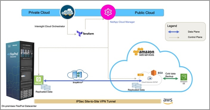
Figure 3 represents the solution architecture comprised of the FlexPod Datacenter on-premises environment, NetApp Cloud Volumes ONTAP (CVO) running on Amazon Web Services, and the Cisco Intersight and NetApp Cloud Manager SaaS control planes.
The control planes and data planes are clearly indicated between the endpoints. The Data Plane runs between the ONTAP instance running on All Flash FAS in the FlexPod and the NetApp CVO instance in AWS by leveraging a secure site-to-site VPN connection.
The replication of the workload data from FlexPod Datacenter to NetApp CVO is handled by NetApp SnapMirror and the overall process is orchestrated using Cisco Intersight Cloud Orchestrator for both the on-premises and cloud environments.
Cisco Intersight Cloud Orchestrator consumes the Terraform Resource Providers for NetApp Cloud Manager to carry out the operations related to NetApp CVO Deployment and establishing the data replication relationships.
An optional backup and tiering of the cold data residing in the NetApp CVO instance to AWS S3 is also supported with this solution.
This section details the requirements for the hybrid cloud networking elements that form a core part of this solution.
You can create dedicated VPC in any region to deploy Connector and CVO. View the full list of supported regions. Also define the subnet per availability zone, route table and internet gateway.
A VPC endpoint is required to establish the connectivity between the VPC, and AWS supported services without requiring internet gateway, NAT device, VPN connection or direct connect. The VPC is not exposed to public internet and the communication will happen over AWS private network. There are three types of VPC endpoints: Interface endpoints, Gateway Load Balancer endpoints, and Gateway endpoints.
AWS VPN is used in the solution to establish secure connection between on-prem FlexPod network and the AWS global network. AWS Site-to-Site VPN creates encrypted tunnels between your network and your Amazon Virtual Private Clouds or AWS Transit Gateways.
The VPN connectivity utilizes the public internet, which can have unpredictable performance and can possess some security concerns. AWS direct connect bypass the public internet and establishes a secure dedicated connection from op-prem to AWS. AWS direct connect is a great option for customers that are seeking secure, low latency connectivity into AWS. If the customer already has AWS direct connect then the same connection can be used to establish communication between on-prem FlexPod and CVO instance.
Cloud Volumes ONTAP for Disaster Recovery
NetApp CVO can be deployed in various deployment modes; this section covers in detail all the modes of deployment and their associated pre-requisites. You can select any of the modes of deployment that match your business specific requirements.
CVO Deployment Modes and Architecture
Cloud Volumes ONTAP is available in AWS as a single node system and as a high-availability (HA) pair of nodes. Based on the requirement, you can select CVO deployment modes. Upgrading a single node system to an HA pair is not supported. If you want to switch between a single node system and an HA pair, then you need to deploy a new system and replicate data from the existing system to the new system.
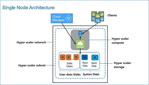
Cloud Volumes ONTAP Single Node
Cloud Volumes ONTAP deployment mode in AWS as a single node system that is ideal for disaster recovery, backups, and workloads that do not require high availability. In this mode all the LIFs will be assigned IP from same subnet.
Figure 4. CVO single node architecture
High Availability Pair Node
A Cloud Volumes ONTAP high availability (HA) configuration provides nondisruptive operations and fault tolerance. In AWS, data is synchronously mirrored between the two nodes.
In AWS, Cloud Volumes ONTAP HA configurations include the following components:
● Two Cloud Volumes ONTAP nodes whose data is synchronously mirrored between each other.
● A mediator instance that provides a communication channel between the nodes to assist in storage takeover and giveback processes.
Cloud Volumes ONTAP HA Single Availability Zone
Cloud Volumes ONTAP deployment mode in AWS as a single AZ HA pair that is ideal for fault tolerance and nondisruptive operations as it protects against failures within a single AZ. This HA configuration ensures high availability of your data if an instance that runs a Cloud Volumes ONTAP node fails. All data is natively accessible from outside of the VPC.
In this mode there will be two nodes and a mediator instance that will be deployed in single AZ. Because this configuration is in a single AZ it does not require floating IP address and you can use same set of IP addresses for NFS and CIFS data access from within the VPC and from outside the VPC. These IP addresses automatically migrate between HA nodes if failures occur.
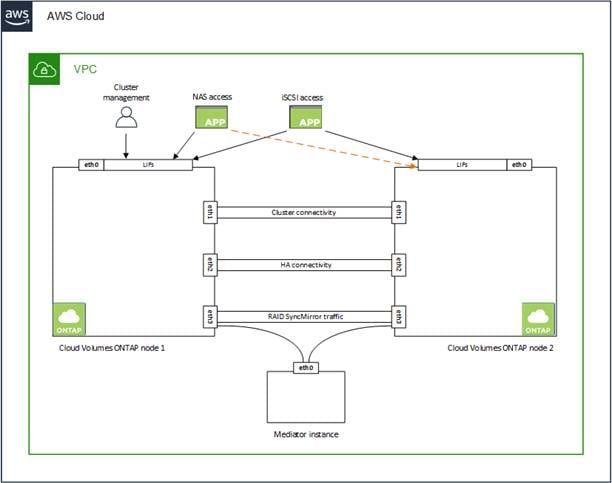
Figure 5. CVO HA Architecture
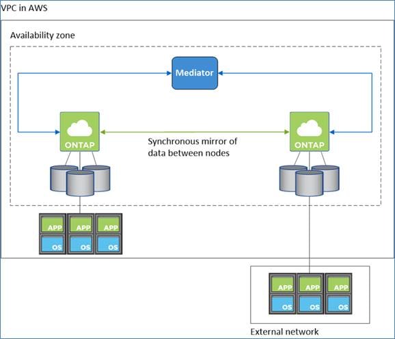
Unlike an ONTAP cluster, storage in a Cloud Volumes ONTAP HA pair is not shared between nodes. Instead, data is synchronously mirrored between the nodes so that the data is available in the event of failure. You can use an HA pair as an active-active configuration, in which both nodes serve data to clients, or as an active-passive configuration, in which the passive node responds to data requests only if it has taken over storage for the active node:
● For iSCSI, Cloud Volumes ONTAP uses multipath I/O (MPIO) and Asymmetric Logical Unit Access (ALUA) to manage path failover between the active-optimized and non-optimized paths.
● For NAS configurations, the data IP addresses can migrate between HA nodes if failures occur. This ensures client access to storage.
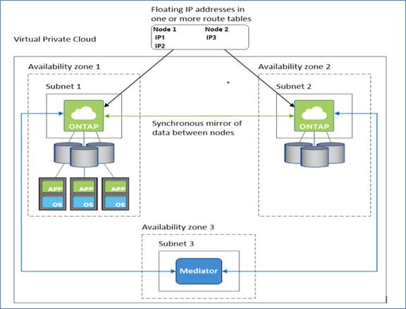
Cloud Volumes ONTAP HA Multi Availability Zones
Cloud Volumes ONTAP deployment mode in AWS as a HA pair multi-AZ that is ideal for fault tolerance and nondisruptive operations for business continuity as it provides maximum protection against AZ failures. This HA configuration ensures high availability of your data if a failure occurs with an Availability Zones or an instance that runs a Cloud Volumes ONTAP node. Both Cloud Volumes ONTAP nodes must be deployed in different Availability Zones. A third Availability Zone is recommended for the HA mediator.
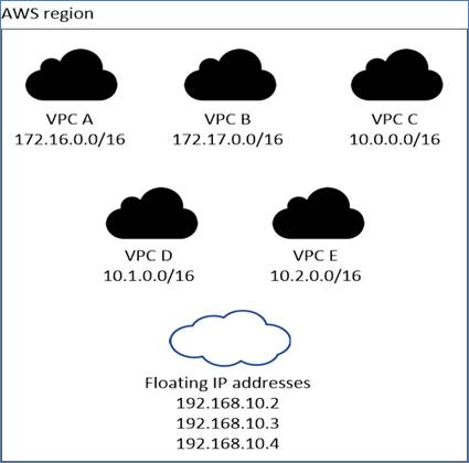
When an HA configuration is spread across multiple Availability Zones, floating IP addresses enable NAS client access. The floating IP addresses, which must be outside of the CIDR blocks for all VPCs in the region, can migrate between nodes when failures occur. They aren’t natively accessible to clients that are outside of the VPC, unless an AWS transit gateway is set up.
If there is no transit gateway, private IP addresses are available for NAS clients that are outside the VPC. However, these IP addresses are static—they can’t failover between nodes. The floating IP needs to be specified during the CVO deployment. The private IP addresses are automatically created by Cloud Manager.
Figure 6. CVO HA Multi-AZ architecture
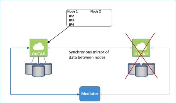
Takeover and giveback:
● For iSCSI, Cloud Volumes ONTAP uses multipath I/O (MPIO) and Asymmetric Logical Unit Access (ALUA) to manage path failover between the active-optimized and non-optimized paths.
● For NAS, the takeover occurs using floating IP. The node’s floating IP address that clients use to access data moves to the other node.
Figure 7. Takeover and Giveback
Networking Requirements for Cloud Volumes ONTAP in AWS
Cloud Manager handles the setup of networking components for Cloud Volumes ONTAP, such as IP addresses, netmasks, and routes and so on.
The following sections describe the requirements that must be met in AWS.
Outbound internet access for Cloud Volumes ONTAP nodes
Cloud Volumes ONTAP nodes require outbound internet access to send messages to NetApp AutoSupport, which proactively monitors the health of your storage. By default, AutoSupport is enabled on each node to send messages to technical support using the HTTPS transport protocol.
Note: If you have a NAT instance, you must define an inbound security group rule that allows HTTPS traffic from the private subnet to the internet.
Outbound internet access for the HA mediator
The HA mediator instance must have an outbound connection to the AWS EC2 service so it can assist with storage failover. To provide the connection, you can add a public IP address, specify a proxy server, or use a manual option.
The manual option can be a NAT gateway or an interface VPC endpoint from the target subnet to the AWS EC2 service. For details about VPC endpoints, refer to AWS Documentation: Interface VPC Endpoints (AWS PrivateLink).
Security groups
Cloud Manager creates a security group but if you want to use your own then refer to Security group rules.
To replicate data between a Cloud Volumes ONTAP system in AWS and ONTAP systems in other networks, you must have a VPN connection between the AWS VPC and the other network.
Cloud Manager automatically allocates the required number of private IP addresses to Cloud Volumes ONTAP. You need to ensure that your networking has enough private IP addresses available.
The number of LIFs that Cloud Manager allocates for Cloud Volumes ONTAP depends on whether you deploy a single node system or an HA pair. A LIF is an IP address associated with a physical port.
IP addresses for a single node system
Table 5 lists the Cloud Manager IP addresses to a single node system.
Table 5. Cloud Manager IP addresses
| LIF name |
Assigned Interface |
Purpose |
| Cluster management LIF |
eth0 |
Administrative management of cluster |
| Node management LIF |
eth0 |
Administrative management of a node |
| Intercluster LIF |
eth0 |
Replication |
| NAS data LIF |
eth0 |
Client access over NAS protocol |
| iSCSI data LIF |
eth0 |
Client access over iSCSI protocol |
| SVM management LIF |
eth0 |
SVM management |
IP addresses for a HA pairs
HA pairs require more IP addresses than a single node system does. These IP addresses are spread across different ethernet interfaces, as shown in Figure 8.
Figure 8. CVO HA LIFs and Interfaces overview
Note: An HA pair deployed in a single AWS Availability Zone (AZ) requires 15 private IP addresses.
Table 6 lists the details about LIFs that are associated with each private IP address.
Table 6. LIFs for HA pairs in a single AZ
| LIF name |
Assigned Interface |
Node |
Purpose |
| Cluster management |
eth0 |
node 1 |
Administrative management of the entire cluster (HA pair) |
| Node management |
eth0 |
node 1 and node 2 |
Administrative management of a node |
| Intercluster |
eth0 |
node 1 and node 2 |
Cross-cluster communication, backup, and replication |
| NAS data |
eth0 |
node1 |
Client access over NAS protocol |
| iSCSI data |
eth0 |
node 1 and node 2 |
Client access over the iSCSI protocol |
| Cluster connectivity |
eth1 |
node 1 and node 2 |
Enables the nodes to communicate with each other and to move data within the cluster |
| HA connectivity |
eth2 |
node 1 and node 2 |
Communication between the two nodes in case of failover |
| RSM iSCSI traffic |
eth3 |
node 1 and node 2 |
RAID SyncMirror iSCSI traffic, as well as communication between the two Cloud Volumes ONTAP nodes and the mediator |
| Mediator |
eth0 |
Mediator |
A communication channel between the nodes and the mediator to assist in storage takeover and giveback processes |
Note: An HA pair deployed in a multiple AWS Availability Zone (AZ) requires 13 private IP addresses.
Table 7 lists the details about LIFs that are associated with each private IP address.
Table 7. LIFs for HA pairs in a multiple AZs
| LIF name |
Assigned Interface |
Node |
Purpose |
| Node management |
eth0 |
node 1 and node 2 |
Administrative management of a node |
| Intercluster |
eth0 |
node 1 and node 2 |
Cross-cluster communication, backup, and replication |
| iSCSI data |
eth0 |
node 1 and node 2 |
Client access over the iSCSI protocol. This LIF also manages the migration of floating IP addresses between nodes |
| Cluster connectivity |
eth1 |
node 1 and node 2 |
Enables the nodes to communicate with each other and to move data within the cluster |
| HA connectivity |
eth2 |
node 1 and node 2 |
Communication between the two nodes in case of failover |
| RSM iSCSI traffic |
eth3 |
node 1 and node 2 |
RAID SyncMirror iSCSI traffic, as well as communication between the two Cloud Volumes ONTAP nodes and the mediator |
| Mediator |
eth0 |
Mediator |
A communication channel between the nodes and the mediator to assist in storage takeover and giveback processes |
Requirements for HA pairs in multiple Availability Zones
Additional AWS networking requirements apply to Cloud Volumes ONTAP HA configurations that use multiple Availability Zones (Azs). This HA deployment model uses multiple Availability Zones to ensure high availability of the data. It’s recommended to use a dedicated AZ for each Cloud Volumes ONTAP instance and the mediator instance, which provides a communication channel between the HA pair. A subnet should be available in each Availability Zone.
HA configurations in multiple Azs use floating IP addresses that migrate between nodes if failures occur. They are not natively accessible from outside the VPC. To make floating IP accessible a Transit Gateway is required. You need to enter the floating IP addresses in Cloud Manager when you create a Cloud Volumes ONTAP HA working environment. Cloud Manager allocates the IP addresses to the HA pair when it launches the system.
The floating IP addresses must be outside of the CIDR blocks for all VPCs in the AWS region in which you deploy the HA configuration.
The floating IP addresses is a logical subnet that’s outside of the VPCs in your region. Cloud Manager will automatically add the static route to the route table of the VPC which will be selected during Cloud Volumes ONTAP deployment.
Figure 9. CVO HA Multi-AZ Floating IP Overview
Connect to NetApp management tools
To use NetApp management tools with HA configurations that are in multiple Azs, there are two connection options:
● Deploy the NetApp management tools in a different VPC and set up an AWS transit gateway. The gateway enables access to the floating IP address for the cluster management interface from outside the VPC.
● Deploy the NetApp management tools in the same VPC with a similar routing configuration as NAS clients.
Cloud Volumes ONTAP Deployment Specifications
Supported Regions
Cloud Volumes ONTAP is supported in most AWS regions. Newer AWS regions must be enabled before you can create and manage resources in those regions. Learn how to enable a region.
Compute Instances for running CVO
Cloud Volumes ONTAP supports several instance types, depending on the license type that you select. Supported configurations for Cloud Volumes ONTAP in AWS
Sizing
Sizing your Cloud Volumes ONTAP system can help you meet requirements for performance and capacity. Cloud Volumes ONTAP sizer is a tool that will help you to size your CVO environment to decide the best architecture and resources to leverage for your specific needs.
TCO Calculator
Easily calculate your storage costs on AWS, Azure or Google Cloud with Cloud Volumes ONTAP using this free, simplified, and easy to navigate calculator. Learn more about the TCO calculator.
This section describes the details of deployment. At a high level, deploying a disaster recovery solution across hybrid cloud consists of the steps shown below. The details of these steps are presented in the following sections.
1. Deploy FlexPod Datacenter in UCS Managed Mode or Intersight Managed Mode
2. Cisco Intersight Configuration
● Create and configure Cisco Intersight account
● Install Cisco Intersight Assist
● Add all FlexPod components to Intersight account
● Configure Cisco Intersight Service for HashiCorp Terraform
3. Hybrid Cloud Infrastructure preparation
● Hyper scalar configuration
● Access NetApp Cloud Manager
● Deploy connector
4. Hybrid Cloud Storage configuration using Intersight services
● NetApp Cloud Volumes ONTAP deployment
● Set up environment prerequisites
● Develop Intersight Orchestrator Workflows
◦ Create Volumes in NetApp AFF and map to datastore
◦ Add on-premises FlexPod storage
◦ Deploy CVO
◦ Configure SnapMirror replication between on-premises ONTAP and CVO
● Optionally, import Cisco built workflow
● Execution and Verification
● Sample Use case
Note: Skip this step if you already have FlexPod Datacenter deployed.
To understand the FlexPod design and deployment details, including the configuration of various elements of design and associated best practices, refer to Cisco Validated Designs for FlexPod found at: https://www.cisco.com/c/en/us/solutions/design-zone/data-center-design-guides/flexpod-design-guides.html
FlexPod can be deployed on both UCS Managed Mode and Cisco Intersight Managed Mode. If you are deploying FlexPod in UCS Managed Mode, latest Cisco Validated Design can be found at: https://www.cisco.com/c/en/us/td/docs/unified_computing/ucs/UCS_CVDs/flexpod_m6_esxi7u2_design.html
Cisco Unified Compute System (Cisco UCS) X-Series is a brand-new modular compute system, configured and managed from the cloud. It is designed to meet the needs of modern applications and to improve operational efficiency, agility, and scale through an adaptable, future-ready, modular design. The design guidance around incorporating the Cisco Intersight—managed UCS X-Series platform within FlexPod Datacenter infrastructure can be found at: https://www.cisco.com/c/en/us/td/docs/unified_computing/ucs/UCS_CVDs/flexpod_xseries_esxi7u2_design.html
FlexPod deployment can automated with Infrastructure as code using Ansible. Details are available at: https://www.cisco.com/c/en/us/td/docs/unified_computing/ucs/UCS_CVDs/flexpod_m6_esxi7u2.html#AnsibleAutomationWorkflowandSolutionDeployment
Cisco Intersight Configuration
Procedure 1. Create an account in Cisco Intersight
Note: Skip this step if you already have an Intersight account.
A quick summary of the procedure to create an account in Cisco Intersight is outlined below. For more details, refer to: https://intersight.com/help/saas/getting_started/create_cisco_intersight_account
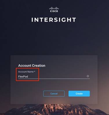
To get started with Cisco Intersight, create a Cisco Intersight account:
Step 1. Visit https://intersight.com/ to create your Intersight account. You must have a valid Cisco ID to create a Cisco Intersight account.
Step 2. Click Create an account.
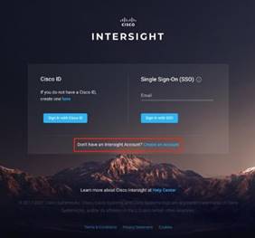
Step 3. Sign-In with your Cisco ID.
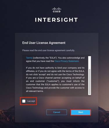
Step 4. Read the End User License Agreement and select I accept and click Next.
Step 5. Provide a name for the account and click Create.
Procedure 2. Set up a Cisco Intersight organization
Optionally, you can define all Cisco Intersight resources under an organization. Note that a default organization already exists. To define a new organization, follow these steps:
Step 1. Log in to the Cisco Intersight portal.
Step 2. Click Settings (the gear icon) and click Settings.
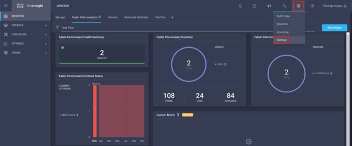
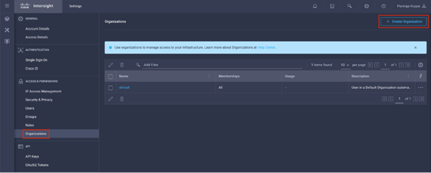
Step 3. Click Organizations in the middle panel.
Step 4. Click Create Organization in the top-right corner.
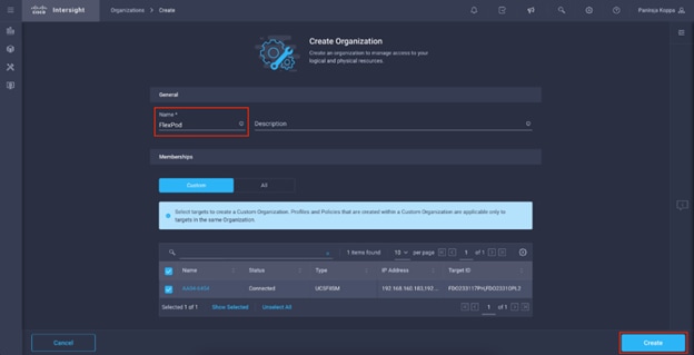
Step 5. Provide a name for the organization (for example, FlexPod).
Step 6. Select the Cisco UCS device if it is already added. Click Create.
Procedure 3. Licensing
In this solution, you will use Cisco Intersight Cloud Orchestrator and Cisco Intersight Service for HashiCorp Terraform. These features are available for users who have the Cisco Intersight Premier license and therefore this licensing tier must be enabled.
Step 1. Log in to the Cisco Intersight portal.
Step 2. Click Settings (the gear icon) and click Licensing.
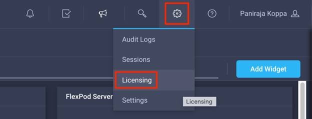
Note: If this is a new account, all servers connected to the UCS Domain will appear under the Base license Tier. If you have purchased Cisco Intersight licenses and have them in your Cisco Smart Account, click Register and follow the prompts to register this Cisco Intersight account to your Cisco Smart Account. Cisco Intersight also offers a one-time 90-day trial of Premier licensing for new accounts. Click Start Trial and then Start to begin this evaluation. The remainder of this section will assume Premier licensing.
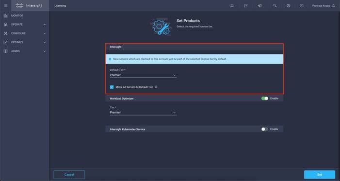
Step 3. From the Licensing Window, click Actions > Set Products.
Step 4. From the drop-down list click Premier for Default Tier in the Intersight licensing section and click Set.
Install Cisco Intersight Assist
Note: Skip this step if you already have an Intersight assist deployed. One Intersight Assist would be enough in the datacenter for all the FlexPod components to communicate with Cisco Intersight.
Cisco Intersight Assist helps you add endpoint devices to Cisco Intersight. Your datacenter could have multiple targets that do not connect directly with Cisco Intersight. Any device that is supported by Cisco Intersight but does not connect directly with it, will need a connection mechanism. Cisco Intersight Assist provides that connection mechanism, and helps you add these targets into Cisco Intersight. It is deployable virtual machine contained within an Open Virtual Appliance (OVA) file format. You can install the appliance on ESXi 6.0 or higher.
A quick summary of requirements and deployment procedure is outlined below. For more information and a detailed deployment procedure, go to: https://www.cisco.com/c/en/us/td/docs/unified_computing/Intersight/cisco-intersight-assist-getting-started-guide/m-overview-of-cisco-intersight-assist.html
Table 8 lists the resource requirements for Cisco Intersight Assist.
Table 8. Cisco Intersight Assist Resource requirements
| Resource Requirements |
Systems Requirements |
|||
|
|
Tiny |
Small |
Medium |
Large |
| vCPU |
8 |
16 |
24 |
48 |
| RAM(GiB) |
16 |
32 |
64 |
96 |
| Storage (GB) |
500GB |
500GB |
500 |
500 |
| Number of servers |
|
|
2000 |
5000 |
| Supported Hypervisors |
|
VMware ESXi 6.5 and higher VMware vSphere Web Client 6.5 and higher |
||
Note: Port 443 need to be open for TCP/UDP traffic and port 80 for TCP.
DNS
You access the Cisco Intersight Assist using the <https://fqdn-of-your-appliance> URL. You must have a PTR record in the DNS entry. Configure DNS with A/PTR and CNAME Alias records as shown below:
Sample A/PTR record: intersightassist (ip.address)
Sample CNAME Alias record: dc-FQDN hostname
Procedure 4. Install Cisco Intersight Assist
Note: If you already have Cisco Intersight Assist deployed, skip the Installation procedure, and navigate to the Upgrade existing Cisco Intersight Assist section.
Step 1. Download the Intersight virtual appliance for VMware from Cisco Software Download portal: https://software.cisco.com/download/home
Step 2. Navigate to Downloads Home > Servers - Unified Computing > Intersight and download the ova file.
Step 3. Log in to VMware vSphere Web Client with administrator credentials. Right-click the Cluster/host and select Deploy OVF Template.
Step 4. On the Deploy OVF Template wizard, in the Source page, specify the source location, and click Next.
Step 5. On the OVF Template Details page, verify the OVF template details and click Next.
Note: No input is necessary.
Step 6. On the Name and Location page, add or edit the Name and Location for the Intersight Assist and click Next.
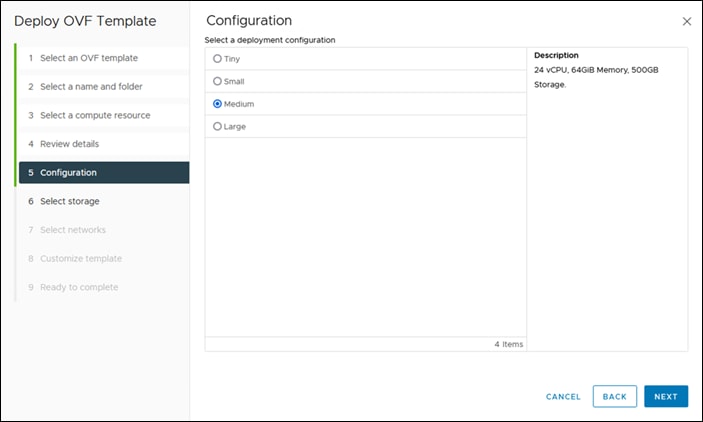
Step 7. On the Deployment Configuration page, select a configuration from the drop-down list and click Next.
Step 8. Choose either Small, Medium or Large deployment configuration since Tiny is only viable for Cisco Intersight Assist used with Cisco Intersight Cloud Orchestrator.
Step 9. On the Storage page, select a destination storage (hard drives) for the VM files in the selected host (ESX station) and click Next. Select the Disk Format for the virtual machine virtual disks. Select Thin Provision to optimize disk usage.
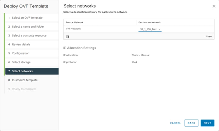
Step 10. On the Network Mapping page, for each network that is specified in the OVF template, select a source network and map it to a destination network and click Next.
Step 11. On the Properties page, customize the deployment properties of the OVF template and click Next.
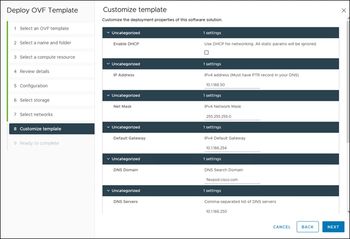
Step 12. On the Ready to complete page, click Finish.
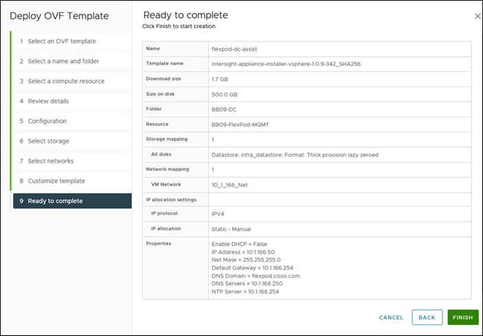
Step 13. After the OVA deployment is complete, and the VM is powered on, wait for a few seconds and then access your VM using the <https://fqdn-of-your-appliance> URL to complete setting up Cisco Intersight Assist.
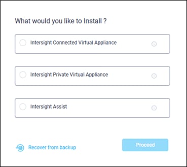
Step 14. Click Cisco Intersight Assist and click Proceed.
Step 15. You will see Connect Intersight Virtual Appliance Wizard, make sure you get the Device ID and Claim Code.
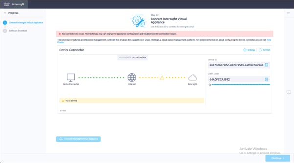
Step 16. Login to Cisco Intersight and click ADMIN > Target > Claim a New Target.
Step 17. Search for Intersight Assist. Select it and click Start.
Step 18. Enter the Device ID and Claim code from Assist. Click Claim. Make sure claim is successful.
Step 19. Return to the Assist Initial Setup Wizard and click Continue.
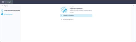
The software download is initiated, and the software packages are installed. The installation process could take up to an hour to complete, depending on the network connection to Cisco Intersight. After the installation is complete, the Cisco Intersight Assist user interface appears.
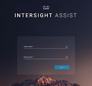
Step 20. Log in to the Cisco Intersight Assist user interface using its FQDN. Enter the username – admin and the password you set at installation.
Procedure 5. Upgrade existing Cisco Intersight Assist
If Cisco Intersight Assist is already deployed for Orchestration, make sure Intersight Assist is always upgraded to latest.
Step 1. Login to Intersight Assist.
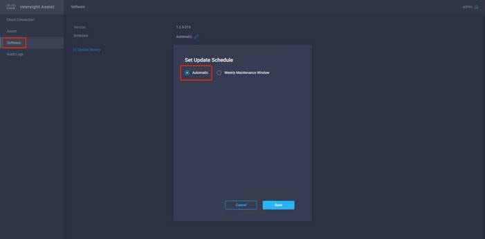
Step 2. From the left navigation pane, click Software.
Step 3. Make sure Software Schedule is set to “Automatic” or set a Weekly Maintenance Window. This will ensure that the upgraded packages are received.
Add FlexPod components to a Cisco Intersight account
Note: Skip this step if all FlexPod components are already added as targets within your Intersight account.
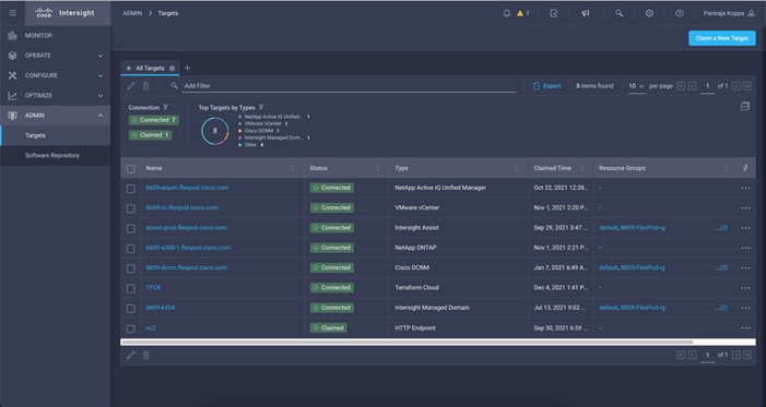
Target
A target is a service that performs management in your environment. Target Configuration specifies the ports Intersight uses to connect with these services. For each target, Intersight communicates with the service via the management protocol that it exposes — The REST API, SMI-S, XML, or some other management transport. Intersight uses this communication to discover the managed entities, monitor resource utilization, and execute actions.
Note: It is required to add all FlexPod components as a Target within Cisco Intersight.
Procedure 6. Claim a target
For more information about claiming target go to: https://intersight.com/help/saas/getting_started/claim_targets#target_claim
FAQs about account setup and claiming a target can be found here: https://intersight.com/help/saas/faqs#general_account_setup_claim_target
Step 1. Log in to Intersight with the Account Administrator, Device Administrator, or Device Technician privileges.
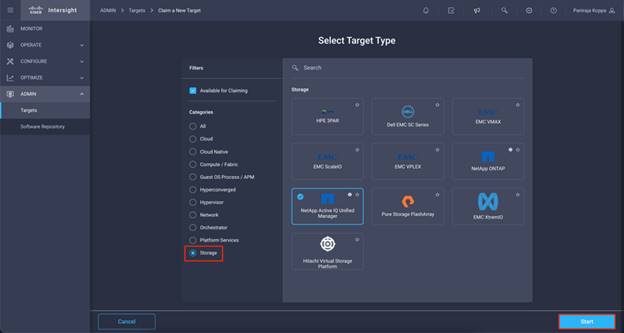
Step 2. Navigate to ADMIN > Targets > Claim a New Target.
Step 3. Click Available for Claiming and select the target type you want to claim. Click Start.
Step 4. Enter the required details and click Claim to complete the claiming process.
Procedure 7. Target Claim for Compute/Fabric
Step 1. Navigate to ADMIN > Targets > Claim a New Target.
Step 2. In Categories, select Compute/Fabric.
Step 3. Click the relevant target and click Start.
Step 4. Enter the applicable Device ID. Endpoint targets connect to the Cisco Intersight portal through a Device Connector that is embedded in the management controller (Management VM for Cisco UCS Director) of each system. The Device Connector provides a secure way for connected targets to send information and receive control instructions from the Cisco Intersight portal, using a secure Internet connection. Table 9 lists the format of the device ID and the device connector location.
Note: Before you gather the Claim Code, ensure that the Device Connector has outbound network access to Cisco Intersight, and is in the “Not Claimed” state.
Step 5. Claim Code—Enter the device claim code and click Claim. You can find this code in the Device Connector.
Step 6. Resource Groups—Select the Resource Group from the list to add it to the Organization.
Note: The Resource Group selection is enabled for the supported targets.
Step 7. Click Claim.
Note: After the targets are claimed, you can view the managed targets in the Targets table view.
Table 9. Device ID Format and Device Connector location
| Targets |
Device ID Format |
Device Connector Location |
| Cisco UCS Server |
Serial Number |
From Admin > Device Connector in Cisco IMC |
| Cisco UCS Domain (UCS Managed) |
Device serial ID of the primary and subordinate Fabric Interconnects |
From Admin > Device Connector in Cisco UCS Manager |
| Cisco UCS Domain (Intersight Managed) |
Device serial ID of the primary and subordinate Fabric Interconnects |
Device Connector in Device Console |
Procedure 8. Target Claim for vCenter
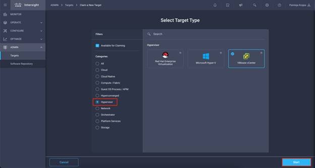
Step 1. Navigate to ADMIN > Targets > Claim a New Target.
Step 2. In Categories, select Hypervisor.
Step 3. Click VMware vCenter and click Start.
Step 4. Claim VMWare vCenter Target.
Step 5. Select the Intersight assist deployed. Provide vCenter details. If Intersight Workflow Optimizer (IWO) is enabled, turn on Datastore Browsing Enabled and Guest Metrics Enabled.
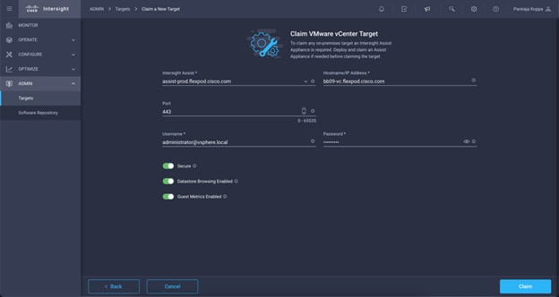
Step 6. Click Claim.
Step 7. After a few minutes, the VMware vCenter will appear in the Targets list. It also can be viewed by clicking Intersight Assist in the Targets list.
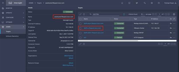
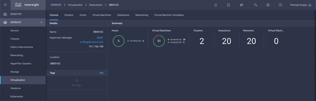
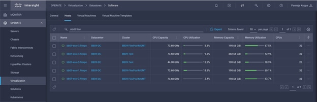
Step 8. Detailed information obtained from the vCenter can now be viewed by navigating to OPERATE > Virtualization.
Procedure 9. Target Claim for NetApp
Step 1. Navigate to ADMIN > Targets > Claim a New Target.
Step 2. In Categories, click Storage.
Step 3. Click NetApp Active IQ Unified Manager and click Start.
Step 4. Select the Intersight assist deployed. Provide details.
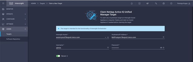
Step 5. Click Claim.
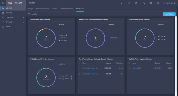
After a few minutes, the NetApp ONTAP Storage will appear in the Storage tab.
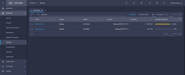
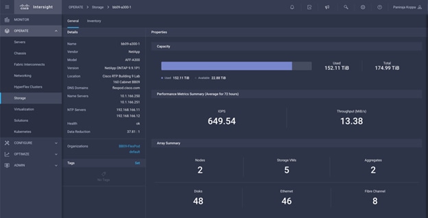
The storage dashboard widgets can also be viewed from Monitoring tab.
Configure Cisco Intersight Service for HashiCorp Terraform
Procedure 1. Connect Cisco Intersight and Terraform Cloud
Step 1. Claim/create a Terraform cloud target by providing relevant Terraform Cloud account details.
Step 2. Create Terraform Cloud Agent target for private clouds so customers install the agent in the datacenter and allow communication with Terraform Cloud.
More information, go to: https://intersight.com/help/saas/features/terraform_cloud/admin
Procedure 2. Generate User Token
As part of adding a target for Terraform Cloud, you must provide the username and API token from the Terraform Cloud settings page.
Step 1. Login to Terraform Cloud and go to User Tokens: https://app.terraform.io/app/settings/tokens
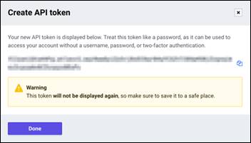
Step 2. Click Create a new API token.
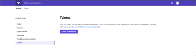
Step 3. Assign a name to remember and save the Token in a secure place.
Procedure 3. Claim Terraform Cloud Target
Step 1. Log in to Intersight with the Account Administrator, Device Administrator, or Device Technician privileges.
Step 2. Navigate to ADMIN > Targets > Claim a New Target.
Step 3. In Categories, click Cloud.
Step 4. Click Terraform Cloud and click Start.

Step 5. Enter a name for the target, your username for the Terraform Cloud, the API token, and a default organization in Terraform Cloud as displayed in the following image.
Step 6. In the Default Managed Hosts, make sure below links are added along with other managed hosts:
● github.com
● github-releases.githubusercontent.com
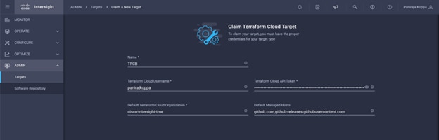
Table 10. Property details for Terraform Cloud Target
| Property |
Essential Information |
| Name |
The name you wish to assign to this Intersight Terraform Cloud integration. You can update this field, if required. |
| Terraform Cloud API Token |
The user API token from a Terraform user who is in the owners team in Terraform. This is the API token that will be used for the other features. The Intersight platform validates if you have the required license for Terraform Cloud on creation. Based on the validation result, the target status is updated in the dashboard (from Claim in progress to Connected). If any validation does not succeed, you will see the Not Connected state. If you see the Not Connected state at. any time, you can see the detail error message when you hover your mouse over the state. You can update this field, if required. |
| Terraform Cloud Username |
The User ID in Terraform Cloud whose token was provided in the API Token field. You can update this field, if required. |
| Default Terraform Cloud Organization Name |
In Terraform Cloud, a Terraform user can have access to more than one organization. Enter the organization with which Intersight will integrate using SSO. And this will be the default organization that will be used when user doesn’t specify one for the other features - Terraform API reverse proxy. Validated by the Intersight platform on creation. Based on the validation result, the target status is updated in the dashboard. If you provide a wrong organization name, the target will display the Not Connected state. You can update this field, if required. |
| Default Managed Hosts |
Optional. A comma separated list of IP addresses, subnets, or CIDRs that is used by the agent to communicate and execute IaC. Whenever a user creates a new agent, values provided in this list will be used to pre-populate the Managed Host field in the Claim Terraform Cloud Agent wizard. Note: Updating Default Managed Hosts will not impact existing agents. |
If successfully implemented, you will see your Terraform Cloud Target displayed in Intersight as displayed in the following image:
Terraform Cloud Agent
To run Terraform configurations in private datacenters that may or may not have direct ingress internet connectivity, Intersight users can enable Terraform Cloud Agent (also referred to as TFC Agent or agent) on Cisco Intersight Assist in the datacenter. The agent is considered to be a global resource within an organization.
You can then invoke deployments on workspaces that are configured in agent mode in Terraform Cloud and the Terraform agents reach the endpoints in private datacenters to perform the required actions.
Terraform Cloud provides a solution for running terraform code in environments which are isolated, on-premises, and/or private. This is done by provisioning an agent called the Terraform Cloud Agent (agent) in the users private environment. The agents are pull based and hence no inbound ports need to be exposed by the private infrastructure.
The Docker image used by the agent is available at the https://hub.docker.com/r/hashicorp/tfc-agent/tags. Intersight maintains and updates the agent images as required in an internal Docker registry. The agent is instantiated as Kubernetes pods in an Intersight Assist Appliance.
Note: Once you install Terraform Cloud Agent through Intersight, it becomes the child target of a Terraform Cloud Target. You will not be able to delete the Terraform Cloud Target till all the child Terraform Cloud Agents are deleted.
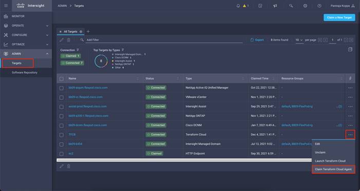
You can use the Terraform Cloud Agent to run the plans in a private datacenter. By selecting the Claim Terraform Cloud Agent in the Action dropdown for the Terraform Cloud target, you can deploy a Terraform Cloud Agent.
Procedure 4. Add Terraform Cloud Agents
Prerequisites
● Terraform Cloud target.
● Claimed Intersight Assist into Intersight before deploying the Terraform Cloud Agent.
Note: You can only claim 5 agents for each Assist.
Note: After creating the connection to Terraform it is time to spin up a Terraform Agent to execute the Terraform code.
Step 1. Click Claim Terraform Cloud Agent from the drop-down list of your Terraform Cloud Target as displayed in the following image:
Step 2. Enter the details for the Terraform Cloud Agent.
Table 11. Property Details for Terraform Agent
| Property |
Essential Information |
| Name |
The name you wish to assign to this Intersight Terraform Cloud Agent. |
| Intersight Assist |
Cisco Intersight Assist in the datacenter where the Terraform Cloud Agent will be deployed. Before claiming an agent target, you must ensure that you have an Assist to claim the agent target. |
| Terraform Cloud Organization |
The organization where the Terraform Cloud Agent will be deployed. The default organization of the Terraform Cloud target is pre-populated for the Agent as well. If not specified, the default TF cloud organization specified in the parent target will be used. |
| Managed Hosts |
This is a list of endpoints that the agent uses to communicate and execute the IaC. This endpoint can either be an IP address, subnet, or a CIDR. The list of endpoints are pre-populated based on the Terraform Cloud Integration’s Default Managed Hosts settings. Users can edit the list before saving. Recommendation: For specific Terraform Providers (for example, Cisco ACI), you may need to configure Managed Hosts with github.com and githubusercontent.com. You can modify the list of Managed Hosts at any time. |
| Terraform Cloud Agent Pool Name |
The agent pool to use for agent deployment. Each Agent is associated with a pool. You can use an existing pool. You can also have the Intersight platform create a new pool for you. |
Figure 10. Configuration details for Terraform Agent
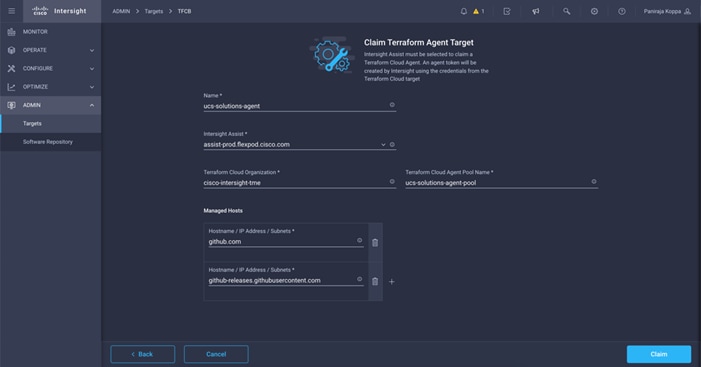
Note: You can update any Terraform Agent property, if the target is in the Not Connected state and has never gone to the Connected state, prior to this state – this scenario is indicative of a token that has not been generated for the Terraform Agent.
Once the agent validation succeeds and an agent token is generated, you are unable to reconfigure the Organization and/or Agent Pool. Successful deployment of a Terraform Agent is indicated with a status of Connected.
After you have enabled and claimed the Terraform Cloud integration, you can deploy one or more Terraform Cloud Agents in Cisco Intersight Assist. The Terraform Cloud Agent is modeled as a child target of the Terraform Cloud target. When you claim the agent target, you will see a message to indicate that the target claim is in progress.
After a few seconds, the target is moved to the Connected state, the Intersight platform routes HTTPS packets from the agent to the Terraform Cloud gateway.
Your Terraform Agent should be correctly claimed and should show up under targets as Connected.
Figure 11. Terraform Agent listed under Targets
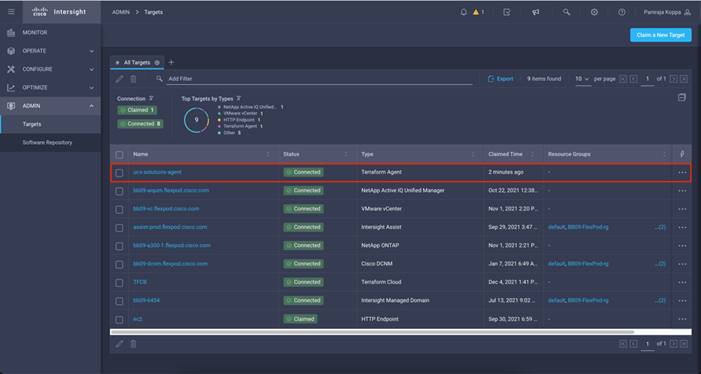
Configure Public Cloud Service Provider
Public Cloud Service Provider environment preparation
The following tables can be used to capture the environment details of your Public Cloud service provider. These parameters will be used for the solution configuration.
Table 12. General information sheet
| AWS information |
Your value |
| AWS access key |
|
| AWS secret key |
|
Table 13. Network information sheet for Connector and CVO deployment as a Single Node or HA in Single Availability Zone
| AWS information |
Your value |
| Region |
|
| VPC |
|
| Subnet |
|
| Security group (if using your own) |
|
Table 14. Network information sheet for CVO deployment as a HA in Multi Availability Zone
| AWS information |
Your value |
| Region |
|
| VPC |
|
| Subnet |
|
| Security group (if using your own) |
|
| Node 1 availability zone |
|
| Node 1 subnet |
|
| Node 2 availability zone |
|
| Node 2 subnet |
|
| Mediator availability zone |
|
| Mediator subnet |
|
| Key pair for the mediator |
|
| Floating IP address for cluster management port |
|
| Floating IP address for data on node 1 |
|
| Floating IP address for data on node 2 |
|
| Floating IP address for data for SVM management |
|
| Route tables for floating IP addresses |
|
Procedure 5. VPC endpoint gateway
A VPC endpoint gateway is required to enable the connection between the VPC and the AWS S3 service. This is used to enable the backup on CVO, an endpoint with the Gateway type.
Step 1. Login to AWS management console and go to VPC.
Step 2. Under Virtual Private Cloud, click Endpoints and Create Endpoint.
Step 3. Select AWS services under Service category and search for ‘s3’.
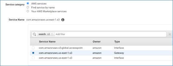
Step 4. Select the Type Gateway, your VPC, and the associated route table.
Step 5. Leave the Policy section to default Full Access, then click Create endpoint. A message stating, “Endpoint created successfully” will be displayed and the status will be marked as “Available.”
Procedure 6. Access the NetApp Cloud Manager
To access the NetApp Cloud Manager and other cloud services you need to sign up on NetApp Cloud Central.
Note: You need an account that has permission to deploy the Connector in your cloud provider directly from Cloud Manager. You can download the Cloud Manager policy from here.
Step 1. Sign up on NetApp Cloud Central to access NetApp’s cloud services.
Step 2. Launch NetApp Cloud Central from your web browser and click Sign Up.
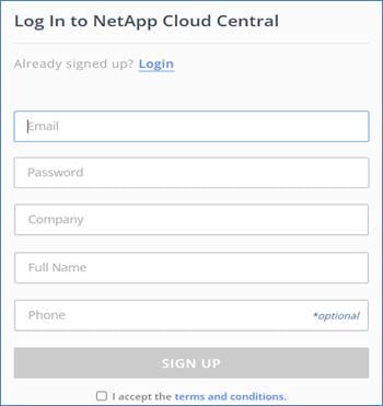
Step 3. Wait for an email from NetApp Cloud Central and click the link to verify the email address.
Step 4. Launch Cloud Manager on the same web browser.
Step 5. Log in using your NetApp Cloud Central credentials.
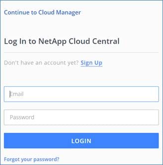
Step 6. On the Fabric View click Go to Cloud Manager.
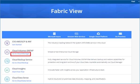
Step 7. When you first access Cloud Manager, you’re prompted to select or create a Cloud Central account. This account provides multi-tenancy and enables you to organize users and resources in isolation workspaces. Provide the account name and click Create Account.
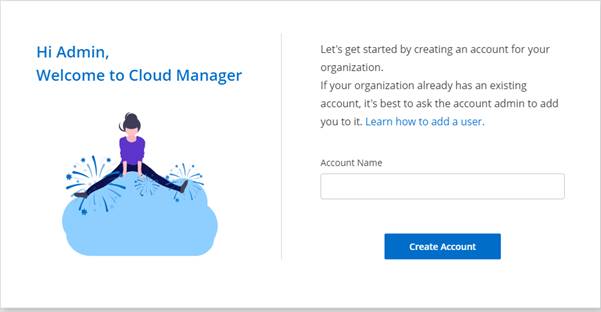
Note: For setting up workspaces and users in the Cloud Central account click here.
Before adding a Cloud Volume ONTAP working environment a Connector needs to be deployed. Cloud Manager will prompt you if you try to create your first CVO working environment without a connector in place.
Note: If you don’t want Cloud Manager to automatically create an IAM role for the Connector, then you’ll need to create your own using this policy
Step 1. Click Add Working Environment.
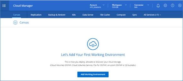
Step 2. Select Amazon Web Services and click Cloud Volume ONTAP, then click Next.
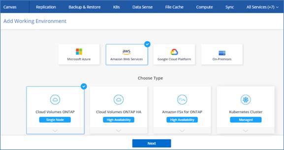
Step 3. On the Add Connector page click Let’s Start.
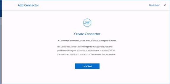
Step 4. Click Next and provide the details.
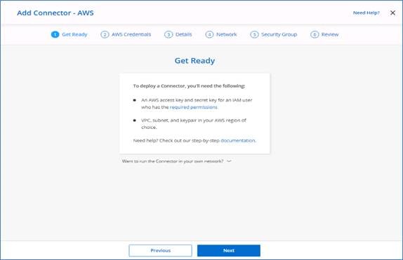
Step 5. Enter AWS Access Key, Secret Key and select the region where you want to deploy the Connector.
Step 6. Provide the Instance name and click the Create role option to let Cloud Manager to create new role.
Step 7. Specify the VPC, subnet, key pair and select Use subnet settings (Disable).
Note: The subnet should have internet connectivity through NAT device or proxy server
Step 8. On the Security Group page create a new security group or can use an existing security group which allow inbound HTTP, HTTPs and SSH access.
Step 9. Review the configuration and click Add. The entire deployment process should take about 5 minutes to complete.
Note: During Connector deployment no other Cloud Manager features will be available
A message stating “Connector deployed successfully” will be displayed on the screen.
Automated Deployment of Hybrid Cloud NetApp Storage
Set up environment prerequisites
The automation of creating CVO clusters, SnapMirror configurations between on-premises volume and Cloud volume, creating a cloud volume etc. are performed using Terraform configuration. These Terraform configurations will be hosted on Terraform Cloud for Business account. Using Intersight Cloud Orchestrator, you will orchestrate tasks like creating workspace in Terraform Cloud for Business account, add all required variables to workspace, execute Terraform Plan and Apply and so on.
For these automation and orchestration tasks, there are few requirements and input data which are described below:
GitHub Repository
You need a GitHub account to host your Terraform code. Intersight Orchestrator will create a new Workspace in the Terraform Cloud for Business account. This workspace will be configured with Version control workflow. For this purpose, we need to keep the Terraform configuration in a GitHub repository and provide it as an input while creating the workspace.
GitHub link below provides the Terraform configuration with various resources. You can fork this repository and make a copy in your GitHub account.
Link: https://github.com/ucs-compute-solutions/cvo_snapmirror
In this repository, provider.tf has definition for the required Terraform provider. Terraform provider for NetApp Cloud Manager is used.
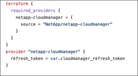
variables.tf has all the variable declarations. The value to these variables are input as Intersight Cloud Orchestrator’s workflow input. This provides a convenient way to pass values to workspace and execute Terraform configuration.
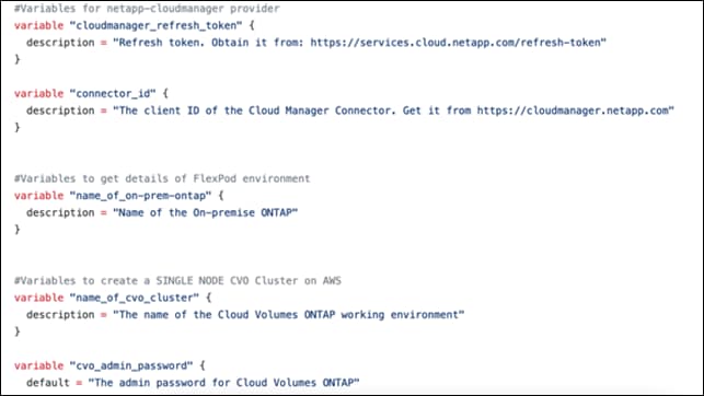
resources.tf defines various resources to add a on-premises ONTAP to working environment, create a single node or highly available CVO cluster on AWS, establish SnapMirror relationship between on-prem and CVO, create a cloud volume on CVO and so on.
Based on your requirement, you can edit this file and make necessary changes. For example, if you like to setup HA for CVO cluster instead of single node CVO, you can un-comment the necessary resource block and comment the resource block to create single node CVO cluster.
You can add additional resource block to create multiple volumes on Cloud Volumes ONTAP or use count or for_each Terraform constructs.
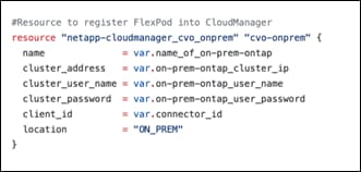
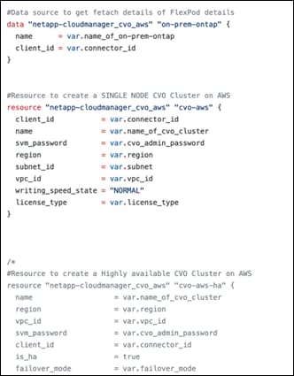
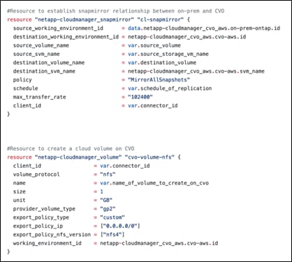
Procedure 8. OAuth Token ID
To connect Terraform workspaces, modules, and policy sets to git repositories containing Terraform configurations, Terraform Cloud needs access to your GitHub.
Add a client and the OAuth Token ID of the client will be used as one of the Intersight Cloud Orchestrator’s workflow input.
Step 1. Login to your Terraform Cloud for Business Account. Navigate to Settings > Providers.
Step 2. Click Add a VCS provider.
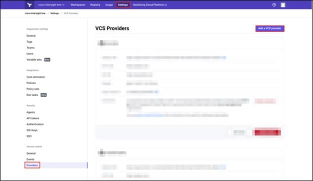
Step 3. Select your version.
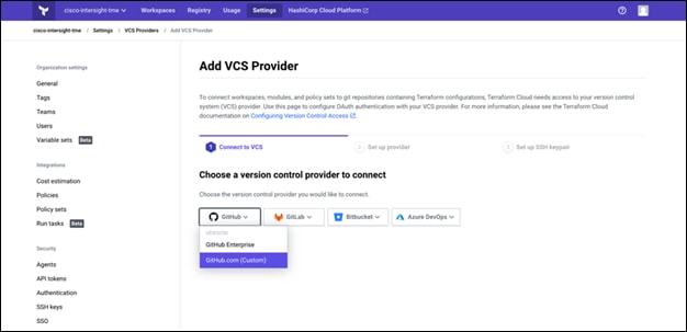
Step 4. Follow the steps under Set up provider:
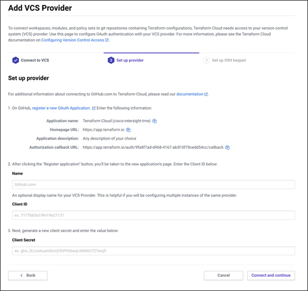
Step 5. You will see the added client in VCS Providers. Make a note of the OAuth Token ID.
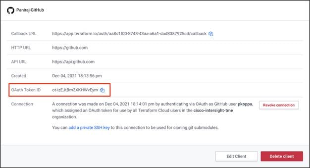
Refresh token for NetApp Cloud Manager API operations
In addition to the web browser interface, Cloud Manager has a REST API that provides software developers with direct access to the Cloud Manager functionality through the SaaS interface. The Cloud Manager service consists of several distinct components that collectively form an extensible development platform. The refresh token enables you to generate access tokens which you add to the Authorization header for each API call.
You don't call any API directly, but the netapp-cloudmanager provider uses this refresh token and translates the Terraform resources into corresponding API calls. You will need to generate refresh token for NetApp Cloud Manager API operations.
You can get token from NetApp Cloud Central. Link: https://services.cloud.netapp.com/refresh-token
Figure 12. Refresh Token Generation
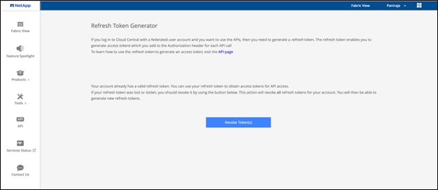
Procedure 9. Cloud Manager Connector ID
You need the client ID of the Cloud Manager Connector to create resources on Cloud Manager like creating CVO cluster, configure SnapMirror, and so on.
Step 1. Login to Cloud Manager: https://cloudmanager.netapp.com/
Step 2. Click Connector.
Cloud Manager listing all the deployed connectors is shown below:
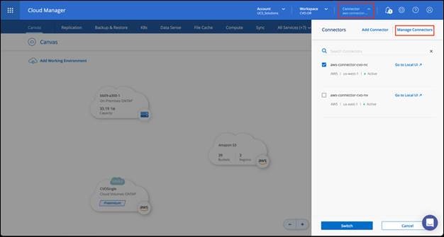
Step 3. Click Manage Connectors.
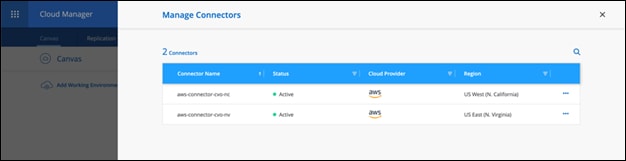
Step 4. Click the ellipses and copy the Connector ID.
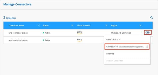
Develop Cisco Intersight Cloud Orchestrator Workflow
Cisco Intersight Cloud Orchestrator is a framework to create and execute complex workflows in Cisco Intersight. A central workflow engine sequences the steps in workflows and automates the execution of workflows. A workflow could be made up of a couple of tasks or could include dozens of them and could also include sub workflows. The Cisco Intersight UI has a workflow designer to visualize a workflow definition and monitor the execution of a workflow.
A workflow is a collection of tasks that are orchestrated to perform certain operations. A workflow is created within an Intersight organization by giving it a name and version. Workflows are uniquely identified by name and version within an organization. When multiple versions of workflows are created, one of them can be marked as the default version. A Cisco Intersight Cloud Orchestrator (ICO) task is a building block of the workflow, and it can perform a simple operation or a sequence of operations including create, update, and delete operations on any target supported by Cisco Intersight. Each IO task is configured by providing the necessary inputs and after a successful execution of the task, the output may be passed onto another task as a required input.
Cisco Intersight provides a library of tasks that you can use to compile a workflow. Each task acts as an independent executable entity and you can use a task in multiple workflows. A task may perform an operation in Cisco Intersight, or it may use the Device Connector at the targets to carry out operations on external devices. A task uses the provided inputs, performs the operation, and produces outputs that can be passed to another task in the workflow. A task typically comprises these elements: Name, Label, Description, Inputs, and Outputs. The task labels and descriptions convey the intent and usage of the tasks. In addition to a library of supported tasks, Intersight Cloud Orchestrator provides a list of sample workflows that you can use to build your workflows.
Requirements
Cisco Intersight Cloud Orchestrator is available in Cisco Intersight if:
● You have installed the Intersight Premier license.
● You are either an Account Administrator, Storage Administrator, Virtualization Administrator, Hyperflex Cluster Administrator, or Server Administrator and have a minimum of one server assigned to you.
● You are a user with either Storage Administrator, Virtualization Administrator, Server Administrator or Workflow Designer privileges assigned, and have a minimum of one server assigned to you.
Workflow Designer
The Workflow Designer helps you create new workflows (as well as tasks and data types) and also edit existing workflows to manage targets in Cisco Intersight.
To launch the Workflow Designer, go to Orchestration > Workflows. A dashboard displays the following details under these tabs; My Workflows, Sample Workflows, and All Workflows:
● Validation Status
● Last Execution Status
● Top Workflows by Execution Count
● Top Workflow Categories
● Number of System Defined Workflows
● Top Workflows by Targets
Using the dashboard, you can create, edit, clone, or delete a tab. To create your own custom view tab, click + and specify a name and then select the required parameters that need to be displayed in the columns, tag columns, and widgets. You can rename the tabs if it does not have a Lock icon.
Under the dashboard is a tabular list of workflows displaying the following information:
● Display Name
● Description
● System Defined
● Default Version
● Executions
● Last Execution Status
● Validation Status
● Last Update
● Organization
The Actions column allows you to do the following actions:
● Execute—Executes the workflow.
● History—Displays workflow execution history.
● Manage Versions—create and manage versions for workflows. See Managing Versions for Workflows later in this document.
● Delete—Delete a workflow.
● Retry—Retry a failed workflow.
Workflow
Creating a workflow consists of the following steps:
● Defining a workflow—you specify the display name, description, and other important attributes.
● Defining workflow inputs and workflow outputs—you can specify which input parameters are mandatory for the workflow execution, and the output(s) generated on successful execution
● Adding workflow tasks—you can add one or more workflow tasks in the Workflow Designer that are needed for the workflow to carry out its function.
● Validate the workflow—you can validate a workflow to ensure that there are no errors in connecting task inputs and outputs.
Procedure 10. Define a workflow
Step 1. Click Orchestration from the left navigation pane.
Step 2. Click Create Workflow. The Create Workflow screen is categorized into the following areas to help you create a workflow:
General Tab
Displays workflow details and also inputs and outputs of the workflow.
You can add a user-friendly short name, reference name, description, and assign an organization to the workflow. You can also specify a version or set a tag to the workflow. In order to categorize your workflow, use the tag key Category and provide an appropriate category value.
Select the following checkboxes to:
● Set as Default Version—Sets this version as the default version for the workflow.
● Retriable—Execute the workflow from the point of a failure or retry the execution of the entire workflow. You can retry the execution of the workflow for up to two weeks after the last update to the workflow.
● Enable Debug Logs—Collects the workflow logs for each task. You can analyze and debug the workflow execution.
● Workflow Inputs—You can click Add Input and add workflow inputs. Each input has a user-friendly display name, a reference name, description, restrictions, and data type. Also, you can set a default value and encrypt it.
● Workflow Outputs—You can click Add Output and add workflow outputs. Each output has a user-friendly display name, a reference name, description, restrictions, and data type. Also, you can encrypt a value and map it to task output.
Designer Tab
Displays the design area where you synthesize your workflow.
Categorized into the following areas to help you create a workflow:
● Tools Area—lists all the tasks, workflows, and operations that are currently available in Intersight. You can drag and drop a task or a workflow to the canvas to create or edit the workflow. You can collapse or expand the Tools area. You can use the Search feature to find a specific task or workflow.
● Design Area—where you can build your workflow. Drag and drop tasks and workflows from the Tools area to this area of the screen. This area includes the following options that you can use while creating the workflow:
◦ Zoom in and Zoom out—Magnify or reduce the view of the workflow.
◦ Auto Align Workflow—Automatically align the workflow tasks in the design area.
◦ Auto Align Selected Workflow Entities—Align selected workflow entities in the design area.
◦ Toggle Task Search—Search for a specific task within the workflow. This is useful when you have several tasks within the workflow.
◦ Auto Connect Selected Workflow Entity—Add the workflow entity in the design area. You can drag and drop a task in between the tasks. The possible locations where the selected task can be added is denoted with + icon.
Mapping Tab
Displays the relationship between the task inputs and the outputs of the selected workflow. Information on workflow inputs and workflow outputs is also displayed.
Expand and collapse the Task Inputs and Task Outputs pane.
Code Tab
Displays the code view of the workflow definition.
Read-only view of the workflow. You can copy the code, use this as a sample to create a workflow using Intersight APIs.
History Tab
Status of the executed/in-progress workflows. This tab appears after executing a workflow.
View workflow execution history, retry or clone a previous execution. The system displays a maximum of 100 instances of the workflow execution. The workflow execution is populated for each version of the workflow. When a workflow is successfully executed, the options for retrying the workflow are not displayed. You can retry a failed workflow only when the Retriable option is enabled in the General tab.
Execute
Launches the Enter Workflow Inputs window. Select the Organization and the Workflow instance name to execute the workflow. For user-created workflows, the organization must match where it was created.
Save Workflow
Validates and saves the workflow. Review validation errors, if any, and rectify them.
Close Designer
Closes the Workflow Designer. Closes the Workflow Designer and displays the table view of available workflows.
Requests
Requests are closely related to workflows. You create requests by running workflows; a request is generated every time you execute a workflow in Cisco Intersight. A request is a process under the control of Cisco Intersight.
You can schedule a workflow for later execution, and Cisco Intersight stores details of completed requests. To view the detailed information of a request, select a request. The following information is displayed in the Requests screen:
● Status—Displays the status of a workflow. Request can have one of several states depending on its execution status:
◦ Running
◦ Blocked (for example, awaiting an approval)
◦ Completed
◦ Failed (a request can fail when one of its component tasks fails to execute properly)
● Details—Displays the request details such as name, request ID, target name and type, source name and type, name of the user who has executed the request along with the start time and end time, and duration of the request.
● Inputs—Displays the workflow input details
● Outputs—Displays the workflow output details
● Execution Flow—Enable Show Additional Details to view the logs, input, and output mapping details of the user-defined workflows. Displays the workflow execution history details similar to the details displayed in the History tab.
Terraform Cloud Integration with ICO
You can use Cisco Intersight Cloud Orchestrator (ICO) to create and execute workflows that call Terraform Cloud (also referred to as TFC) APIs. The Invoke Web API Request task supports Terraform Cloud as a target, and it can be configured with Terraform Cloud APIs using HTTP methods. So, the workflow can have a combination of tasks that calls multiple Terraform Cloud APIs using generic API tasks and other operations. You will need a Premier license to use the ICO feature.
For example, you can have a task in the workflow to run a plan on a Terraform Cloud workspace that creates a VM on a private or public cloud and another task to get the output from the run (for example, IP address of the VM) and display the IP address as the workflow output. Provider credentials are implemented as part of the Terraform Cloud configuration or workspace variables.
You can also invoke Terraform Cloud scripts through ICO Workflows. This mode of operation allows solutions to be incorporated using Intersight Workflows along with Terraform Cloud actions. For example, you can set up a private infrastructure on a VMware Datacenter using Terraform Cloud Agent.
The following Terraform Cloud configurations are available with the supported APIs:
● Terraform Cloud configuration executed on public cloud
● Terraform Cloud configuration executed on a datacenter
TFC-ICO Integration: Out-of-Box ICO Workflows
The out-of-the-box workflows identified below are available to IST users.
Add Terraform Workspace
Below are the inputs for this Workflow:
● Terraform Cloud Target. Select a Terraform cloud target by clicking Select Terraform Cloud Target.
● Terraform Organization Name (Mandatory). Select an organization by clicking Select Terraform Organization Name
● Workspace Name (Mandatory)
● Workspace Description
● Select your workflow (Mandatory)
● Execution Mode indicates whether to use Terraform Cloud as the Terraform execution platform for this workspace:
◦ Remote (default): The plans and applies occur on Terraform Cloud's infrastructure.
◦ Local: The plans and applies occur on platforms you control. Terraform Cloud is only used to store and synchronize the state.
◦ Agent: Terraform Cloud manages the plans and applies your agents execute. If you select Agent Execution Mode, you need to select an agent pool. To select an agent pool, click Select Agent Pool.
● Apply Method indicates whether or not Terraform Cloud should automatically apply a successful Terraform plan.
◦ Manual (default): Requires an operator to confirm the result of the Terraform plan before applying it.
◦ Automatic: Automatically applies changes when a Terraform plan is successful.
● User Interface: Selects the user experience for displaying plan and apply details:
◦ Structured Run Output (default): Enables the advanced run user interface.
◦ Console UI: Uses traditional console-based run logs.
● Share State Globally: A checkbox that shares the state of the workspace with the entire organization.
If you create a Version Control Workflow (VCW) workspace type, the following fields display:
● Repository Name (Mandatory)
● OAuth Token ID (Mandatory)
● Terraform Working Directory
● Automatic Run Triggering Options
● Automatic Speculative Plans
● VCS Branch
● Include the submodules on the clone
Output fields:
● Workspace ID
● Workspace Name
● Organization Name
● Workspace Workflow Type
● Execution Mode
● Agent Pool ID
● Agent Pool name
● User Interface
● Apply Method
● Error message (if workflow execution fails)
The workflow Add Terraform Workspace now supports Rollback. You can use this feature to delete the workspace from the Terraform Cloud.
The system executes the workflow in the following order:
1. Creates the workspace, Workspace Name, under the Organization Terraform Organization Name.
2. Return the Workspace ID or failure reason.
For more information, go to: https://www.terraform.io/docs/cloud/workspaces/creating.html:
Add Terraform Variables
Add regular (non-sensitive) and sensitive Terraform variables in the Terraform workspace.
A workflow execution failure may result in a state where a few variables may be added, and a few may not be added. If you encounter a failure when adding regular (non-sensitive) variables, the workflow fails, and sensitive variables may not be added.
The workflow Add Terraform Variables now supports Rollback. If a workflow fails execution, you can use the Rollback functionality to remove the variables from the Terraform workspace. Only those variables added as part of the current workflow execution would be removed from the Terraform workspace.
After a successful Rollback, the workspace reaches its previous state. Required regular (non-sensitive) and sensitive variables can be added using the Add Terraform Variables workflow again.
Input fields:
● Terraform Cloud Organization Name
● Workspace Name in this organization
● Regular Variables to be added to this workspace
● Sensitive variables to be added to this workspace
● Both Sensitive and Regular (non-sensitive) variables to be added to this workspace
Output Fields:
● Workspace ID (In the case of successful execution)
● Error message (If workflow execution fails)
The system executes the workflow in the following order:
1. Invoke the user-specified workspace for the Terraform Cloud Organization Name.
2. Update the values of existing regular (non-sensitive) variables in the terraform workspace.
3. Update the values of existing sensitive variables in the terraform workspace.
Start New Terraform Plan
To start a new run in the specified workspace.
Input fields:
● Terraform Cloud Organization Name
● Workspace Name in this organization
● Reason for starting plan
● Plan Operation – Can be New Plan or Destroy
Output fields:
● Workspace ID (if workflow is successfully executed)
● Run ID (If workflow is successfully executed)
● Error message (if workflow encounters a failure)
The system executes the workflow in the following order:
1. Invoke the user-specified workspace for the Terraform Cloud Organization Name.
2. Start a new plan.
3. Return the Run ID.
Confirm Terraform Run
Confirm and apply the Run Waiting for confirmation for a Workspace configured with manual apply. Check the execution state of the Run for a Workspace configured with auto apply.
Input fields:
● Terraform Cloud Organization Name
● Workspace Name in this organization
Output fields:
● Workspace ID (if workflow is successfully executed)
● Workspace Name (if workflow is successfully executed)
● Workspace auto-apply (if workflow is successfully executed)
● Run ID (if workflow is successfully executed)
● Run Final State (if workflow is successfully executed)
● Current State Version (if workflow is successfully executed)
● State Output IDs (if workflow is successfully executed)
● Error message (if workflow encounters a failure)
The system executes the workflow in the following order:
1. For the user-specified Terraform workspace, return the ID and the apply configuration of the workspace.
2. For a workspace configured with the manual apply method:
a. Return the ID of the Run which is Planned/Cost-estimated/Policy-checked state.
b. Confirm and apply the Run.
c. Check the execution state of the Run every few minutes until the Run reaches one of the final states.
3. For workspace configured with the auto-apply method:
a. Return the latest run ID.
b. Check the execution state of the Run every few minutes until the Run reaches one of the final states.
4. If the apply is successful, return the current state version and the state output IDs. If apply failed, return the error.
Update Terraform Variable
To update existing regular (non-sensitive) and sensitive Terraform variables in the Terraform workspace.
Input fields:
● Terraform Cloud Organization Name
● Workspace Name in this organization
● Regular (non-sensitive) variables to be updated to this workspace
● Sensitive variables to be updated to this workspace
● Both Sensitive and Regular (non-sensitive) variables to be updated to this workspace
Output fields:
● Workspace ID (if workflow is successfully executed)
● Error message (if workflow encounters a failure)
The system executes the workflow in the following order:
1. Invoke the user-specified workspace for the Terraform Cloud Organization Name.
2. Update the values of existing regular (non-sensitive) variables in the terraform workspace.
3. Update the values of existing sensitive variables in the terraform workspace.
Confirm Terraform User Run
Confirm and apply a Run for a Workspace configured with manual apply. Check the execution state of the Run for a Workspace configured with auto apply.
Note: In this workflow, you do not select either the organization or workspace. You enter the Run ID directly (in the Run ID field) when you enter workflow input.
Input fields:
● Terraform Run ID
Output fields:
● Workspace ID (if workflow is successfully executed)
● Workspace Name (if workflow is successfully executed)
● Workspace auto-apply (if workflow is successfully executed)
● Run ID (if workflow is successfully executed)
● Run Final State (if workflow is successfully executed)
● Current State Version (if workflow is successfully executed)
● State Output IDs (if workflow is successfully executed)
● Error message (if workflow encounters a failure)
The system executes the workflow in the following order:
1. For the user-specified run ID, return the workspace ID and the apply configuration of the workspace.
2. For workspace configured with manual apply method:
a. Confirm and apply the Run.
b. Check the execution state of the Run every few minutes until the Run reaches one of the final states.
3. For workspace configured with auto apply method:
a. Check the execution state of the Run every few minutes until the Run reaches one of the final states.
4. If the apply is successful, return the current state version and the state output IDs. If the apply failed, return the error.
Terraform Workspace Configuration and Execution Mode
Workspaces represent running infrastructure managed in Terraform Cloud, if there is an agent associated with that workspace. Be sure to create the Agent in the pool that is associated with the right workspace so the jobs for this workspace are picked up from the HashiCorp side.
Once configured, any workspace owner may configure their workspace to target the organization's agents.
Note: This kind of a configuration may allow a malicious workspace to access state files, variables, or code from other workspaces that target the same agent or may even access sensitive data on the host running the agent.
Cisco recommends carefully considering the implications of enabling agents within an organization and restricting access of your organization to trusted parties.
Execution Mode
In the Terraform Cloud solution, each user must set the appropriate workspace with an appropriate execution mode. For creating any resource in the on-premises data center, Agent execution mode should be set and the pool in which you created the agent.
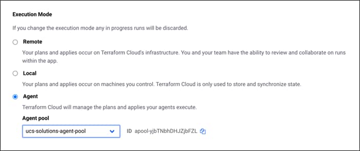
For creating resources in the cloud (Example: creating resource in AWS, NetApp Cloud Manager), execution mode can be set to Remote.
Create Workflows for Disaster Recovery Solution
In the provided example, two workflows are created. However, Cisco Intersight Cloud Orchestrator supports various tasks for Storage, Compute, Virtualization and so on. Based on specific requirements, you can create workflows with simple drag and drop of tasks and have them triggered from Cisco Intersight; the options are endless.
In this section, two sample workflows are created using Workflow Designer; Configure on-premises FlexPod storage and Disaster Recovery Workflow:
● Configure on-premises FlexPod storage workflow will create a Storage Virtual Machine (SVM) on the FlexPod storage, adds NFS interfaces for each of the storage controller, create a new storage export policy mapped to the Storage Virtual Machine so that it can be applied to volumes created on the SVM.
● Disaster Recovery Workflow will create a Volume in the NetApp array, add NFS storage export policy to that volume and map created volume to a datastore in VCenter. The automation of creating CVO clusters and SnapMirror configurations are performed with Terraform using terraform provider for netapp-cloudmanager. For this purpose, we have created tasks within our workflow which creates a workspace, adds all required variables to it, plan and apply on the integrated Terraform Cloud for Business account. This Terraform cloud account is added as target as part of Intersight Service for HashiCorp Terraform.
You also have an option to import sample workflows we created for this solution to your account by importing a JSON file that contains the workflow components. Refer to Importing Cisco built workflow section for details.
Configure on-premises FlexPod storage workflow
The sequence of steps are:
1. Define the workflow. A user-friendly short name for the workflow; Configure on-premises FlexPod storage
2. Define workflow input. The inputs we take for this workflow are:
● Volume Options (Volume Name, Mount Path)
● Volume Capacity
● Datacenter associated with the new datastore
● Cluster on which the datastore will be hosted
● Name for the new datastore to create in VCenter
● Type and version of the new datastore
● Name of the Terraform Organization
● Terraform Workspace.
● Description of the Terraform Workspace
● Variables (Sensitive and Non sensitive) required to execute Terraform configuration.
● Reason for starting the plan
3. Adding workflow tasks. The tasks for FlexPod datacenter configuration include:
● Create a Storage Virtual Machine (SVM)
● Add NFS interface LIF-01 mapping to storage controller 01
● Add NFS interface LIF-02 mapping to storage controller 02
● Create a new storage export policy
● Map the export policy to Storage Virtual Machine
4. Validate the workflow.
Procedure 1. Create Workflow
Step 1. Click Orchestration from the left navigation pane and click Create Workflow.
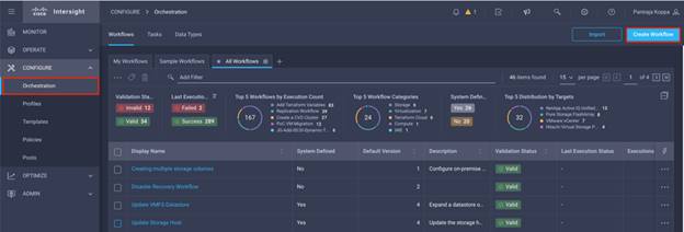
Step 2. In the General tab:
● Provide the display name. (Configure on-premises FlexPod storage)
● Select the organization.
● Set Tags.
● Provide description.
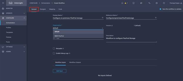
Step 3. Click Save.
Procedure 2. Create a new volume in FlexPod
Step 1. Navigate to the Designer tab and from the Tools section click Tasks.
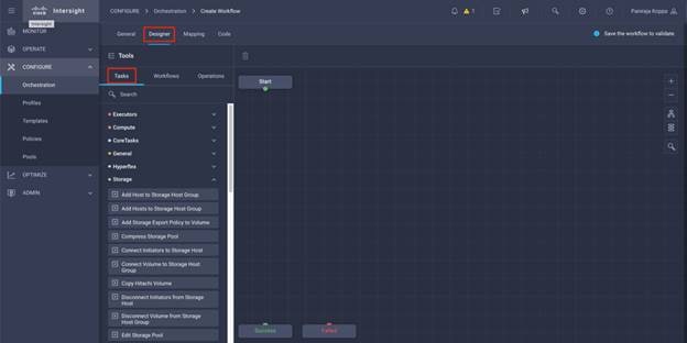
Step 2. From the Tools section in the Design area, drag and drop Storage > New Storage Virtual Machine task into the grid.
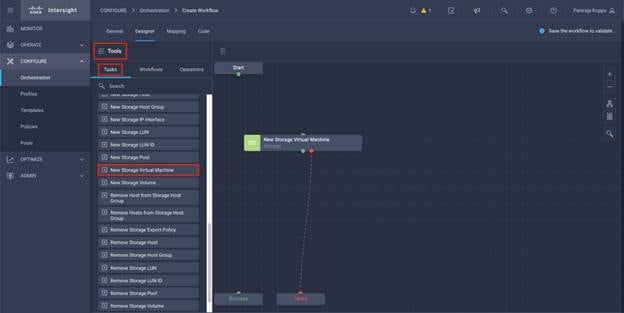
Step 3. Click New Storage Virtual Machine. In the Task Properties area, click the General tab. Optionally, you can change the Name and Description for this task.
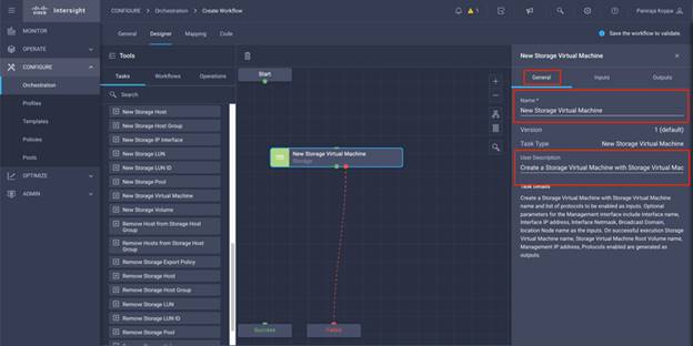
Step 4. In the Task Properties area, click Inputs.
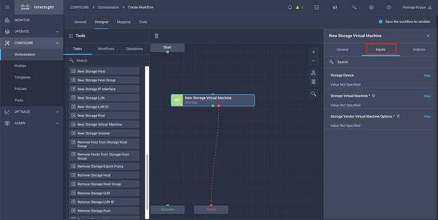
Step 5. Click Map in the input field Storage Device.
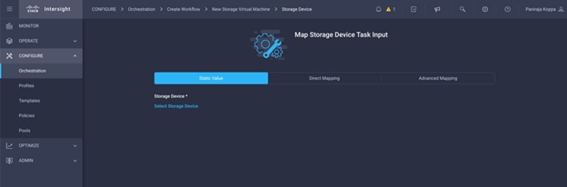
Step 6. Click Static Value and click Select Storage Device.
Step 7. Select the FlexPod Storage added to Intersight account as explained in section Add FlexPod components to Cisco Intersight account.
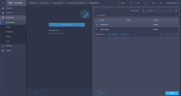
Step 8. Click Map.
Step 9. Click Map in the input field Storage Virtual Machine.
Step 10. Click Direct Mapping and select Workflow Input.
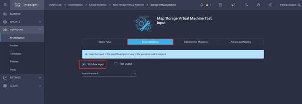
Step 11. Click Input Name and Create Workflow Input.
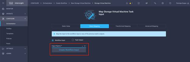
Step 12. In the Add Input wizard:
● Provide a Display Name and Reference Name (Optional)
● Make sure for Type, String is selected
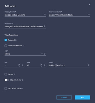
Step 13. Click Set Default Value and Override.
Step 14. Click Required.
Step 15. Provide a default value for Storage Virtual Machine.
Step 16. Click Add.
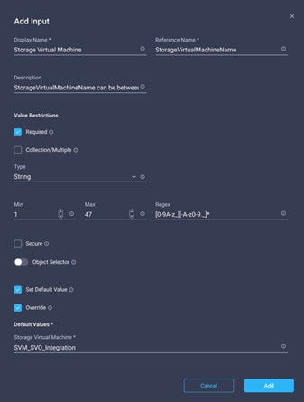
Step 17. Click Map.
Step 18. Click Map in the input field Storage Virtual Machine Options.
Step 19. Click Direct Mapping and select Workflow Input.
Step 20. Click Input Name and Create Workflow Input.
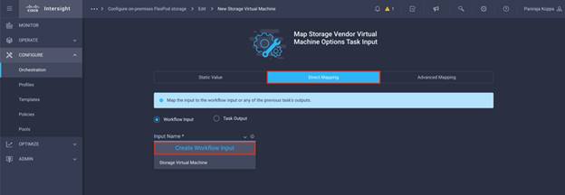
Step 21. In the Add Input wizard:
● Provide a Display Name and Reference Name (Optional)
● Click Required
● Make sure for Type, Storage Vendor Virtual Machine Options is selected
● Click Set Default Value and Override
● Select Platform Type as NetApp Active IQ Unified Manager
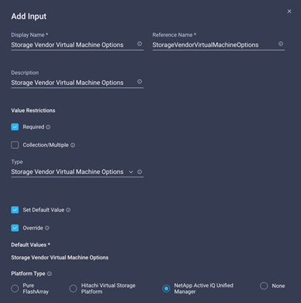
● Provide all configuration details for Storage Virtual Machine
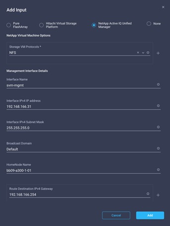
● Click Add.
Step 22. Click Map.
Step 23. Use Connector and connect between Start and New Storage Virtual Machine tasks and click Save.
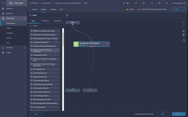
Ignore the error for now. The error is shown because there is no connectivity between tasks New Storage Virtual Machine and Success which is required to specify the successful transition.
This completes the first task of provisioning a new Storage Virtual Machine. Next, you’ll add interfaces to the created Storage Virtual Machine and enable NFS access.
Procedure 3. Add interfaces for NFS access
You will create two logical interfaces (LIFs) mapped to each of the storage controller node.
Step 1. Go to the Designer tab and click Tasks from Tools section.
Step 2. Drag and drop Storage > New Storage IP Interface task from the Tools section in the Design area.
Note: In this example, we provided static values to configure the interface name, its IP, and other interface configurations. If required, you can enter Workflow input as described in the previous task of creating storage virtual machine.
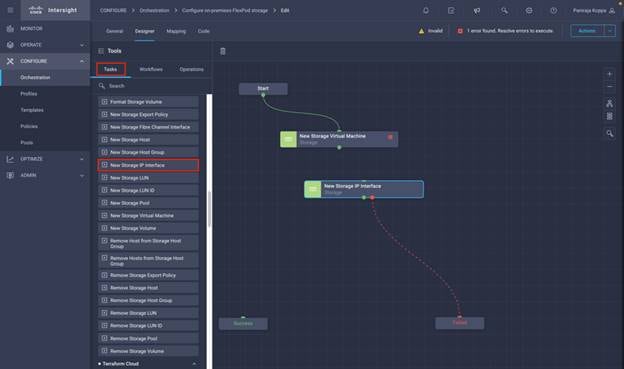
Step 3. Click New Storage IP Interface. In the Task Properties area, click the General tab. Optionally, you can change the Name and Description for this task. In this example, we changed the name of the task to Add NFS LIF - 01.
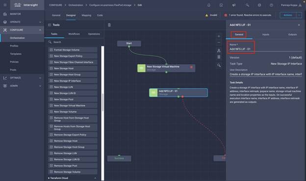
Step 4. Use Connector and connect between New Storage Virtual Machine and Add NFS LIF – 01 tasks.
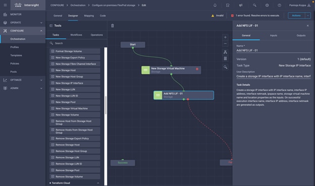
Step 5. In the Task Properties area, click Inputs.
Step 6. Click Map in the input field Storage Device.
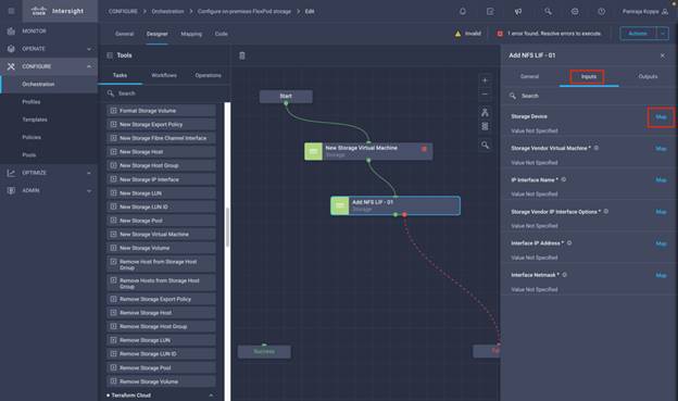
Step 7. Click Static Value and click Select Storage Device.
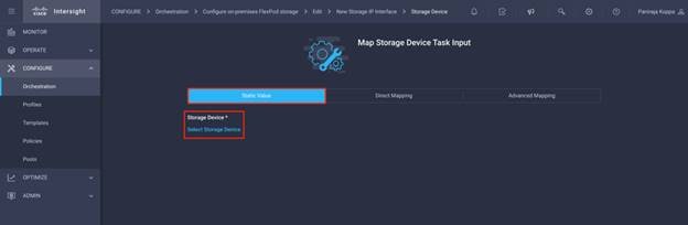
Step 8. Click the FlexPod Storage added to Intersight account as explained in section Add FlexPod Components to Intersight Account.
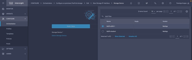
Step 9. Click Map.
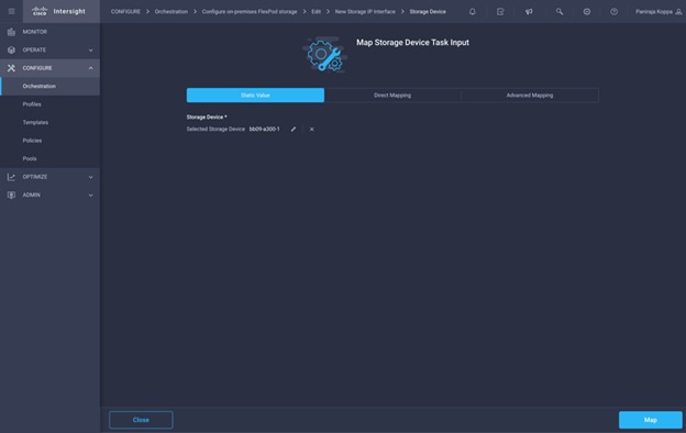
Step 10. Click Map in the input field Storage Vendor Virtual Machine.
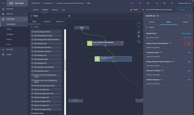
Step 11. Click Direct Mapping and click Task Output.
Step 12. Click Task Name and click the task New Storage Virtual Machine
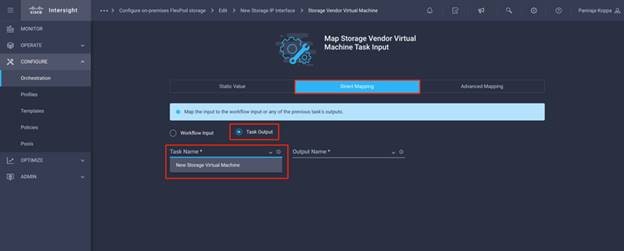
Step 13. Click Output Name and click the output Storage Virtual Machine.
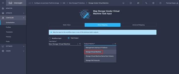
Step 14. Click Map.
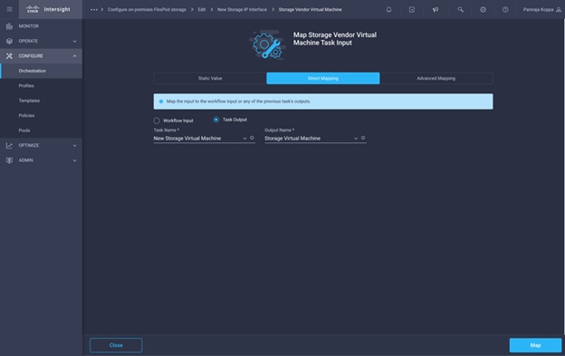
Step 15. Click Map in the input field IP Interface Name.
Step 16. Click Static Value and input the name for the first interface.
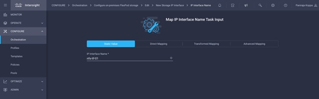
Step 17. Click Map.
Step 18. Click Map in the input field Storage Vendor IP Interface Options.
Step 19. Click Static Value and make sure NetApp Active IQ Unified Manager is selected as Platform Type.
Step 20. The Input node to which the LIF is mapped in the Location Home Node, Port number in the Location Home Port, and the Location Broadcast Domain contains the home port of the logical interface. Click NFS for Storage VM Protocols.
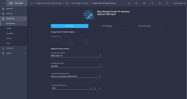
Step 21. Click Map.
Step 22. Click Map in the input field Interface IP Address.
Step 23. Click Static Value and input the IP address for the first interface.

Step 24. Click Map.
Step 25. Click Map in the input field Interface Netmask.

Step 26. Click Map.
Step 27. Click Save.
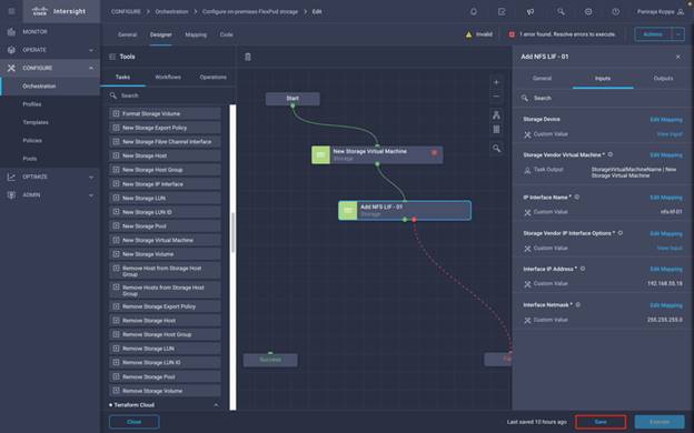
Note: This completes the task of adding the first interface. Next, you will create another interface mapped to second storage controller node.
Step 28. Repeat steps 1 - 27 to create another interface and map it to the second storge controller node. Make sure task name, interface name, IP address are different. Use Connector and connect between tasks Add NFS LIF - 01 and Add NFS LIF - 02
Task Name:
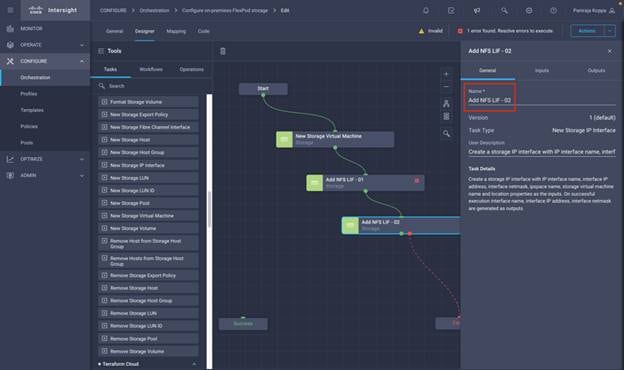
Interface Name:
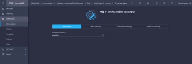
Interface Options:
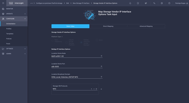
Interface IP Address:

Step 29. Click Save to save the workflow.
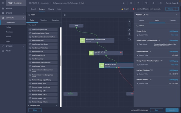
Note: This completes the task of adding two interfaces. Next, create a storage export policy with storage virtual machine name, export policy name, Client Match List, Superuser Security Type, list of protocols, list of Read Only export policy rules, list of Read Write export policy rules as the inputs. On successful execution the name of the export policy created is generated as output.
Procedure 4. Create a new Storage Export policy
Step 1. Go to the Designer tab and click Workflows from Tools section.
Step 2. Drag and drop Storage > New Storage Export Policy task from the Tools section on the Design area.
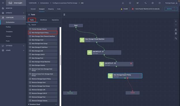
Step 3. Click New Storage Export Policy. In the Task Properties area, click the General tab. Optionally, you can change the Name and Description for this task.
Step 4. Use Connector and connect between tasks Add NFS LIF – 02 and New Storage Export Policy.
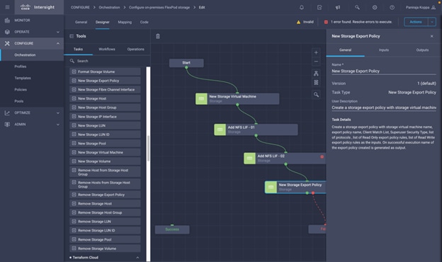
Step 5. In the Task Properties area, click Inputs.
Step 6. Click Map in the input field Storage Device.
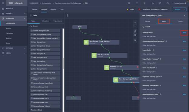
Step 7. Click Static Value and click Select Storage Device.
Step 8. Click the FlexPod Storage added to Intersight account as explained in section Add FlexPod Components to Cisco Intersight account.
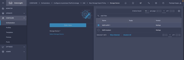
Step 9. Click Map.
Step 10. Click Map in the input field Storage Vendor Virtual Machine.
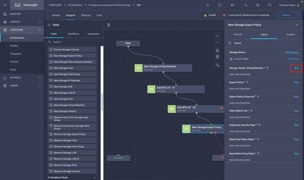
Step 11. Click Direct Mapping and click Task Output.
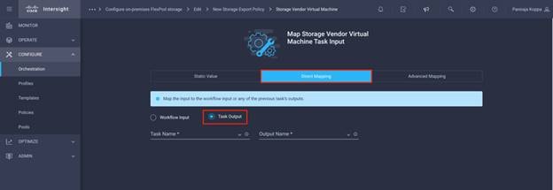
Step 12. Click Task Name and click New Storage Virtual Machine.
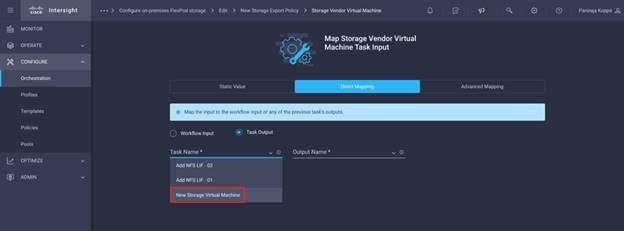
Step 13. Click Output Name and click Storage Virtual Machine.
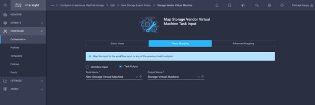
Step 14. Click Map.
Step 15. Click Map in the input field Export Policy.
Step 16. Click Static Value and input the storage export policy name.
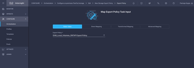
Step 17. Click Map.
Step 18. Click Map in the input field Export Policy Protocols.
Step 19. Click Static Value. Click Export Policy Protocols and select NFS.
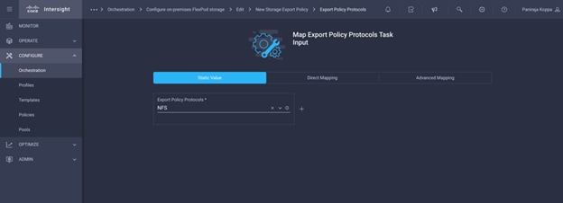
Step 20. Click Map.
Step 21. Click Map in the input field Client Match List.
Step 22. Click Static Value. Input the list of the match strings specifying the client or clients to which the export rule applies.
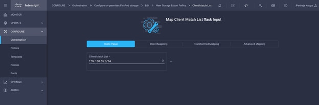
Step 23. Click Map.
Step 24. Click Map in the input field Superuser Security Type.
Step 25. Click Static Value. Click Superuser Security Type and click sys.

Step 26. Click Map.
Step 27. Click Map in the input field Read Only Policy Rules.
Step 28. Click Static Value. Click Read Only Policy Rules and click sys.
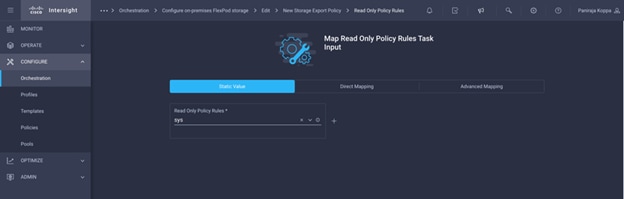
Step 29. Click Map.
Step 30. Click Map in the input field Read Write Policy Rules.
Step 31. Click Static Value. Click Read Write Policy Rules and click sys.
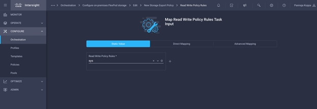
Step 32. Click Map.
Step 33. Click Save.
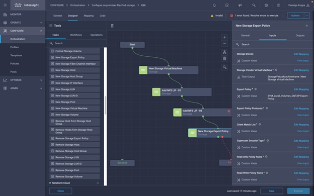
Note: This completes the task of creating a storage export policy for the Storage Virtual Machine. The last task of this workflow is to add this storage export policy to a volume with storage virtual machine name, volume name, and export policy name as the inputs. On successful execution, the volume name and export policy added are generated as outputs.
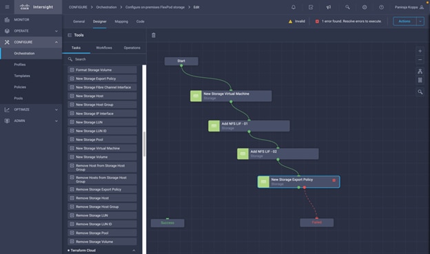
Procedure 5. Add Storage Export Policy to Volume
Step 1. Go to the Designer tab click Workflows from the Tools section.
Step 2. Drag and drop Storage > Add Storage Export Policy to Volume from the Tools section in the Design area.
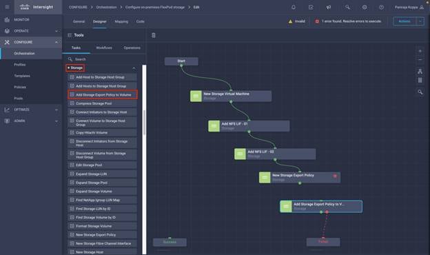
Step 3. Click Add Storage Export Policy to Volume. In the Task Properties area, click the General tab. Optionally, you change the Name and Description for this task.
Step 4. Use Connector and connect between tasks New Storage Export Policy and Add Storage Export Policy to Volume.
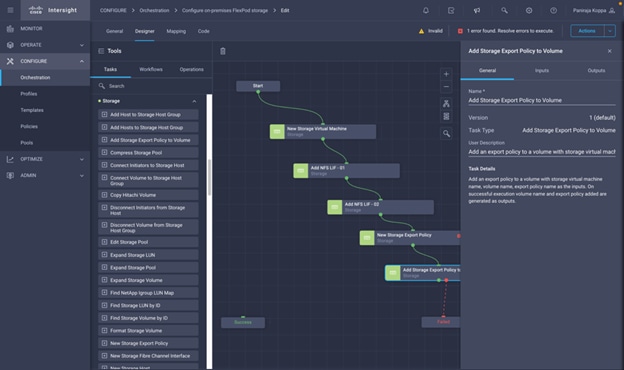
Step 5. In the Task Properties area, click Inputs.
Step 6. Click Map in the input field Storage Device
Step 7. Click Static Value and click Select Storage Device.
Step 8. Click the FlexPod Storage added to the Intersight account as explained in section Add FlexPod Components to Cisco Intersight account.

Step 9. Click Map.
Step 10. Click Map in the input field Storage Vendor Virtual Machine.
Step 11. Click Direct Mapping and click Task Output.
Step 12. Click Task Name and select New Storage Virtual Machine.
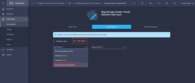
Step 13. Click Output Name and select Storage Virtual Machine.
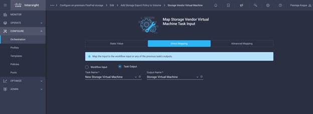
Step 14. Click Map.
Step 15. Click Map in the input field Volume.
Step 16. Click Direct Mapping and click Task Output.
Step 17. Click Task Name and select New Storage Virtual Machine.
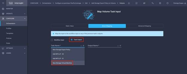
Step 18. Click Output Name and select Storage Virtual Machine Root Volume.
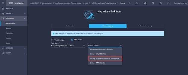
Step 19. Click Map.
Step 20. Click Map in the input field Export Policy.
Step 21. Click Direct Mapping and click Task Output.
Step 22. Click Task Name and select New Storage Export Policy.
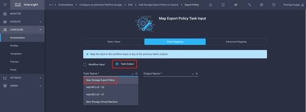
Step 23. Click Output Name and select Export Policy.
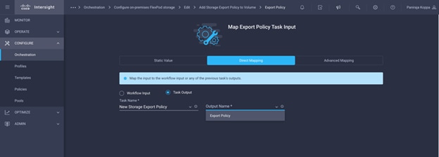
Step 24. Click Map.
Step 25. Click Save.
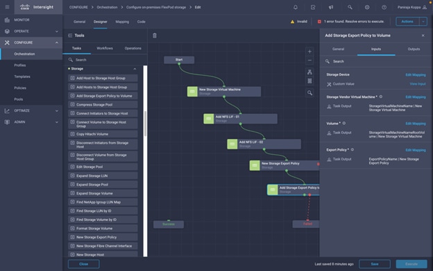
Step 26. Use Connector and connect between tasks Add Storage Export Policy to Volume and Success.
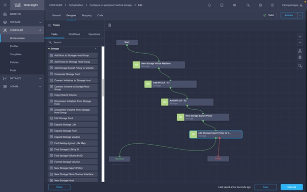
Step 27. From each task’s failure output, connect to Failed.
Step 28. Click Auto Align Workflow.
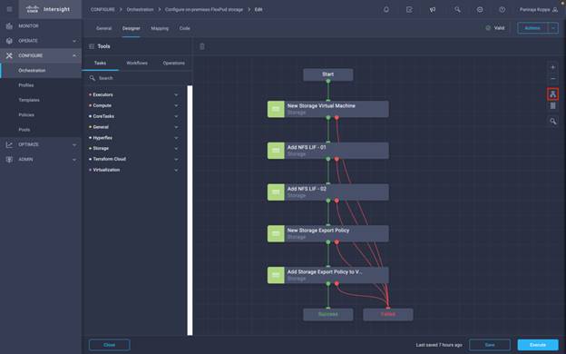
Step 29. Click Save.
Note: This completes the creation of the first workflow of configuring on-premises FlexPod storage. Next, you will create the Disaster Recovery Workflow.
Disaster Recovery Workflow
The sequence of steps are:
1. Define the workflow.
● A user-friendly short name for the workflow, such as Disaster Recovery Workflow
2. Define workflow input.
● The inputs we take for this workflow are:
◦ Volume Options (Volume Name, Mount Path)
◦ Volume Capacity
◦ Datacenter associated with the new datastore
◦ Cluster on which the datastore will be hosted
◦ Name for the new datastore to create in VCenter
◦ Type and version of the new datastore
◦ Name of the Terraform Organization
◦ Terraform Workspace.
◦ Description of the Terraform Workspace
◦ Variables (Sensitive and Non sensitive) required to execute Terraform configuration.
◦ Reason for starting the plan
3. Add workflow tasks.
● The tasks related to operations in FlexPod datacenter include:
◦ Create Volume in FlexPod
◦ Add Storage Export Policy to the created volume
◦ Map the newly created volume to a datastore in VCenter
● The tasks related to Creating CVO cluster and adding:
◦ Add Terraform Workspace
◦ Add Terraform Variables
◦ Add Terraform Sensitive Variables
◦ Start New Terraform Plan
◦ Confirm Terraform Run
4. Validate the workflow.
Procedure 6. Create the Workflow
Step 1. Click Orchestration from the left navigation pane and click Create Workflow.
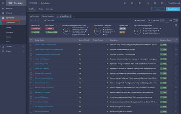
Step 2. In the General tab:
● Provide the display name. (Disaster Recovery Workflow)
● Select the organization
● Set Tags
● Provide a description
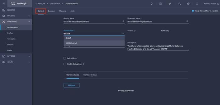
Step 3. Click Save.
Procedure 7. Create a new volume in FlexPod
Step 1. Go to the Designer tab and click Tasks from Tools section.
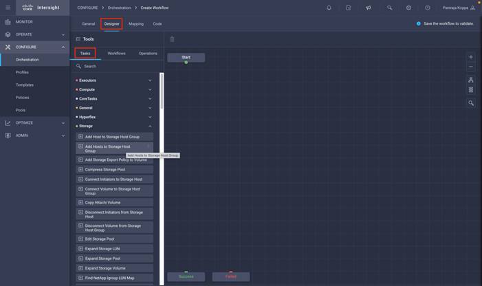
Step 2. Drag and drop Storage > New Storage Volume task from the Tools section in the Design area.
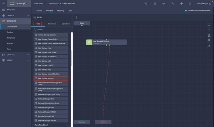
Step 3. Click New Storage Volume. In the Task Properties area, click the General tab. Optionally, you can change the Name and Description for this task. In this example, the name of the task is Create Volume in FlexPod.
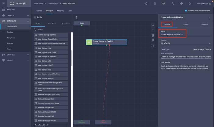
Step 4. In the Task Properties area, click Inputs.
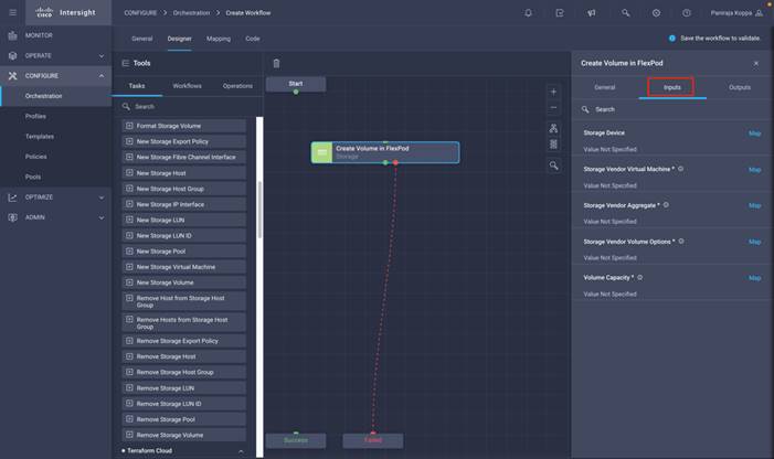
Step 5. Click Map in the input field Storage Device.
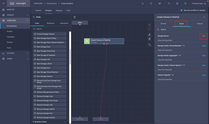
Step 6. Click Static Value and click Select Storage Device.
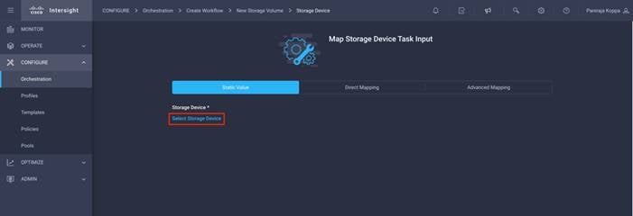
Step 7. Click the Storage Target added as explained in section Add FlexPod Components to Cisco Intersight account and click Select.
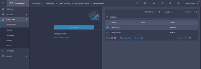
Step 8. Click Map.
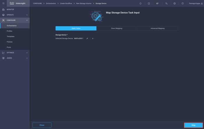
Step 9. Click Map in the input field Storage Vendor Virtual Machine.
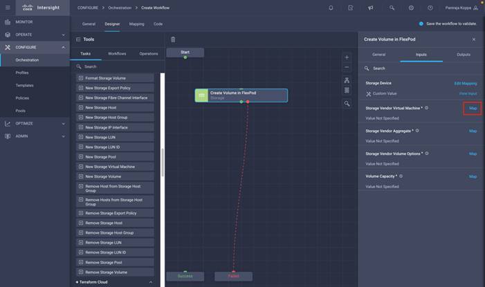
Step 10. Click Static Value and click Select Storage Virtual Machine. Select the Storage Virtual Machine where the volume needs to be created and click Select.
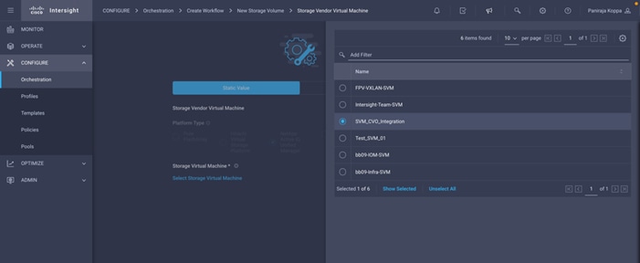
Step 11. Click Map.
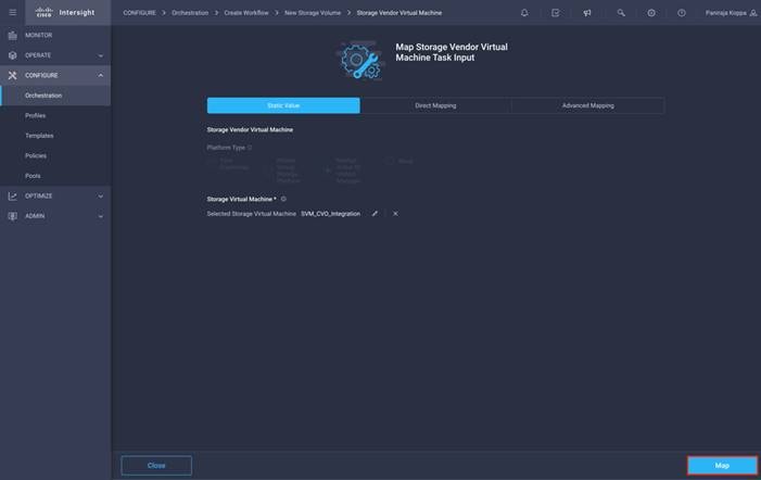
Step 12. Click Map in the input field Storage Vendor Aggregate.
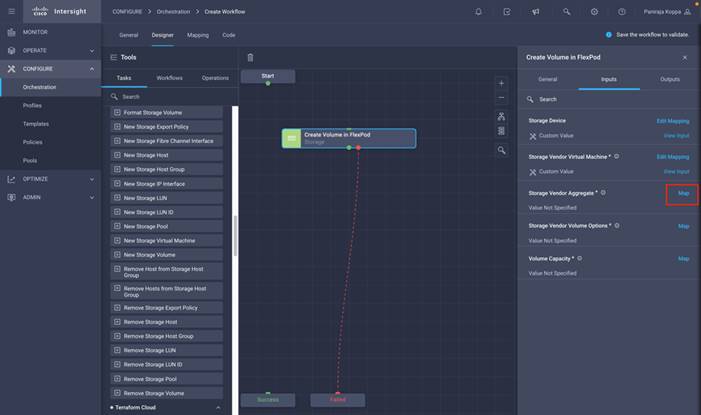
Step 13. Click Static Value and click Select Storage Aggregate. Click the Aggregate and click Select.
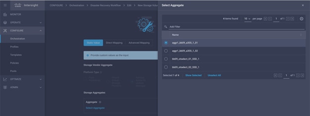
Step 14. Click Map.
Step 15. Click Map in the input field Storage Vendor Volume Options.
Step 16. Click Direct Mapping and click Workflow Input.
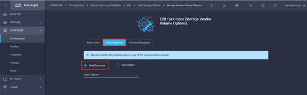
Step 17. Click Input Name and Create Workflow Input.
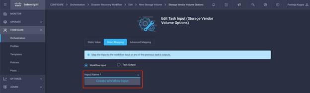
Step 18. In the Add Input wizard:
● Provide a Display Name and Reference Name (Optional)
● Make sure for Type, Storage Vendor Volume Options is selected
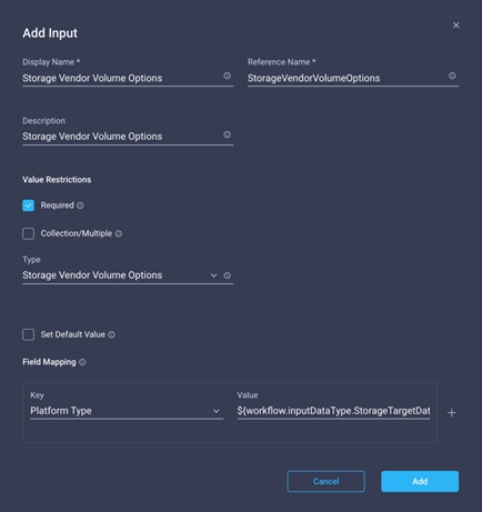
● Click Set Default Value and Override.
● Click Required.
● Click Platform Type as NetApp Active IQ Unified Manager.
● Provide a default value for the volume to create in Volume.
● Click NFS. If NFS is set, NFS volume will be created and if set to false, SAN volume will be created.
● Provide a Mount Path.
● Click Add.
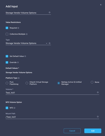
Step 19. Click Map.
Step 20. Click Map in the input field Volume Capacity.
Step 21. Click Direct Mapping and click Workflow Input.
Step 22. Click Input Name and Create Workflow Input.
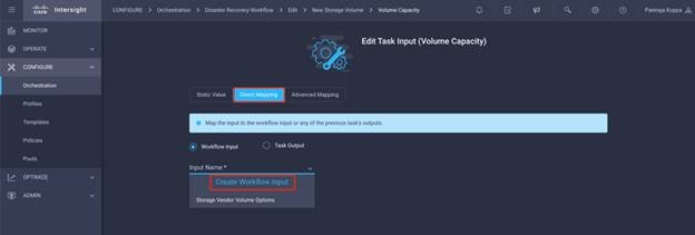
Step 23. In the Add Input wizard:
● Provide a Display Name and Reference Name (Optional)
● Click Required
● Make sure for Type, Storage Capacity is selected
● Click Set Default Value and Override
● Provide a default value for the volume size and unit
● Click Add
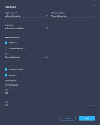
Step 24. Click Map.
Step 25. Use Connector and connect between Start and Create Volume in FlexPod tasks and click Save.
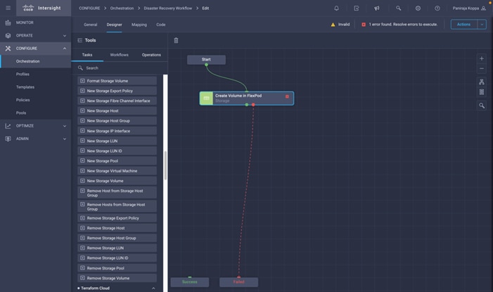
Note: Ignore the error for now. The error displays because there is no connectivity between tasks Create Volume in FlexPod and Success which is required to specify the successful transition.
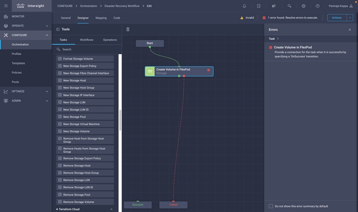
Note: This completes the creation of the first task of provisioning a new volume in FlexPod. Next, you will add an export policy to created volume with storage virtual machine name, volume name, and export policy name as the inputs.
Procedure 8. Add Storage Export Policy
Step 1. Go to the Designer tab and click Tasks from the Tools section.
Step 2. Drag and drop Storage > Add Storage Export Policy to Volume task from the Tools section in the Design area.
Step 3. Click Add Storage Export Policy to Volume. In the Task Properties area, click the General tab. Optionally, you can change the Name and Description for this task. In this example, the name of the task is Add Storage Export Policy.
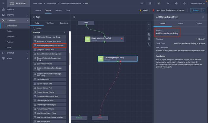
Step 4. Use Connector and connect between tasks Create Volume in FlexPod and Add Storage Export Policy and click Save.
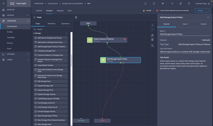
Step 5. In the Task Properties area, click Inputs.
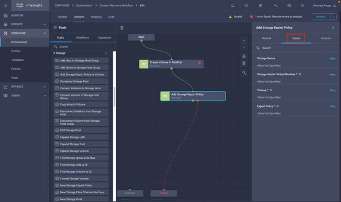
Step 6. Click Map in the input field Storage Device.
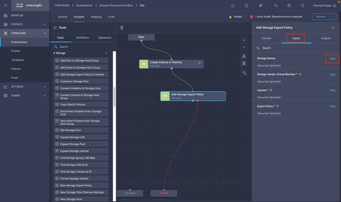
Step 7. Click Static Value and click Select Storage Device. Select the same storage target added while creating previous task of creating a new storage volume.
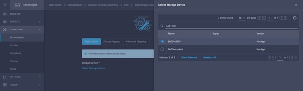
Step 8. Click Map.
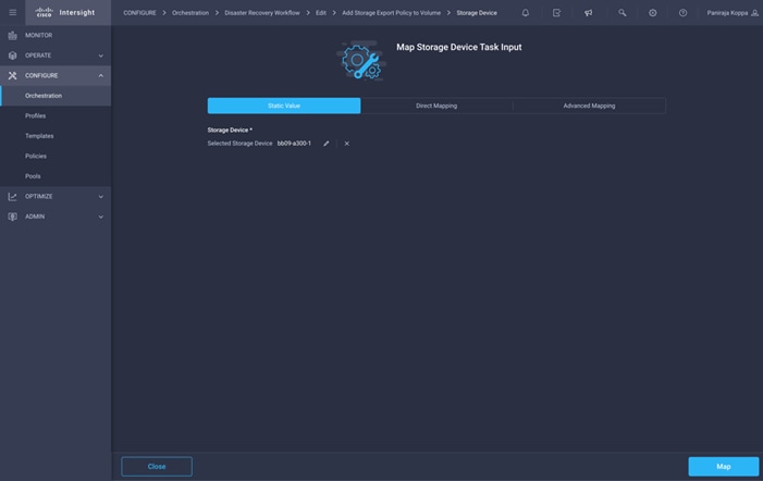
Step 9. Click Map in the input field Storage Vendor Virtual Machine.
Step 10. Click Static Value and click Select Storage Virtual Machine. Select the same storage Virtual Machine added while creating previous task of creating a new storage volume.
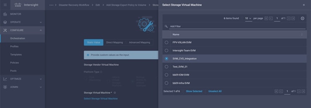
Step 11. Click Map.
Step 12. Click Map in the input field Volume.
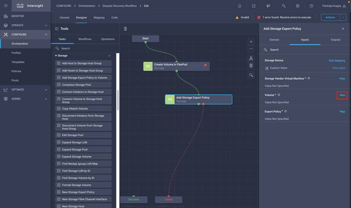
Step 13. Click Direct Mapping and click Task Output.
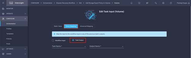
Step 14. Click Task Name and click Create Volume in FlexPod. Click Output Name and click Volume.
Note: In Cisco Intersight Cloud Orchestrator, you can provide task output of a previous task as input to a task. In this example, the Volume details were provided from the created Create Volume in FlexPod as an input to task Add Storage Export Policy.
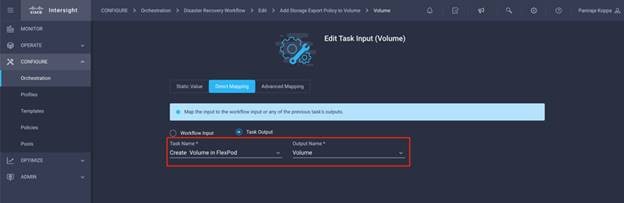
Step 15. Click Map.
Step 16. Click Map in the input field Export Policy.
Step 17. Click Static Value and click Select export Policy. Select the export Policy created.
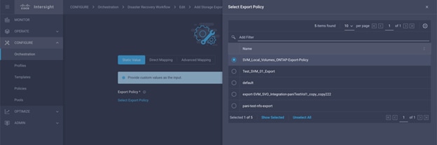
Step 18. Click Map and click Save.
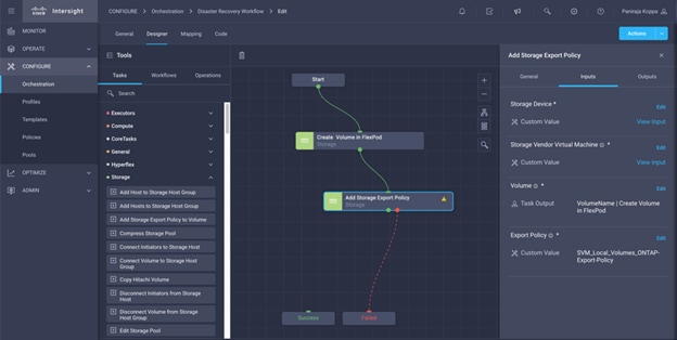
Note: This completes the creation of adding an export policy to the volume. Next, you will create a new datastore mapping the created volume.
Procedure 9. Map FlexPod volume to datastore
Step 1. Go to the Designer tab and click Tasks from Tools section.
Step 2. Drag and drop Virtualization > New Hypervisor Datastore task from the Tools section in the Design area.
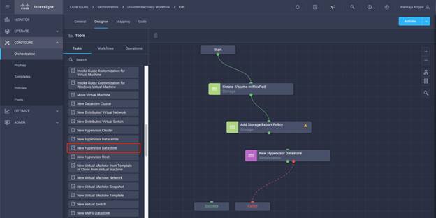
Step 3. Use Connector and connect between tasks Add Storage Export Policy and New Hypervisor Datastore tasks and click Save.
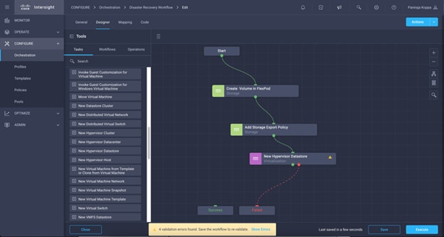
Step 4. Click New Hypervisor Datastore. In the Task Properties area, click the General tab. Optionally, you can change the Name and Description for this task. In this example, the name of the task is Map volume to Datastore.
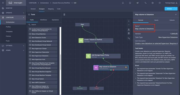
Step 5. In the Task Properties area, click Inputs.
Step 6. Click Map in the input field Hypervisor Manager.
Step 7. Click Static Value and click Select Hypervisor Manager. Click the VMWare VCenter target explained in section Add FlexPod Components to Cisco Intersight account.
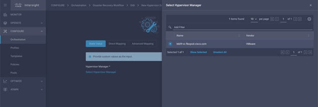
Step 8. Click Map.
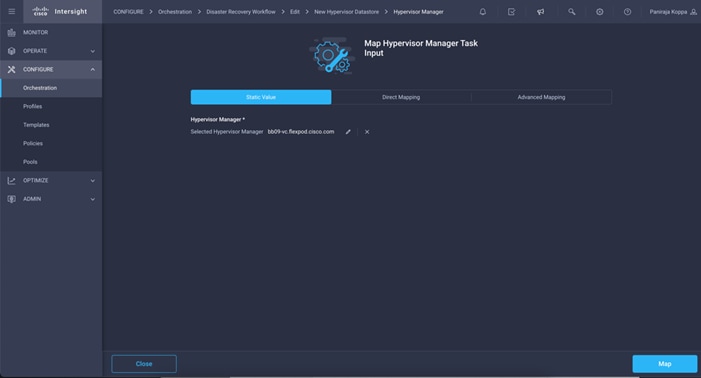
Step 9. Click Map in the input field Datacenter. This is the datacenter associated with the new datastore.
Step 10. Click Direct Mapping and click Workflow Input.
Step 11. Click Input Name and Create Workflow Input.
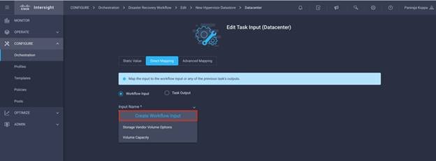
Step 12. In the Add Input wizard:
● Provide a Display Name and Reference Name (Optional)
● Make sure for Type, Datacenter is selected
● Click Set Default Value and Override
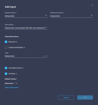
● Click Select Datacenter
● Click the datacenter associated with the new datastore.
● Click Select
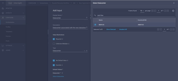
● Click Add
Step 13. Click Map.
Step 14. Click Map in the input field Cluster.
Step 15. Click Direct Mapping and click Workflow Input.
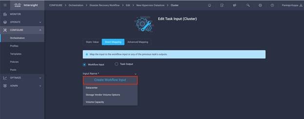
Step 16. In the Add Input wizard:
● Provide a Display Name and Reference Name (Optional)
● Click Required
● Make sure for Type, Cluster is selected
● Click Set Default Value and Override
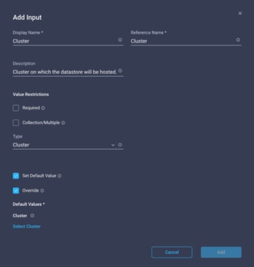
● Click Select Cluster
● Click the cluster associated with the new datastore.
● Click Select
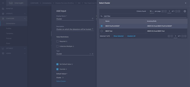
● Click Add
Step 17. Click Map.
Step 18. Click Map in the input field Host.
Step 19. Click Static Value and click the host on which the datastore will be hosted. If cluster is specified, then host will be ignored.
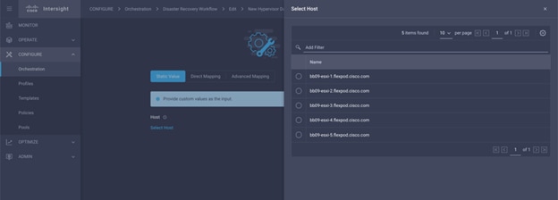
Step 20. Click Select and Map.
Step 21. Click Map in the input field Datastore.
Step 22. Click Direct Mapping and click Workflow Input.
Step 23. Click Input Name and Create Workflow Input.
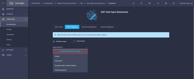
Step 24. In the Add Input wizard:
● Provide a Display Name and Reference Name (Optional)
● Click Required
● Click Set Default Value and Override
● Provide a default value for the datastore
● Click Add
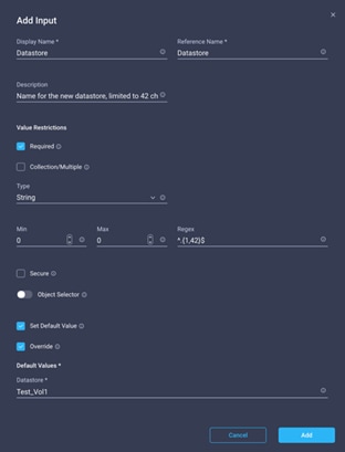
Step 25. Click Map.
Step 26. Click Map in the input field Type of Datastore.
Step 27. Click Direct Mapping and click Workflow Input.
Step 28. Click Input Name and Create Workflow Input.
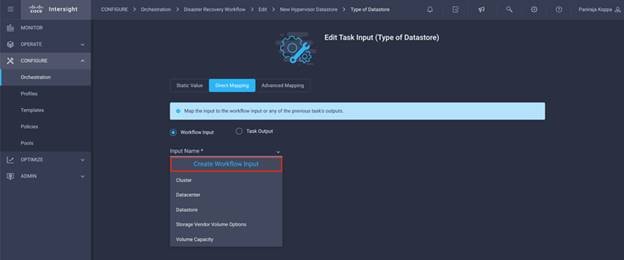
Step 29. In the Add Input wizard:
● Provide a Display Name and Reference Name (Optional)
● Click Required
● Make sure for Type, Types of Datastore is selected
● Click Set Default Value and Override
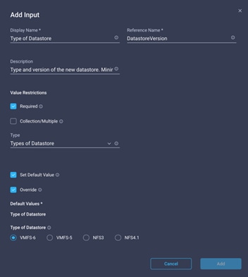
● Provide Remote Path. This is the remote path of the NFS mount point.
● Provide the hostnames or IP addresses of remote NFS server in NFS Server Address. NFS v4.1 this may have multiple entries.
● Click the Access Mode. Access mode for the NFS server. Click read-only if volume is exported as read-only.
● Click Add
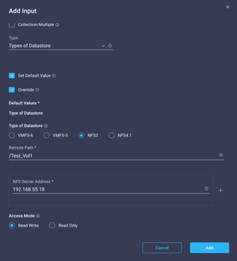
Step 30. Click Map.
Step 31. Click Save.
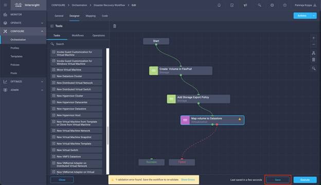
Note: This completes the task of creating datastore. All the tasks performed in on-premise FlexPod Datacenter are completed.
Procedure 10. Add a new Terraform Workspace
Step 1. Go to the Designer tab and click Tasks from Tools section.
Step 2. Drag and drop Terraform Cloud > Add Terraform Workspace task from the Tools section in the Design area.
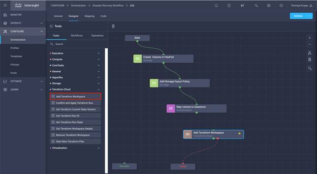
Step 3. Use Connector and connect between tasks Map volume to Datastore and Add Terraform Workspace and click Save.
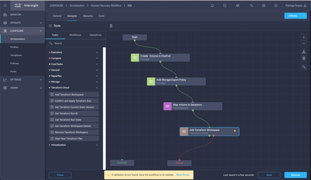
Step 4. Click Add Terraform Workspace. In the Task Properties area, click the General tab. Optionally, you can change the Name and Description for this task.
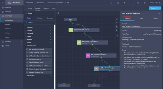
Step 5. In the Task Properties area, click Inputs.
Step 6. Click Map in the input field Terraform Cloud Target.
Step 7. Click Static Value and click Select Terraform Cloud Target. Select the Terraform Cloud for Business Account which was added as explained in section Configure Cisco Intersight Service for HashiCorp Terraform.
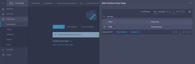
Step 8. Click Map.
Step 9. Click Map in the input field Terraform Organization Name.
Step 10. Click Static Value and click Select Terraform Organization. Select the name of the Terraform Organization that you are part of in Terraform Cloud for Business account.
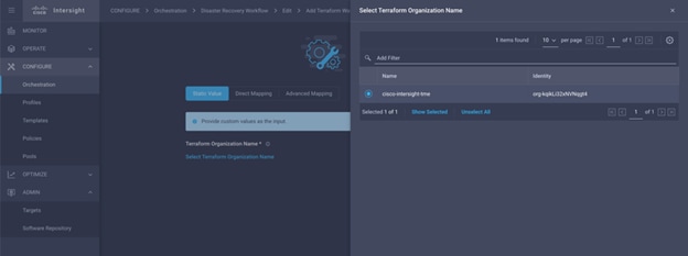
Step 11. Click Map.
Step 12. Click Map in the input field Terraform Workspace Name. This will be the new workspace we create in the Terraform Cloud for Business Account.
Step 13. Click Direct Mapping and click Workflow Input.
Step 14. Click Input Name and Create Workflow Input.
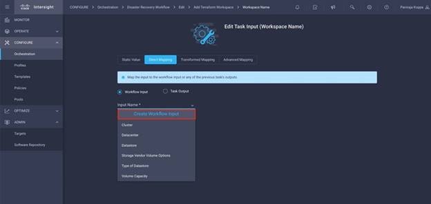
Step 15. In the Add Input wizard:
● Provide a Display Name and Reference Name (Optional)
● Click Required
● Make sure for Type, String is selected
● Click Set Default Value and Override
● Provide a default name for workspace
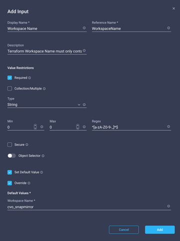
● Click Add
Step 16. Click Map.
Step 17. Click Map in the input field Workspace Description.
Step 18. Click Direct Mapping and click Workflow Input.
Step 19. Click Input Name and Create Workflow Input.
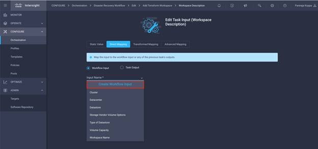
Step 20. In the Add Input wizard:
● Provide a Display Name and Reference Name (Optional)
● Make sure for Type, String is selected
● Click Set Default Value and Override
● Provide workspace description
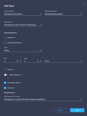
● Click Add
Step 21. Click Map.
Step 22. Click Map in the input field Execution Mode.
Step 23. Click Static Value, click Execution Mode, and then click remote.
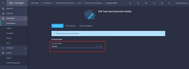
Step 24. Click Map.
Step 25. Click Map in the input field Apply Method.
Step 26. Click Static Value and click Apply Method. Click Manual Apply.
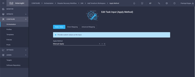
Step 27. Click Map.
Step 28. Click Map in the input field User Interface.
Step 29. Click Static Value and click User Interface. Click Console UI.
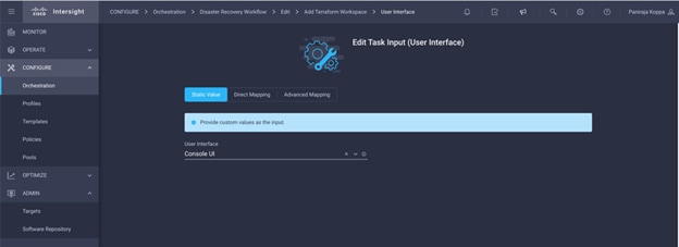
Step 30. Click Map.
Step 31. Click Map in the input field and select your workflow.
Step 32. Click Static Value. Click Choose your workflow. Click Version control workflow.
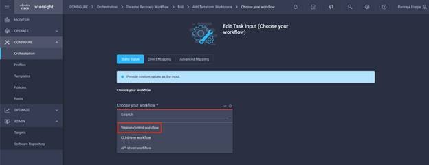
Step 33. Provide the GitHub repository details:
● In Repository Name, enter the name of repository detailed in section Set up environment prerequisites.
● Provide OAuth Token ID as detailed in section Setting up environment prerequisites
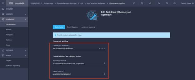
Step 34. Click Map.
Step 35. Click Save.
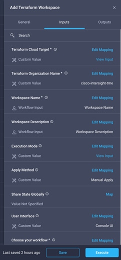
Note: This completes the task of creating a workspace in Terraform Cloud for Business account.
Procedure 11. Add non-sensitive variables to workspace
Step 1. Go to the Designer tab and click Workflows from Tools section.
Step 2. Drag and drop "Terraform > Add Terraform Variables" workflow from the Tools section in the Design area.
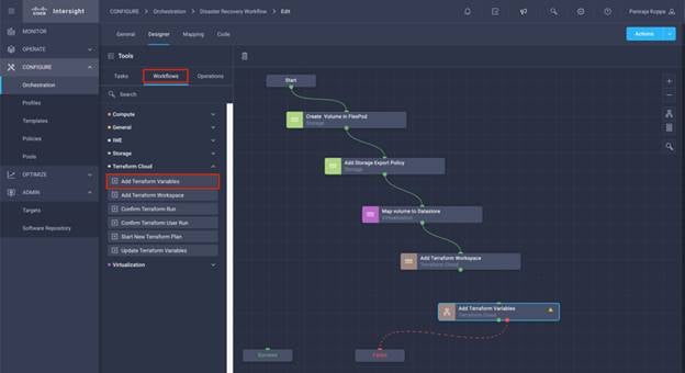
Step 3. Use Connector and connect between tasks Add Terraform Workspace and Add Terraform Variables and click Save.
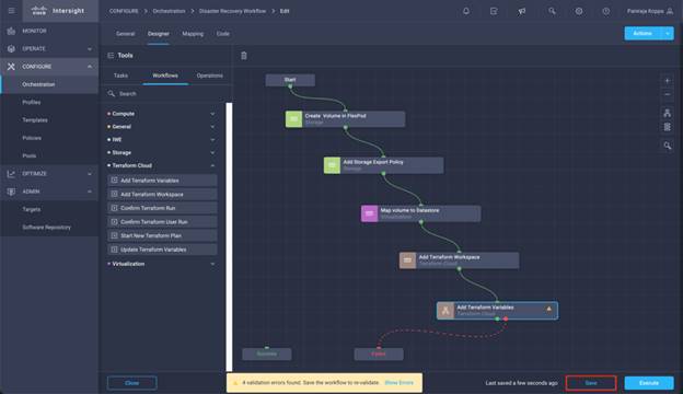
Step 4. Click Add Terraform Variables. In the Workflow Properties area, click the General tab. Optionally, you can change the Name and Description for this task.
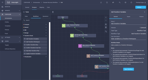
Step 5. In the Workflow Properties area, click Inputs.
Step 6. Click Map in the input field Terraform Cloud Target.
Step 7. Click Static Value and click Select Terraform Cloud Target. Select the Terraform Cloud for Business Account which was added as explained in section Configure Cisco Intersight Service for HashiCorp Terraform.
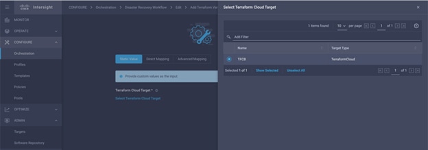
Step 8. Click Map.
Step 9. Click Map in the input field Terraform Organization Name.
Step 10. Click Static Value and click Select Terraform Organization. Select the name of the Terraform Organization that you are part of in Terraform Cloud for Business account.
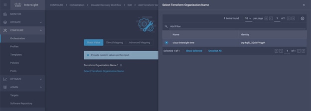
Step 11. Click Map.
Step 12. Click Map in the input field Terraform Workspace Name.
Step 13. Click Direct Mapping and click Task Output.
Step 14. Click Task Name and click Add Terraform Workspace.
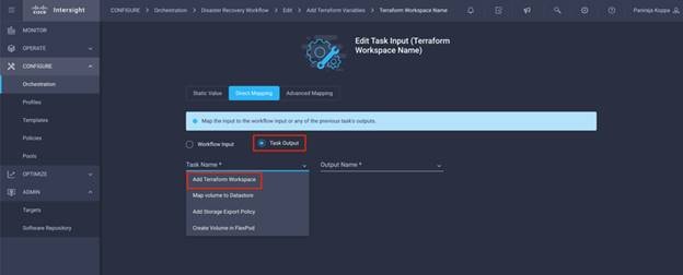
Step 15. Click Output Name and click Workspace Name.
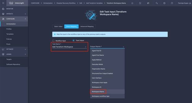
Step 16. Click Map.
Step 17. Click Map in the input field Add Variables Options.
Step 18. Click Direct Mapping and click Workflow Input.
Step 19. Click Input Name and Create Workflow Input
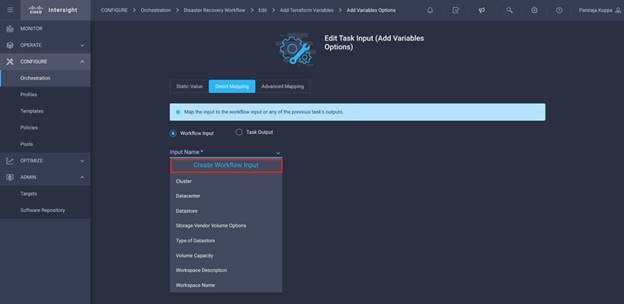
Step 20. In the Add Input wizard:
● Provide a Display Name and Reference Name (Optional)
● Make sure for Type, String is selected
● Click Set Default Value and Override
● Click Variable Type and click Non Sensitive Variables
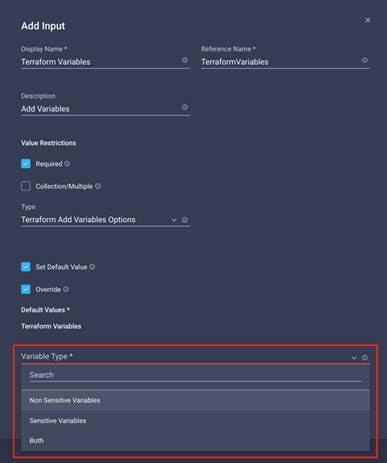
Step 21. In the Add Terraform Variables section, provide the following:
● Key: name_of_on-prem-ontap
● Value: Provide the name of On-premise ONTAP added in section Deploying FlexPod Datacenter
● Description: Name of the On-premise ONTAP
Step 22. Click + to add additional variables.
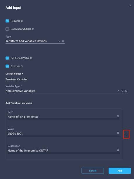
Step 23. Add all the Terraform Variables as shown in Table 15. You can also provide a default value.
Table 15. Terraform Variables and Descriptions
| Terraform Variable Name |
Description |
| name_of_on-prem-ontap |
Name of the On-premise ONTAP (FlexPod) |
| on-prem-ontap_cluster_ip |
The ip address of the storage cluster management interface |
| on-prem-ontap_user_name |
Admin username for the storage cluster |
| region |
AWS region where the working environment will be created |
| Subnet |
AWS subnet id where the working environment will be created |
| vpc_id |
The VPC ID where the working environment will be created |
| license_type |
The type of license to use |
| source_volume |
The name of the source volume |
| source_storage_vm_name |
The name of the source SVM |
| destination_volume |
Name of volume on CVO |
| schedule_of_replication |
The default is 1hour |
| name_of_volume_to_create_on_cvo |
Name of the cloud volume |
| name_of_cvo_cluster |
The name of the Cloud Volumes ONTAP working environment |
Step 24. Click Add.
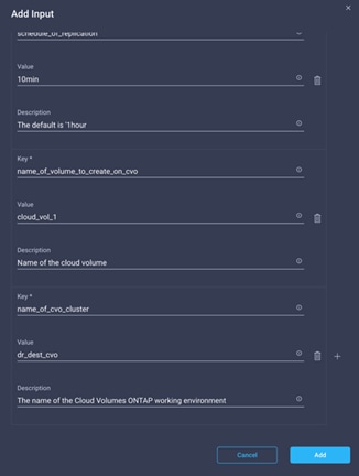
Step 25. Click Map.
Step 26. Click Save.
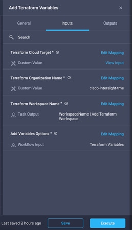
Note: This completes the task of adding the required Terraform variables to workspace. Next, add the required sensitive Terraform variables to the workspace. You can also combine both into a single task.
Procedure 12. Add sensitive variables to a workspace
Step 1. Go to the Designer tab and click Workflows from Tools section.
Step 2. Drag and drop Terraform > Add Terraform Variables workflow from the Tools section on the Design area.
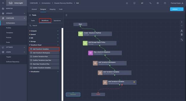
Step 3. Use Connector and connect between two Add Terraform Workspace tasks and click Save.
Note: A warning displays stating 2 tasks have the same name. Ignore the error for now since you will change the task name in next step.
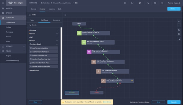
Step 4. Click Add Terraform Variables. In the Workflow Properties area, click the General tab. Change the Name to Add Terraform Sensitive Variables.
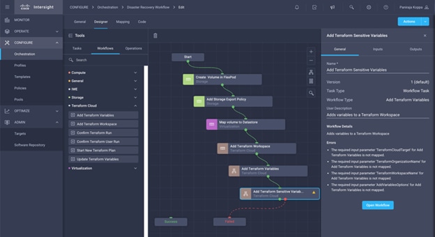
Step 5. In the Workflow Properties area, click Inputs.
Step 6. Click Map in the input field Terraform Cloud Target.
Step 7. Click Static Value and click Select Terraform Cloud Target. Select the Terraform Cloud for Business Account, which was added, as explained in section Configure Cisco Intersight Service for HashiCorp Terraform.
Step 8. Click Map.
Step 9. Click Map in the input field Terraform Organization Name.
Step 10. Click Static Value and click Select Terraform Organization. Select the name of the Terraform Organization that you are part of in Terraform Cloud for Business account.
Step 11. Click Map.
Step 12. Click Map in the input field Terraform Workspace Name.
Step 13. Click Direct Mapping and click Task Output.
Step 14. Click Task Name and click Add Terraform Workspace.
Step 15. Click Output Name and click the output Workspace Name.
Step 16. Click Map.
Step 17. Click Map in the input field Add Variables Options.
Step 18. Click Direct Mapping and click Workflow Input.
Step 19. Click Input Name and Create Workflow Input.
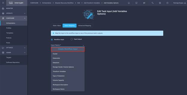
Step 20. In the Add Input wizard:
● Provide a Display Name and Reference Name (Optional)
● Make sure for Type, Terraform Add Variables Options is selected
● Click Set Default Value
● Click Variable Type and click Sensitive Variables
● Click Add
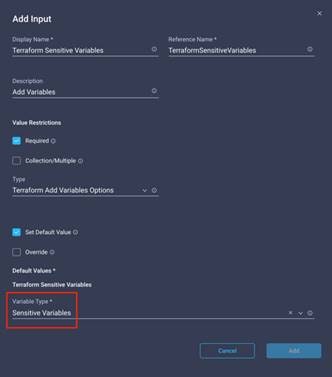
Step 21. In the Add Terraform Variables section, provide the following:
● Key: cloudmanager_refresh_token
● Value: Input the refresh token for NetApp Cloud Manager API operations.
● Description: Refresh token.
Note: For more information about obtaining a refresh token for the NetApp Cloud Manager API operations, refer to section Set up environment prerequisites.
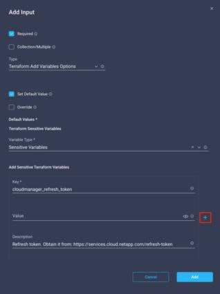
Step 22. Add all the Terraform Sensitive Variables as shown in Table 16. You can also provide a default value.
Table 16. Terraform Sensitive Variables and Descriptions
| Terraform Sensitive Variable Name |
Description |
| cloudmanager_refresh_token |
Refresh token. Obtain it from: https://services.cloud.netapp.com/refresh-token |
| connector_id |
The client ID of the Cloud Manager Connector. Obtain it from https://cloudmanager.netapp.com |
| cvo_admin_password |
The admin password for Cloud Volumes ONTAP |
| on-prem-ontap_user_password |
Admin password for the storage cluster |
Step 23. Click Add.
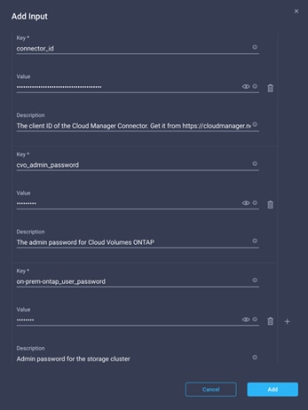
Step 24. Click Map.
Note: This completes the task of adding the required Terraform sensitive variables to workspace. Next, you will start a new Terraform plan in the configured workspace.
Procedure 13. Start a new Terraform Plan
Step 1. Go to the Designer tab and click Tasks from the Tools section.
Step 2. Drag and drop "Terraform Cloud > Start New Terraform Plan" task from the Tools section on the Design area.
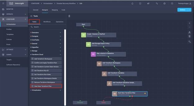
Step 3. Use connector and connect between tasks Add Terraform Sensitive Variables and Start New Terraform Plan tasks and click Save.
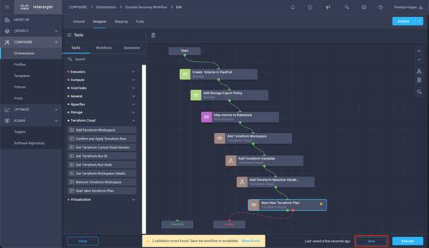
Step 4. Click Start New Terraform Plan. In the Task Properties area, click the General tab. Optionally, you can change the Name and Description for this task.
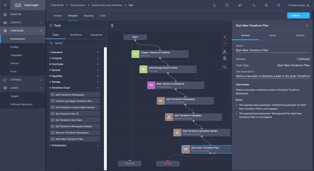
Step 5. In the Task Properties area, click Inputs.
Step 6. Click Map in the input field Terraform Cloud Target.
Step 7. Click Static Value and click Select Terraform Cloud Target. Select the Terraform Cloud for Business Account which was added as explained in section Configuring Cisco Intersight Service for HashiCorp Terraform of the document.
Step 8. Click Map.
Step 9. Click Map in the input field Workspace ID.
Step 10. Click Direct Mapping and click Task Output.
Step 11. Click Task Name and click Add Terraform Workspace.
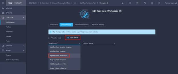
Step 12. Click Output Name and click Workspace ID.
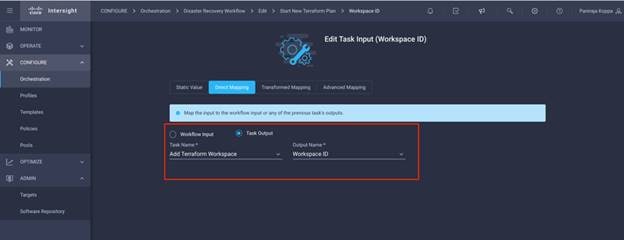
Step 13. Click Map.
Step 14. Click Map in the input field Reason for starting plan.
Step 15. Click Direct Mapping and click Workflow Input.
Step 16. Click Input Name and Create Workflow Input.
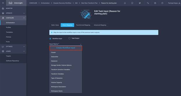
Step 17. In the Add Input wizard:
● Provide a Display Name and Reference Name (Optional)
● Make sure for Type, String is selected
● Click Set Default Value and Override
● Input a default value for Reason for starting plan
● Click Add
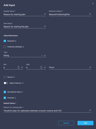
Step 18. Click Map.
Step 19. Click Map in the input field Plan Operation.
Step 20. Click Static Value and click Plan Operation. Click new plan.
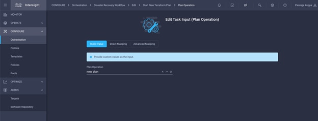
Step 21. Click Map.
Step 22. Click Save.
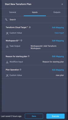
Note: This completes the task of adding a Terraform Plan in Terraform Cloud for Business account. Next, you will create a sleep task for few seconds.
Procedure 14. Sleep Task for Synchronization
Note: Terraform Apply requires RunID which is generated as part of the Terraform Plan task. Waiting a few seconds between the Terraform Plan and Terraform Apply actions will avoid timing issues.
Step 1. Go to the Designer tab and click Tasks from the Tools section.
Step 2. Drag and drop "Core Tasks > Sleep Task" from the Tools section in the Design area.
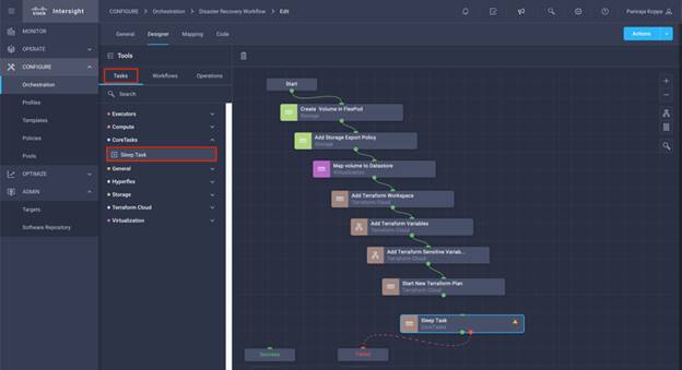
Step 3. Use Connector and connect between tasks Start New Terraform Plan and Sleep Task and click Save.
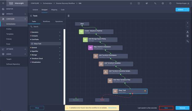
Step 4. Click Sleep Task. In the Task Properties area, click the General tab. Optionally, you can change the Name and Description for this task. In this example, the name of the task is Synchronize.
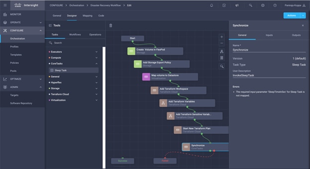
Step 5. In the Task Properties area, click Inputs.
Step 6. Click Map in the input field Sleep Time in Seconds.
Step 7. Click Static Value and input 15 in Sleep Time in Seconds.
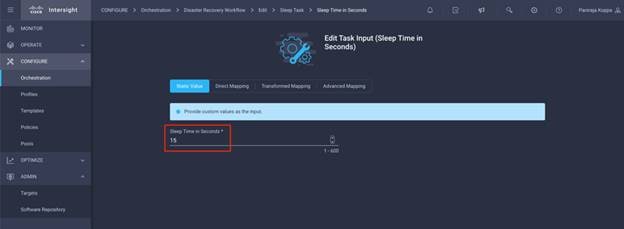
Step 8. Click Map.
Step 9. Click Save.
Note: This completes the sleep task. Next, you will create the last task of this workflow, confirming and applying the Terraform Run.
Procedure 15. Confirm and apply Terraform Run
Step 1. Go to the Designer tab and click Tasks from the Tools section.
Step 2. Drag and drop Terraform Cloud > Confirm and Apply Terraform Run task from the Tools section in the Design area.
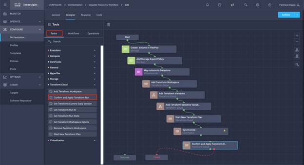
Step 3. Use connector and connect between tasks Synchronize and Confirm and Apply Terraform Run tasks and click Save.
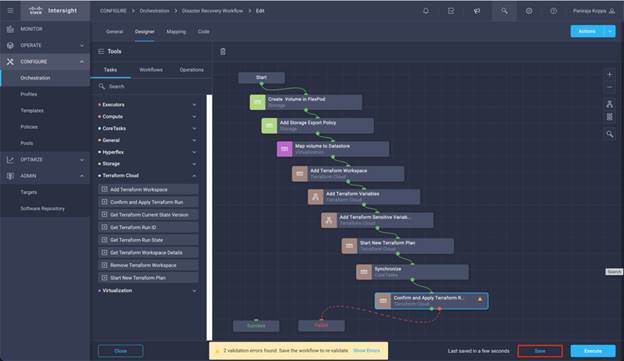
Step 4. Click Confirm and Apply Terraform Run. In the Task Properties area, click the General tab. Optionally, you can change the Name and Description for this task.
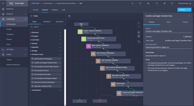
Step 5. In the Task Properties area, click Inputs.
Step 6. Click Map in the input field Terraform Cloud Target.
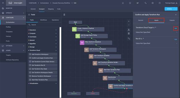
Step 7. Click Static Value and click Select Terraform Cloud Target. Select the Terraform Cloud for Business Account which was added as explained in section Configure Cisco Intersight Service for HashiCorp Terraform.

Step 8. Click Map.
Step 9. Click Map in the input field Run ID.
Step 10. Click Direct Mapping and click Task Output.
Step 11. Click Task Name and click Start New Terraform Plan.
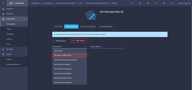
Step 12. Click Output Name and click Run ID.
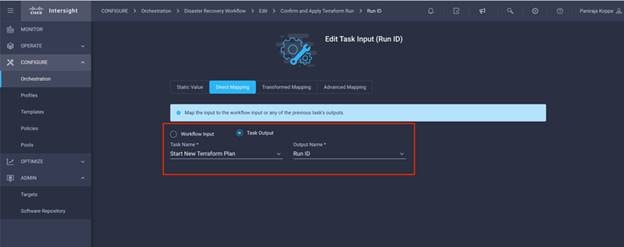
Step 13. Click Map.
Step 14. Click Save.
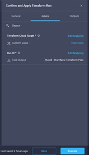
Note: This completes the Confirm and Apply Terraform Run task. Use Connector and connect between the Confirm and Apply Terraform Run task and the Success and Failed tasks.
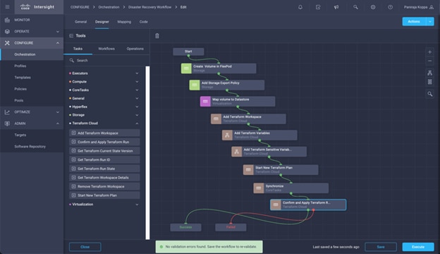
Step 15. Click Auto Align Workflow so that all tasks are aligned. Click Save.
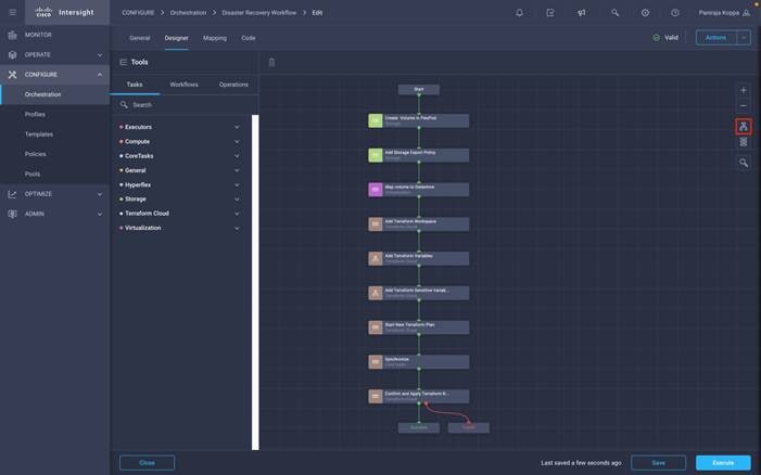
Procedure 16. Import a Cisco built workflow
Cisco Intersight Cloud Orchestrator enables you to export workflows from a Cisco Intersight account to your system and then import them to another account. A JSON file was created by exporting the built workflow which can be imported to your account
JSON file for the workflow component is available in the GitHub repository: https://github.com/ucs-compute-solutions/FlexPod_DR_Workflows
Step 1. Click Orchestration from the left navigation pane.
Step 2. Click Import.
The Import wizard appears.
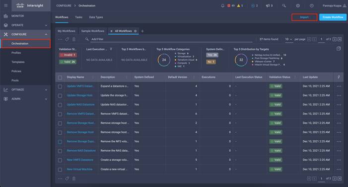
Step 3. In the Select File screen:
● From the Organization drop-down list, click the organization to which you want to import the workflow(s).
● Click Browse and select the JSON file that contains the Workflow(s).
Note: Ensure that the file size of the JSON file is not more than 1MB. If the file size is more than 1MB, export the workflow(s) in batches, and then try import.
● Click Next.
Cisco Intersight Cloud Orchestrator validates the JSON file and displays the workflow(s) in the Details screen.
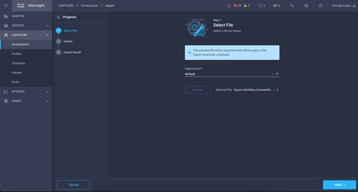
Step 4. In the Details screen:
● To associate an additional tag to the components listed in the table, enter the tag in the Set Tags field.
Note: Set Tags is an optional field. You must enter the tag in the key:value format.
● If one or more workflow components are already available in the system, click a rule to replace or skip the duplicate components.
Note: A warning displays. This happens because the System-defined objects cannot be imported and will be skipped.
● Click Import.
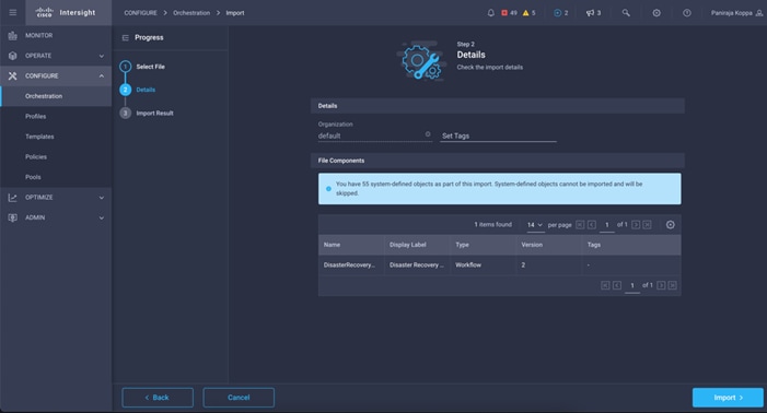
Step 5. In the Import Result screen:
● Verify the status of the imported workflow.
● To view the details of the import request:
◦ Click the link displayed above the table.
◦ Alternatively, click the Requests icon displayed in the menu bar.
◦ Click Close.
Note: You can run the imported workflow from the Workflows tab.
Step 6. Click the newly imported workflow. Multiple errors are displayed.
These errors are shown because the original workflow had multiple workflow inputs which were mapped to static values. For example, in Disaster Recovery Workflow, task Create Volume in FlexPod has a task input Storage Device, Storage Vendor Aggregate having static values mapped. These static values will not be carried to the account where it is imported.
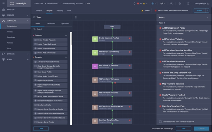
Step 7. Click the first task.
Step 8. In the Workflow Properties area, click Inputs.
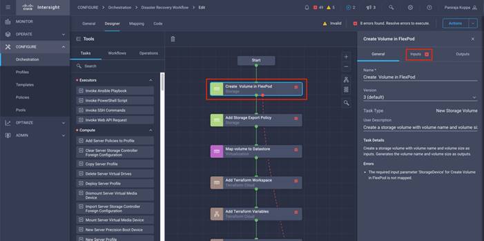
Step 9. For the task input which shows Value Not Specified, click Map.
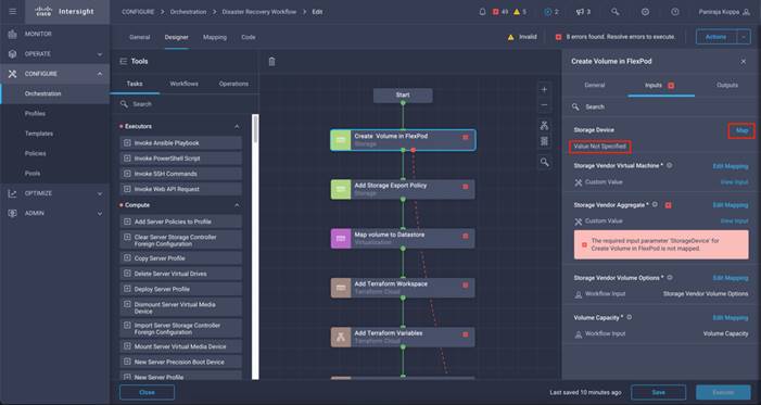
Step 10. Provide the new value on the current Intersight account and click Map.
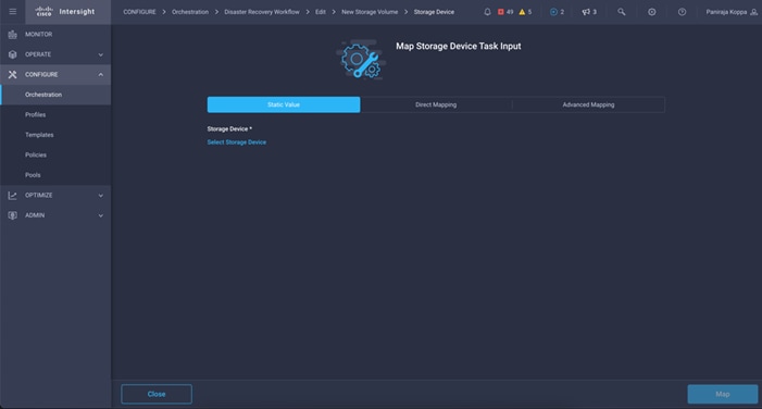
Step 11. Repeat steps 1 - 10 for all inputs.
Step 12. For the task input that shows an error, click Edit Mapping.
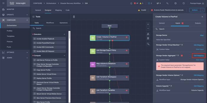
Step 13. Provide the new value on the current Cisco Intersight account and click Map.
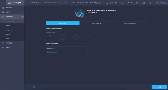
Step 14. Repeat steps 1 – 13 for all inputs.
Step 15. Repeat providing new values to the workflow input for all the tasks and click Save.
Step 16. Make sure the workflow displays as Valid.
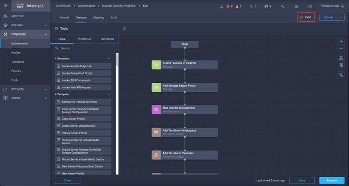
Step 17. Once Valid, you can execute the imported workflow from the Workflows tab.
Procedure 17. Export a Workflow
Complete this procedure if you have a requirement to export a workflow from one Cisco Intersight account to another.
Step 1. Click Orchestration from the left navigation pane.
Step 2. Click the Workflow tab.
Step 3. From the tabular list of workflows, do one of the following:
● Click a workflow then click the Ellipsis (…) icon in the same row and then click Export Workflow.
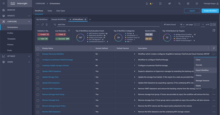
● Select multiple workflows, click the Ellipsis (…) icon from the header or footer of the tabular list and then click Export Workflow.
Step 4. Click the workflow. Navigate to Actions > Export Workflow.
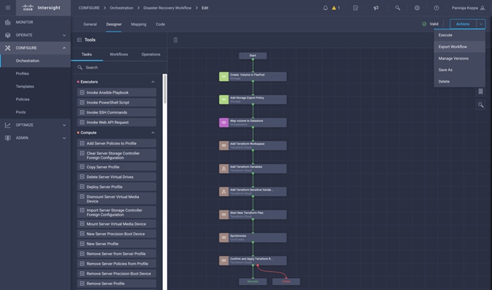
Note: You can also export workflows from the Actions menu in the Workflow Designer window.
Step 5. In the Export Workflow screen:
● In the JSON File Name field, use the default filename or enter a filename of your choice for the JSON file that stores the workflow components.
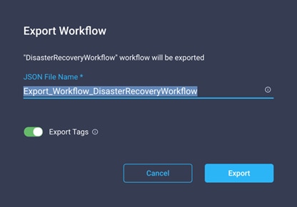
● Use the Export Tags toggle button to include or exclude the user-defined tags. ICO does not export the system-defined tags.
● Click Export.
Step 6. Save a local copy of the JSON file.
Procedure 18. Execute a Workflow
Step 1. To execute a workflow, select workflow from the tabular list of workflows and click Execute.
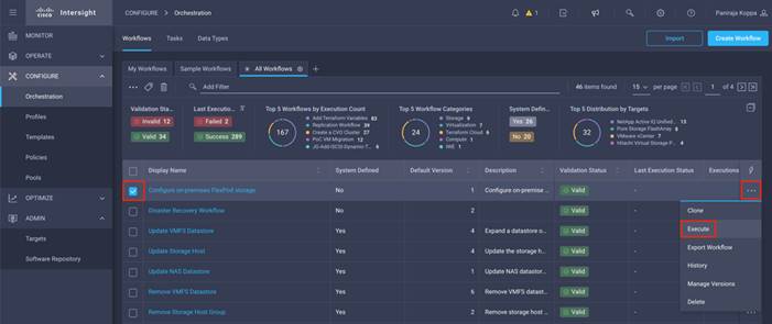
Step 2. Alternatively, you can click the workflow name and then click Execute in the Workflow Designer.
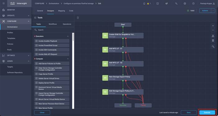
Note: You must have all the required privileges to execute all the domain tasks within a workflow. For example, you can successfully execute a workflow that includes storage and virtualization tasks only if you have both Storage and Virtualization Administrator privileges. In the absence of either one of these privileges, the Execute button will not be displayed and the user cannot execute the workflow.
Step 3. Select the organization where the workflow was created and select the Workflow Instance Name.
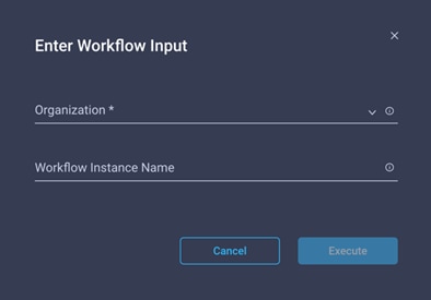
Note: When the organization is selected, it lists all the input variables along with the default values entered which can be changed. The screenshot show below is for all workflow input configured for Disaster Recovery Workflow.
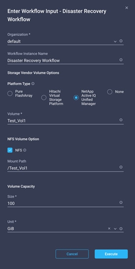
Step 4. After entering values for all input variables, click Execute to run the workflow.
You can observe the progress of each task, input each task took, output it produced and so on, while the execution is happening.
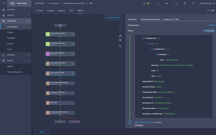
When all the tasks are complete, you can see the status as Success.
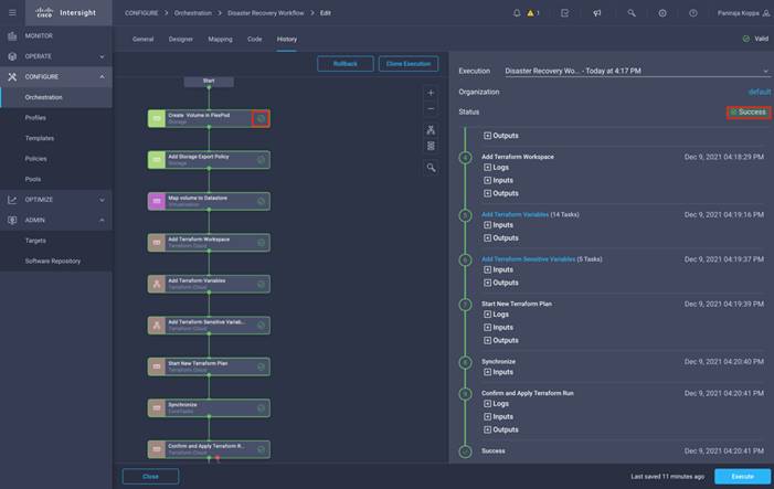
In the previous section, 2 workflows were created: Configure on-premises FlexPod storage and Disaster Recovery Workflow. Configure on-premises FlexPod storage workflow will be executed first since it creates and configures the Storage Virtual Machine which can be used by Disaster Recovery Workflow.
After the Configure on-premises FlexPod storage workflow execution is complete, you can verify it in the ONTAP System manager that a new Storage VM is created with NFS as configured protocol.
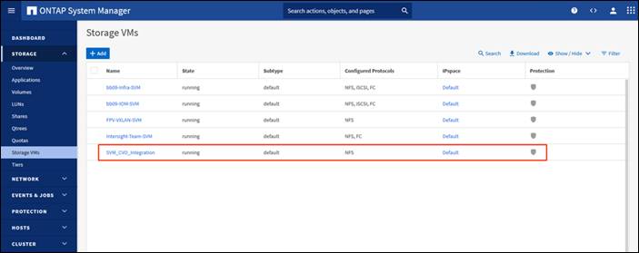
2 NFS interfaces are created, one logical interface mapped to each controller:
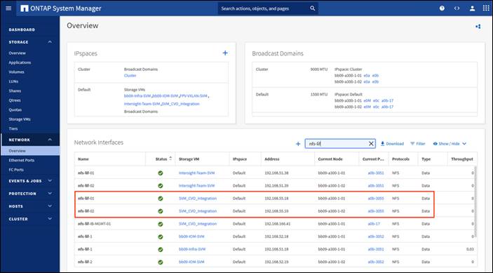
NFS is the configured access protocol for all the volumes created in this Storage Virtual Machine:
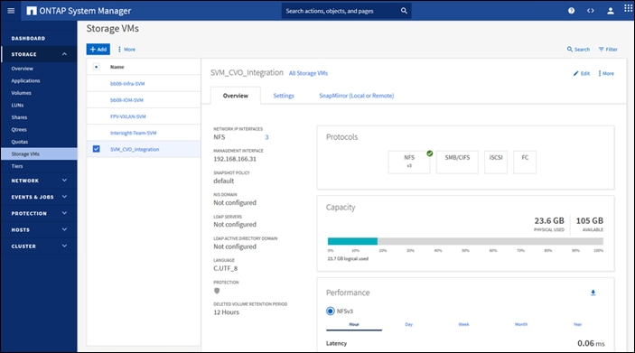
A storage export policy is created in Storage Virtual Machine name which can be added to volumes later:
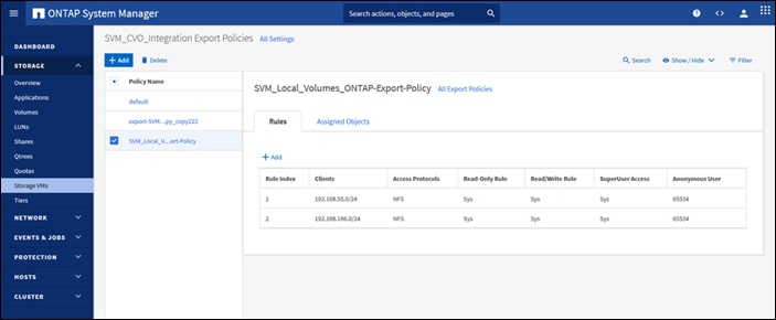
After the Disaster Recovery Workflow execution is complete, you can verify that a new volume is created in the FlexPod storage:
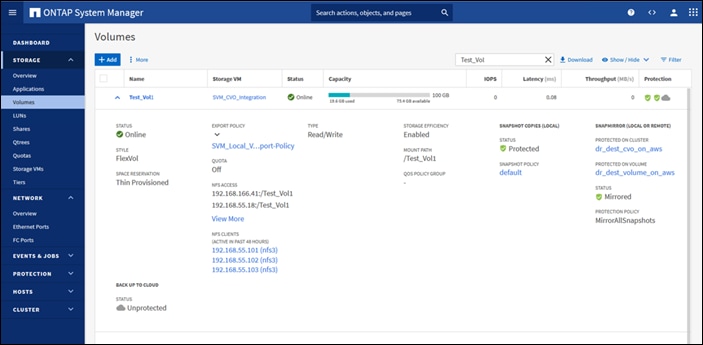
The created volume is mounted as datastore in the Vcenter:
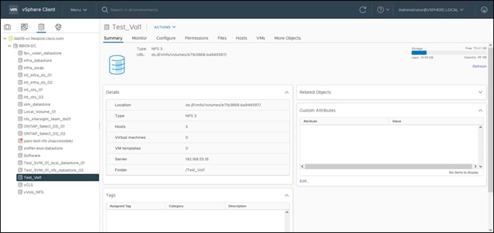
In the Terraform cloud a new workspace is created:
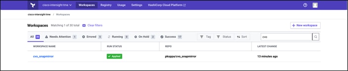
The workspace has been configured with all non-sensitive and sensitive variables:
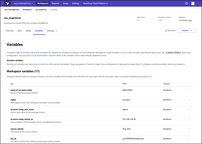
The execution was triggered in the Terraform cloud and it completed successfully:
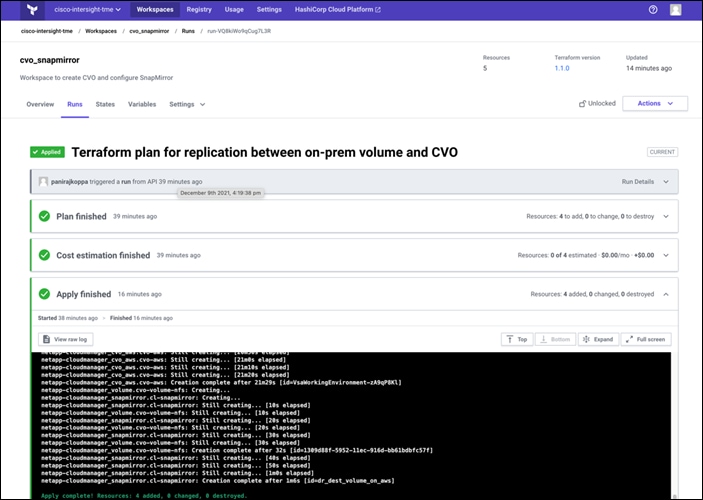
Terraform cloud lists all the resource created:
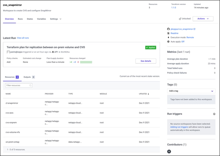
In the NetApp Cloud Manager, you can see that the on-premise FlexPod storage was added into the working environment as well a newly created Cloud Volumes ONTAP cluster:
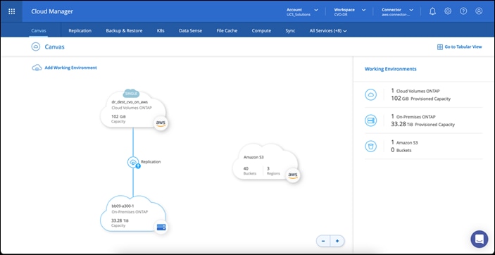
In the Cloud Volumes ONTAP cluster, you can see the created volumes:
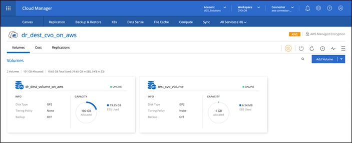
You can also verify that the SnapMirror relationship is established between the on-premises volume and the cloud volume:
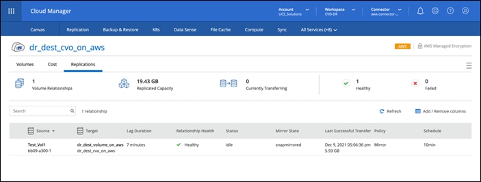
More information on the replication task can be found in Replication tab:
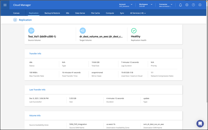
Procedure 19. Rollback execution
Rollback Execution helps in reverting the entities created or modified when executing a workflow. Rollback occurs at the task level and can be executed for selected tasks in a workflow. Rollback can be executed for workflows containing tasks for which rollback is defined. For example, if a workflow has two tasks and if the two tasks have defined what a rollback is, then the Rollback button is displayed.
If a workflow contains a series of tasks, the rollback occurs for each task in the workflow. When a rollback is triggered, all tasks in workflow are collected and the status is displayed. When executing rollback tasks in a series, you can toggle ON the Abort rollback, if rollback for a task fails, to stop rollback execution if the rollback for a task in the series fails.
Step 1. Do one of the following:
● Workflow Designer—Click Rollback in the bottom of the window.
● Requests page—Select a request and click Rollback in the Actions column.
● Detailed Request page—In the Requests page, click the specific request to navigate to the detailed request page and click Rollback.
Step 2. Click Rollback. The Rollback Wizard appears displaying the list of all applicable tasks that can be rollback are displayed. This wizard displays the requests which in turn list the executed workflow details.
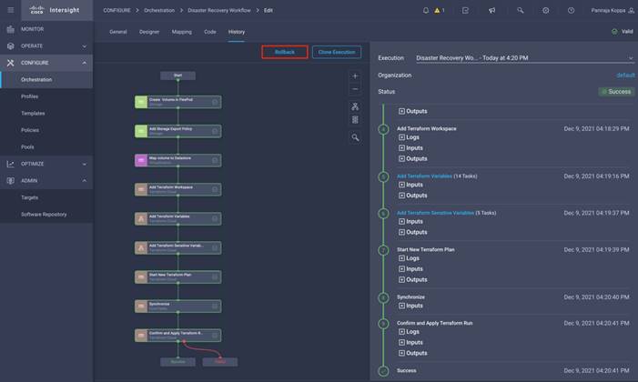
Step 3. Select the specific tasks or all tasks to initiate a rollback action. On successful completion, a separate workflow is initiated with prefix “RollbackWorkflow,” task status is either Failed or Completed and the completed task can no longer selected.
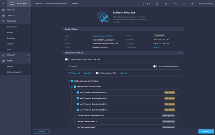
Procedure 20. Manage Versions
It is possible to create a new version of your workflow with new set of tasks added or deleted. You can manage different versions of workflow; each version consisting of different set of inputs, tasks and so on. You can create a new workflow version, delete an existing version, and change the default version.
Step 1. Click the workflow.
Step 2. Click Actions > Manage Versions.
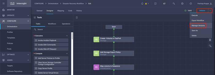
Step 3. Click Create a New Version.
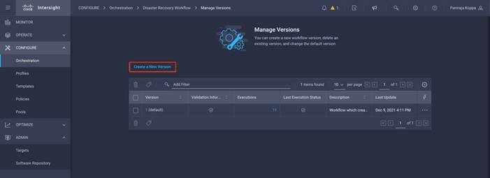
Step 4. Select the source version. Provide a new version number and click Set as Default Version if you want this version to be displayed by default. Click Create.
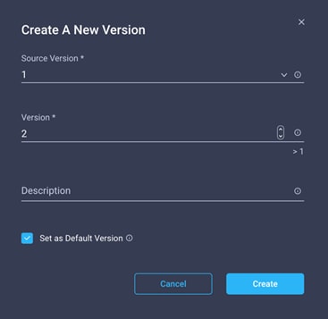
Step 5. Click the new version.
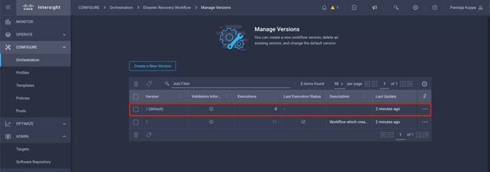
Note: You can make the necessary modification in Manager Versions. The changes will only be reflected in version 2. The version 1 will not have the changes.
Solution Validation - Test Methodology and Success Criteria
In this section, let’s revisit the solution with a sample data replication workflow and take a few measures to verify the integrity of the data replication from the NetApp ONTAP instance running in FlexPod to NetApp Cloud Volumes ONTAP running in AWS.
You’ve used the Cisco Intersight workflow orchestrator in this solution and will continue to leverage this for our use-case.
It should be noted that only a limited set of Cisco Intersight workflows have been used in this solution, that does not by anyway represent the entire set of workflows that Cisco Intersight is equipped with. You can create custom workflows based on their specific requirements and have them triggered from Cisco Intersight; the options are endless.
To perform the validation of a successful DR scenario, you will move the data from a volume in ONTAP that is part of the FlexPod to CVO using SnapMirror and will try to access the data from an EC2 instance followed by a data integrity check.
The following are the high-level steps to verify the success criteria of this solution:
● Generate a SHA256 checksum on the sample dataset that is present in an ONTAP volume in FlexPod
● Setup a volume SnapMirror between ONTAP in FlexPod and CVO in AWS
● Replicate the sample dataset from FlexPod to CVO
● Break the SnapMirror relationship and promote the volume in CVO to production
● Map the CVO volume with the dataset to an EC2 instance in AWS
● Generate a SHA256 checksum on the sample dataset in CVO
● Compare the checksum on source and destination, it is expected that the checksums at both sides match.
Procedure 1. Validate the solution
Step 1. Create a workflow in Intersight to create and export a volume in FlexPod.
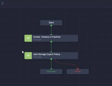
Step 2. Provide the required inputs and execute the workflow.
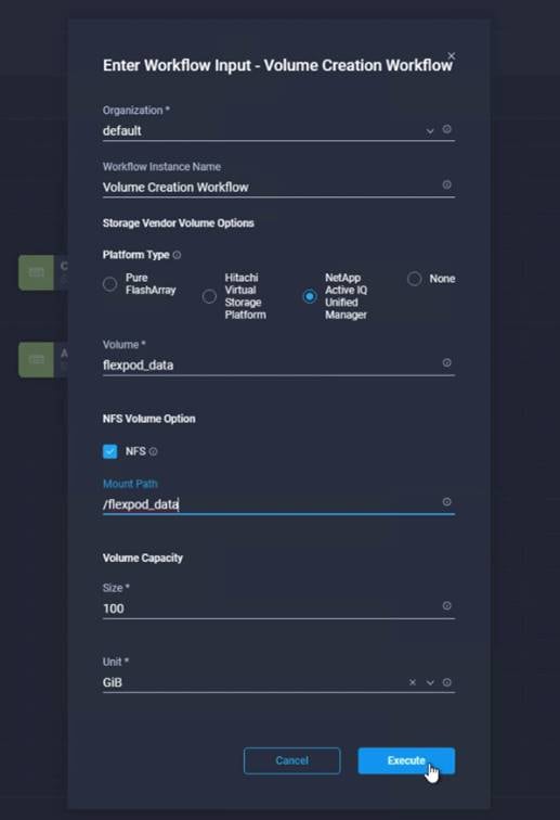
Step 3. Verify the newly created volume in the system manager. The volume status will be unprotected since a SnapMirror relationship is yet to be established.
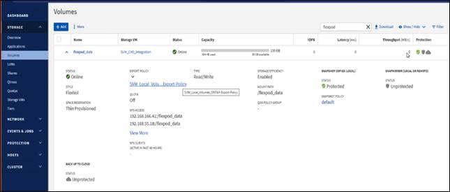
Step 4. Mount the same NFS volume to an on-premises virtual machine, then copy the sample dataset and perform the checksum.
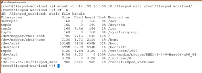
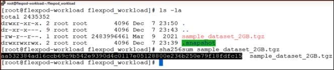
Step 5. Create and execute another Cisco Intersight workflow to setup a SnapMirror relationship between this volume in FlexPod and CVO.
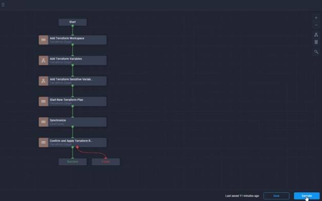
Step 6. When the workflow is executed successfully, you can view the replication status in Cloud Manager.
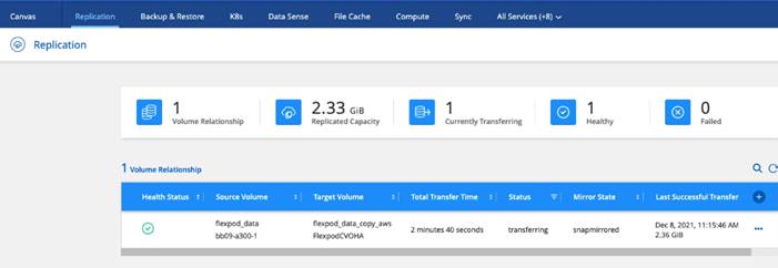
Step 7. Wait for the data transfer to complete.
Step 8. When the data transfer is complete, simulate a disaster on the source side by stopping the SVM that hosts the flexpod_data volume.
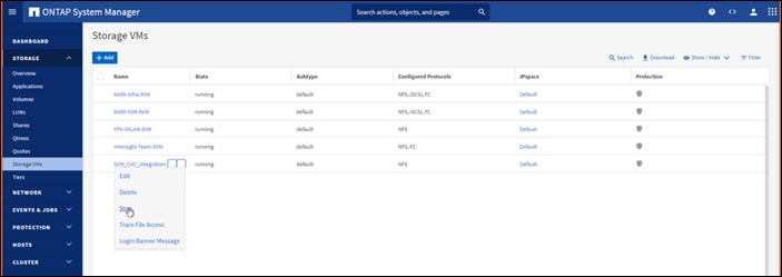
After the SVM has been stopped, the flexpod_data volume will not be visible in the Cloud Manager:
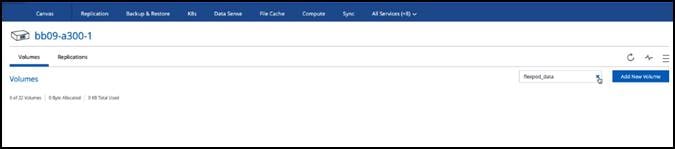
Step 9. Break the replication relationship and promote the CVO destination volume to production.
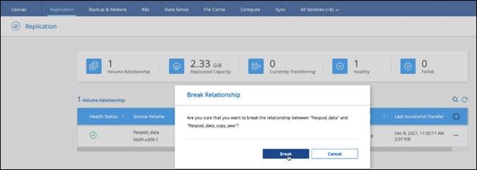
Step 10. Edit the volume and enable client access by associating it with an export policy.
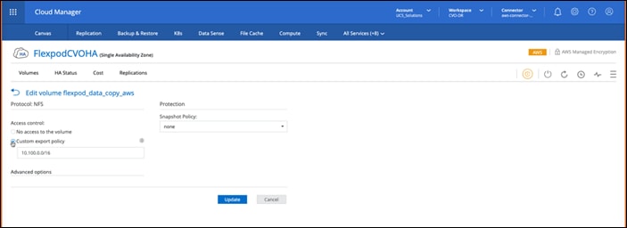
Step 11. Obtain the ready to use mount command for the volume.
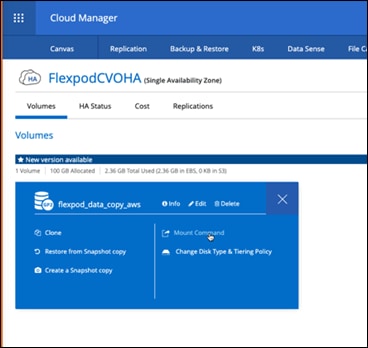
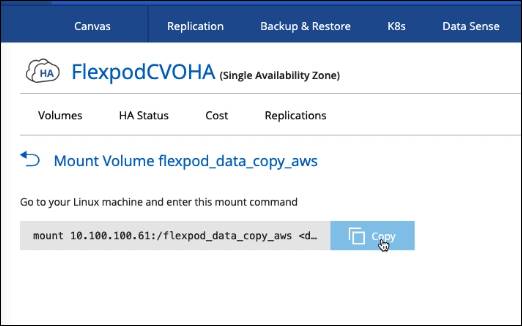
Step 12. Mount the volume to an EC2 instance, verify that the data is present in the destination volume and generate the SHA256 checksum of the sample_dataset_2GB file.
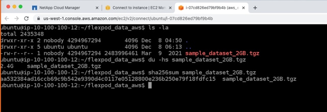
Step 13. Compare the checksum values at both source (FlexPod) and destination (CVO).
The checksums match as the source and destination.
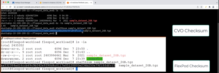
You can infer that the data replication from the source to the destination has been completed successfully and the data integrity has been maintained. This data can now be safely consumed by the applications to continue to the serve the clients while the source site goes through a restoration.
In this solution, the NetApp Cloud Data service, Cloud Volumes ONTAP, and the FlexPod Datacenter infrastructure were implemented to build a disaster recovery solution with the public cloud powered by the Cisco Intersight Cloud Orchestrator. The FlexPod datacenter solution has constantly evolved to equip its customers with the ability to continually modernize their applications and business delivery processes. With this solution, FlexPod you can build a BCDR plan with the public cloud as your go-to location for a transient or full-time DR plan while keeping the cost of the DR solution low.
The data replication between on-premises FlexPod and NetApp Cloud Volumes ONTAP was handled by the proven SnapMirror technology, but you can also select other NetApp data transfer/synchronization tools like Cloud Sync for their data mobility requirements. Security of the data in-flight is ensured by leveraging the inbuilt encryption technologies based on TLS/ AES.
Whether a temporary DR plan for an application or a full-time DR plan for a business, the portfolio of products used in this solution can meet both requirements at scale. Powered by Cisco Intersight Workflow Orchestrator, the same can be automated with pre-built workflows that not just eliminate the need to rebuild processes but also accelerate the implementation of a BCDR plan.
The solution enables managing FlexPod Datacenter on-premises and data replication across hybrid cloud very easy and convenient with automation and orchestration capability using Cisco Intersight Cloud Orchestrator.
This solution emphasizes on the automated deployment of the CVO infrastructure and the configuration of the replication relationship between on-premises FlexPod and the public cloud. This section explains deploying CVO in all modes of operation; Single Node, HA in Single Availability Zone, and HA in Multiple Availability Zones using NetApp Cloud Manager. There are a few additional network settings that are required to deploy CVO across multiple Availability zones, which are explained in this section.
Before deploying CVO instance let’s see how quickly we can add FlexPod storage to the working environment using NetApp Cloud Manager.
Procedure 1. Add FlexPod Storage to Cloud Manager
Step 1. From the Canvas page, click Add Working Environment then click On-Premises and type On-Premises ONTAP, then click Next.
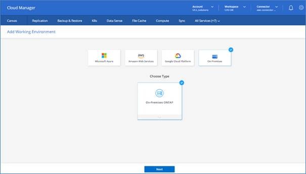
Step 2. Enter the Cluster management IP address and credentials, then click Add.
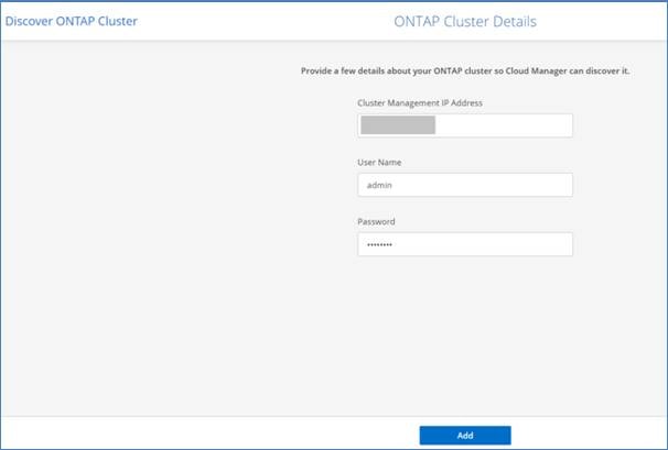
The On-Premises ONTAP cluster is discovered successfully.
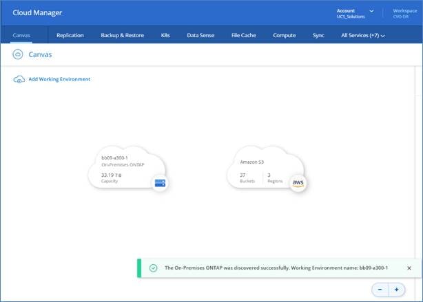
Now the replication service on the On-Premises ONTAP cluster should be disabled; it will be enabled after the Cloud Volume ONTAP is deployed and a replication relationship is setup with SnapMirror.
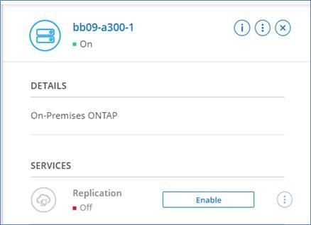
Procedure 2. Deploy CVO Single Node
Note: Cloud Manager automatically allocates the required number of private IP addresses to Cloud Volumes ONTAP. You need to ensure that your networking has enough private IP addresses available.
Step 1. From the Canvas page, click Add Working Environment.
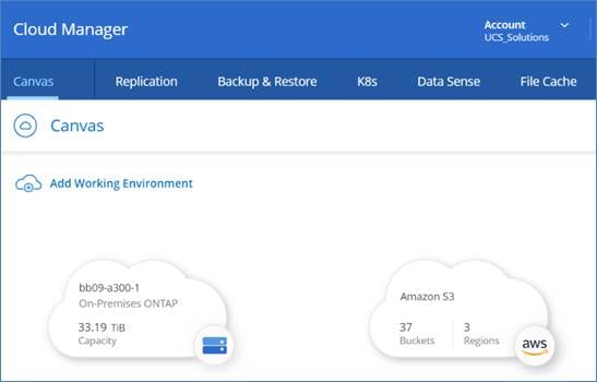
Step 2. Click Amazon Web Services, click Cloud Volume ONTAP Single Node, then click Next.
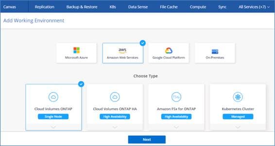
Step 3. Enter the Cluster name and credentials, add tags if needed then click Continue.
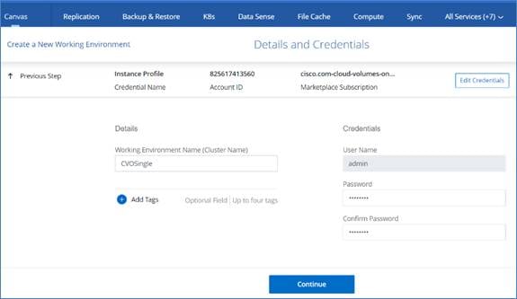
Step 4. Keep the services enabled or disable the individual services that you don’t want to use with Cloud Volumes ONTAP.
Step 5. Enter the network information that you recorded in the Network information sheet for Connector and CVO and select the SSH Authentication Method of your choice.
Note: If you need to use your own, refer to Security group rules.
Step 6. Click AWS Managed Encryption then click Continue.
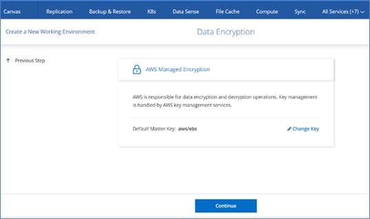
Step 7. On the Cloud Volumes ONTAP Charging Methods and NSS Account, specify which charging option you would like to use with this system, and then specify a NetApp Support Site account, then click Continue.
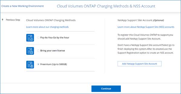
Note: The subnet should have internet connectivity through NAT device or proxy server.
Step 8. On the Preconfigured Packages page, select one of the packages to quickly launch Cloud Volumes ONTAP or click Change Configuration to select your own configuration.
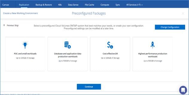
Step 9. On the Create Volume page, click Skip. You will create a volume at a later stage.
Step 10. Review the configuration and accept both options, then click Go.

The single node CVO deployment is initiated.
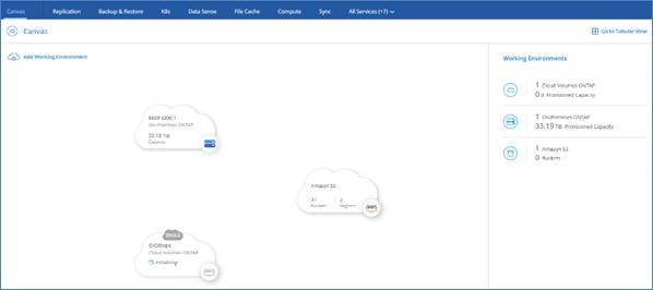
The CVO instance deployment progress can be tracked in the timeline from the All Services drop-down list.
Note: The single node CVO deployment could take about 25 minutes.
Procedure 3. Deploy CVO HA Pair Single AZ
Note: Cloud Manager automatically allocates the required number of private IP addresses to Cloud Volumes ONTAP. You need to ensure that your networking has enough private IP addresses available.
Step 1. On the Canvas page, click Add Working Environment.
Step 2. Click Amazon Web Services, click Cloud Volume ONTAP Single Node, then click Next.
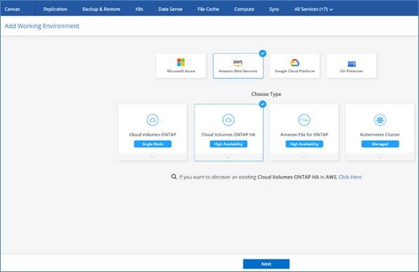
Step 3. Enter the Cluster name and credentials, add tags if needed, then click Continue.

Step 4. Keep the services enabled or disable the individual services that you don’t want to use with Cloud Volumes ONTAP.
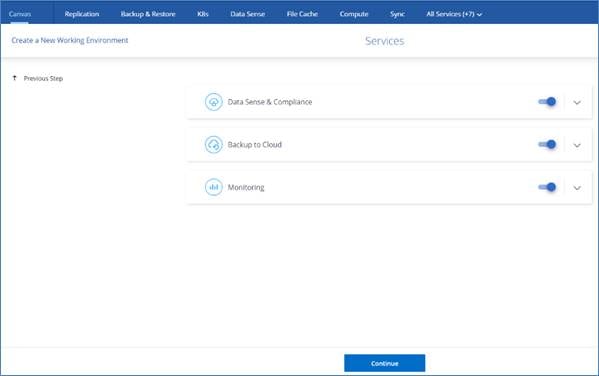
Step 5. On the HA Deployment page click Single Availability Zone.
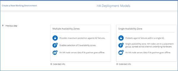
Step 6. Enter the network information that you recorded in the Network information sheet for Connector and CVO.
Step 7. Select the SSH Authentication Method of your choice for CVO HA and Mediator.
Note: If you need to use your own, refer to Security group rules.
Step 8. Click AWS Managed Encryption and click Continue.
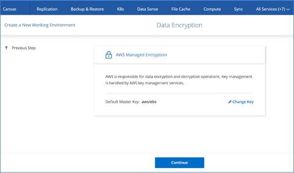
Step 9. On the Charging Methods and NSS Account, specify which charging option you would like to use with this system, specify a NetApp Support Site account, and then click Continue.

Note: The subnet should have internet connectivity through NAT device or proxy server.
Step 10. On the Preconfigured Packages, select one of the packages to quickly launch Cloud Volumes ONTAP or click Change Configuration to select your own configuration.
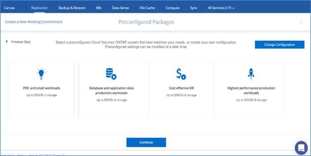
Step 11. On the Create Volume page, click Skip. You will create a volume at a later stage.
Step 12. Review the configuration and accept both options, then click Go.
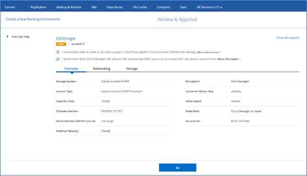
The single node CVO deployment is initiated.

The CVO instance deployment progress can be tracked in the timeline from the All Services drop-down list.
Note: The CVO deployment should take about 30 minutes.
Procedure 4. Deploy CVO HA Pair Multi-AZ
Note: Cloud Manager automatically allocates the required number of private IP addresses to Cloud Volumes ONTAP. You need to ensure that your networking has enough private IP addresses available.
Step 1. On the Canvas page, click Add Working Environment.

Step 2. Click Amazon Web Services, then click Cloud Volume ONTAP Single Node, and click Next.
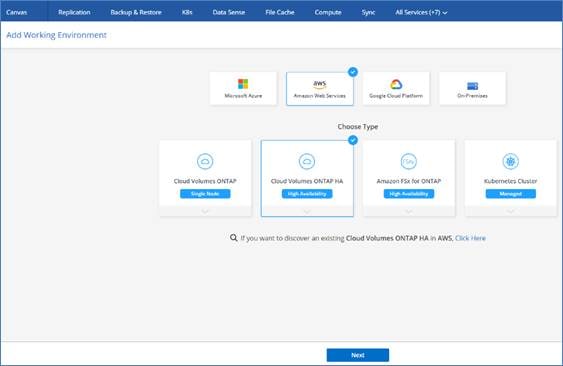
Step 3. Enter the Cluster name and credentials, add tags if needed, then click Continue.
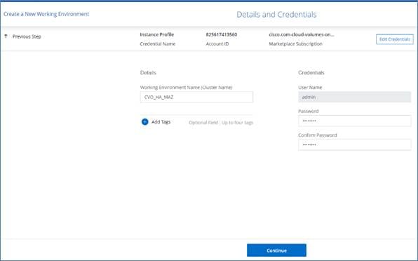
Step 4. Keep the services enabled or disable the individual services that you don’t want to use with Cloud Volumes ONTAP.

Step 5. On the HA Deployment page, click Multiple Availability Zone.
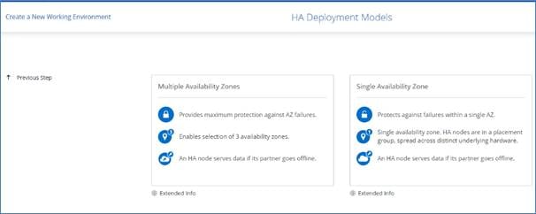
Step 6. Enter the network information that you recorded in the Network information sheet for Multi AZ CVO HA Pair.
Step 7. Select the SSH Authentication Method of your choice for CVO HA and Mediator.
Note: If you need to use your own, refer to Security group rules.
Step 8. Specify the floating IP addresses.
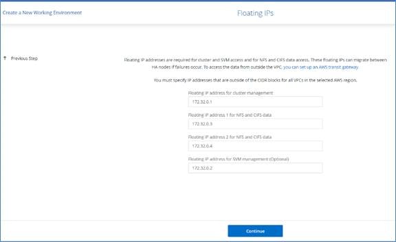
Note: You must specify the IP addresses that are outside of the CIDR blocks for all VPCs in the selected region and it should not overlap with on-prem subnets defined in Site-to-Site VPN static route.
Step 9. Select the route tables that should include routes to the floating IP addresses.
Step 10. Click AWS Managed Encryption and then click Continue.

Step 11. On the Charging Methods and NSS Account, specify which charging option you would like to use with this system, and specify a NetApp Support Site account, then click Continue.

Note: The subnet should have internet connectivity through NAT device or proxy server.
Step 12. On the Preconfigured Packages, select one of the packages to quickly launch Cloud Volumes ONTAP or click Change Configuration to select your own configuration.

Step 13. On the Create Volume page, click Skip. You will create a volume at a later stage.
Step 14. Review the configuration and check both options, then click Go.
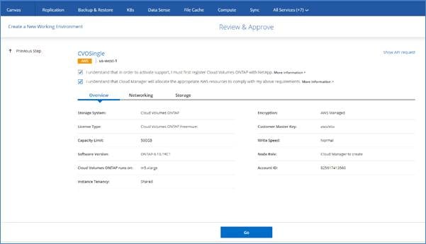
The multi-AZ HA pair CVO deployment is initiated.
CVO instance deployment progress can be tracked in the timeline from the All Services drop-down list.
Note: CVO deployment should take about 30 minutes.
Procedure 5. Additional network configuration for CVO HA Multi-AZ in AWS
Note: The floating IPs are not accessible from outside of the VPC and to make them accessible a transit gateway is required.
Step 1. Login to AWS management console and go to VPC.
Step 2. Under Transit Gateways, click Transit gateway and then create transit gateway.
Note: Enter the name and description (optional), then provide the ASN number for the AWS side.
Step 3. Leave the default checkbox selected and click Create transit gateway.
Step 4. Click Transit Gateway Attachments, enter the name, select the transit gateway created in previous step and select the attachment type, which is VPC in this scenario.
Step 5. Under VPC attachment, leave the checkbox selected and click the VPC which the CVO is deployed.
Step 6. Click Create transit gateway attachment.
Step 7. Create routes in the transit gateway’s route table by specifying the HA pairs floating IP. Under Transit gateway route tables, go to Routes and click Create static route.
Step 8. Enter all 4 floating IPs individually and select the transit gateway attachment.
This section provides links to additional information for each partner’s solution component of this document.
Demo
Short demo of the solution is available at: https://www.youtube.com/watch?v=45xKMkz5YJk
GitHub
All Terraform Configurations used are available at: https://github.com/ucs-compute-solutions/cvo_snapmirror
JSON files for importing workflows: https://github.com/ucs-compute-solutions/FlexPod_DR_Workflows
Cisco Intersight
Cisco Intersight Help Center: https://intersight.com/help/saas/home
Cisco Intersight Cloud Orchestrator Documentation: https://intersight.com/help/saas/features/orchestration/configure#intersight_cloud_orchestrator
Cisco Intersight Service for HashiCorp Terraform Documentation: https://intersight.com/help/saas/features/terraform_cloud/admin
Cisco Intersight Data Sheet: https://www.cisco.com/c/en/us/products/collateral/cloud-systems-management/intersight/intersight-ds.html
Cisco Intersight Cloud Orchestrator Data Sheet: https://www.cisco.com/c/en/us/products/collateral/cloud-systems-management/intersight/nb-06-intersight-cloud-orch-aag-cte-en.html
Cisco Intersight Service for HashiCorp Terraform Data Sheet: https://www.cisco.com/c/en/us/products/collateral/cloud-systems-management/intersight/nb-06-intersight-terraf-ser-aag-cte-en.html
FlexPod
FlexPod Home Page: https://www.flexpod.com
Cisco Validated Design and deployment guides for FlexPod: https://www.cisco.com/c/en/us/solutions/design-zone/data-center-design-guides/flexpod-design-guides.html
Cisco Validated Design for FlexPod: https://www.cisco.com/c/en/us/td/docs/unified_computing/ucs/UCS_CVDs/flexpod_m6_esxi7u2_design.html
FlexPod Datacenter with Cisco UCS X-Series: https://www.cisco.com/c/en/us/td/docs/unified_computing/ucs/UCS_CVDs/flexpod_xseries_esxi7u2_design.html
FlexPod deployment with Infrastructure as code using Ansible: https://www.cisco.com/c/en/us/td/docs/unified_computing/ucs/UCS_CVDs/flexpod_m6_esxi7u2.html#AnsibleAutomationWorkflowandSolutionDeployment
Interoperability
NetApp Interoperability Matrix Tool: http://support.netapp.com/matrix/
Cisco UCS Hardware and Software Interoperability Tool: http://www.cisco.com/web/techdoc/ucs/interoperability/matrix/matrix.html
VMware Compatibility Guide: http://www.vmware.com/resources/compatibility/search.php
NetApp Cloud Volume ONTAP Reference Documents
NetApp Cloud Manager: https://docs.netapp.com/us-en/occm/concept_overview.html
Cloud Volumes ONTAP: https://docs.netapp.com/us-en/occm/task_getting_started_aws.html
Cloud Volumes ONTAP TCO Calculator: https://cloud.netapp.com/aws-calculator
Cloud Volumes ONTAP Sizer: https://cloud.netapp.com/cvo-sizer
Cloud Assessment Tool: https://cloud.netapp.com/assessments
NetApp Hybrid Cloud: https://cloud.netapp.com/hybrid-cloud
Cloud Manager API documentation: https://docs.netapp.com/us-en/occm/reference_infrastructure_as_code.html
Troubleshooting Issues: https://kb.netapp.com/Advice_and_Troubleshooting/Cloud_Services/Cloud_Volumes_ONTAP_(CVO)
Terraform
Terraform Cloud: https://www.terraform.io/cloud
Terraform Documentation: https://www.terraform.io/docs/
NetApp Cloud Manager Registry: https://registry.terraform.io/providers/NetApp/netapp-cloudmanager/lates
AWS
AWS Market Place: https://aws.amazon.com/marketplace
AWS Site-to-Site VPN Documentation: https://docs.aws.amazon.com/vpn/
AWS Direct connect Documentation: https://docs.aws.amazon.com/directconnect/latest/UserGuide/direct-connect-gateways-intro.html
AWS transit gateways Documentation: https://docs.aws.amazon.com/vpc/latest/tgw/working-with-transit-gateways.html
Paniraja Koppa, Technical Marketing Engineer, Cisco Systems, Inc.
Paniraja Koppa works in Cisco’s Cloud and Compute Group with a primary focus on data center and cloud technologies. In his current role, he works on design and development, best practices, optimization, automation and technical content creation of compute and hybrid cloud solutions. Previously, he led QA efforts for four new virtual adapter cards for Cisco UCS. He also worked as a technical consulting engineer in the Data Center Virtualization space. Paniraja holds a master’s degree in Computer Science. He has presented several papers at international conferences and as a speaker at events like Cisco Live US and Europe, Open Infrastructure Summit, and other partner events.
Arvind Ramakrishnan, Sr. Solutions Architect, Hybrid Cloud Infrastructures, NetApp Inc.
Arvind focusses on development, validation and implementation of Hybrid Cloud Infrastructure solutions that include NetApp products. He has more than 10 years of experience in the IT industry specializing in Data Management, Security, Cloud and Data Center technologies. Arvind holds a bachelor’s degree in Electronics and Communication and a master’s degree in Compute Systems and Infrastructure. He is a speaker at multiple international conferences and is recognized as a Distinguished Speaker at Cisco Live.
Abhinav Singh, Technical Marketing Engineer, Hybrid Cloud Infrastructures, NetApp Inc.
Abhinav has more than 11 years of experience in Data Center infrastructure solutions which includes On-prem and Hybrid cloud Infrastructure. He focuses on the designing, validating, developing, and implementing cloud infrastructure solutions that include NetApp products. Abhinav holds multiple certifications like CCNP Enterprise, Cisco Specialist - Data Center Core, VCP (DCV, NSX-T), NSX-V Implementation Expert. Abhinav holds a bachelor's degree in Electrical and Electronics.
For their support and contribution to the design, validation, and creation of this Cisco Validated Design, we would like to acknowledge the significant contribution and expertise that resulted in developing this document:
● Chris O'Brien, Director, UCS Solutions, Cloud and Compute Group, Cisco Systems, Inc.
● John George, Technical Marketing Engineer, Cisco Systems, Inc.
● Haseeb Niazi, Principal Technical Marketing Engineer, Cisco Systems, Inc.
● Dileep Banavasae, Software Engineer, Cisco Systems, Inc.
● Subbu Chandrasekaran, Principal Engineer, Cisco Systems, Inc.
● Shruthi Ravindranath, Technical Leader, Cisco Systems, Inc.
● Laurent Nicolas, Principal Engineer, NetApp, Inc.
● Bobby Oommen, Senior Manager, FlexPod Solutions, NetApp Inc.
● Eran Darzi, Director Software Engineer, CVO, NetApp, Inc
● Arun Garg, Director Product Management, FlexPod
● Carol Chan, FlexPod Product Management, NetApp
For comments and suggestions about this guide and related guides, join the discussion on Cisco Community at https://cs.co/en-cvds.