FlashStack Virtual Server Infrastructure for VMware vSphere 7.0 U2 Design Guide
Available Languages
Bias-Free Language
The documentation set for this product strives to use bias-free language. For the purposes of this documentation set, bias-free is defined as language that does not imply discrimination based on age, disability, gender, racial identity, ethnic identity, sexual orientation, socioeconomic status, and intersectionality. Exceptions may be present in the documentation due to language that is hardcoded in the user interfaces of the product software, language used based on RFP documentation, or language that is used by a referenced third-party product. Learn more about how Cisco is using Inclusive Language.
- US/Canada 800-553-2447
- Worldwide Support Phone Numbers
- All Tools
 Feedback
 Feedback

FlashStack Virtual Server Infrastructure for VMware vSphere 7.0 U2 Design Guide
Published: November 2021
![]()
In partnership with:
![]()
About the Cisco Validated Design Program
The Cisco Validated Design (CVD) program consists of systems and solutions designed, tested, and documented to facilitate faster, more reliable, and more predictable customer deployments. For more information, go to:
http://www.cisco.com/go/designzone.
ALL DESIGNS, SPECIFICATIONS, STATEMENTS, INFORMATION, AND RECOMMENDATIONS (COLLECTIVELY, "DESIGNS") IN THIS MANUAL ARE PRESENTED "AS IS," WITH ALL FAULTS. CISCO AND ITS SUPPLIERS DISCLAIM ALL WARRANTIES, INCLUDING, WITHOUT LIMITATION, THE WARRANTY OF MERCHANTABILITY, FITNESS FOR A PARTICULAR PURPOSE AND NONINFRINGEMENT OR ARISING FROM A COURSE OF DEALING, USAGE, OR TRADE PRACTICE. IN NO EVENT SHALL CISCO OR ITS SUPPLIERS BE LIABLE FOR ANY INDIRECT, SPECIAL, CONSEQUENTIAL, OR INCIDENTAL DAMAGES, INCLUDING, WITHOUT LIMITATION, LOST PROFITS OR LOSS OR DAMAGE TO DATA ARISING OUT OF THE USE OR INABILITY TO USE THE DESIGNS, EVEN IF CISCO OR ITS SUPPLIERS HAVE BEEN ADVISED OF THE POSSIBILITY OF SUCH DAMAGES.
THE DESIGNS ARE SUBJECT TO CHANGE WITHOUT NOTICE. USERS ARE SOLELY RESPONSIBLE FOR THEIR APPLICATION OF THE DESIGNS. THE DESIGNS DO NOT CONSTITUTE THE TECHNICAL OR OTHER PROFESSIONAL ADVICE OF CISCO, ITS SUPPLIERS OR PARTNERS. USERS SHOULD CONSULT THEIR OWN TECHNICAL ADVISORS BEFORE IMPLEMENTING THE DESIGNS. RESULTS MAY VARY DEPENDING ON FACTORS NOT TESTED BY CISCO.
CCDE, CCENT, Cisco Eos, Cisco Lumin, Cisco Nexus, Cisco StadiumVision, Cisco TelePresence, Cisco WebEx, the Cisco logo, DCE, and Welcome to the Human Network are trademarks; Changing the Way We Work, Live, Play, and Learn and Cisco Store are service marks; and Access Registrar, Aironet, AsyncOS, Bringing the Meeting To You, Catalyst, CCDA, CCDP, CCIE, CCIP, CCNA, CCNP, CCSP, CCVP, Cisco, the Cisco Certified Internetwork Expert logo, Cisco IOS, Cisco Press, Cisco Systems, Cisco Systems Capital, the Cisco Systems logo, Cisco Unified Computing System (Cisco UCS), Cisco UCS B-Series Blade Servers, Cisco UCS C-Series Rack Servers, Cisco UCS S-Series Storage Servers, Cisco UCS Manager, Cisco UCS Management Software, Cisco Unified Fabric, Cisco Application Centric Infrastructure, Cisco Nexus 9000 Series, Cisco Nexus 7000 Series. Cisco Prime Data Center Network Manager, Cisco NX-OS Software, Cisco MDS Series, Cisco Unity, Collaboration Without Limitation, EtherFast, EtherSwitch, Event Center, Fast Step, Follow Me Browsing, FormShare, GigaDrive, HomeLink, Internet Quotient, IOS, iPhone, iQuick Study, LightStream, Linksys, MediaTone, MeetingPlace, MeetingPlace Chime Sound, MGX, Networkers, Networking Academy, Network Registrar, PCNow, PIX, PowerPanels, ProConnect, ScriptShare, SenderBase, SMARTnet, Spectrum Expert, StackWise, The Fastest Way to Increase Your Internet Quotient, TransPath, WebEx, and the WebEx logo are registered trademarks of Cisco Systems, Inc. and/or its affiliates in the United States and certain other countries. (LDW_P)
All other trademarks mentioned in this document or website are the property of their respective owners. The use of the word partner does not imply a partnership relationship between Cisco and any other company. (0809R)
© 2021 Cisco Systems, Inc. All rights reserved.
Contents
Cisco Validated Designs (CVDs) consist of systems and solutions that are designed, tested, and documented to facilitate and improve customer deployments. These designs incorporate a wide range of technologies and products into a portfolio of solutions that have been developed to address the business needs of our customers.
This document discusses the design principles that go into the FlashStack™ solution, which is a validated Converged Infrastructure (CI) jointly developed by Cisco and Pure Storage. The solution is a predesigned, best-practice data center architecture with VMware vSphere built on the Cisco Unified Computing System (Cisco UCS), the Cisco Nexus® 9000 family of switches, Cisco MDS 9000 family of Fibre Channel switches and Pure Storage FlashArray//X R3 all flash array supporting either iSCSI or Fibre Channel storage access.
In addition to that, this FlashStack solution is also delivered as Infrastructure as Code (IaC) to eliminate error-prone manual tasks, allowing quicker and more consistent solution deployments. Cisco Intersight cloud platform delivers monitoring, orchestration, workload optimization and lifecycle management capabilities for the FlashStack solution.
The solution architecture presents a robust infrastructure viable for a wide range of application workloads implemented as a Virtual Server Infrastructure (VSI).
Introduction
In the current industry there is a trend for pre-engineered solutions which standardize the data center infrastructure, offering the business operational efficiencies, agility, and scale to address cloud, bi-modal IT, and their business. Their challenge is complexity, diverse application support, efficiency, and risk; all these are met by FlashStack with:
● Reduced complexity, automatable infrastructure and easily deployed resources
● Robust components capable of supporting high performance and high bandwidth virtualized applications
● Efficiency through optimization of network bandwidth and in-line storage compression with de-duplication
● Risk reduction at each level of the design with resiliency built into each touch point
● Cloud based monitoring, management, and support of your physical and virtual infrastructure.
Cisco and Pure Storage have partnered to deliver this Cisco Validated Design, which uses best of breed storage, server, and network components to serve as the foundation for virtualized workloads, enabling efficient architectural designs that can be quickly and confidently deployed.
This document describes a reference architecture detailing a Virtual Server Infrastructure composed of Cisco Nexus switches, Cisco UCS Compute, Cisco MDS Multilayer Fabric Switches, and a Pure Storage FlashArray//X50 R3 delivering VMware vSphere 7.0 U2 hypervisor environment.
Audience
The intended audience of this document includes but is not limited to data scientists, IT architects, sales engineers, field consultants, professional services, IT managers, partner engineering, DevOps, and Site Reliability Engineers (SREs) and customers who want to take advantage of an infrastructure built to deliver IT efficiency and enable IT innovation.
Purpose of this Document
This document discusses the design for FlashStack, implemented with either FC or iSCSI, centered around the Cisco UCS 6454 Fabric Interconnect and the Pure Storage FlashArray//X50 R3, delivering a Virtual Server Infrastructure on Cisco UCS B200 M6 Blade Servers running VMware vSphere 7.0 U2.
The manual and automated deployment of these designs will be detailed in FlashStack Virtual Server Infrastructure Deployment Guide for this solution.
What’s New in this Release?
This version of the FlashStack VSI Design introduces the Cisco UCS M6 Servers featuring the 3rd Gen Intel Xeon Scalable processors. The design incorporates options for 25Gb iSCSi as well as 32Gb Fibre Channel protocols, both delivered with new design options and features. Highlights for this design include:
● Support for Cisco UCS B200 M6 blade servers with 3rd Gen Intel Xeon Scalable Family processors and 3200 MHz memory
● Support for Intel Optane Persistent Memory (PMem)
● Support for the Cisco UCS Manager 4.2
● Support for Pure Storage FlashArray//X50 R3 with Purity version 6.1.6
● Support for NVMe over Fibre Channel (FC-NVMe) Datastores
● Support for VMware vSphere 7.0 U2
● Fully automated solution deployment covering FlashStack infrastructure and vSphere virtualization
● Support for Cisco Intersight Software as a Service (SaaS) Management
● Support for Cisco Data Center Network Manager (DCNM)-SAN Version 11.5(1)
● Unified Extensible Firmware Interface (UEFI) Secure Boot of VMware ESXi 7.0 Update 2
● Trusted Platform Module (TPM) 2.0 Attestation of UEFI Secure Boot of VMware ESXi 7.0 Update 2
Solution Summary
FlashStack provides a jointly supported solution by Cisco and Pure Storage. Bringing a carefully validated architecture built on superior compute, world class networking, and the leading innovations in all flash storage. These components are integrated and validated, and the entire stack is automated so that customers can deploy the solution quickly and efficiently while eliminating many of the risks associated with researching, designing, building, and deploying similar solutions from the ground up.
The portfolio of validated offerings from FlashStack includes but is not limited to the following:
● Consistent performance: FlashStack provides higher, more consistent performance than disk-based solutions and delivers a converged infrastructure based on all-flash that provides non-disruptive upgrades and scalability.
● Cost savings: FlashStack uses less power, cooling, and data center space when compared to legacy disk/hybrid storage. It provides industry-leading storage data reduction and exceptional storage density.
● Simplicity: FlashStack requires low ongoing maintenance and reduces operational overhead. It also scales simply and smoothly in step with business requirements.
● Deployment choices: It is available as a custom-built single unit from FlashStack partners, but organizations can also deploy using equipment from multiple sources, including equipment they already own.
● Unique business model: The Pure Storage Evergreen Storage Model enables companies to keep their storage investments forever, which means no more forklift upgrades and no more downtime.
● Mission-critical resiliency: FlashStack offers best in class performance by providing active-active resiliency, no single point of failure, and non-disruptive operations, enabling organizations to maximize productivity.
● Support choices: Focused, high-quality single number reach for FlashStack support is available from FlashStack Authorized Support Partners. Single-number support is also available directly from Cisco Systems as part of the Cisco Solution Support for Data Center offering. Support for FlashStack components is also available from Cisco, VMware, and Pure Storage individually and leverages TSANet for resolution of support queries between vendors.
The FlashStack architecture is comprised of the following infrastructure components for compute, network, and storage:
● Cisco Unified Computing System (Cisco UCS)
● Cisco Nexus and Cisco MDS Switches
● Pure FlashArray
Figure 1. FlashStack for Virtual Server Infrastructure – Components
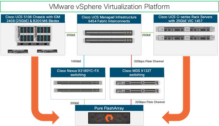
These components are connected and configured according to the best practices of both Cisco and Pure and provide an ideal platform for running a variety of workloads with confidence. One of the key benefits of FlashStack is the ability to maintain consistency at both scale-up and scale-out models. The current solution comprises of following core components:
The FlashStack reference architecture explained in this document leverages:
● Cisco UCS Manager on Cisco 4th generation 6454 Fabric Interconnects to support 10GbE, 25GbE and 100GbE connectivity from various components.
● Cisco UCS 5108 Chassis with Cisco UCS B200 M6 blade servers and support for Cisco B200 M5, Cisco UCS C220 M5 rack servers and Cisco UCS C4200 chassis with Cisco UCS C125 M5 nodes to support vSphere virtualization.
● High-Speed Cisco NX-OS based Nexus 93180YC-FX switching design to support up to 100GbE connectivity.
● High-Speed Cisco NX-OS based MDS 9132T switching design to support up to 32Gb connectivity to support SCSI and NVMe end-to-end over Fibre Channel.
● Pure FlashArray//X R3 ALL-NVMe storage with 25GbE connectivity to Cisco Nexus switching fabric.
● Pure FlashArray//X R3 ALL-NVMe storage with 32Gb FC connectivity to Cisco MDS switching fabric.
● VMware vSphere 7.0 U2
The key features and highlights for these FlashStack components are explained in the following sections.
Cisco Unified Computing System
Cisco Unified Computing System™ (Cisco UCS®) is an integrated computing infrastructure with intent-based management to automate and accelerate deployment of all your applications, including virtualization and cloud computing, scale-out and bare metal workloads, and in-memory analytics, as well as edge computing that supports remote and branch locations and massive amounts of data from the Internet of Things (IoT). The system is flexible, agile, and adaptable, and the portfolio of products supported by Cisco UCS includes blade, rack, multinode, and storage-intensive servers; converged infrastructure; hyperconverged infrastructure (Cisco HyperFlex™ systems); and solutions for the network edge such as Cisco UCS Mini and Cisco HyperFlex Edge. Cisco UCS supports blade, rack, multinode, and storage servers in a single domain of up to 160 servers.
Cisco UCS B200 M6 Blade Servers
The enterprise-class Cisco UCS B200 M6 blade server shown in Figure 2 extends the capabilities of Cisco’s Unified Computing System portfolio in a half-width blade form factor
Figure 2. Cisco UCS B200 M6 Blade Server
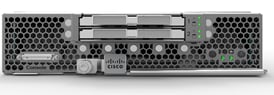
The Cisco UCS B200 M6 server is the follow-on server to the popular Cisco UCS B200 M5 server and includes support for the following:
● Up to two 3rd Gen Intel Xeon Scalable processors (with up to 40 cores per socket)
● Memory:
◦ 32 DIMM slots (16 DIMMs per CPU socket)
◦ 3200 MHz DDR4 memory plus other speeds depending on the CPU installed.
◦ 32x DDR4 DIMMs for up to 8 TB of capacity using 256 GB DIMMs, or
◦ 16x DDR4 DIMMs + 16x Intel Optane™ persistent memory modules for up to 12 TB of memory
● Up to 3 PCIe 4.0 slots plus a modular LAN on Motherboard (mLOM) slot
● Support for Cisco UCS VIC 1400 Series adapters as well as third-party options
● Up to two SATA/NVMe disk drives or up to four M.2 drives
● Up to two GPUs supported
For more information about the Cisco UCS B200 M6 Blade Servers, see: https://www.cisco.com/c/en/us/products/collateral/servers-unified-computing/ucs-b-series-blade-servers/datasheet-c78-2368888.html
Cisco UCS 6400 series Fabric Interconnects
The Cisco UCS Fabric Interconnects (FIs) provide a single point for connectivity and management for the entire Cisco UCS system. Typically deployed as an active-active pair, the system’s FIs integrate all components into a single, highly available management domain controlled by the Cisco UCS Manager. Cisco UCS FIs provide a single unified fabric for the system, with low-latency, lossless, cut-through switching that supports LAN, SAN and management traffic using a single set of cables.
The Cisco UCS 6454 (Figure 3 ) deployed for this validation, provides the management and communication backbone for the Cisco UCS B-Series Blade Servers, Cisco UCS 5108 B-Series Server Chassis and Cisco UCS Managed C-Series Rack Servers. All servers attached to the Cisco UCS 6454 Fabric Interconnect become part of a single, highly available management domain. In addition, by supporting a unified fabric, the Cisco UCS 6454 provides both the LAN and SAN connectivity for all servers within its domain. The Cisco UCS 6454 supports deterministic, low-latency, line-rate 10/25/40/100 Gigabit Ethernet ports, a switching capacity of 3.82 Tbps, and 320 Gbps bandwidth between FI 6454 and IOM 2208 per 5108 blade chassis, independent of packet size and enabled services
Figure 3. Cisco UCS 6400 Series Fabric Interconnect

Cisco UCS 2408 Fabric Extender
The Cisco UCS 2408 connects the I/O fabric between the Cisco UCS 6454 Fabric Interconnect and the Cisco UCS 5100 Series Blade Server Chassis, enabling a lossless and deterministic converged fabric to connect all blades and chassis together.
The Cisco UCS 2408 Fabric Extender has eight 25-Gigabit Ethernet, FCoE-capable, Small Form-Factor Pluggable (SFP28) ports that connect the blade chassis to the fabric interconnect. Each Cisco UCS 2408 provides 10-Gigabit Ethernet ports connected through the midplane to each half-width slot in the chassis, giving it a total 32 10G interfaces to UCS blades. Typically configured in pairs for redundancy, two fabric extenders provide up to 400 Gbps of I/O from FI 6400s to 5108 chassis.
Cisco UCS 1400 Series Virtual Interface Cards (VICs)
Cisco VICs support Cisco SingleConnect technology, which provides an easy, intelligent, and efficient way to connect and manage computing in your data center. Cisco SingleConnect unifies LAN, SAN, and systems management into one simplified link for rack servers and blade servers. This technology reduces the number of network adapters, cables, and switches needed and radically simplifies the network, reducing complexity. Cisco VICs can support 256 Express (PCIe) virtual devices, either virtual Network Interface Cards (vNICs) or virtual Host Bus Adapters (vHBAs), with a high rate of I/O Operations Per Second (IOPS), support for lossless Ethernet, and 10/25/40/100-Gbps connection to servers. The PCIe Generation 3 x 16 interface helps ensure optimal bandwidth to the host for network-intensive applications, with a redundant path to the fabric interconnect. Cisco VICs support NIC teaming with fabric failover for increased reliability and availability. In addition, it provides a policy-based, stateless, agile server infrastructure for your data center.
The Cisco VIC 1400 series is designed for Cisco UCS B-Series and X-Series M5 and M6 Blade Servers, Cisco UCS C-Series M5 and M6 Rack Servers, and Cisco S-Series M5 Storage Servers. The adapters are capable of supporting 10/25/40/100-Gigabit Ethernet and Fibre Channel over Ethernet (FCoE). It incorporates Cisco’s next-generation Converged Network Adapter (CNA) technology and offers a comprehensive feature set, providing investment protection for future feature software releases. In addition, the VIC supports Cisco’s Data Center Virtual Machine Fabric Extender (VM-FEX) technology. This technology extends the Cisco UCS fabric interconnect ports to virtual machines, simplifying server virtualization deployment.
The Cisco VIC 1400 Supports NVMe capabilities by adding NVMe over Fabrics (NVMeoF) with RoCEv2 addition to existing support for NVMe over Fabrics using Fibre Channel (FC-NVMe).
Intel Optane DC Persistent Memory
Intel® Optane™ DC Persistent Memory is a new technology designed to fill the capacity, cost, and performance gaps between traditional DRAM memory and storage for servers.
While the performance of DRAM is great, it is relatively expensive and volatile (the contents disappear when the server is rebooted). SSDs, one option for storing programs and data, while faster than hard disk drives, are not nearly as fast as DIMMs, though their content isn’t volatile. Intel Optane DC Persistent Memory was designed to provide an option between DRAM and SSD, reducing the cost while potentially increasing the size of server memory and/or providing the fastest persistent storage of data. Up to half of the server’s DIMM slots can be used for Intel Optane DC Persistent Memory.
Cisco UCS introduce support for the Intel® Optane™ Data Center persistent memory modules on the Cisco UCS M5 servers that are based on the Second Generation Intel® Xeon® Scalable processors. Starting with Cisco UCS Manager Release 4.2, the support for the Intel® Optane™ Data Center persistent memory modules on the Cisco UCS M6 servers that are based on the 3rd Generation Intel® Xeon® Scalable are also provided.
With 3rd Gen Intel® Xeon® Scalable processors and Intel Optane PMem 200 series workloads can optimize performance and cost by creating a 2-tier hierarchy in memory and storage.
Intel® Optane™ Persistent Memory 200 Series
Intel® Optane™ PMem 200 series coexists side-by-side with system memory, occupying existing DRAM slots. It delivers an average of up to 32 percent more memory bandwidth than the previous generation.1 Available in 128 GB, 256 GB, and 512 GB modules, it offers both large capacity and persistence that enable new platform architectures to:
● Help accelerate large-memory computing by keeping more data closer to the CPU
● Accelerate restart times with reduced I/O by persisting data in memory and not require reloading from storage
● Reduce power consumption for large-memory nodes
This design validated DC Persistent Memory for VMware ESXi 7.0 U2 host in App Direct Mode as well as the Memory Mode with Cisco UCS M6 servers as specified in the article vSphere Support for Intel's Optane Persistent Memory (PMEM) (67645).
Cisco UCS Management
While Cisco UCS is stateless, programmable infrastructure, the Cisco UCS unified API is how management tools program it. This enables the tools to help guarantee consistent, error-free, policy-based alignment of server personalities with workloads. Through automation, transforming the server and networking components of your infrastructure into a complete solution is fast and error-free because programmability eliminates the error-prone manual configuration of servers and integration into solutions. Server, network, and storage administrators are now free to focus on strategic initiatives rather than spending their time performing tedious tasks
Cisco UCS Manager
Cisco UCS® Manager (UCSM) provides a unified, integrated management for all software and hardware components in Cisco UCS. Cisco UCSM manages a single domain through an intuitive HTML 5-based GUI which is embedded in each fabric interconnect. Running in a redundant, high-availability configuration, it creates a single, self-aware, self-integrating unified system that recognizes and integrates components as they are added to the system. It quickly and accurately configures computing, network, storage, and storage-access resources to reduce the chance of errors that can cause downtime. Its role and policy-based approach helps organizations more easily align policies and configurations with workloads. While Cisco UCS Manager requires an “always on” connection, our other tools are evolving to manage systems to which they are not continuously connected.
Cisco Intersight Software-as-a-Service Management
The Cisco Intersight platform is a software-as-a-service (SaaS) infrastructure lifecycle management platform that delivers simplified configuration, deployment, maintenance, and support. The Cisco Intersight platform is designed to be modular, so customers can adopt services based on their individual requirements. The platform significantly simplifies IT operations by bridging applications with infrastructure, providing visibility and management from bare-metal servers and hypervisors to serverless applications, thereby reducing costs and mitigating risk. This unified SaaS platform uses a unified Open API design that natively integrates with the third-party platforms and tools.
Figure 4. Cisco Intersight Overview
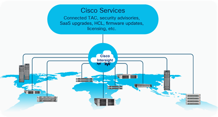
The main benefits of Cisco Intersight infrastructure services are as follows:
● Simplify daily operations by automating many daily manual tasks.
● Combine the convenience of a SaaS platform with the capability to connect from anywhere and manage infrastructure through a browser or mobile app.
● Stay ahead of problems and accelerate trouble resolution through advanced support capabilities.
● Gain global visibility of infrastructure health and status along with advanced management and support capabilities.
● Upgrade to add workload optimization and Kubernetes services when needed.
Intersight provides the following capabilities for this FlashStack solution with Cisco UCS deployed in UCS managed mode:
● Global dashboard and inventory - When you manage your FlashStack infrastructure with Cisco Intersight, you can view a global dashboard that gives you overall server status and enables you to drill down to view individual components (such as disk drives) With a global inventory of your devices, it’s easy to track the location of each of your assets.
● Cisco TAC - Delivers proactive support and Return Materials Authorizations (RMAs) through tight integration with Cisco Technical Assistance Center (TAC)
● Recommendation engine - The recommendation engine provides predictive analytics, security advisories, hardware compatibility alerts, and additional functions. Intersight has insight into your operating system and driver versions. It can use these to validate that your implementations are supported by Cisco’s Hardware Configuration List (HCL).
● Lifecycle management – Cisco Intersight provides lifecycle management of Cisco UCS servers by offering simplified firmware upgrade capabilities from the cloud platform.
DevOps and Tool Support
The Cisco UCS unified API is of great benefit to developers and administrators who want to treat physical infrastructure the way they treat other application services, using processes that automatically provision or change IT resources. Similarly, your IT staff needs to provision, configure, and monitor physical and virtual resources; automate routine activities; and rapidly isolate and resolve problems. The Cisco UCS unified API integrates with DevOps management tools and processes and enables you to easily adopt DevOps methodologies.
Pure Storage FlashArray with Intersight
The Cisco Intersight Premier edition offers private-cloud Infrastructure-as-a-Service (IaaS) orchestration across Cisco UCS, HyperFlex, and third-party endpoints including VMware vCenter and Pure Storage. This feature, called Cisco Intersight Orchestrator, enables you to create and execute workflows in Cisco Intersight. For example, provisioning a Pure Storage FlashArray or deploying a new virtual machine from a template could involve multiple tasks, but with Cisco Intersight Orchestrator, the administrator has a workflow designer to visualize a workflow definition and monitor the execution of that workflow on any infrastructure element.
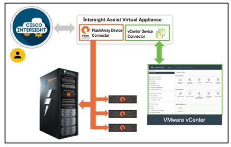
Cisco Intersight Assist
Cisco Intersight Assist helps customers add endpoint devices to Cisco Intersight. A datacenter could have multiple devices that do not connect directly with Cisco Intersight. Any device that is supported by Cisco Intersight but does not connect directly with it, will need a connection mechanism. Cisco Intersight Assist provides that connection mechanism. In FlashStack, VMware vCenter and Pure Storage FlashArray connect to Intersight with the help of Intersight Assist VM.
Cisco Intersight integrates with VMware vCenter and Pure Storage FlashArray as follows:
● Cisco Intersight uses the device connector running within Cisco Intersight Assist virtual appliance to communicate with the VMware vCenter.
● Cisco Intersight uses the device connector running within Cisco Intersight Assist virtual appliance to integrate with Pure Storage FlashArray//X50 R3.
Figure 5. Cisco Intersight, VMware vCenter and Pure Storage Integration
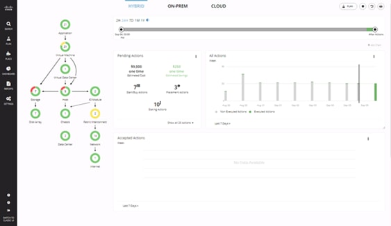
Cisco Workload Optimization Manager
Cisco Workload Optimization Manager (CWOM) is a real-time decision engine that drives continuous health in the IT environment. Its intelligent software constantly analyzes workload consumption, costs, and compliance constraints. It assures application performance by giving workloads the resources they need when required. CWOM provides specific real-time actions that ensure workloads get the resources they need for:
● Planning
● Placement
● Reports
● Overall Dashboard
The CWOM dashboard provides views specific to On-Prem, the Cloud, or a Hybrid view of infrastructure, applications, and costs across both.
Figure 6. CWOM Dashboard
For more information about the full capabilities of workload optimization, planning, and reporting, see: https://www.cisco.com/c/en/us/products/servers-unified-computing/workload-optimization-manager/index.html
Cisco Nexus
Cisco Nexus series switches provide an Ethernet switching fabric for communications between the Cisco UCS, Pure Storage controllers, and the rest of a customer’s network. There are many factors to consider when choosing the main data switch in this type of architecture to support both the scale and the protocols required for the resulting applications. All Cisco Nexus switch models including the Cisco Nexus 5000 and Cisco Nexus 7000 are supported in this design and may provide additional features such as FCoE or OTV. However, be aware that there may be slight differences in setup and configuration based on the switch used. The validation for this deployment leverages the Cisco Nexus 9000 series switches, which deliver high performance 10/25/40/50/100GbE ports, density, low latency, and exceptional power efficiency in a broad range of compact form factors.
Many of the most recent single-site FlashStack designs also use this switch due to the advanced feature set and the ability to support Application Centric Infrastructure (ACI) mode. When leveraging ACI fabric mode, the Cisco Nexus 9000 series switches are deployed in a spine-leaf architecture. Although the reference architecture covered in this design does not leverage ACI, it lays the foundation for customer migration to ACI in the future, and fully supports ACI today if required.
For more information, see: http://www.cisco.com/c/en/us/products/switches/nexus-9000-series-switches/index.html.
This FlashStack design deploys a single pair of Cisco Nexus 93180YC-FX top-of-rack switches (Figure 7) within each placement, using the traditional standalone mode running NX-OS.
Figure 7. Cisco Nexus 93180YC-FX
![]()
Cisco MDS
The Cisco® MDS 9132T 32G Multilayer Fabric Switch is the next generation of the highly reliable, flexible, and low-cost Cisco MDS 9100 Series switches. It combines high performance with exceptional flexibility and cost effectiveness. This powerful, compact one rack-unit (1RU) switch scales from 8 to 32 line-rate 32 Gbps Fibre Channel ports. The MDS 9132T Fibre Channel Switch is featured in this design as the option for the Fibre Channel network.
Figure 8. Cisco MDS 9132T
![]()
The Cisco MDS 9132T delivers advanced storage networking features and functions with ease of management and compatibility with the entire Cisco MDS 9000 Family portfolio for reliable end-to-end connectivity. This switch also offers state-of-the-art SAN analytics and telemetry capabilities that have been built into this next-generation hardware platform. This new state-of-the-art technology couples the next-generation port ASIC with a fully dedicated Network Processing Unit designed to complete analytics calculations in real time. The telemetry data extracted from the inspection of the frame headers are calculated on board (within the switch) and, using an industry-leading open format, can be streamed to any analytics-visualization platform. This switch also includes a dedicated 10/100/1000BASE-T telemetry port to maximize data delivery to any telemetry receiver including Cisco Data Center Network Manager.
Cisco Data Center Network Manager (DCNM)-SAN
Cisco DCNM-SAN can be used to monitor, configure, and analyze Cisco 32Gbps Fibre Channel fabrics and show information about the Cisco Nexus switching fabric. Cisco DCNM-SAN is deployed as a virtual appliance from an OVA and is managed through a web browser. Once the Cisco MDS and Nexus switches are added with the appropriate credentials and licensing, monitoring of the SAN and Ethernet fabrics can begin. Additionally, VSANs, Device Aliases, Zones, and Zonesets can be added, modified, and deleted using the DCNM point and click interface. Device Manager can also be used to configure the Cisco MDS switches. SAN Analytics can be added to Cisco MDS switches to provide insights into the fabric by allowing customers to monitor, analyze, identify, and troubleshoot performance issues.
Cisco DCNM Integration with Cisco Intersight
The Cisco Network Insights Base (Cisco NI Base) application provides TAC Assist functionalities which are useful when working with Cisco TAC. It provides a way for Cisco Customers to collect tech support across multiple devices and upload those tech supports to Cisco Cloud. The Cisco NI Base app collects the CPU, device name, device product id, serial number, version, memory, device type, and disk usage information for the nodes in the fabric. Cisco NI Base application is connected to the Cisco Intersight cloud portal through a Device Connector which is embedded in the management controller of the Cisco DCNM platform. The Device Connector provides a secure way for connected Cisco DCNM to send and receive information from the Cisco Intersight portal, using a secure Internet connection.
Pure Storage FlashArray
The Pure Storage FlashArray family delivers purpose-built, software-defined all-flash power and reliability for businesses of every size. FlashArray is all-flash enterprise storage that is up to 10X faster, more space and power efficient, more reliable, and far simpler than other available solutions. Critically, FlashArray also costs less, with a TCO that's typically 50% lower than traditional performance disk arrays.
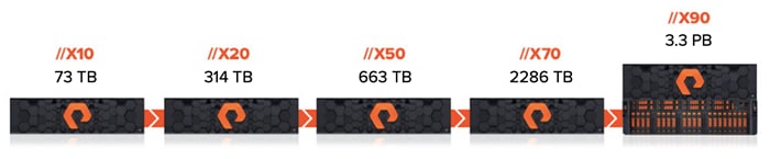
At the top of the FlashArray line is FlashArray//X – the first mainstream, 100% NVMe, enterprise-class all-flash array. //X represents a higher performance tier for mission-critical databases, top-of-rack flash deployments, and Tier 1 application consolidation. //X, at 1PB in 3U, with hundred-microsecond range latency and GBs of bandwidth, delivers an unprecedented level of performance density making possible previously unattainable levels of consolidation.
Figure 9. Pure Storage FlashArray//X R3
Purity for FlashArray (Purity//FA 6)
At the heart of every FlashArray is Purity Operating Environment software. Purity//FA6 implements advanced data reduction, storage management, and flash management features, enabling organizations to enjoy Tier 1 data services for all workloads, proven 99.9999% availability over two years (inclusive of maintenance and generational upgrades), completely non-disruptive operations, 2X better data reduction versus alternative all-flash solutions, and – with FlashArray//X – the power and efficiency of DirectFlash™. Moreover, Purity includes enterprise-grade data security, comprehensive data protection options, and complete business continuity via ActiveCluster multi-site stretch cluster. All these features are included with every array.
FlashArray//X R3 Specifications
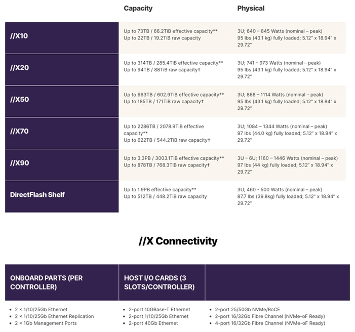
[*] Stated //X specifications are applicable to //X R3 versions.
[**] Effective capacity assumes HA, RAID, and metadata overhead, GB-to-GiB conversion, and includes the benefit of data reduction with always-on inline deduplication, compression, and pattern removal. Average data reduction is calculated at 5-to-1 and does not include thin provisioning.
[†] Array accepts Pure Storage DirectFlash Shelf and/or Pure.
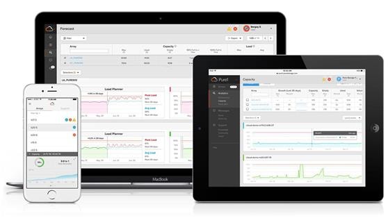
Pure1
Pure1, a cloud-based management, analytics, and support platform, expands the self-managing, plug-n-play design of Pure all-flash arrays with the machine learning predictive analytics and continuous scanning of Pure1 Meta™ to enable an effortless, worry-free data platform.
Pure1 Manage
In the Cloud IT operating model, installing, and deploying management software is an oxymoron: you simply login. Pure1 Manage is SaaS-based, allowing you to manage your array from any browser or from the Pure1 Mobile App – with nothing extra to purchase, deploy, or maintain. From a single dashboard you can manage all your arrays, with full visibility on the health and performance of your storage.
Pure1 Analyze
Pure1 Analyze delivers true performance forecasting – giving customers complete visibility into the performance and capacity needs of their arrays – now and in the future. Performance forecasting enables intelligent consolidation and unprecedented workload optimization.
Pure1 Support
Pure combines an ultra-proactive support team with the predictive intelligence of Pure1 Meta to deliver unrivaled support that’s a key component in our proven FlashArray 99.9999% availability. Customers are often surprised and delighted when we fix issues they did not even know existed.
Pure1 META
The foundation of Pure1 services, Pure1 Meta is global intelligence built from a massive collection of storage array health and performance data. By continuously scanning call-home telemetry from Pure Storage’s installed base, Pure1 Meta uses machine learning predictive analytics to help resolve potential issues and optimize workloads. The result is both a white glove customer support experience and breakthrough capabilities like accurate performance forecasting.
Meta is always expanding and refining what it knows about array performance and health, moving the Data Platform toward a future of self-driving storage.
VMware vSphere 7.0 U2
VMware vSphere is a virtualization platform for holistically managing large collections of infrastructures (resources-CPUs, storage, and networking) as a seamless, versatile, and dynamic operating environment. Unlike traditional operating systems that manage an individual machine, VMware vSphere aggregates the infrastructure of an entire data center to create a single powerhouse with resources that can be allocated quickly and dynamically to any application in need.
vSphere 7.0 U2 brings several improvements and simplifications including, but not limited to:
● VMware vSphere Virtual Volumes statistics for better debugging - track performance statistics for vSphere Virtual Volumes to quickly identify issues such as latency in third-party VASA provider responses. By using a set of commands, you can get statistics for all VASA providers in your system, or for a specified namespace or entity in the given namespace or enable statistics tracking for the complete namespace.
● vSphere Native Key Provider - Enables the use of vTPMs, vSphere Virtual Machine Encryption, and vSAN Data at Rest Encryption, when you do not require or want an external key server.
● vSphere HA support for Persistent Memory (PMEM) workloads - to deliver DRS initial placement and vSphere High Availability support for workloads that use non-volatile, persistent memory technologies.
● vSphere Lifecycle Manager fast upgrades – a replacement for VMware Update Manager, bringing a suite of capabilities to make lifecycle operations better.
● vMotion Auto Scaling - enables vSphere to automatically tune vMotion for best performance on modern, high-speed 25, 40, and 100 Gbps Ethernet networks.
For more information about VMware vSphere and its components, see: http://www.vmware.com/products/vsphere.html.
Red Hat Ansible
Ansible is simple and powerful, allowing users to easily manage various physical devices within FlashStack including the provisioning of Cisco UCS bare metal servers, Cisco Nexus switches, Pure FlashArray storage and VMware vSphere. Using Ansible’s Playbook-based automation is easy and integrates into your current provisioning infrastructure. This solution offers Ansible Playbooks that are made available from a GitHub repository that customers can access to automate the FlashStack deployment.
FlashStack with Cisco UCS M6 servers and VMware vSphere 7.0 U2 delivers a Virtual Server Infrastructure that is redundant, using the best practices of Cisco and Pure Storage. The solution includes VMware vSphere 7.0 U2 hypervisor installed on the Cisco UCS M6 compute nodes configured for stateless compute design using boot from SAN. Pure Storage FlashArray//X50 R3 provides the storage infrastructure required for setting up the VMware environment. Cisco UCS Manager is utilized to configure and manage the UCS infrastructure with Cisco Intersight providing lifecycle management capabilities. The solution requirements and design details are covered in this section.
Physical Topology
FlashStack with Cisco UCS M6 servers supports both IP and Fibre Channel (FC) based storage access design. For the IP based solution, iSCSI configuration on Cisco UCS and Pure Storage FlashArray is utilized to setup storage access including boot from SAN for the compute node. For the FC designs, Pure Storage FlashArray and Cisco UCS are connected through Cisco MDS 9132T switches and storage access utilizes the FC network. The physical connectivity details for both IP and FC designs are covered below.
IP-based Storage Access
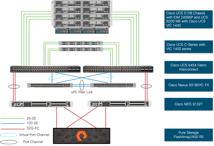
The physical topology for the IP-based FlashStack is shown in Figure 10.
Figure 10. FlashStack - Physical Topology for IP Connectivity
To validate the IP-based storage access in a FlashStack configuration, the components are set up as follows:
● Cisco UCS 6454 Fabric Interconnects provide the chassis and network connectivity.
● The Cisco UCS 5108 Modular Chassis connects to fabric interconnects using the Cisco 2408XP IOM within modules hosted within the chassis, where four 25 Gigabit Ethernet ports are used on each IOM to connect to appropriate FI. Depending on customer workload requirements, for additional bandwidth all eight ports can be used to connect IOM to FI.
● Cisco UCS B200 M6 servers contain fourth-generation Cisco 1440 virtual interface cards.
● Cisco Nexus 93180YC-FX Switches in Cisco NX-OS mode provide the switching fabric.
● Cisco UCS 6454 Fabric Interconnect 100 Gigabit Ethernet uplink ports connect to Cisco Nexus 93180YC-FX Switches in a virtual port channel (vPC) configuration.
● The Pure Storage FlashArray//X50 R3 connects to the Cisco Nexus 93180YC-FX Switches using four 25 GE ports.
● VMware 7.0 U2 ESXi software is installed on Cisco UCS B200 M6 servers to validate the infrastructure.
FC-based Storage Access
The physical topology for the FC-based FlashStack is shown in Figure 11.
Figure 11. FlashStack - Physical Topology for FC Connectivity
To validate the FC based storage access in a FlashStack configuration, the components are set up as follows:
● Cisco UCS 6454 Fabric Interconnects provide the chassis and network connectivity.
● The Cisco UCS 5108 Modular Chassis connects to fabric interconnects using the Cisco 2408XP IOM within modules hosted within the chassis, where four 25 Gigabit Ethernet ports are used on each IOM to connect to the appropriate FI.
● Cisco UCS B200 M6 servers contain fourth-generation Cisco 1440 virtual interface cards.
● Cisco Nexus 93180YC-FX Switches in Cisco NX-OS mode provide the switching fabric.
● Cisco UCS 6454 Fabric Interconnect 100 Gigabit Ethernet uplink ports connect to Cisco Nexus 93180YC-FX3 Switches in a virtual port channel (vPC) configuration.
● Cisco UCS 6454 Fabric Interconnects are connected to the Cisco MDS 9132T switches using 32-Gbps Fibre Channel connections configured as a port channel for SAN connectivity.
● The Pure Storage FlashArray//X50 R3 connects to each Cisco MDS 9132T switches to provide redundant paths through both the fabrics using 32-Gbps Fibre Channel connections for SAN connectivity.
● VMware 7.0 U2 ESXi software is installed on Cisco UCS B200 M6 servers to validate the infrastructure.
VLAN Configuration
Table 1 list VLANs configured for setting up the FlashStack environment along with their usage:
Table 1. VLAN Usage
| VLAN ID |
Name |
Usage |
| 2 |
Native-VLAN |
Use VLAN 2 as Native VLAN instead of default VLAN (1). |
| 15 |
OOB-MGMT-VLAN |
Out-of-Band Management VLAN to connect the management ports for various devices. |
| 115 |
IB-MGMT-VLAN |
In Band Management VLAN utilized for all in-band management connectivity for example, ESXi hosts, VM management and so on. |
| 1101 |
VM-Traffic-VLAN |
VM data traffic VLAN. |
| 1130 |
vMotion-VLAN |
VMware vMotion traffic. |
| 901* |
iSCSI-A-VLAN |
iSCSI-A path for supporting boot-from-san for both Cisco UCS B-Series and Cisco UCS C-Series servers. |
| 902* |
iSCSI-B-VLAN |
iSCSI-A path for supporting boot-from-san for both Cisco UCS B-Series and Cisco UCS C-Series servers. |
* iSCSI VLANs are not required when using FC storage access.
Some of the key highlights of VLAN usage are as follows:
● VLAN 15 allows customers to manage and access out of band management interfaces of various devices.
● VLAN 115 is used for in-band management of VM, ESXi hosts and other infrastructure services.
● A pair of iSCSI VLANs (901 and 902) are configured to provide access to boot LUNs for ESXi hosts. These VLANs are not needed when configuring Fibre Channel connectivity.
Logical Topology
In FlashStack deployments, each Cisco UCS server equipped with a Cisco Virtual Interface Card (VIC) is configured for multiple virtual network interfaces (vNICs) which appear as standards-compliant PCIe endpoints to the OS. The end-to-end logical connectivity including VLAN/VSAN usage between the service profile for an ESXi host and the storage configuration on Pure Storage FlashArray is captured in the following sub-sections.
Logical Topology for IP-based Storage Access
Figure 12 illustrates the end-to-end connectivity design for IP-based storage access.
Figure 12. Logical Connectivity for iSCSI Design
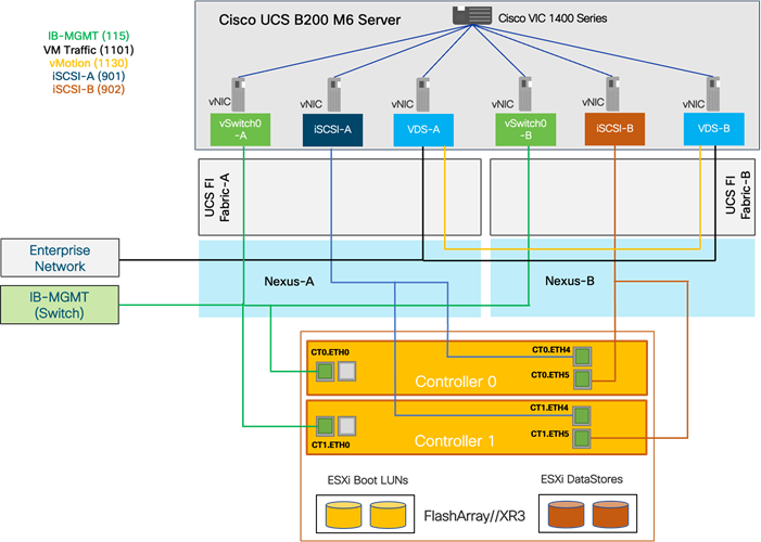
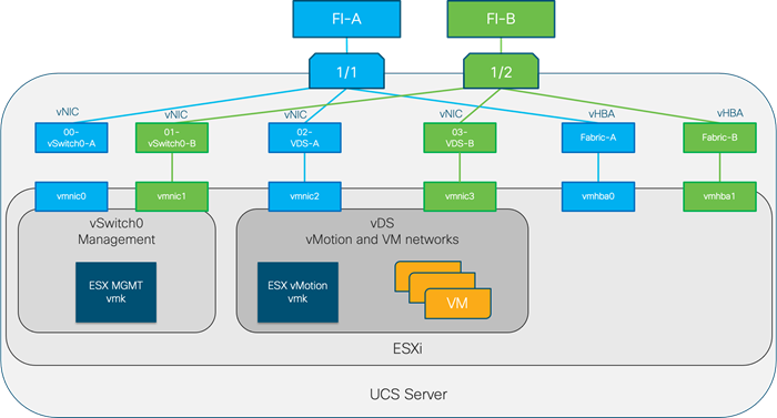
Each ESXi host server profile supports:
● Managing the ESXi hosts using a common management segment
● Diskless SAN boot using iSCSI with persistent operating system installation for true stateless computing
● Six vNICs where:
◦ 2 redundant vNICs (vSwitch0-A and vSwitch0-B) carry management traffic. The MTU value for these vNICs is set as a Jumbo MTU (9000).
◦ 2 redundant vNICs (VDS-A and VDS-B) are used by the vSphere Distributed switch and carry VMware vMotion traffic and customer application data traffic. The MTU for the vNICs is set to Jumbo MTU (9000).
◦ 1 iSCSI-A vNIC used by iSCSI-A vSwitch to provide access to iSCSI-A path. The MTU value for the vNIC is set to Jumbo MTU (9000).
◦ 1 iSCSI-B vNIC used by iSCSI-B vSwitch to provide access to iSCSI-B path. The MTU value for this vNIC is set to Jumbo MTU (9000).
● Each ESXi host (compute node) accesses VM datastores from Pure Storage FlashArray using iSCSI for deploying virtual machines.
Logical Topology for FC-based Storage Access
Figure 13 illustrates the end-to-end connectivity design for FC-based storage access.
Figure 13. Logical Connectivity for FC Design
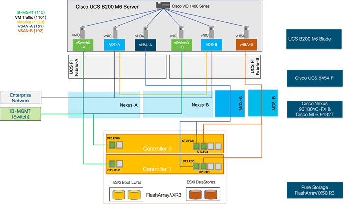
Each ESXi server profile supports:
● Managing the ESXi hosts using a common management segment
● Diskless SAN boot using FC with persistent operating system installation for true stateless computing
● Four vNICs where:
◦ 2 redundant vNICs (vSwitch0-A and vSwitch0-B) carry management traffic. The MTU value for these vNICs is set as a Jumbo MTU (9000).
◦ 2 redundant vNICs (VDS-A and VDS-B) are used by the vSphere Distributed switch and carry VMware vMotion traffic and customer application data traffic. The MTU for the vNICs is set to Jumbo MTU (9000).
◦ 1 vHBA defined on Fabric A to provide access to SAN-A path.
◦ 1 vHBA defined on Fabric B to provide access to SAN-B path.
● Each ESXi host (compute node) accesses VM datastores from Pure Storage FlashArray using FC for deploying virtual machines.
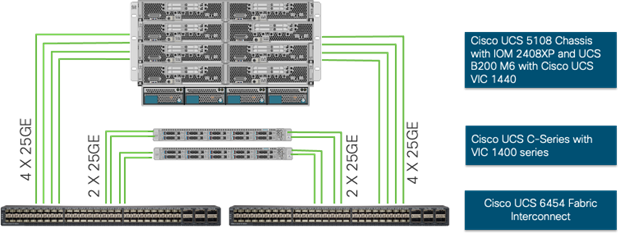
Compute System Connectivity
Cisco UCS 5108 chassis is equipped with the Cisco 2408 FEX modules. Cisco UCS 5108 chassis connects to each Cisco UCS 6454 FI using 4 x 25G ports as shown in Figure 14.
![]() If you require more bandwidth, all 8 ports on the IOMs can be connected to each FI.
If you require more bandwidth, all 8 ports on the IOMs can be connected to each FI.
Figure 14. Cisco UCSX-9508 Connectivity to Cisco UCS Fabric Interconnects
Cisco Nexus Ethernet Connectivity
The Cisco Nexus 93180YC-FX device configuration explains the core networking requirements for Layer 2 and Layer 3 communication. Some of the key NX-OS features implemented within the design are:
● Feature interface-vlan – Allows for VLAN IP interfaces to be configured within the switch as gateways.
● Feature HSRP – Allows for Hot Standby Routing Protocol configuration for high availability.
● Feature LACP – Allows for the utilization of Link Aggregation Control Protocol (802.3ad) by the port channels configured on the switch.
● Feature VPC – Virtual Port-Channel (vPC) presents the two Nexus switches as a single “logical” port channel to the connecting upstream or downstream device.
● Feature LLDP - Link Layer Discovery Protocol (LLDP), a vendor-neutral device discovery protocol, allows the discovery of both Cisco and non-Cisco devices.
● Feature NX-API – NX-API improves the accessibility of CLI by making them available outside of the switch by using HTTP/HTTPS. This feature helps with configuring the Nexus switch remotely using automation framework.
● Feature UDLD - to enable unidirectional link detection for various interfaces.
Cisco UCS Fabric Interconnect 6454 Ethernet Connectivity
Cisco UCS 6454 FIs are connected to Cisco Nexus 93180YC-FX3 switches using 25GE and 100GE connections configured as Virtual Port Channel. Each FI is connected to both Cisco Nexus switches using a 100G aggerate connection, but additional links can easily be added to the port channel to increase the bandwidth as needed. Figure 15 illustrates the physical connectivity details.
Figure 15. Cisco UCS 6454 FI Ethernet Connectivity

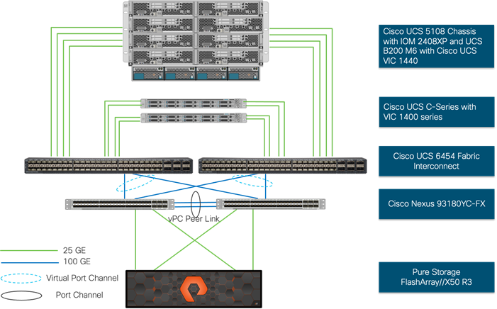
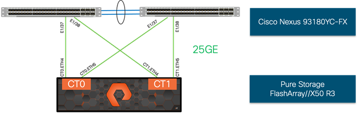
Pure Storage FlashArray//X50 R3 Ethernet Connectivity
Pure Storage FlashArray controllers are connected to Cisco Nexus 93180YC-FX3 switches using redundant 25GE connections. Figure 16 illustrates the physical connectivity details.
Figure 16. Pure Storage FlashArray//X50 R3 IP Connectivity
Cisco MDS SAN Connectivity – FC Design
The Cisco MDS 9132T is the key design component bringing together the 32Gbps Fibre Channel capabilities to the FlashStack design. Redundant 32 Gbps Fibre Channel SAN configuration is deployed utilizing two MDS 9132Ts switches. Some of the key MDS features implemented within the design are:
● Feature NPIV – N port identifier virtualization (NPIV) provides a means to assign multiple FC IDs to a single N port.
● Feature fport-channel-trunk – F-port-channel-trunks allow for the fabric logins from the NPV switch to be virtualized over the port-channel. This provides non-disruptive redundancy should individual member links fail.
● Smart-Zoning – a feature that reduces the number of TCAM entries by identifying the initiators and targets in the environment.
Cisco UCS Fabric Interconnect 6454 SAN Connectivity
For SAN connectivity, each Cisco UCS 6454 Fabric Interconnect is connected to a Cisco MDS 9132T SAN switch using 2 x 32G Fibre Channel port-channel connection as shown in Figure 17.
Figure 17. Cisco UCS 6454 FI SAN Connectivity
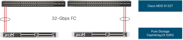
Pure FlashArray//X50 R3 SAN Connectivity
For SAN connectivity, each Pure FlashArray controller is connected to both of Cisco MDS 9132T SAN switches using 32G Fibre Channel connections as shown in Figure 18.
Figure 18. Pure FlashArray SAN Connectivity
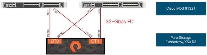
![]() Additional Pure FlashArray ports need to be connected to support fc-nvme.
Additional Pure FlashArray ports need to be connected to support fc-nvme.
VMware vSphere – ESXi Design
Multiple vNICs (and vHBAs) are created for the ESXi hosts using the Cisco UCS service profile and are then assigned to specific virtual and distributed virtual switches. The vNIC and (optional) vHBA distribution for the ESXi hosts is as follows:
● Two vNICs (one on each Fabric) for vSwitch0 to support core services such as management traffic.
● Two vNICs (one on each Fabric) for vSphere Virtual Distributed Switch (VDS) to support customer data traffic and vMotion traffic.
● One vNIC each for Fabric-A and Fabric-B for iSCSI storage access and stateless SAN boot. These vNICs are only required when iSCSI connectivity is desired.
● One vHBA each for Fabric-A and Fabric-B for FC storage access and stateless SAN boot. These vHBAs are only required when FC connectivity is desired.
![]() Typically, you will have iSCSI vNICs or the FC vHBAs configured on the ESXi servers.
Typically, you will have iSCSI vNICs or the FC vHBAs configured on the ESXi servers.
Figure 19 and Figure 20 shows the ESXi vNIC configuration in detail.
Figure 19. VMware vSphere – ESXi Host Networking for iSCSI Connectivity
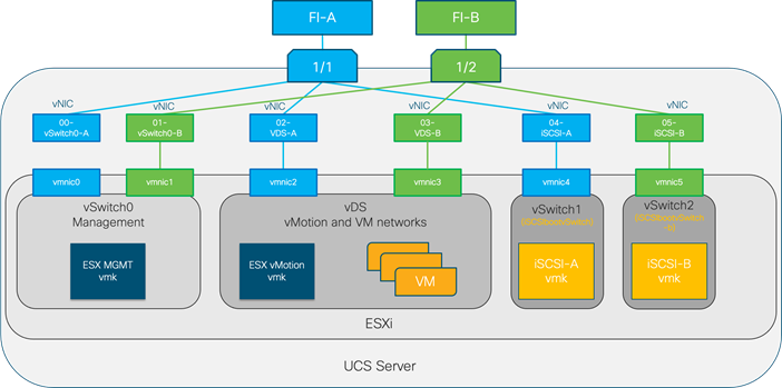
Figure 20. VMware vSphere – ESXi Host Networking for FC Connectivity
Pure Storage FlashArray - Storage Design
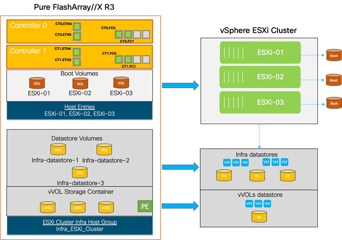
This design is implemented using VMware vSphere 7.0 U2 for the vCenter Server and ESXi version. This design leverages VMware VMFS datastores and Virtual Volumes (vVols) for storage integration.
To setup Pure Storage FlashArray, you need to configure the following items:
● Volumes
◦ ESXi boot LUNs - used to enable ESXi host boot from SAN functionality using iSCSI or FC.
◦ Infrastructure datastore(s) - used by the vSphere environment to store the VMs
● Hosts
◦ All FlashArray ESXi hosts
◦ Every active initiator for a given ESXi host should be added to the host
● Host Groups
◦ All ESXi hosts in a VMware cluster will be part of the Host Group
◦ Host Groups are used to mount Infrastructure datastores in the VMware environment
● Virtual Volumes
◦ All ESXi hosts in a VMware cluster will be part of the Host Group for vVOL access. vVOLs are connected to the VMs through protocol end points (PE) acting as subsidiary logical units (SLUs, also called sub-luns). Virtual volumes architecture and configuration is discussed in more detail in the following section.
The volumes, interfaces, and VLAN/VSAN details are shown in Figure 21.
Figure 21. Pure Storage FlashArray Volumes
Virtual Volumes Configuration
VMware Virtual Volumes (vVols), first introduced in VMware vSphere version 6.0, is a storage technology that provides policy-based, granular storage configuration and control of virtual machines (VMs). Through API-based interaction with underlying storage, VMware administrators can maintain storage configuration compliance using only native VMware interfaces.
Version 5.x of Purity//FA software introduced support for FlashArray-based vSphere Virtual Volumes (vVols). The accompanying Pure Storage Plugin for the vSphere Client (the Plugin) makes it possible to create, manage, and use vVols that are based on FlashArray volumes from within the vSphere Client.
Figure 22. High-level vSphere Virtual Volumes Architecture
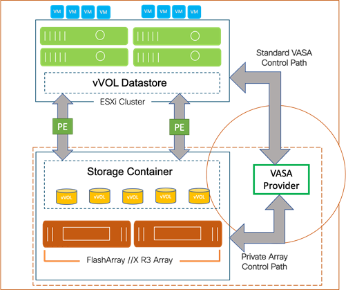
To start using vVOLs with the Pure Storage FlashArray ,the arrays Storage Providers must be registered in vCenter Server, the protocol endpoint is then connected to the hostgroup, and finally the vVol datastore is created.
Register the FlashArray Storage Providers
The two main methods to register the Storage Providers is to manually add them in vCenter Server, or to use the Pure Storage Plugin for the vSphere Client to register the storage provider for the given FlashArray. Pure Storage recommends using the plugin to register the FlashArray Storage Providers.
Connect Protocol Endpoint to Host Group(s)
Users will need to connect the protocol endpoint when manually creating the vVol Datastore in vCenter Server. This must be done via the FlashArray CLI. Should the Pure Storage Plugin be used, the plugin will automatically connect the PE to the host group that correlates to the ESXi Cluster that is used to create the vVol Datastore with the Plugin.
Mount the vVol Datastore
The vVol Datastore can be mounted manually or through the Pure Storage Plugin. When mounting the vVol Datastore, it is highly recommended to mount it to all the hosts in the ESXi cluster.
Storage Policy Based Management (SPBM)
Storage Policies can be applied to vVols VMs that can automatically configure the corresponding volumes for the VM to be protected by FlashArray protection groups. Policies can be imported from existing FlashArray protection group policies or can be created in vCenter Server to match the requirements of existing Protection Groups.
For more details on the implementation of VMware Virtual Volumes with Pure Storage FlashArray, see: https://support.purestorage.com/Solutions/VMware_Platform_Guide/003Virtual_Volumes_-_VVols/Guides_and_How_To's/Web_Guide%3A_Implementing_vSphere_Virtual_Volumes_with_FlashArray
UEFI Secure Boot
This validation of FlashStack includes using UEFI Secure Boot for the first time. Unified Extensible Firmware Interface (UEFI) is a specification that defines a software interface between an operating system and platform firmware. Cisco UCS Manager uses UEFI to replace the BIOS firmware interfaces. This allows the BIOS to run in UEFI mode while still providing legacy support. When UEFI secure boot is enabled, all executables, such as boot loaders and adapter drivers, are authenticated by the BIOS before they can be loaded. Additionally, in this validation Trusted Platform Modules (TPMs) 2.0 were installed in the Cisco UCS B200 M6 servers. VMware ESXi 7.0 supports UEFI Secure Boot. VMware vCenter 7.0 supports UEFI Secure Boot Attestation between the TPM 2.0 module and ESXi, validating that UEFI Secure Boot has properly taken place.
End-to-End FC-NVMe with FlashArray and VMware vSphere
Pure Storage FlashArray//X is the world’s first 100% native NVMe storage solution for Tier 0 and Tier 1 block storage applications.
NVM Express (NVMe) is an optimized, high-performance, scalable interface designed to work with current and the next-generation NVM technologies. The NVMe interface is defined to enable host software to communicate with nonvolatile memory over PCI Express (PCIe).
NVMe is designed to have up to 64 thousand queues. In turn, each of those queues can have up to 64 thousand commands that are processed simultaneously. This is a much larger queue depth than SCSI typically has. NVMe also streamlines the list of commands to only the basic commands that Flash technologies need.
NVMe over Fabrics (NVMe-oF) is an extension of the NVMe network protocol to Ethernet and Fibre Channel delivering faster and more efficient connectivity between storage and servers, as well as a reduction in CPU utilization of application host servers.
FC-NVMe uses the Fibre-Channel protocol as the transport. This allows data to be transferred from host memory to the Pure FlashArray target. This solution implements NVMe using the FC-NVMe protocol over a SAN built using Cisco MDS switches. NVMe initiators consisting of Cisco UCS M6 servers installed with Cisco 1400 VIC adapters can access Pure FlashArray NVMe targets over Fibre Channel.
Figure 23. End-to-End NVMe over Fibre Channel Connectivity
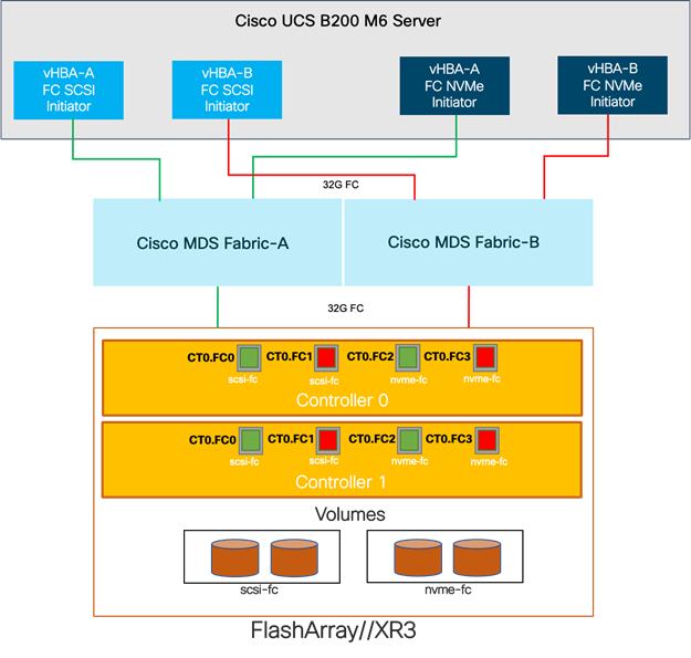
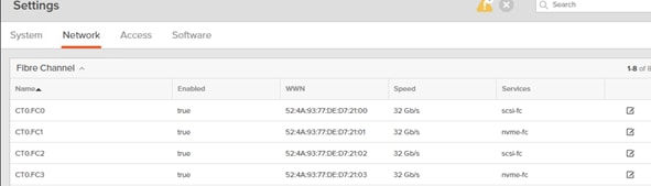
Each port on the Pure FlashArray can be configured as traditional scsi-fc port or as a nvme-fc port to support NVMe end-to-end via fibre channel from the host to storage array. Note that a given FC port is either going to be SCSI or NVMe, not both on the FlashArray.
Two ports on each Pure FlashArray controllers are configured as SCSI ports and the other two are configured as NVMe ports in this design validation as shown below.
Cisco UCS provides a unified fabric that is an architectural approach delivering flexibility, scalability, intelligence and simplicity. This flexibility allows Cisco UCS to readily support new technologies such as FC-NVMe seamlessly. In a Cisco UCS service profile, both standard Fibre Channel and FC-NVMe vHBAs can be created. The type of vHBA is selected in the Fibre Channel adapter policy as shown below.
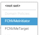
A default Fibre Channel adapter policy named FCNVMeInitiator is preconfigured in Cisco UCS Manager. This policy contains recommended adapter settings for FC-NVMe.
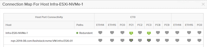
Both Fibre Channel and FC-NVMe vHBAs can exist in a Cisco UCS service profile on a single server. In the lab validation for this document, four vHBAs (one FC-NVME initiator on each Fibre Channel fabric and one Fibre Channel initiator on each Fibre Channel fabric) were created in each service profile. Each vHBA, regardless of type, was automatically assigned a worldwide node name (WWNN) and a worldwide port name (WWPN). The Cisco UCS fabric interconnects were in Fibre Channel end-host mode (NPV mode) and uplinked through a SAN port channel to the Cisco MDS 9132T switches in NPV mode. Zoning in the Cisco MDS 9132T switches connected the vHBAs to storage targets for both FC-NVMe and Fibre Channel. Single-initiator, multiple-target zones were used for both FCP and FC-NVMe.
The ESXi automatically connects to Pure FlashArray NVMe subsystem and discovers all shared NVMe storage devices that it can reach once the SAN zoning on MDS switches, and the configuration of host/host groups and volumes is completed on the Pure FlashArray.
Network Considerations
Cisco Nexus 9000 Series vPC Best Practices
The following Cisco Nexus 9000 design best practices and recommendations were used in this design.
vPC Peer Keepalive Link Considerations
● It is recommended to have a dedicated layer 3 link for vPC peer keepalive, followed by out-of-band management interface (mgmt0) and lastly, routing the peer keepalive link over an existing Layer3 infrastructure between the existing vPC peers.
● vPC peer keepalive link should not be routed over a vPC peer-link.
● The out-of-band management network is used as the vPC peer keepalive link in this design.
vPC Peer Link Considerations
● Only vPC VLANs are allowed on the vPC peer-links. For deployments that require non-vPC VLAN traffic to be exchanged between vPC peer switches, deploy a separate Layer 2 link for this traffic.
● Only required VLANs are allowed on the vPC peer links and member ports – prune all others to minimize internal resource consumption.
QoS Considerations
When using iSCSI for storage traffic, it may be necessary to prioritize the storage traffic over vMotion traffic. The deployment guide will include an example configuration, but QoS settings should always include of comprehensive plan for the individual environment.
Cisco UCS Fabric Interconnect (FI) Best Practices
The following Cisco UCS Fabric Interconnect design best practices and recommendations were used in this design.
Ethernet End-Host Mode
● This is the default switch mode for the Cisco UCS Fabric Interconnect.
● In this mode the FI will only learn MAC addresses from devices connected on Server and Appliance ports
● In this mode the FI does not run spanning-tree and handles loop avoidance using a combination of Deja-Vu check and Reverse Path Forwarding (RFP).
Storage Considerations
Boot From SAN
When utilizing Cisco UCS Server technology it is recommended to configure Boot from SAN and store the boot partitions on remote storage, this enabled architects and administrators to take full advantage of the stateless nature of service profiles for hardware flexibility across lifecycle management of server hardware generational changes, Operating Systems/Hypervisors, and overall portability of server identity. Boot from SAN also removes the need to populate local server storage creating more administrative overhead.
Pure Storage FlashArray Considerations
![]() Make sure Each FlashArray Controller is connected to BOTH storage fabrics (A/B).
Make sure Each FlashArray Controller is connected to BOTH storage fabrics (A/B).
With Purity, it’s a best practice to map Hosts to Host Groups and then Host Groups to Volumes, this ensures the Volume is presented on the same LUN ID to all hosts and allows for simplified management of ESXi Clusters across multiple nodes.
How big should a Volume be? With Purity, the complexities of aggregates, RAID groups, and so on, are removed. When managing storage, you just create a volume based on the size required, availability and performance are taken care of via RAID-HD and DirectFlash Software. As an administrator you can create 1 10TB volume or 10 1TB Volumes and their performance/availability will be the same, so instead of creating volumes for availability or performance you can think about recoverability, manageability, and administrative considerations. Such as "what data do I want to present to this application" or "what data do I want to store together so I can replicate it to another site/system/cloud…" and so on.
Port Connectivity
● 10/25/40GbE connectivity support – while both 10 and 25 Gbps is provided through 2 onboard NICs on each FlashArray controller, if additional interfaces or 40GbE connectivity are also required, then make sure additional NICs have been included in the original FlashArray BOM.
● 16/32Gb Fiber Channel support (N-2 support) – Pure Storage offers up to 32Gb FC support on the latest FlashArray//X series arrays. Always make sure the correct number of HBAs and the speed of SFPs are included in the original FlashArray BOM.
Oversubscription
To reduce the impact of an outage or maintenance scheduled downtime it Is good practice when designing fabrics to provide oversubscription of bandwidth, this enables a similar performance profile during component failure and protects workloads from being impacted by a reduced number of paths during a component failure or maintenance event. Oversubscription can be achieved by increasing the number of physically cabled connections between storage and compute. These connections can then be utilized to deliver performance and reduced latency to the underlying workloads running on the solution.
Topology
When configuring your SAN, it’s important to remember that the more hops you have, the more latency you will see. For best performance, the ideal topology is a “Flat Fabric” where the FlashArray is only one hop away from any applications being hosted on it. For iSCSI, we recommend that you do not add routing to your storage LAN.
VMware Virtual Volumes Considerations
A vCenter that is in Enhanced Linked Mode will each be able to communicate with the same FlashArray, however vCenters that are not in Enhanced Linked Mode must use CA-Signed Certificates to use the same FlashArray. Should multiple vCenters need to use the same FlashArray for vVols, they should be configured in Enhanced Linked Mode.
Ensure that the Config vVol is either part of an existing FlashArray Protection Group, Storage Policy that includes snapshots or manual snapshots of the Config vVol are taken. This will help with the VM recovery process if the VM is deleted.
Keep in mind that there are some FlashArray limits on Volume Connections per Host, Volume Count and Snapshot Count. For more details on FlashArray limits, see: https://support.purestorage.com/FlashArray/PurityFA/General_Troubleshooting/Pure_Storage_FlashArray_Limits
When a Storage Policy is applied to a vVol VM, the volumes associated with that VM are added to the designated protection group when applying the policy to the VM. Should replication be part of the policy, be mindful of the amount of VMs using that storage policy and replication group. A large amount of VMs with high change rate could cause replication to miss its schedule due to increased replication bandwidth and time needed to complete the scheduled snapshot. Pure Storage recommends vVol VMs that have Storage Policies applied be balanced between protection groups.
Pure Storage FlashArray Best Practices for VMware vSphere 7.0
The following pure storage best practices for VMware vSphere should be followed as part of a design:
● FlashArray Volumes are automatically presented to VMware vSphere using the Round Robin Path Selection Policy (PSP) and appropriate vendor Storage Array Type Plugin (SATP) for vSphere 7.0.
● vSphere 7.0 also uses the Latency SATP that was introduced in vSphere 6.7U1 (This replaces the I/O Operations Limit of 1 SATP, which was the default from vSphere 6.5U1). It is recommended to set samplingCycles - 16 and latencyEvalTime - 180000 ms.
● DataMover.HardwareAcceleratedMove, DataMover.HardwareAcceleratedInit, and VMFS3.HardwareAcceleratedLocking should all be enabled.
● When using iSCSI connected FlashArray volumes, it is recommended to set TCP DelayedAck to false (disabled) and LoginTimeout to 30 seconds. Jumbo Frames are optional when using iSCSI.
● Queue depths should be left at the default. Changing queue depths on the ESXi host is a tweak and should only be examined if a performance problem (high latency) is observed.
● Install VMware tools or Open VM tools whenever possible.
● When mounting snapshots, use the ESXi resignature option and avoid force-mounting.
● Ensure all ESXi hosts are connected to both FlashArray controllers. At a minimum at least two paths to each. Aim for total redundancy.
● Configure Host Groups on the FlashArray identically to clusters in vSphere. For example, if a cluster has four hosts in it, create a corresponding Host Group on the relevant FlashArray with exactly those four hosts—no more, no less.
● Use Paravirtual SCSI adapters for virtual machines whenever possible.
● Atomic Test and Set (ATS) is required on all Pure Storage volumes. This is a default configuration, and no changes should normally be needed.
For more details about the VMware vSphere Pure Storage FlashArray Best Practices see: https://support.purestorage.com/Solutions/VMware_Platform_Guide/User_Guides_for_VMware_Solutions/FlashArray_VMware_Best_Practices_User_Guide/Quick_Reference%3A_Best_Practice_Settings
Pure Storage FlashArray Best Practices for VMware Virtual Volumes (vVols)
Along with the above Pure Storage Best Practices for VMware vSphere the following should be considered as part of a design that includes the implementation of vVols as part of the solution:
● Create a Local FlashArray Array Admin user to register the storage provider with vs using the local “pure user’ account, vvols-admin for example.
● Use the Round Robin pathing policy (default) for the Protocol Endpoint.
● Use the Pure Storage Plugin for the vSphere Client to register the FlashArray storage provider and mount the vVols Datastore if possible.
● If manually registering the storage providers, Register both VASA providers with CT0.ETH0 and CT1.ETH0. It is supported to use ETH1 if a custom certificate is used.
● If manually mounting the vVol datastore, you will need to connect the protocol endpoint
● A single PE should be sufficient for the design utilizing the default device queue depth for the PE.
● Keep VM Templates on vVols when deploying new vVol VMs from a template.
● When resizing a VM’s VMDK that resides on a vVol complete the task from vSphere Client and not the FlashArray GUI.
● ESXi Hosts, vCenter Server and FlashArray should have the same NTP Server synchronization configuration, as well as Network port 8084 must be open and accessible from vCenter Servers and ESXi hosts to the FlashArray that will be used for vVol.
● vCenter Server should not reside on vVols.
● The FlashArray Protocol Endpoint object 'pure-protocol-endpoint' must exist. The FlashArray admin must not rename, delete or otherwise edit the default FlashArray Protocol Endpoint.
For more information on vVols best practices, see: https://support.purestorage.com/Solutions/VMware_Platform_Guide/User_Guides_for_VMware_Solutions/Virtual_Volumes_User_Guide/vVols_User_Guide%3A_Best_Practice_Summary
Test Plan
The solution was validated by deploying virtual machines running the vdbench tool. The system was validated for resiliency by failing various aspects of the system under load. Examples of the types of tests include:
● Failure and recovery of fibre channel booted ESXi hosts in a cluster
● Rebooting of fibre channel booted hosts
● Failure and recovery of redundant links to Flash Array controllers from MDS switches for Fibre Channel
● Service Profile migration between blades
● Failure of partial and complete IOM links to Fabric Interconnects
● Failure and recovery of iSCSI booted ESXi hosts in a cluster
● Rebooting of iSCSI channel booted hosts
● Failure and recovery of redundant links to Flash Array controllers from Cisco Nexus switches for iSCSI
● Failure and recovery of a Cisco Nexus switch
Validated Hardware
Table 2 lists the hardware and software versions used during solution validation. It is important to note that Cisco, Pure Storage, and VMware have compatibility matrixes that should be referenced to determine support and are available in the Appendix.
Table 2. Validated Hardware and Software
| Layer |
Device |
Image |
Comments |
| Compute |
Cisco UCS Fabric Interconnects 6400 Series, Cisco UCS B200 M6, Cisco UCS C220 M5, and Cisco UCS C125 |
4.2 (1f) |
Includes the Cisco UCS-IOM 2408, Cisco UCS Manager, Cisco UCS VIC 1440, and Cisco UCS VIC 1457/1455 |
| Network |
Cisco Nexus Switches |
9.3(7a) |
Nexus Switches |
| Cisco MDS 9132T |
8.5(1a) |
MDS Switches |
|
| Storage |
Pure FlashArray//X50 R3 |
6.1.6 |
Software version |
| Software |
Cisco UCS Manager |
4.2 |
Software version |
| VMware vSphere |
7.0 U2 |
Software version |
|
| VMware ESXi nfnic FC driver |
5.0.0.15 |
Software version |
|
| VMware ESXi nenic Ethernet driver |
1.0.35.0 |
Software version |
|
| Pure Storage Plugin |
5.0.0 |
Software version |
|
| VASA Provider |
3.5 |
Software version |
FlashStack delivers a platform for Enterprise and cloud datacenters using Cisco UCS Blade Servers, Cisco Fabric Interconnects, Cisco Nexus 9000 switches, Cisco MDS switches, and Fibre Channel or iSCSI attached Pure Storage FlashArray//X50 R3. FlashStack is designed and validated using compute, network and storage best practices for high performance, high availability, and simplicity in implementation and management.
This CVD validates the design, performance, management, scalability, and resilience that FlashStack provides to customers along with providing an automated way of deploying the solution using Ansible.
This section provides links to additional information for each partner’s solution component of this document.
Cisco UCS B-Series Servers
Cisco UCS Manager Configuration Guides
http://www.cisco.com/c/en/us/td/docs/unified_computing/ucs/release/notes/CiscoUCSManager-RN-3-1.html
Cisco UCS Virtual Interface Cards
http://www.cisco.com/c/en/us/products/interfaces-modules/ucs-virtual-interface-card-1340/index.html
Cisco Nexus Switching References
http://www.cisco.com/c/en/us/products/switches/nexus-93180YC-FX -switch/index.html
Cisco MDS 9000 Service Switch References
http://www.cisco.com/c/en/us/products/storage-networking/product-listing.html
FlashStack
VMware References
https://docs.vmware.com/en/VMware-vSphere/index.html
https://labs.vmware.com/flings/vmware-os-optimization-tool
Pure Storage Reference Documents
https://www.purestorage.com/products/flasharray-x.html
Sreenivasa Edula, Technical Marketing Engineer, UCS Data Center Solutions Engineering, Cisco Systems, Inc.
Sreeni is a Technical Marketing Engineer in the Cisco UCS Data Center Solutions Engineering team focusing on converged and hyper-converged infrastructure solutions, prior to that he worked as a Solutions Architect at EMC Corporation. He has experience in Information Systems with expertise across Cisco Data Center technology portfolio, including DC architecture design, virtualization, compute, network, storage, and cloud computing.
Joe Houghes, Senior Solutions Architect, Pure Storage, Inc.
Joe is a Senior Solutions Architect in the Portfolio Solutions team within Pure Storage, focused on solutions on the FlashStack platform along with automation and integration. He has experience from over 15 years in Information Technology across various customer and vendor organizations with architecture and operations expertise covering compute, networking, storage, virtualization, business continuity and disaster recovery, cloud computing technologies, plus automation and integration across many applications and vendor platforms.
Acknowledgements
For their support and contribution to the design, validation, and creation of this Cisco Validated Design, the authors would like to thank:
● John George, Technical Marketing Engineer, Cisco Systems, Inc.
● Haseeb Niazi, Technical Marketing Engineer, Cisco Systems, Inc.
● Craig Waters, Technical Director, Pure Storage, Inc.
● Simon Dodsley, Principal Field Solutions Architect, Pure Storage, Inc.
For comments and suggestions about this guide and related guides, join the discussion on Cisco Community at https://cs.co/en-cvds.