Cisco Data Intelligence Platform with All NVMe Storage, Cisco Intersight, and Cloudera Data Platform
Available Languages
Bias-Free Language
The documentation set for this product strives to use bias-free language. For the purposes of this documentation set, bias-free is defined as language that does not imply discrimination based on age, disability, gender, racial identity, ethnic identity, sexual orientation, socioeconomic status, and intersectionality. Exceptions may be present in the documentation due to language that is hardcoded in the user interfaces of the product software, language used based on RFP documentation, or language that is used by a referenced third-party product. Learn more about how Cisco is using Inclusive Language.
- US/Canada 800-553-2447
- Worldwide Support Phone Numbers
- All Tools
 Feedback
 Feedback

Cisco Data Intelligence Platform with All NVMe Storage, Cisco Intersight, and Cloudera Data Platform
Deployment Guide for Cisco Data Intelligence Platform with All NVMe Storage, Cisco Intersight, and Cloudera Data Platform Private Cloud Base 7.1.1
Published: September 2020

In partnership with: ![]()
About the Cisco Validated Design Program
The Cisco Validated Design (CVD) program consists of systems and solutions designed, tested, and documented to facilitate faster, more reliable, and more predictable customer deployments. For more information, go to:
http://www.cisco.com/go/designzone.
ALL DESIGNS, SPECIFICATIONS, STATEMENTS, INFORMATION, AND RECOMMENDATIONS (COLLECTIVELY, "DESIGNS") IN THIS MANUAL ARE PRESENTED "AS IS," WITH ALL FAULTS. CISCO AND ITS SUPPLIERS DISCLAIM ALL WARRANTIES, INCLUDING, WITHOUT LIMITATION, THE WARRANTY OF MERCHANTABILITY, FITNESS FOR A PARTICULAR PURPOSE AND NONINFRINGEMENT OR ARISING FROM A COURSE OF DEALING, USAGE, OR TRADE PRACTICE. IN NO EVENT SHALL CISCO OR ITS SUPPLIERS BE LIABLE FOR ANY INDIRECT, SPECIAL, CONSEQUENTIAL, OR INCIDENTAL DAMAGES, INCLUDING, WITHOUT LIMITATION, LOST PROFITS OR LOSS OR DAMAGE TO DATA ARISING OUT OF THE USE OR INABILITY TO USE THE DESIGNS, EVEN IF CISCO OR ITS SUPPLIERS HAVE BEEN ADVISED OF THE POSSIBILITY OF SUCH DAMAGES.
THE DESIGNS ARE SUBJECT TO CHANGE WITHOUT NOTICE. USERS ARE SOLELY RESPONSIBLE FOR THEIR APPLICATION OF THE DESIGNS. THE DESIGNS DO NOT CONSTITUTE THE TECHNICAL OR OTHER PROFESSIONAL ADVICE OF CISCO, ITS SUPPLIERS OR PARTNERS. USERS SHOULD CONSULT THEIR OWN TECHNICAL ADVISORS BEFORE IMPLEMENTING THE DESIGNS. RESULTS MAY VARY DEPENDING ON FACTORS NOT TESTED BY CISCO.
CCDE, CCENT, Cisco Eos, Cisco Lumin, Cisco Nexus, Cisco StadiumVision, Cisco TelePresence, Cisco WebEx, the Cisco logo, DCE, and Welcome to the Human Network are trademarks; Changing the Way We Work, Live, Play, and Learn and Cisco Store are service marks; and Access Registrar, Aironet, AsyncOS, Bringing the Meeting To You, Catalyst, CCDA, CCDP, CCIE, CCIP, CCNA, CCNP, CCSP, CCVP, Cisco, the Cisco Certified Internetwork Expert logo, Cisco IOS, Cisco Press, Cisco Systems, Cisco Systems Capital, the Cisco Systems logo, Cisco Unified Computing System (Cisco UCS), Cisco UCS B-Series Blade Servers, Cisco UCS C-Series Rack Servers, Cisco UCS S-Series Storage Servers, Cisco UCS Manager, Cisco UCS Management Software, Cisco Unified Fabric, Cisco Application Centric Infrastructure, Cisco Nexus 9000 Series, Cisco Nexus 7000 Series. Cisco Prime Data Center Network Manager, Cisco NX-OS Software, Cisco MDS Series, Cisco Unity, Collaboration Without Limitation, EtherFast, EtherSwitch, Event Center, Fast Step, Follow Me Browsing, FormShare, GigaDrive, HomeLink, Internet Quotient, IOS, iPhone, iQuick Study, LightStream, Linksys, MediaTone, MeetingPlace, MeetingPlace Chime Sound, MGX, Networkers, Networking Academy, Network Registrar, PCNow, PIX, PowerPanels, ProConnect, ScriptShare, SenderBase, SMARTnet, Spectrum Expert, StackWise, The Fastest Way to Increase Your Internet Quotient, TransPath, WebEx, and the WebEx logo are registered trademarks of Cisco Systems, Inc. and/or its affiliates in the United States and certain other countries. Lisa.
All other trademarks mentioned in this document or website are the property of their respective owners. The use of the word partner does not imply a partnership relationship between Cisco and any other company. (0809R)
© 2020 Cisco Systems, Inc. All rights reserved.
Executive Summary
In today’s environment, datasets are growing with tremendous velocity and peta bytes of data are becoming norm. For instance, customers are dealing with huge influx of machine generated data from several new use cases such as IoT, autonomous driving, smart cities, genomics, and financials, to name a few. Exponential data growth and the need to analyze the exploding volume of data at higher rate has introduced several challenges such as IO bottlenecks, several management touchpoints, growing cluster complexity, performance degradation, and so on.
Amid those challenges, surge in Artificial Intelligence/Machine Learning (AI/ML) frameworks and its tremendous adoption across various industries have led enterprises to utilize advanced computing resources i.e. CPU, GPU, and FPGA to extract key insights and gain competitive edge. Since data lakes relies heavily on I/O bandwidth, given these ongoing enhancements, feature enrichments, and convergence of other open-source frameworks around Hadoop ecosystem, it is imperative to have compute intensive workloads to operate on the same data with high-performance, hence enabling parallel processing of data in real-time.
Data scientists are constantly searching for newer techniques and methodologies that can unlock the value of big data and distill this data further to identify additional insights which could transform productivity and provide business differentiation.
Given all those challenges, in this reference architecture, Cisco Data Intelligence Platform (CDIP) is thoughtfully designed with servers that support highest IO bandwidth with the inclusion of all NVMe.
All NVMe configuration provides accelerated IO bandwidth which is essential for Hadoop performance. NVMe provides high random read-write capabilities which makes it preferred choice for NoSQL or Data Warehousing applications running on top of Hadoop and helps improve GPU utilization instead of resting idle due to slow data access and faster parallel access of large datasets. IT can now seamlessly grow to cloud scale at a smaller datacenter footprint with higher storage density and performance.
This CVD extends the portfolio of the Cisco Data Intelligence Platform solutions and taking it to the next level of innovation by providing All NVMe to the Data Lake.
Both Big Data and machine learning technology have progressed to the point where they are being implemented in production systems running 24x7. There exists a very clear need for a proven, dependable, high-performance platform for the ingestion, processing, storage, and analysis of the data, as well as the seamless dissemination of the output, results, and insights of the analysis.
This solution implements Cloudera Data Platform Private Cloud Base (CDP PvC Base) on Cisco UCS Integrated Infrastructure for Big Data and Analytics based on Cisco Data Intelligence Platform (CDIP) architecture, a world-class platform specifically designed for demanding workloads that is both easy to scale and easy to manage, even as the requirements grow to thousands of servers and petabytes of storage.
Many companies, recognizing the immense potential of big data and machine learning technology, are gearing up to leverage these new capabilities, building out departments and increasing hiring. However, these efforts face a new set of challenges:
● Making the data available to the diverse set of people who need it
● Enabling access to high-performance computing resources, GPUs, that also scale with the data growth
● Allowing people to work with the data using the environments in which they are familiar
● Publishing their results so the organization can make use of it
● Enabling the automated production of those results
● Managing the data for compliance and governance
● Scaling the system as the data grows
● Managing and administering the system in an efficient, cost-effective way
This solution is based on the Cisco UCS Integrated Infrastructure for Big Data and Analytics and includes computing, storage, connectivity, and unified management capabilities to help companies manage the immense amount of data being collected. It is built on Cisco Unified Computing System (Cisco UCS) infrastructure, using Cisco UCS C-Series Rack Servers. This architecture is specifically designed for performance and linear scalability for big data and machine learning workload.
The intended audience of this document includes sales engineers, field consultants, professional services, IT managers, partner engineering and customers who want to deploy the Cloudera Data Platform Private Cloud Base on the Cisco UCS Integrated Infrastructure for Big Data and Analytics (Cisco UCS M5 Rack-Mount servers).
This document describes the architecture, design choices, and deployment procedures for Cisco Data Intelligence Platform using Cloudera Data Platform Private Cloud Base on Cisco UCS C220 M5.
This document also serves as a step-by-step guide on how to deploy CDP PvC Base on a 16-node cluster of Cisco UCS C220 M5 Rack Server.
This solution extends the portfolio of Cisco Data Intelligence Platform (CDIP) architecture with Cloudera Data Platform Private Cloud Base, a state-of-the-art platform, providing a data cloud for demanding workloads that is easy to deploy, scale and manage. Furthermore, as the enterprise’s requirements and needs changes overtime, the platform can grow to thousands of servers, hence providing peta bytes of storage.
The following design consideration will be implemented in this validated design:
● NVMe based Cisco UCS Infrastructure for Big Data and Analytics
● Cisco Intersight deployed standalone C220 M5 Rack Server
![]() The same architecture deployed in this CVD can also be deployed with Cisco UCS Managed configuration.
The same architecture deployed in this CVD can also be deployed with Cisco UCS Managed configuration.
This CVD showcases Cisco UCS Manager (UCSM). This solution can also be deployed using Cisco Intersight. Additional Cisco UCS features will be added to the Appendix in the following months. Some of these include the following:
● Cloudera Data Platform Private Cloud
● Apache Ozone – Object Storage
● A fully integrated CDP on CDIP with
● Data lake enabled through CDP PvC Base
● AI/ML enabled through CDP Private Cloud
● Exabyte storage enabled through Apache Ozone
Cisco Data Intelligence Platform
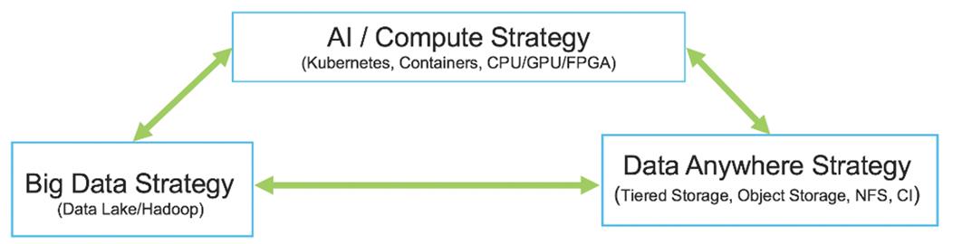
Cisco Data Intelligence Platform (CDIP) is a cloud scale architecture which brings together big data, AI/compute farm, and storage tiers to work together as a single entity while also being able to scale independently to address the IT issues in the modern data center. This architecture allows for:
● Extremely fast data ingest, and data engineering done at the data lake
● AI compute farm allowing for different types of AI frameworks and compute types (GPU, CPU, FPGA) to work on this data for further analytics
● A storage tier, allowing to gradually retire data which has been worked on to a storage dense system with a lower $/TB providing a better TCO
● Seamlessly scale the architecture to thousands of nodes with a single pane of glass management using Cisco Application Centric Infrastructure (ACI)
● Cisco Data Intelligence Platform caters to the evolving architecture bringing together a fully scalable infrastructure with centralized management and fully supported software stack (in partnership with industry leaders in the space) to each of these three independently scalable components of the architecture including data lake, AI/ML and Object stores.
Cisco has developed numerous industry leading Cisco Validated Designs (reference architectures) in the area of Big Data, compute farm with Kubernetes (CVD with RedHat OpenShift) and Object store (Scality, SwiftStack, Cloudian, and others).
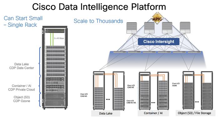
This architecture can start from a single rack and scale to thousands of nodes with a single pane of glass management with Cisco Application Centric Infrastructure (ACI).
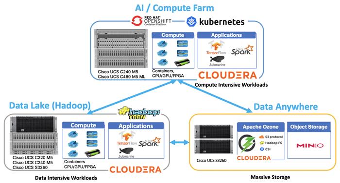
CDP on CDIP
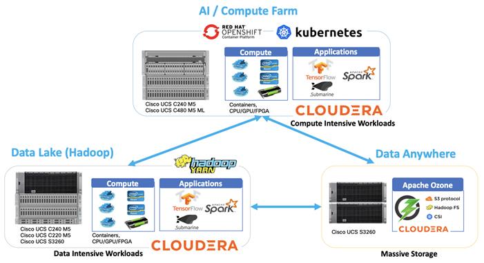
A CDIP architecture can fully be enabled by Cloudera Data Platform with the following components:
● Data lake enabled through CDP PvC Base
● AI/ML enabled through CDP Private Cloud and
● Exabyte storage enabled through Apache Ozone
Data Lake Reference Architecture
Table 1 lists the data lake reference architecture configuration details for Cisco UCS Integrated Infrastructure for Big Data and Analytics.
Table 1 Cisco UCS Integrated Infrastructure for Big Data and Analytics Configuration Options
|
|
High Performance |
Performance |
Capacity |
High Capacity |
| Servers |
16 x Cisco UCS C220 M5SN Rack Servers with small-form-factor (SFF) drives (UCSC-C220-M5SN) |
16 x Cisco UCS C240 M5 Rack Servers with small-form-factor (SFF) drives |
16 x Cisco UCS C240 M5 Rack Servers with large-form-factor (LFF) drives |
8 x Cisco UCS S3260 Storage Servers |
| CPU |
2 x 2nd Gen Intel® Xeon® Scalable Processors 6230R (2 x 26 cores, at 2.1 GHz) |
2 x 2nd Gen Intel® Xeon® Scalable Processors 5218R processors (2 x 20 cores, at 2.1 GHz) |
2 x 2nd Gen Intel Xeon Scalable Processors 5218R (2 x 20 cores, at 2.1 GHz) |
2 x 2nd Gen Intel Xeon Scalable Processors 6230R (2 x 26 cores, 2.1 GHz) |
| Memory |
12 x 32GB DDR4 (384 GB) |
12 x 32GB DDR4 (384 GB) |
12 x 32GB DDR4 (384 GB) |
12 x 32GB DDR4 (384 GB) |
| Boot |
M.2 with 2 x 240-GB SSDs |
M.2 with 2 x 240-GB SSDs |
M.2 with 2 x 240-GB SSDs |
2 x 240-GB SATA SSDs |
| Storage |
10 x 8TB 2.5in U.2 Intel P4510 NVMe High Perf. Value Endurance |
26 x 2.4TB 10K rpm SFF SAS HDDs or 12 x 1.6-TB Enterprise Value SATA SSDs |
12 x 8-TB 7.2K rpm LFF SAS HDDs |
28 x 6 TB 7.2K rpm LFF SAS HDDs per server node |
| Virtual interface card (VIC) |
25 Gigabit Ethernet (Cisco UCS VIC 1457) or 40/100 Gigabit Ethernet (Cisco UCS VIC 1497) |
25 Gigabit Ethernet (Cisco UCS VIC 1455) or 40/100 Gigabit Ethernet (Cisco UCS VIC 1497) |
25 Gigabit Ethernet (Cisco UCS VIC 1455) or 40/100 Gigabit Ethernet (Cisco UCS VIC 1497) |
40 Gigabit Ethernet (Cisco UCS VIC 1387) or 25 Gigabit Ethernet (Cisco UCS VIC 1455) or 40/100 Gigabit Ethernet (Cisco UCS VIC 1495) |
| Storage controller |
NVMe Switch included in the optimized server |
Cisco 12-Gbps SAS modular RAID controller with 4-GB flash-based write cache (FBWC) or Cisco 12-Gbps modular SAS host bus adapter (HBA) |
Cisco 12-Gbps SAS modular RAID controller with 2-GB FBWC or Cisco 12-Gbps modular SAS host bus adapter (HBA) |
Cisco 12-Gbps SAS Modular RAID Controller with 4-GB flash-based write cache (FBWC) |
| Network connectivity |
Cisco UCS 6332 Fabric Interconnect or Cisco UCS 6454/64108 Fabric Interconnect |
Cisco UCS 6332 Fabric Interconnect or Cisco UCS 6454/64108 Fabric Interconnect |
Cisco UCS 6332 Fabric Interconnect or Cisco UCS 6454/64108 Fabric Interconnect |
Cisco UCS 6332 Fabric Interconnect or Cisco UCS 6454/64108 Fabric Interconnect |
| GPU (optional) |
Up to 2 x NVIDIA Tesla T4 with 16 GB memory each |
Up to 2 x NVIDIA Tesla V100 with 32 GB memory each Or Up to 6 x NVIDIA Tesla T4 with 16 GB memory each |
2 x NVIDIA Tesla V100 with 32 GB memory each Or Up to 6 x NVIDIA Tesla T4 with 16 GB memory each |
|
As illustrated in Figure 5, a sixteen-node cluster with Rack#1 hosting sixteen Cisco UCS C220 M5 server (thirteen Data Node and three Name Node). Each link in the figure represents a 40 Gigabit Ethernet link from each of the sixteen-server connected to a pair of Cisco Nexus 9000 switch.
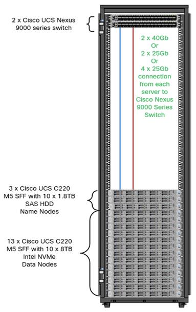
![]() The Cisco UCS VIC 1387 provides 40Gbps, Cisco UCS VIC 1457 provides 10/25Gbps, and the Cisco UCS VIC 1497 provides 40/100Gbps connectivity for the Cisco UCS C-series rack server. For more information see, Cisco UCS C-Series Servers Managing Network Adapters.
The Cisco UCS VIC 1387 provides 40Gbps, Cisco UCS VIC 1457 provides 10/25Gbps, and the Cisco UCS VIC 1497 provides 40/100Gbps connectivity for the Cisco UCS C-series rack server. For more information see, Cisco UCS C-Series Servers Managing Network Adapters.
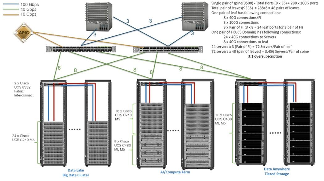
Figure 6 illustrates how to scale the solution. Each pair of Cisco UCS 6332 Fabric Interconnects has 24 Cisco UCS C240 M5 servers connected to it. This allows for eight uplinks from each Fabric Interconnect to the Cisco Nexus 9332 switch. Six pairs of 6332 FI’s can connect to a single switch with four uplink ports each. With 24 servers per FI, a total of 144 servers can be supported. Additionally, this solution can scale to thousands of nodes with the Cisco Nexus 9500 series family of switches.
In the reference architectures discussed here, each of the components is scaled separately, and for the purposes of this example, scaling is uniform. Two scale scenarios are as follows:
● Scaled architecture with 3:1 oversubscription with Cisco fabric interconnects and Cisco ACI
● Scaled architecture with 2:1 oversubscription with Cisco ACI
In the following scenarios, the goal is to populate up to a maximum of 200 leaf nodes in a Cisco ACI domain. Not all cases reach that number because they use the Cisco Nexus 9508 Switch for this sizing and not the Cisco Nexus 9516 Switch.
Scaled Architecture with 3:1 Oversubscription with Cisco Fabric Interconnects and Cisco ACI
The architecture discussed here and shown in Figure 6 supports 3:1 network oversubscription from every node to every other node across a multidomain cluster (nodes in a single domain within a pair of Cisco fabric interconnects are locally switched and not oversubscribed).
From the viewpoint of the data lake, 24 Cisco UCS C240 M5 Rack Servers are connected to a pair of Cisco UCS 6332 Fabric Interconnects (with 24 x 40-Gbps throughput). From each fabric interconnect, 8 x 40-Gbps links connect to a pair of Cisco Nexus 9336 Switches. Three pairs of fabric interconnects can connect to a single pair of Cisco Nexus 9336 Switches (8 x 40-Gbps links per Fabric Interconnect to a pair of Nexus switch). Each of these Cisco Nexus 9336 Switches connects to a pair of Cisco Nexus 9508 Cisco ACI switches with 6 x 100-Gbps uplinks (connecting to a Cisco N9K-X9736C-FX line card). the Cisco Nexus 9508 Switch with the Cisco N9K-X9736C-FX line card can support up to 36 x 100-Gbps ports, each and 8 such line cards.
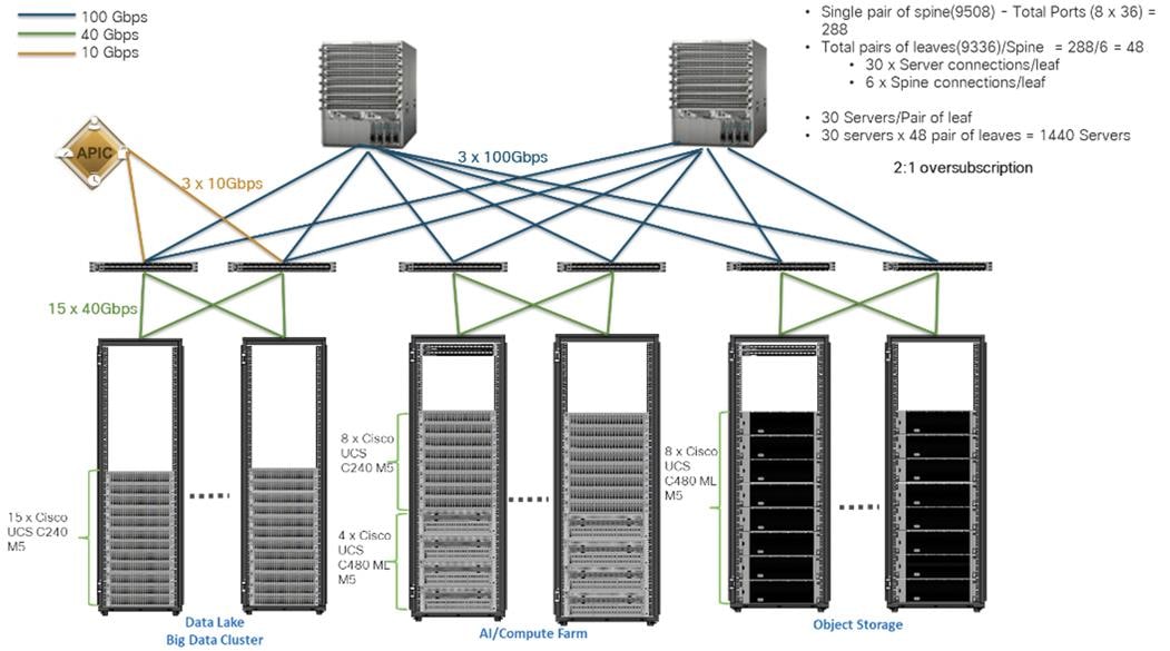
Scaled Architecture with 2:1 Oversubscription with Cisco ACI
In the scenario discussed here and shown in Figure 7, the Cisco Nexus 9508 Switch with the Cisco N9K-X9736C-FX line card can support up to 36 x 100-Gbps ports, each and 8 such line cards.
Here, for the 2:1 oversubscription, 30 Cisco UCS C240 M5 Rack Servers are connected to a pair of Cisco Nexus 9336 Switches, and each Cisco Nexus 9336 connects to a pair of Cisco Nexus 9508 Switches with three uplinks each. A pair of Cisco Nexus 9336 Switches can support 30 servers and connect to a spine with 6 x 100-Gbps links on each spine. This single pod (pair of Cisco Nexus 9336 Switches connecting to 30 Cisco UCS C240 M5 servers and 6 uplinks to each spine) can be repeated 48 times (288/6) for a given Cisco Nexus 9508 Switch and can support up to1440 servers.
To reduce the oversubscription ratio (to get 1:1 network subscription from any node to any node), you can use just 15 servers under a pair of Cisco Nexus 9336 Switches and then move to Cisco Nexus 9516 Switches (the number of leaf nodes would double).
To scale beyond this number, multiple spines can be aggregated.
Sizing the Cluster Based on Network Bandwidth
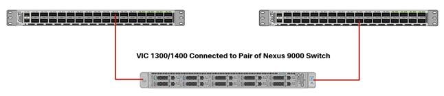
When sizing the cluster network bandwidth across multiple domains, this could impact over performance of the cluster. The following section provides a few sample calculations for active-standby and active-active connection from Cisco UCS dual port 40G VIC connected to Cisco Nexus 9000 switch achieved through a combination of switch and bonding configuration. For more information on various bonding modes and required switch configuration go to: https://access.redhat.com/documentation/en-us/red_hat_enterprise_linux/7/html/networking_guide/overview-of-bonding-modes-and-the-required-settings-on-the-switch.
Active-Standby Link Connection
Servers are configured in active-standby configuration with bonding mode 1 on OS and active links configured to one of the Nexus Switches (see Figure 1). Table 2 lists sample network bandwidth calculation for node-node communication in multi domain environment.
Table 2 Node to Node network across Domains (Active – standby)
| Server Bandwidth – Downstream (No. of Servers x Bandwidth of VIC port) |
Upstream Bandwidth (Number of ports used for uplink port-channel x Bandwidth of the Port) |
Node-Node Network Bandwidth (due to Oversubscription – Cross Domain) |
|
| 2 Domains: Oversubscription ratio 50%1 across Domain (2 racks) |
5 Domains: Oversubscription ratio 80%2 across Domain (5 racks) |
||
| 10 x 40 Gbps = 400 Gbps |
10 x 40 Gbps = 400 Gbps |
400:0.5 x 400 = 2:1 => 20 Gbps |
400:0.8 x 400 = 1.25:1 => 32 Gbps |
| 12 x 40 Gbps = 480 Gbps |
12 x 40 Gbps = 480 Gbps |
480:0.5 x 480 = 2:1 => 20 Gbps |
480:0.8 x 480 = 1.25:1 => 32 Gbps |
| 16 x 40 Gbps = 640 Gbps |
12 x 40 Gbps = 480 Gbps |
640:0.5 x 480 = 2.6:1 => 15.3 Gbps |
640:0.8 x 480 = 1.66:1 => 24.1 Gbps |
| 16 x 40 Gbps = 640 Gbps |
14 x 40 Gbps = 560 Gbps |
640:0.5 x 560 = 2.3:1 => 17.3 Gbps |
640:0.8 x 560 = 1.42:1 => 28.1 Gbps |
| 16 x 40 Gbps = 640 Gbps |
8 x 40 Gbps = 320 Gbps |
640:0.5 x 320 = 4:1 => 10 Gbps |
640:0.8 x 320 = 2.5:1 => 16 Gbps |
| 18 x 40 Gbps = 720 Gbps |
10 x 40 Gbps = 400 Gbps |
720:0.5 x 400 = 3.6:1 => 11.1 Gbps |
720:0.8 x 400 = 2.25:1 => 17.7 Gbps |
| 18 x 40 Gbps = 720 Gbps |
8 x 40 Gbps = 480 Gbps |
720:0.5 x 480 = 3:1 => 13.3 Gbps |
720:0.8 x 480 = 1.87:1 => 21.3 Gbps |
| 18 x 40 Gbps = 720 Gbps |
6 x 40 Gbps = 240 Gbps |
720:0.5 x 240 = 6:1 => 6.65 Gbps |
720:0.8 x 240 = 3.75:1 => 10.6 Gbps |
| 20 x 40 Gbps = 800 Gbps |
10 x 40 Gbps = 400 Gbps |
800:0.5 x 400 = 4:1 => 10 Gbps |
800:0.8 x 400 = 2.5:1 => 16 Gbps |
| 20 x 40 Gbps = 800 Gbps |
8 x 40 Gbps = 480 Gbps |
800:0.5 x 480 = 3.3:1 => 12.1 Gbps |
800:0.8 x 480 = 2:1 => 20 Gbps |
| 22 x 40 Gbps = 880 Gbps |
8 x 40 Gbps = 480 Gbps |
880:0.5 x 480 = 3.6:1 => 11.1 Gbps |
880:0.8 x 480 = 2.3:1 => 17.3 Gbps |
![]() 1. In a 2-rack system, 50% of traffic is expected between nodes in a Domain.
1. In a 2-rack system, 50% of traffic is expected between nodes in a Domain.
2. In a 2-rack system, 50% of traffic is expected to go across Domain.
Servers are configured in active-active configuration with bonding mode 4 on OS and active links configured to both Nexus Switches in LACP mode (see Figure 1). Table 3, Table 4, and Table 5 represents sample network bandwidth calculation for node-node communication in single domain, two rack and five rack environment respectively.
![]() The Cisco Nexus configuration and OS level configuration for Active-Active link connection is in the Appendix, section Configure Cisco Nexus and Host for Active-Active Connections.
The Cisco Nexus configuration and OS level configuration for Active-Active link connection is in the Appendix, section Configure Cisco Nexus and Host for Active-Active Connections.
Single Rack Topology
Table 3 lists a sample calculation for single rack topology.
Table 3 Node-to-Node Network Bandwidth Across Domains (Active-Active) – Single Rack Topology
| Total Bandwidth - Servers (No. of Servers1 x No. Of VICs x BW of VIC) |
Total Upstream Bandwidth supported (No. of uplink ports x No. of Switches x BW of each port) |
Upstream traffic generated by each Node for within Domain. (75%)1 |
Node– Node network bandwidth Oversubscription ratio within Domain |
| 16 x 2 x 40 Gbps = 1280 Gbps |
12 x 2 x 40 Gbps = 960 Gbps |
0.75 x 1280 = 960 Gbps |
960:960 = 1:1 => 80 Gbps |
| 16 x 2 x 40 Gbps = 1280 Gbps |
8 x 2 x 40 Gbps = 640 Gbps |
0.75 x 1280 = 960 Gbps |
960:640 = 1.5:1 => 53.3 Gbps |
| 16 x 2 x 40 Gbps = 1280 Gbps |
6 x 2 x 40 Gbps = 480 Gbps |
0.75 x 1280 = 960 Gbps |
960:480 = 2:1 => 40 Gbps |
| 18 x 2 x 40 Gbps = 1440 Gbps |
12 x 2 x 40 Gbps = 960 Gbps |
0.75 x 1440 = 1080 Gbps |
1080:960 = 1.125:1 => 71.1 Gbps |
| 18 x 2 x 40 Gbps = 1440 Gbps |
8 x 2 x 40 Gbps = 640 Gbps |
0.75 x 1440 = 1080 Gbps |
1080:640 = 1.68:1 => 47.6 Gbps |
| 18 x 2 x 40 Gbps = 1440 Gbps |
6 x 2 x 40 Gbps = 480 Gbps |
0.75 x 1440 = 1080 Gbps |
1080:480 = 2.25:1 => 35.5 Gbps |
| 20 x 2 x 40 Gbps = 1600 Gbps |
10 x 2 x 40 Gbps = 800 Gbps |
0.75 x 1600 = 1200 Gbps |
1200:800 = 1.5:1 => 53.3 Gbps |
| 20 x 2 x 40 Gbps = 1600 Gbps |
6 x 2 x 40 Gbps = 480 Gbps |
0.75 x 1600 = 1200 Gbps |
1200:480 = 2.5:1 => 32 Gbps |
| 22 x 2 x 40 Gbps = 1760 Gbps |
8 x 2 x 40 Gbps = 640 Gbps |
0.75 x 1760 = 1320 Gbps |
1320:640 = 2:1 => 40 Gbps |
| 24 x 2 x 40 Gbps = 1920 Gbps |
6 x 2 x 40 Gbps = 480 Gbps |
0.75 x 1920 = 1440 Gbps |
1440:480 = 3:1 => 26.6 Gbps |
![]() Theoretically, 50% goes across, but, considering the hashing algorithm, a much higher traffic is expected to go across and so math is calculated using 75%.
Theoretically, 50% goes across, but, considering the hashing algorithm, a much higher traffic is expected to go across and so math is calculated using 75%.
Two Rack Topology
Table 4 lists a sample calculation for 2-rack topology.
Table 4 Node to Node network across Domains (Active-Active) – 2 Rack Topology
| Per Node Network Bandwidth (If no Oversubscription) |
Within Domain traffic (%): Across Domain traffic (%) for each Server |
Upstream traffic generated by each Node for within Domain traffic |
Upstream traffic generated by each Node for across Domain traffic |
Total upstream traffic generated per Node |
|||
| 2 x 40 = 80 Gbps |
50%:50% |
0.751 x 0.5 x 80 = 30 Gbps |
0.52 x 80 = 40 Gbps |
30 + 40 = 70 Gbps |
|||
| Total upstream traffic generated by all Servers |
Total Upstream Bandwidth (Number of Uplink ports x Bandwidth) |
Oversubscription ratio |
Node to Node network Bandwidth across Domain due to Oversubscription |
||||
| 16 Servers x 70 = 1120 Gbps |
14 x 2 x 40 = 1120 Gbps |
1120:1120 = 1:1 |
80 / 1 = 80 Gbps |
||||
| 16 Servers x 70 = 1120 Gbps |
12 x 2 x 40 = 960 Gbps |
1120:960 = 1.16:1 |
80 / 1.16 = 68.9 Gbps |
||||
| 16 Servers x 70 = 1120 Gbps |
10 x 2 x 40 = 800 Gbps |
1120:800 = 1.4:1 |
80 / 1.4 = 57.1 Gbps |
||||
| 18 Servers x 70 = 1260 Gbps |
12 x 2 x 40 = 960 Gbps |
1260:960 = 1.3:1 |
80 / 1.3 = 61.5 Gbps |
||||
| 18 Servers x 70 = 1260 Gbps |
10 x 2 x 40 = 800 Gbps |
1260:800 = 1.57:1 |
80 / 1.57 = 50.9 Gbps |
||||
| 20 Servers x 70 = 1400 Gbps |
10 x 2 x 40 = 800 Gbps |
1400:800 = 1.75:1 |
80 / 1.75 = 45.7 Gbps |
||||
| 20 Servers x 70 = 1400 Gbps |
8 x 2 x 40 = 640 Gbps |
1400:640 = 2.2:1 |
80 / 2.2 = 36.3 Gbps |
||||
| 22 Servers x 70 = 1540 Gbps |
8 x 2 x 40 = 640 Gbps |
1540:640 = 2.4:1 |
80 / 2.4 = 33.33 Gbps |
||||
| 22 Servers x 70 = 1540 Gbps |
6 x 2 x 40 = 480 Gbps |
1540:480 = 3.2:1 |
80 / 3.2 = 25 Gbps |
||||
| 24 Servers x 70 = 1680 Gbps |
6 x 2 x 40 = 480 Gbps |
1680:480 = 3.5:1 |
3.5 = 22.85 Gbps |
||||
![]() 1. In a 2-rack system, 50% of traffic is expected between nodes in a Domain, and 75% of that 50% is expected to go upstream.
1. In a 2-rack system, 50% of traffic is expected between nodes in a Domain, and 75% of that 50% is expected to go upstream.
2. In a 2-rack system, 50% of traffic is expected to go across Domain.
Five Rack Topology
Table 5 lists a sample calculation for 2-rack topology.
Table 5 Node-to-Node Network Across Domains (Active-Active) – 5 Rack Topology
| Per Node Network Bandwidth (if no oversubscription) |
Within Domain Traffic (%): Across Domain Traffic (%) for Each Server |
Upstream Traffic Generated by Each Node within Domain Traffic |
Upstream Traffic Generated by Each Node for Across Domain Traffic |
Total Upstream Traffic Generated Per Node |
| 2 x 40 = 80 Gbps |
20%:80% |
0.751 x 0.2 x 80 = 12 Gbps |
0.82 x 80 = 64 Gbps |
12 + 64 = 76 Gbps |
| Total Upstream Traffic Generated by All Servers |
Total Upstream Bandwidth (Number of Uplink Ports x Bandwidth) |
Oversubscription Ratio |
Node-to-Node Bandwidth Across Domain Due to Oversubscription |
|
| 16 Servers x 76 = 1216 Gbps |
14 x 2 x 40 = 1120 Gbps |
1216:1120 = 1.08:1 |
80 / 1.08 = 74 Gbps |
|
| 16 Servers x 76 = 1216 Gbps |
12 x 2 x 40 = 960 Gbps |
1216:960 = 1.26:1 |
80 / 1.26 = 63.5 Gbps |
|
| 16 Servers x 76 = 1216 Gbps |
10 x 2 x 40 = 800 Gbps |
1216:800 = 1.52:1 |
80 / 1.52 = 52.63 Gbps |
|
| 18 Servers x 76 = 1368 Gbps |
12 x 2 x 40 = 960 Gbps |
1368:960 = 1.42:1 |
80 / 1.42 = 56.33 Gbps |
|
| 18 Servers x 76 = 1368 Gbps |
10 x 2 x 40 = 800 Gbps |
1368:800 = 1.71:1 |
80 / 1.71 = 46.78 Gbps |
|
| 20 Servers x 76 = 1520 Gbps |
10 x 2 x 40 = 800 Gbps |
1520 800 = 1.9:1 |
80 / 1.9 = 42.1 Gbps |
|
| 20 Servers x 76 = 1520 Gbps |
8 x 2 x 40 = 640 Gbps |
1520:640 = 2.37:1 |
80 / 2.37 = 33.7 Gbps |
|
| 22 Servers x 76 = 1672 Gbps |
8 x 2 x 40 = 640 Gbps |
1672:640 = 2.6:1 |
80 / 2.6 = 30.7 Gbps |
|
| 22 Servers x 76 = 1672 Gbps |
6 x 2 x 40 = 480 Gbps |
1672:480 = 3.48:1 |
80 / 3.48 = 23 Gbps |
|
| 24 Servers x 76 = 1824 Gbps |
6 x 2 x 40 = 480 Gbps |
1824:480 = 3.8:1 |
80 / 3.8 = 21 Gbps |
![]() 1. In a 5-rack system, 20% of traffic is expected between nodes in a Domain. And 75% of that 20% is expected to go upstream.
1. In a 5-rack system, 20% of traffic is expected between nodes in a Domain. And 75% of that 20% is expected to go upstream.
2. In a 5-rack system, 80% of traffic is expected to go upstream.
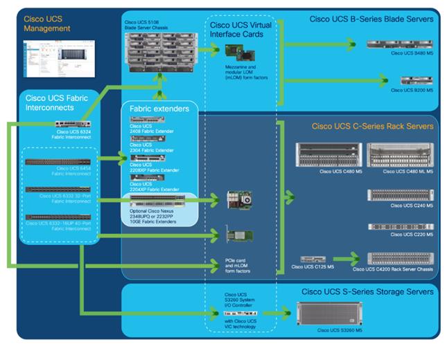
Cisco UCS Integrated Infrastructure for Big Data and Analytics
Cisco Data Intelligence Platform for Cloudera is based on Cisco UCS Integrated Infrastructure for Big Data and Analytics, a highly scalable architecture designed to meet a variety of scale-out application demands with seamless data integration and management integration capabilities built using the components described in this section.
Cisco Unified Computing System (Cisco UCS) is a next-generation data center platform that unites computing, networking, storage access, and virtualization resources into a cohesive system designed to reduce Total Cost of Ownership (TCO) and increase business agility. The system integrates a low-latency, lossless 10/25/40/100 Gigabit Ethernet unified network fabric with enterprise-class, x86-architecture servers. The system is an integrated, scalable, multi-chassis platform in which all resources participate in a unified management domain (Figure 9).
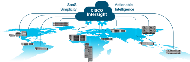
Cisco Intersight is Cisco’s systems management platform that delivers intuitive computing through cloud-powered intelligence. This platform offers a more intelligent level of management that enables IT organizations to analyze, simplify, and automate their environments in ways that were not possible with prior generations of tools. This capability empowers organizations to achieve significant savings in Total Cost of Ownership (TCO) and to deliver applications faster, so they can support new business initiatives.
Cisco Intersight is a Software as a Service (SaaS) infrastructure management which provides a single pane of glass management of CDIP infrastructure in the data center. Cisco Intersight scales easily, and frequent updates are implemented without impact to operations. Cisco Intersight Essentials enables customers to centralize configuration management through a unified policy engine, determine compliance with the Cisco UCS Hardware Compatibility List (HCL), and initiate firmware updates. Enhanced capabilities and tight integration with Cisco TAC enables more efficient support. Cisco Intersight automates uploading files to speed troubleshooting. The Intersight recommendation engine provides actionable intelligence for IT operations management. The insights are driven by expert systems and best practices from Cisco.
Cisco Intersight offers flexible deployment either as Software as a Service (SaaS) on Intersight.com or running on your premises with the Cisco Intersight virtual appliance. The virtual appliance provides users with the benefits of Cisco Intersight while allowing more flexibility for those with additional data locality and security requirements.
Cisco Intersight has the following:
● Connected TAC
● Security Advisories
● Hardware Compatibility List (HCL) and much more
To learn more about all the features of Intersight go to:
https://www.cisco.com/c/en/us/products/servers-unified-computing/intersight/index.html
To view current Intersight Infrastructure Service licensing, see
Cisco UCS C-Series Rack-Mount Servers
Cisco UCS C-Series Rack-Mount Servers keep pace with Intel Xeon processor innovation by offering the latest processors with increased processor frequency and improved security and availability features. With the increased performance provided by the Intel Xeon Scalable Family Processors, Cisco UCS C-Series servers offer an improved price-to-performance ratio. They also extend Cisco UCS innovations to an industry-standard rack-mount form factor, including a standards-based unified network fabric, Cisco VN-Link virtualization support, and Cisco Extended Memory Technology.
It is designed to operate both in standalone environments and as part of Cisco UCS managed configuration, these servers enable organizations to deploy systems incrementally—using as many or as few servers as needed—on a schedule that best meets the organization’s timing and budget. Cisco UCS C-Series servers offer investment protection through the capability to deploy them either as standalone servers or as part of Cisco UCS. One compelling reason that many organizations prefer rack-mount servers is the wide range of I/O options available in the form of PCIe adapters. Cisco UCS C-Series servers support a broad range of I/O options, including interfaces supported by Cisco and adapters from third parties.
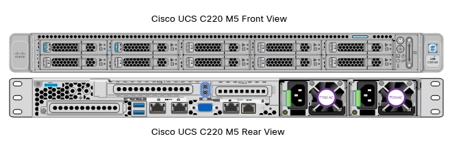
Cisco UCS C220 M5 Rack-Mount Server
The Cisco UCS C220 M5 Rack-Mount Server (Figure 11) is a 2-socket, 1-Rack-Unit (1RU) rack server offering industry-leading performance and expandability. It supports a wide range of storage and I/O-intensive infrastructure workloads, from big data and analytics to collaboration. Cisco UCS C-Series Rack Servers can be deployed as standalone servers or as part of a Cisco Unified Computing System (Cisco UCS) managed environment to take advantage of Cisco’s standards-based unified computing innovations that help reduce customers’ Total Cost of Ownership (TCO) and increase their business agility.
The latest update includes support for 2nd Generation Intel Xeon Scalable Processors, 2933-MHz DDR4 memory, and the new 512GB Intel OptaneTM DC Persistent Memory Modules (DCPMMs). With this combination of features, up to 9 TB of memory is possible (using 12 x 256 GB DDR4 DIMMs and 12 x 512 GB DCPMMs).
The Cisco UCS C220 M5 Rack-Mount Server has the following features:
● Latest Intel Xeon Scalable CPUs with up to 28 cores per socket
● Up to 24 DDR4 DIMMs for improved performance
● Up to 10 hot-swappable Small-Form-Factor (SFF) 2.5-inch drives, (up to 10 NVMe PCIe SSDs on the NVMe-optimized chassis version), or 4 Large-Form- Factor (LFF) 3.5-inch drives
● Support for 12-Gbps SAS modular RAID controller in a dedicated slot, leaving the remaining PCIe Generation 3.0 slots available for other expansion cards
● Modular LAN-On-Motherboard (mLOM) slot that can be used to install a Cisco UCS Virtual Interface Card (VIC) without consuming a PCIe slot, supporting dual 10/25/40-Gbps network connectivity
● Dual embedded Intel x550 10GBASE-T LAN-On-Motherboard (LOM) ports
● Modular M.2 or Secure Digital (SD) cards that can be used for boot
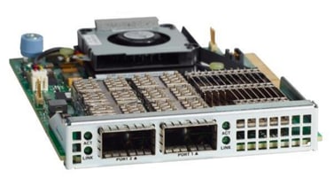
Cisco UCS Virtual Interface Cards (VICs)
Cisco UCS VIC 1387
Cisco UCS Virtual Interface Cards (VIC) are unique to Cisco. Cisco UCS Virtual Interface Cards incorporate next-generation converged network adapter (CNA) technology from Cisco and offer dual 10- and 40-Gbps ports designed for use with Cisco UCS servers. Optimized for virtualized networking, these cards deliver high performance and bandwidth utilization, and support up to 256 virtual devices.
The Cisco UCS Virtual Interface Card 1387 (Figure 12) offers dual-port Enhanced Quad Small Form-Factor Pluggable (QSFP+) 40 Gigabit Ethernet and Fiber Channel over Ethernet (FCoE) in a modular-LAN-on-motherboard (mLOM) form factor. The mLOM slot can be used to install a Cisco VIC without consuming a PCIe slot providing greater I/O expandability.
Cisco UCS VIC 1457
The Cisco UCS VIC 1457 (Figure 13) is a quad-port Small Form-Factor Pluggable (SFP28) mLOM card designed for the M5 generation of Cisco UCS C-Series Rack Servers. The card supports 10/25-Gbps Ethernet or FCoE. The card can present PCIe standards-compliant interfaces to the host, and these can be dynamically configured as either NICs or HBAs.
The Cisco VIC 1497 (Figure 14) is a dual-port Small Form-Factor (QSFP28) mLOM card designed for the M5 generation of Cisco UCS C-Series Rack Servers. The card supports 40/100-Gbps Ethernet and FCoE. The card can present PCIe standards-compliant interfaces to the host, and these can be dynamically configured as NICs and HBAs.
The Cisco Nexus 9332C is a compact form-factor 1-Rack-Unit (1RU) spine switch that supports 6.4 Tbps of bandwidth and 2.3 bpps across 32 fixed 40/100G QSFP28 ports and 2 fixed 1/10G SFP+ ports (Figure 15). Breakout cables are not supported. The last 8 ports marked in green are capable of wire-rate MACsec encryption. The switch can operate in Cisco ACI Spine or NX-OS mode.
Cisco Nexus 9300 ACI Spine Switch specifications are listed below:
● 32-port 40/100G QSFP28 ports and 2-port 1/10G SFP+ ports
● Buffer: 40MB
● System memory: 16 GB
● SSD: 128GB
● USB: 1 port
● RS-232 serial console ports: 1
● Management ports: 2 (1 x 10/100/1000BASE-T and 1 x 1-Gbps SFP)
● Broadwell-DE CPU: 4 cores

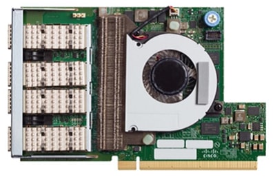
Intel P4510 Series Data Center NVMe
The Intel SSD DC P4510 Series drives built on NVMe specification 1.2 PCIe with the increased density of Intel 64-layer 3D NAND and enhanced firmware features. The 8TB DC P4510 part of the reference architecture as shown in Figure 3, is built to handle read-intensive workloads and beyond which supports optimized storage efficiency while enabling data center to do more per server and minimize service disruptions. The DC P4510 creates greater Quality of Service, bandwidth, and Performance. It significantly increases server agility and utilization and accelerates applications across a wide range of workloads to lead data centers through their evolving transformation.
Some of the key benefits are:
● Optimized for storage efficiency across a range of workloads
● Manageability to maximize IT efficiency
● Industry-leading reliability and security
● Designed for today’s modern data centers
Cloudera Data Platform Private Cloud Base (CDP PvC Base)
CDP is an integrated data platform that is easy to deploy, manage, and use. By simplifying operations, CDP reduces the time to onboard new use cases across the organization. It uses machine learning to intelligently auto scale workloads up and down for more cost-effective use of cloud infrastructure.
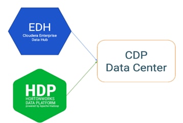
Cloudera Data Platform Private Cloud Base (CDP PvC Base) is the on-premises version of Cloudera Data Platform. This new product combines the best of both world, Cloudera Enterprise Data Hub and Hortonworks Data Platform Enterprise along with new features and enhancements across the stack. This unified distribution is a scalable and customizable platform where you can securely run many types of workloads.
Cloudera Data Platform provides:
● Unified Distribution: Whether you are coming from CDH or HDP, CDP caters both. It offers richer feature sets and bug fixes with concentrated development and higher velocity.
● Hybrid and On-prem: Hybrid and multi-cloud experience, on-prem it offers best performance, cost, and security. It is designed for data centers with optimal infrastructure.
● Management: It provides consistent management and control points for deployments.
● Consistency: Security and governance policies can be configured once and applied across all data and workloads.
● Portability: Policies stickiness with data, even if it moves across all supported infrastructure.
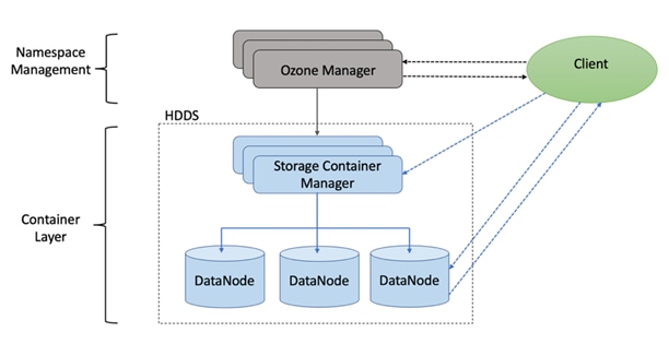
Ozone is a scalable, redundant, and distributed object store optimized for big data workloads. Apart from scaling to billions of objects of varying sizes, Ozone can function effectively in containerized environments such as Kubernetes and YARN.
Ozone consists of three important storage elements: volumes, buckets, and keys. Each key is part of a bucket, which, in turn, belongs to a volume. Only an administrator can create volumes. Depending on their requirements, users can create buckets in volumes. Ozone stores data as keys inside these buckets.
When a key is written to Ozone, the associated data is stored on the DataNodes in chunks called blocks. Therefore, each key is associated with one or more blocks. Within the DataNodes, a series of unrelated blocks is stored in a container, allowing many blocks to be managed as a single entity.
Ozone separates management of namespaces and storage, helping it to scale effectively. Ozone Manager manages the namespaces while Storage Container Manager handles the containers.
![]() Ozone is only available as a Technical Preview in Cloudera Runtime 7.1.2 and lower.
Ozone is only available as a Technical Preview in Cloudera Runtime 7.1.2 and lower.
This solution uses Red Hat Ansible Automation for all pre and post deployment steps for automating repeatable tasks to maintain consistency.
Red Hat Ansible Automation is a powerful IT automation tool. It is capable of provisioning numerous types of resources and deploying applications. It can configure and manage devices and operating system components. Due to its simplicity, extensibility, and portability, this solution extensively utilizes Ansible for performing repetitive deployment steps across the nodes.
![]() For more information about Ansible, go to: https://www.redhat.com/en/technologies/management/ansible
For more information about Ansible, go to: https://www.redhat.com/en/technologies/management/ansible
The cluster configuration consists of the following:
● 16 Cisco UCS C220 M5 Rack-Mount servers
● 2 Cisco UCS Nexus 9000 series switch
● 1 Cisco R42610 standard racks
● 2 Vertical Power distribution units (PDUs) (Country Specific)
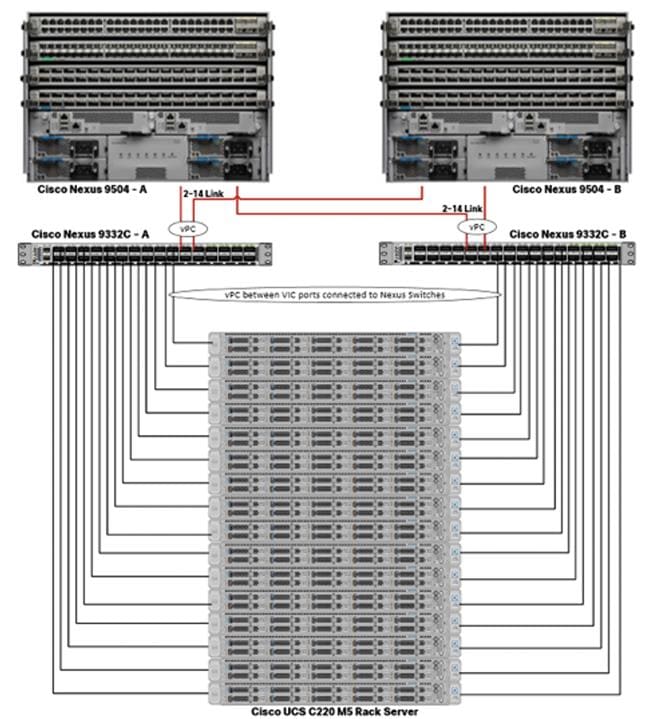
Single rack consists of two vertical PDUs and two Cisco UCS Nexus 9000 series switch with sixteen Cisco UCS C220 M5 Rack Servers connected to each of the vertical PDUs for redundancy; thereby, ensuring availability during power source failure. Figure 18 represents a 40 Gigabit Ethernet link from each server is connected to both Fabric Interconnects
![]() Please contact your Cisco representative for country-specific information.
Please contact your Cisco representative for country-specific information.
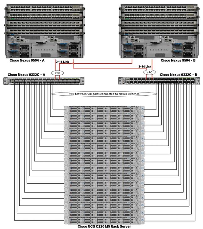
![]() Cisco UCS VIC ports connected to each Nexus switch in active-standby configuration with active links configured on switch A with pinning recovery to switch A in case of link failure in RHEL OS bond configuration to keep traffic locally on leaf switch.
Cisco UCS VIC ports connected to each Nexus switch in active-standby configuration with active links configured on switch A with pinning recovery to switch A in case of link failure in RHEL OS bond configuration to keep traffic locally on leaf switch.
![]() Virtual port-channel to Northbound/Spine switch consumes only cross domain traffic meaning server to server communication which are connected to two separate pair of leaf switch.
Virtual port-channel to Northbound/Spine switch consumes only cross domain traffic meaning server to server communication which are connected to two separate pair of leaf switch.
![]() The same architecture can be implemented with Active/Active LACP (mode 4) or balanced-alb (mode 6) based configuration. A pair of Cisco Nexus switch (A/B) are configured with vPC domain and vPC peer-link with LACP configuration as per the Cisco Nexus switch configuration best practice.
The same architecture can be implemented with Active/Active LACP (mode 4) or balanced-alb (mode 6) based configuration. A pair of Cisco Nexus switch (A/B) are configured with vPC domain and vPC peer-link with LACP configuration as per the Cisco Nexus switch configuration best practice.
Port Configuration on Cisco Nexus 9332C
Table 6 lists the port configuration on Cisco UCS Nexus 9000 series switch.
Table 6 Port Configuration on Cisco UCS Nexus Switch
| Port Type |
Port Number |
| Network Uplink from Cisco UCS C220 M5 to Nexus 9332C Switch |
9-24 |
Server Configuration and Cabling for Cisco UCS C220 M5
The Cisco UCS C220 M5 Rack Server is equipped with 2 x 2nd Gen Intel Xeon Scalable Family Processor 6230R (2 x 26 cores, 2.1 GHz), 384 GB of memory (12 x 32GB @ 2933MHz), Cisco UCS Virtual Interface Card 1387, 10 x 8TB 2.5in U.2 Intel P4510 NVMe High Perf. Value Endurance, M.2 with 2 x 240-GB SSDs for Boot.
Figure 19 illustrates the port connectivity between the Cisco UCS Nexus switch and Cisco UCS C220 M5 Rack Server. Sixteen Cisco UCS C220 M5 servers are installed in this configuration.
For information on physical connectivity and single-wire management, go to: https://www.cisco.com/c/en/us/td/docs/unified_computing/ucs/c-series_integration/ucsm4-0/b_C-Series-Integration_UCSM4-0/b_C-Series-Integration_UCSM4-0_chapter_01.html
![]() With Cisco UCS VIC 1455 and 1457, by default a port-channel is turned on between port 1-2 and port-channel between port 3-4. Up to 14 additional vHBAs or vNICs can be created.
With Cisco UCS VIC 1455 and 1457, by default a port-channel is turned on between port 1-2 and port-channel between port 3-4. Up to 14 additional vHBAs or vNICs can be created.
![]() When port-channel mode is set to enabled, the ports on the Cisco Nexus switch should be configured as channel group members.
When port-channel mode is set to enabled, the ports on the Cisco Nexus switch should be configured as channel group members.
![]() The Cisco UCS 1455 and 1457 Virtual Interface Cards, in non-port channel mode, provide four vHBAs and four vNICs by default. Up to 10 additional vHBAs or vNICs can be created.
The Cisco UCS 1455 and 1457 Virtual Interface Cards, in non-port channel mode, provide four vHBAs and four vNICs by default. Up to 10 additional vHBAs or vNICs can be created.
![]() As a best practice, select port 1 and 3 to connect to a pair of Cisco Nexus switch, port 2 and 4 can be added without the need for any additional changes if desired.
As a best practice, select port 1 and 3 to connect to a pair of Cisco Nexus switch, port 2 and 4 can be added without the need for any additional changes if desired.
![]() Switching between port-channel mode on/off requires server reboot.
Switching between port-channel mode on/off requires server reboot.
![]() For detailed configuration through Intersight see https://www.intersight.com/help/resources/creating_network_policies
For detailed configuration through Intersight see https://www.intersight.com/help/resources/creating_network_policies
Software Distributions and Firmware Versions
The software distributions required versions are listed in Table 7.
Table 7 Software Distribution and Version
| Layer |
Component |
Version or Release |
| Compute |
Cisco UCS C220 M5 |
4.1(1f) |
| Network |
Cisco UCS VIC1387 Firmware |
4.4(1c) |
| Storage |
PCIe-Switch |
1.8.0.58-22d9 |
| Software |
Red Hat Enterprise Linux Server |
7.7 |
| Cisco Integrated Management Controller (CIMC) |
4.1(1f) |
|
| Cloudera CDP PvC Base |
7.1.1 |
|
| Hadoop |
3.1 |
|
| Spark |
2.4 |
![]() The latest drivers can be downloaded here: https://software.cisco.com/download/home/283862063/type/283853158/release/4.0(4)
The latest drivers can be downloaded here: https://software.cisco.com/download/home/283862063/type/283853158/release/4.0(4)
Cisco Intersight provides the following features for ease of operations and administrator to the IT staff.
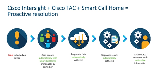
Connected TAC is an automated transmission of technical support files to the Cisco Technical Assistance Center (TAC) for accelerated troubleshooting.
Cisco Intersight enables Cisco TAC to automatically generate and upload Tech Support Diagnostic files when a Service Request is opened. If you have devices that are connected to Intersight but not claimed, Cisco TAC can only check the connection status and will not be permitted to generate Tech Support files. When enabled, this feature works in conjunction with the Smart Call Home service and with an appropriate service contract. Devices that are configured with Smart Call Home and claimed in Intersight can use Smart Call Home to open a Service Request and have Intersight collect Tech Support diagnostic files.
To enable Connected TAC, follow these steps:
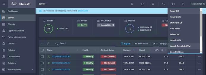
1. Log into Intersight.com
2. Click the Servers tab. Select Server > Actions tab. From the drop-down list, click Open TAC Case.
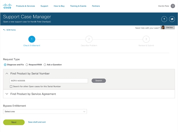
3. Clicking “Open TAC Case” launches Cisco URL for Support case manager where associated service contracts for Server or Fabric Interconnect is displayed.
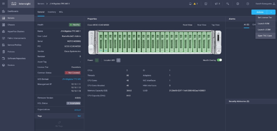
4. Click Continue.
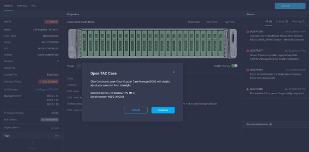
5. Follow the procedure to Open TAC Case.
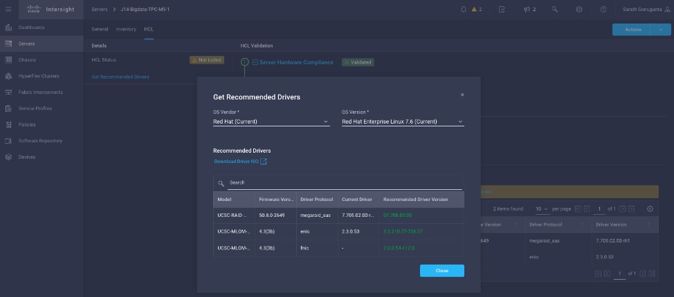
Cisco Intersight Integration for HCL
Cisco Intersight evaluates the compatibility of your Cisco UCS and Cisco HyperFlex systems to check if the hardware and software have been tested and validated by Cisco or Cisco partners. Cisco Intersight reports validation issues after checking the compatibility of the server model, processor, firmware, adapters, operating system, and drivers, and displays the compliance status with the Hardware Compatibility List (HCL).
You can use Cisco UCS Tools, a host utility vSphere Installation Bundle (VIB), or OS Discovery Tool, an open source script to collect OS and driver information to evaluate HCL compliance.
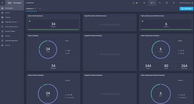
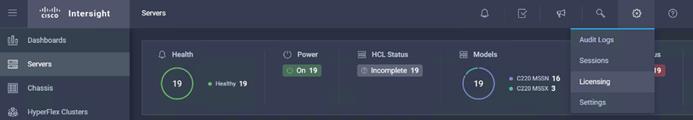
In Intersight, you can view the HCL compliance status in the dashboard (as a widget), the Servers table view, and the Server details page.
![]() For more information, go to: https://www.intersight.com/help/features#compliance_with_hardware_compatibility_list_(hcl)
For more information, go to: https://www.intersight.com/help/features#compliance_with_hardware_compatibility_list_(hcl)
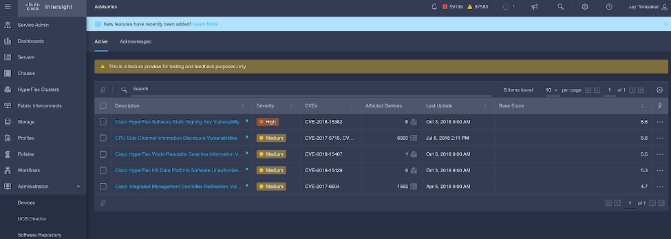
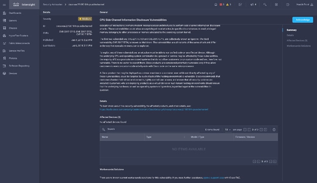
Cisco Intersight sources critical security advisories from the Cisco Security Advisory service to alert users about the endpoint devices that are impacted by the advisories and deferrals. These alerts are displayed as Advisories in Intersight. The Cisco Security Advisory service identifies and monitors and updates the status of the advisories to provide the latest information on the impacted devices, the severity of the advisory, the impacted products, and any available workarounds. If there are no known workarounds, you can open a support case with Cisco TAC for further assistance. A select list of the security advisories is shown in Intersight under Advisories.
![]()
Deployment Hardware and Software
This section details the Cisco UCS C220 M5 Rack Servers with Cisco Intersight and Cisco Nexus 9000 switch configuration that was done as part of the infrastructure build out. The racking, power, and installation of the Cisco UCS Rack Server is described in the physical topology section earlier in this document. Please refer to the Cisco Integrated Management Controller Configuration Guide for more information about each step.
Configure Cisco Nexus 9000 Switch for a Cluster Setup
To configure the Cisco Nexus 9000 switch, follow this step:
1. Verify the following physical connections to Cisco Nexus 9332C:
a. The management Ethernet port (mgmt0) is connected to an external hub, switch, or router.
b. The Ethernet ports 1/1 through 1/6 and 1/27 through 1/32 on both Nexus are directly connected to ToR switch.
c. The Ethernet ports 1/9 through 1/24 on both Nexus are directly connected to VIC interfaces of Data nodes.
To configure Nexus A, follow these steps:
1. Cisco UCS C220 M5 server VIC interface connected to each Nexus switch. Port 9-24 is configured. Configure the ethernet interfaces on both Nexus switches.
# interface Ethernet1/9
# description Connected to Server rhel01
# switchport access vlan 14
# mtu 9216
# interface Ethernet1/10
# description Connected to Server rhel02
# switchport access vlan 14
# mtu 9216
2. Cisco Nexus 9332C ports 1 through 6 and 27 through 32 connected to upstream switch. Configure ethernet interfaces on both Cisco Nexus switch connected to upstream switch.
interface port-channel50
description NB_ToR_N9K
switchport mode trunk
switchport trunk allowed vlan 14
spanning-tree port type network
mtu 9216
interface Ethernet1/27
description K14-N9K-P19-24
switchport mode trunk
switchport trunk allowed vlan 14
spanning-tree port type network
mtu 9216
channel-group 50 mode active
interface Ethernet1/28
description K14-N9K-P19-24
switchport mode trunk
switchport trunk allowed vlan 14
spanning-tree port type network
mtu 9216
channel-group 50 mode active
For more information about configuring Cisco Nexus 9000 Series, go to:
![]() Go to the Appendix to configure active-active (balance-alb/mod 6 or 802.3ad/mod 4) based deployment.
Go to the Appendix to configure active-active (balance-alb/mod 6 or 802.3ad/mod 4) based deployment.
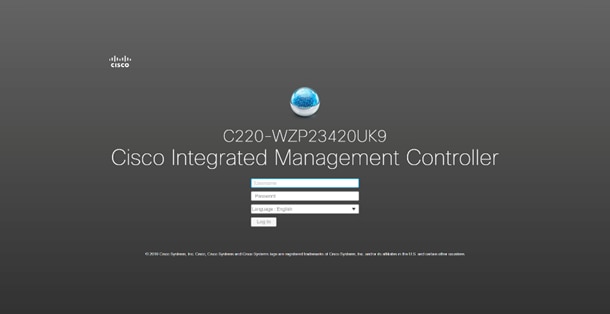
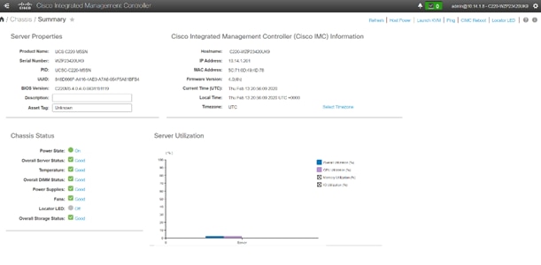
Configure Cisco Integrated Management Controller
To configure the on-board Cisco IMC, first connect a KVM console to the server, and follow these steps:
1. In the BIOS POST screen, press F8 to display the CIMC configuration screen.
2. A prompt displays to enter the default password and provide the user password (only first time).
3. Select Dedicated NIC mode.
4. Select Static or DHCP assignment.
5. For Static mode, configure the IP address, Netmask and Gateway for the IPv4 setting of the CIMC.
6. Select None for NIC redundancy.
7. Press F10 to save the configuration and exit the utility.
8. Open a web browser on a computer on the same network.
9. Enter the IMC IP address of the Cisco UCS C220 M5 Server: http://<<var_cimc_ip_address>.
10. Enter the login credentials as updated in the IMC configuration.
Cisco Intersight and IMC Configuration
This section details the Cisco Intersight configuration and Cisco IMC (Integrated Management Controller) configuration that was done as part of the infrastructure build out. The racking, power, and installation of the Cisco UCS Rack Server is described in the physical topology section earlier in this document.
Integrate Cisco IMC with Intersight
To register Cisco IMC to Intersight, follow these steps:
1. From the Cisco IMC, go to Admin > Device connector.
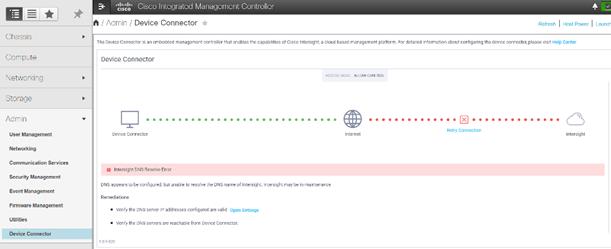
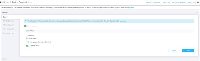
2. On the right side of the screen, click Settings.
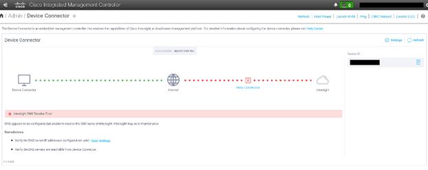
3. In the Settings screen, go to the General tab and enable the “Device connector.” For the Access Mode, select “Allow control” and enable “Tunneled vKVM.”
![]() Tunneled vKVM is supported only for Cisco UCS C-Series servers with an Advantage or Premier license.
Tunneled vKVM is supported only for Cisco UCS C-Series servers with an Advantage or Premier license.
![]() We enabled and launched Tunneled vKVM to complete OS Installation from Cisco Intersight.
We enabled and launched Tunneled vKVM to complete OS Installation from Cisco Intersight.
4. Configure DNS, NTP, Proxy as required for reachability to Intersight.
5. Verify reachability to Cisco Intersight is updated after configuring Settings.
6. Log into Cisco Intersight with your credentials.

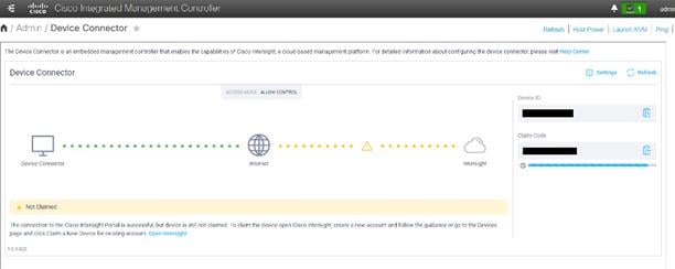
7. Click Continue to create a new Account or new devices can be registered in existing account. We created a new Account.

8. Provide Device ID and Claim code to create an account for the cluster.
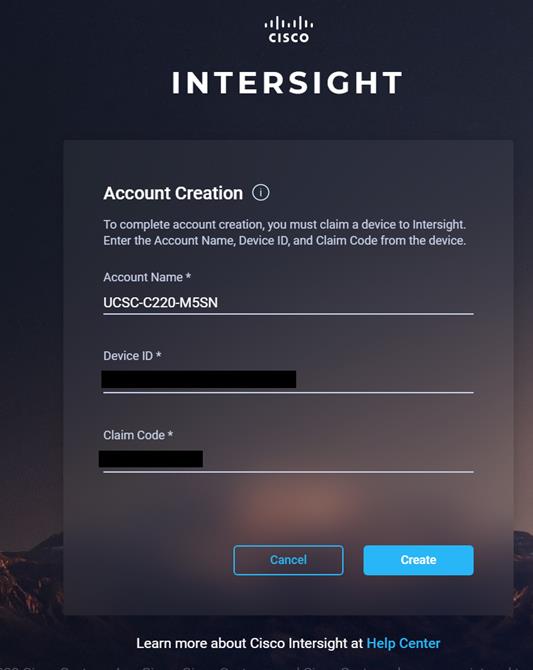
9. Verify the account is created successfully.

10. After logging in, verify the device added is listed under Administration > Devices.
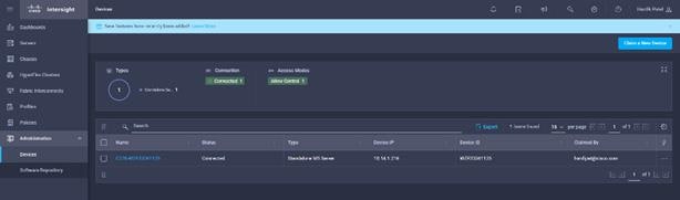
11. Click Claim a New Device to claim all remaining servers.
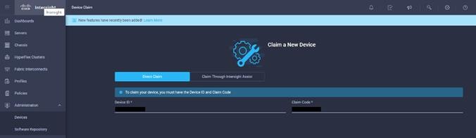
12. Make sure all servers are claimed (the servers that are part of the cluster configuration).
13. Click Settings, then select Licensing.
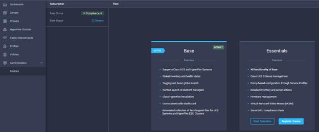
14. Click Register License to assign Essential, Advanced. or Premier License for Cisco Intersight. For more information about the different license tiers for Cisco Intersight, see: https://www.intersight.com/help/getting_started#licensing_requirements
By default, the claimed devices in Cisco Intersight are allocated Base License Tier.
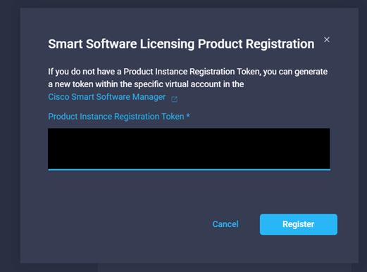
15. Enter Product Registration Token for Cisco Intersight. Click Register.
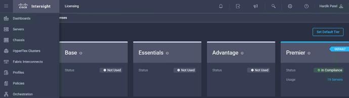
16. Click Set Default Tier. Assign the desired Default Tier.
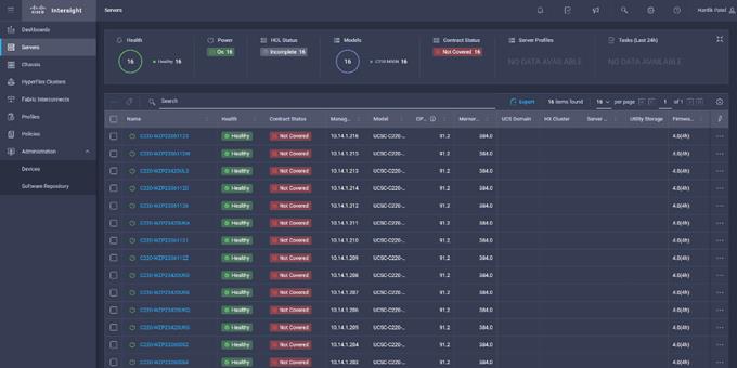
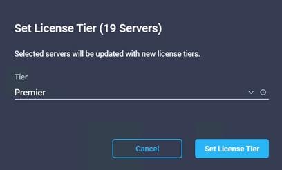
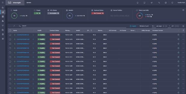
17. To assign a new license tier to existing server, click the Servers tab in Cisco Intersight. Select the server(s). Select Set License Tier.
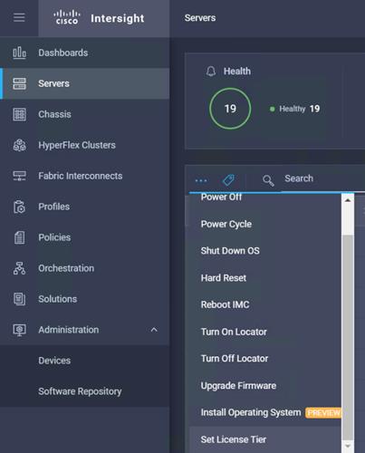
18. Select License Tier from the drop-down list.
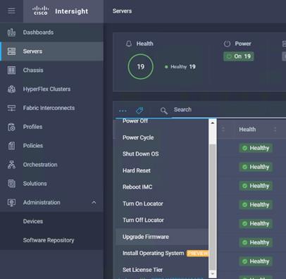
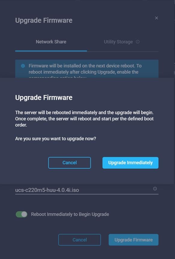
19. From the Servers tab, check the checkbox to select all servers. Click the ellipses to view the drop-down list. Click Upgrade firmware.
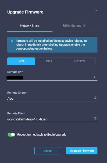
20. Clicking the firmware upgrade provides the option to choose the location of the firmware iso. We configured the NFS share for remote ISO repository. Provide the information for Remote IP, Remote Share and Remote File. Click Upgrade Firmware.
![]() The storage utility-based firmware upgrade steps are described in the Appendix.
The storage utility-based firmware upgrade steps are described in the Appendix.
21. Click Upgrade Immediately.
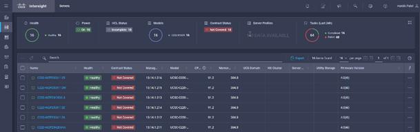
22. The progress indicator is displayed next to the server being upgraded in the Servers menu.
23. Click an individual server to display the status of the update.
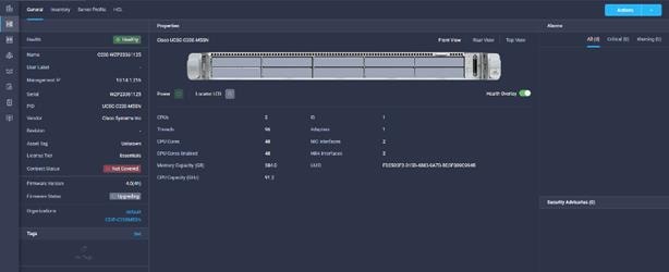
24. The updated version can be verified from the Servers tab.
![]() More information about the firmware upgrade can be found here: https://intersight.com/help/features#firmware_upgrade
More information about the firmware upgrade can be found here: https://intersight.com/help/features#firmware_upgrade
Configure Policies to Create Server Profile
To create policies for Server Profiles creation, follow these steps. These steps can also be completed at the time of the Server Profile creation.
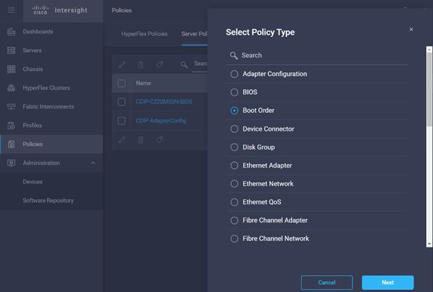
1. On Cisco Intersight WebUI, select the Policies tab. Click Create Server Policy. Create Server Policy provides an option to create different policies.
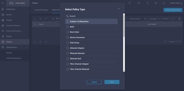
2. Select Adapter Configuration from the list of policies, then click Next.
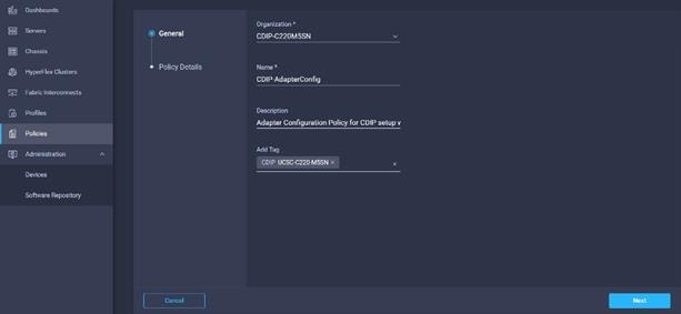
3. Enter the Organization, Name, Description and create a new tag or assign an existing tag. Click Next.
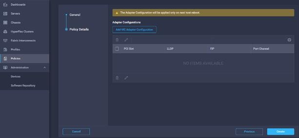
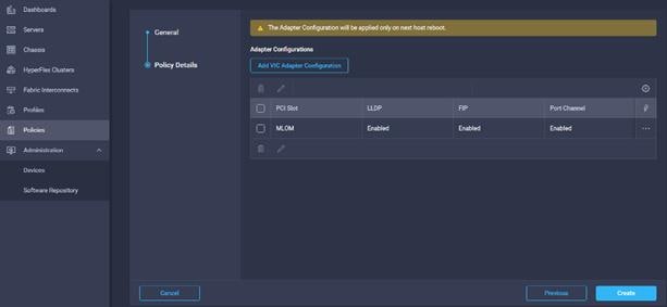
4. Click Add VIC Adapter Configuration.
5. Select PCI Slot and required setting for the Adapter Configuration.
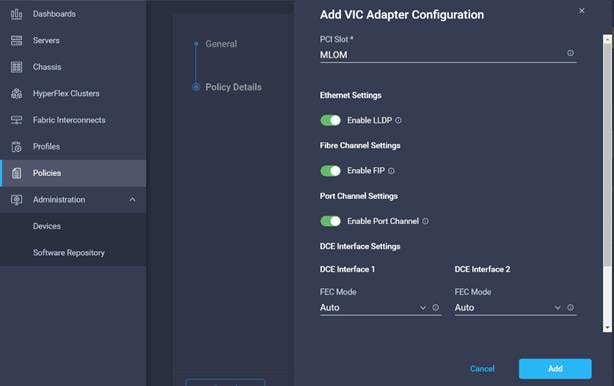
6. Click Create.
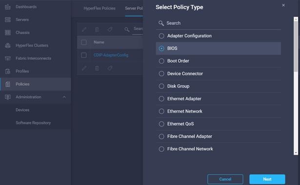
7. Select BIOS configuration in Create Server Policy options.
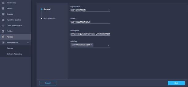
8. Enter the Organization, Name, Description and create a new tag or assign an existing tag. Click Next.
9. Configure the BIOS policy.
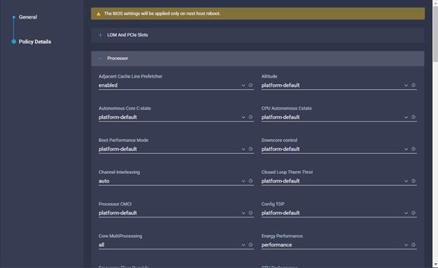
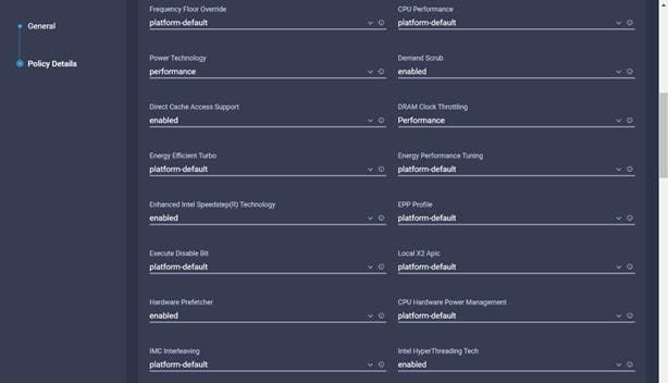
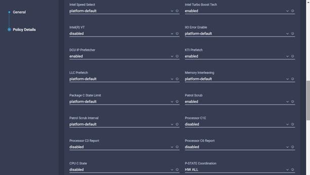
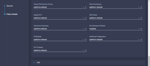
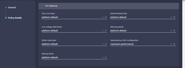
![]() Cisco recommends that you upgrade to Cisco UCS Manager Release 4.0(4h) or Release 4.1(1c) or later to expand memory fault coverage. ADDDC Sparing will be enabled and configured as "Platform Default" for Memory RAS configuration. For more information, refer to Performance Tuning Guide for Cisco UCS M5 Servers.
Cisco recommends that you upgrade to Cisco UCS Manager Release 4.0(4h) or Release 4.1(1c) or later to expand memory fault coverage. ADDDC Sparing will be enabled and configured as "Platform Default" for Memory RAS configuration. For more information, refer to Performance Tuning Guide for Cisco UCS M5 Servers.
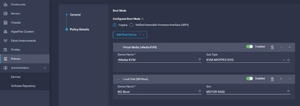
10. Select Boot order in Create Server Profile.

11. Enter the Organization, Name, Description and create a new tag or assign an existing tag. Click Next.
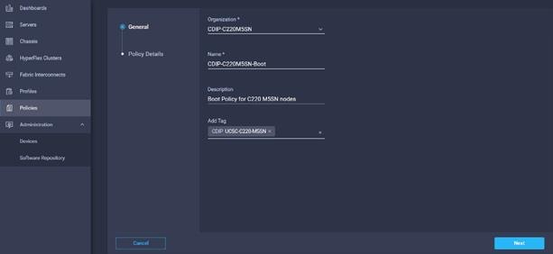
12. Select the boot mode.
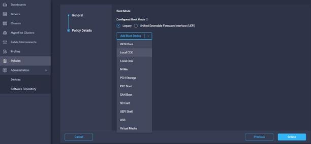
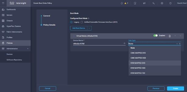
13. From the list of Boot Device select Virtual Media (vMedia-KVM) and select KVM mapped DVD as Sub-Type.
14. From the Add Boot Device list, select Local Disk and enter the name for the device and slot as MSTOR-RAID for M2 boot drives.

15. Select Boot order in Create Server Profile.
16. Enter the Organization, Name, Description and create a new tag or assign an existing tag. Click Next.
17. Select the boot mode.

18. From the list of Boot Device select Virtual Media (vMedia-KVM) and select KVM mapped DVD as Sub-Type.

19. From the Add Boot Device list, select Local Disk and enter the name for the device and slot as MSTOR-RAID for M2 boot drives.
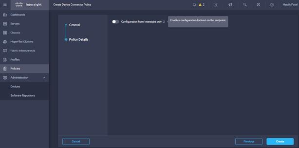
20. Enable the option “Configuration from Intersight only” if you want to control only from Intersight.
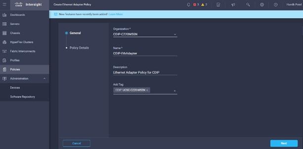
21. Create Ethernet Adapter Policy in Create Server Policy.

22. Enter the Organization, Name, Description and create a new tag or assign an existing tag. Click Next.
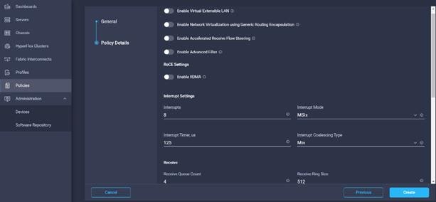
23. Leave the default settings or set the custom value and click Create. For more information, see: Tuning Guidelines for Cisco UCS Virtual Interface Cards.
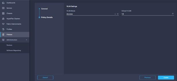
24. Create Ethernet Network Policy in Create Server Policy.

25. Enter the Organization, Name, Description and create a new tag or assign an existing tag. Click Next.
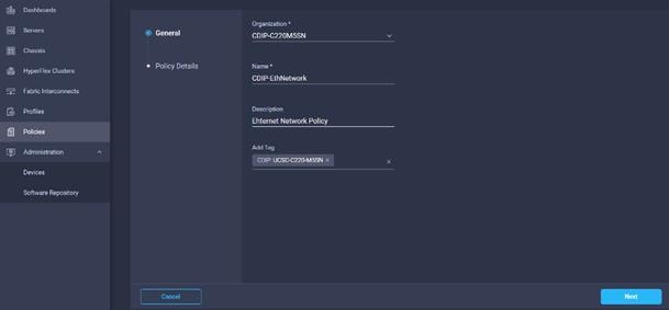
26. Select VLAN mode and Default VLAN. Click Create.
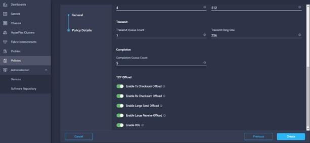
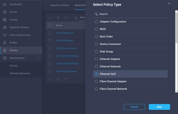
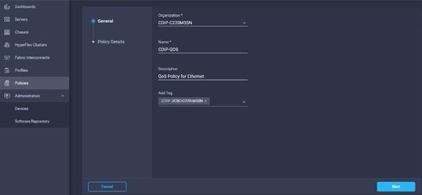
27. Create Ethernet QoS Policy in Create Server Policy.
28. Enter Organization, Name, Description and create a new tag or assign an existing tag. Click Next.
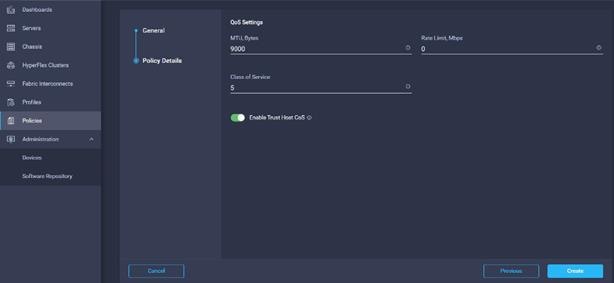
29. Select MTU 9000, Class of Service (CoS). Enable Trust Host CoS.
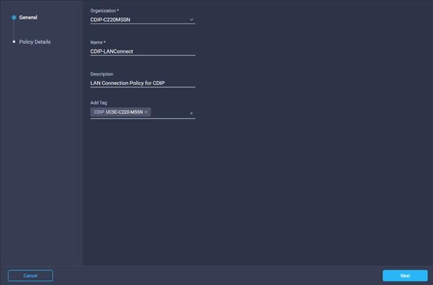
30. Create LAN Connectivity Policy in Create Server Policy.
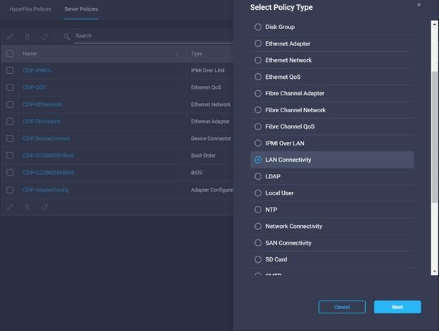
31. Enter the Organization, Name, Description and create a new tag or assign an existing tag. Click Next.
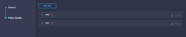
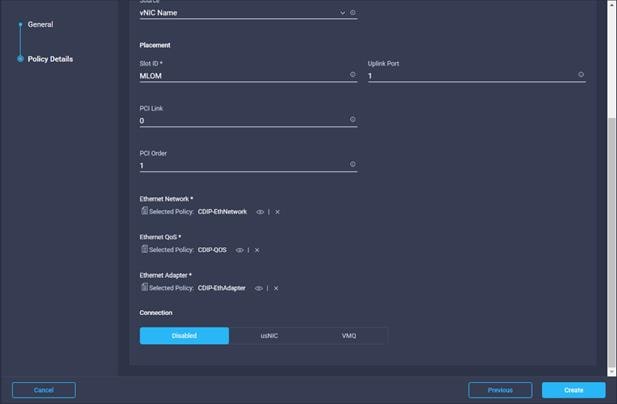
32. Add vNICs required and provide vNIC configuration details.
![]() The following steps are for the Cisco VIC 1387. For more information, go to the Cisco Intersight section Creating Network Policies. For Cisco VIC 1400 series with four ports, the PCI order will be changed to 1 and 3 or 1,2,3 and 4 depends on how many ports are in use and whether port-channel mode is enabled/disabled.
The following steps are for the Cisco VIC 1387. For more information, go to the Cisco Intersight section Creating Network Policies. For Cisco VIC 1400 series with four ports, the PCI order will be changed to 1 and 3 or 1,2,3 and 4 depends on how many ports are in use and whether port-channel mode is enabled/disabled.
33. Provide input for eth0 as shown in the screenshot below for MLOM:
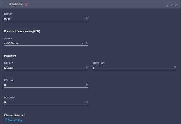
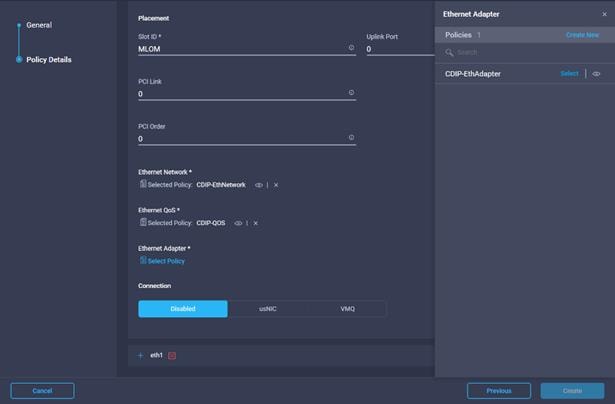
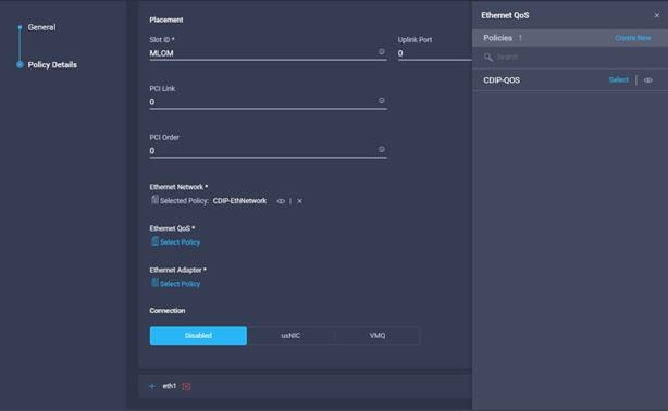
34. Select the previously created Ethernet Network, Ethernet QoS, and Ethernet Adapter Policy.

35. Repeat steps 32-33 for eth1.
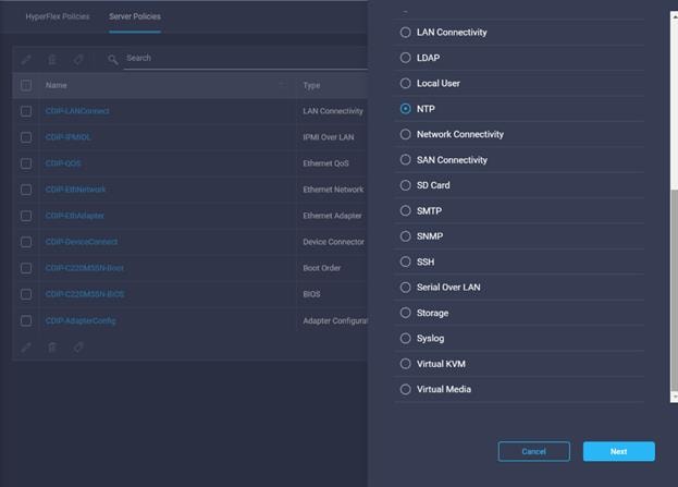
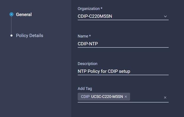
36. Select NTP in Create Server Policy.

37. Enter the Organization, Name, Description and create a new tag or assign an existing tag. Click Next.
38. Enable NTP server then Add NTP server.

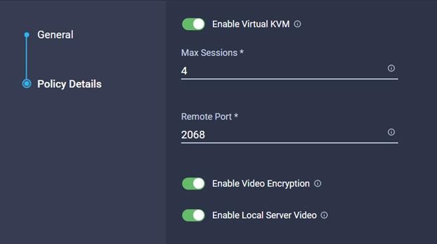
39. Create Virtual KVM policy in Create Server Policy.
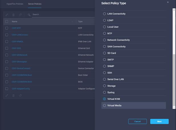
40. Enter the Organization, Name, Description and create a new tag or assign an existing tag. Click Next.

41. Configure the information related to the number of sessions and remote port.
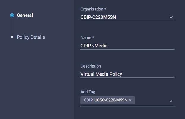
42. Select Virtual Media in Create Server Policy.
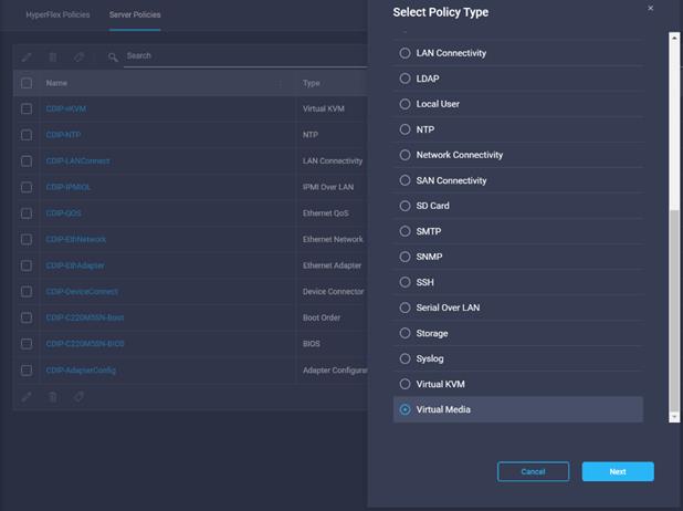
43. Enter the Organization, Name, Description and create a new tag or assign an existing tag. Click Next.
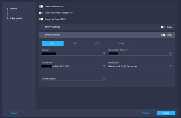
44. Enable Virtual Media, then enable either HDD or CDD Virtual Media. Select NFS/CIFS/HTTP/HTTPS. Enter input to access ISO image to install OS from.
45. Repeat steps 32-33 for eth1.
46. Select NTP in Create Server Policy.
47. Enter the Organization, Name, Description and create a new tag or assign an existing tag. Click Next.
48. Enable NTP server then Add NTP server.
49. Create Virtual KVM policy in Create Server Policy.
50. Enter the Organization, Name, Description and create a new tag or assign an existing tag. Click Next.
51. Configure the information related to the number of sessions and remote port.
52. Select Virtual Media in Create Server Policy.
53. Enter the Organization, Name, Description and create a new tag or assign an existing tag. Click Next.
54. Enable Virtual Media, then enable either HDD or CDD Virtual Media. Select NFS/CIFS/HTTP/HTTPS. Enter input to access ISO image to install OS from.
55. Select Storage policy in Create Server Policy
![]() The Storage Policy is applied to Name nodes with HDD and UCSC-RAID-M5 storage controller. Cisco UCS C220 M5SN for Data Lake with NVMe disks were in JBOD.
The Storage Policy is applied to Name nodes with HDD and UCSC-RAID-M5 storage controller. Cisco UCS C220 M5SN for Data Lake with NVMe disks were in JBOD.
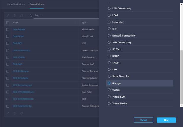
56. Enter the Organization, Name, Description and create a new tag or assign an existing tag. Click Next.
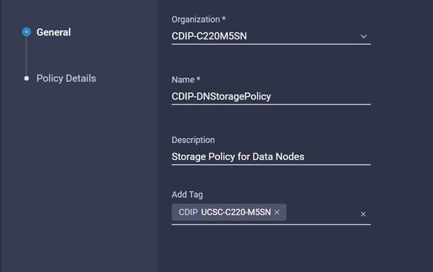
57. Configure the policy details required for Storage Policy.
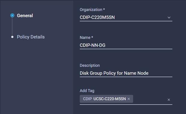
58. Create Disk Group policy for Name Nodes.
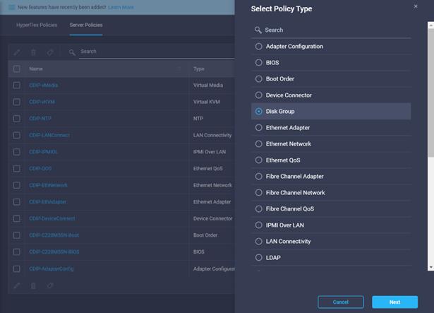
59. Enter the Organization, Name, Description and create a new tag or assign an existing tag. Click Next.
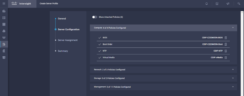
To create the Server Profile for Name Node and Data Node with their corresponding policies configured in the Create Server Policies section, follow these steps:
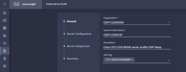
1. Select the Profiles tab and click Create Server Profile.
2. Enter the Organization, Name, Description and create a new tag or assign an existing tag. Click Next.
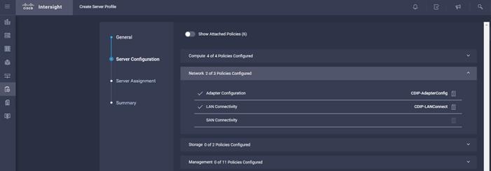
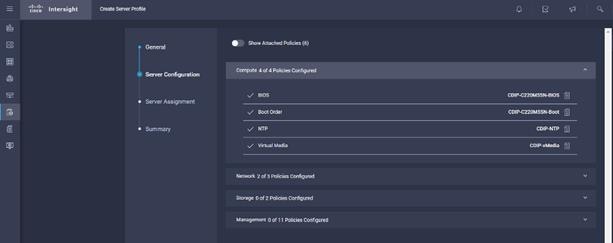
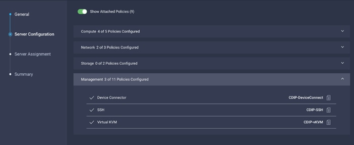
3. Assign the Compute, Network, Storage and Management policies created on the Server Configuration tab.


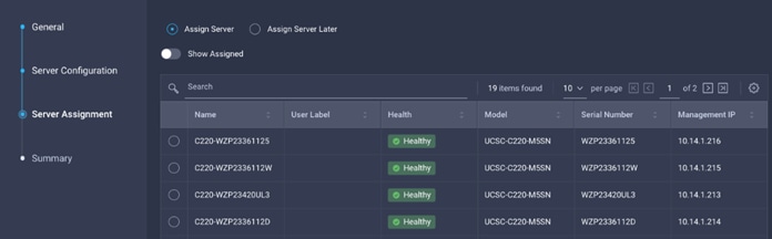
4. Select Assign Server.

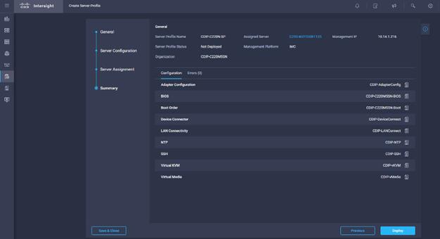
5. Click Next to view the summary configuration. Click Deploy.

6. Create Server Profile clone for multiple servers..

7. Select the Profiles tab and click Create Server Profile.
8. Enter the Organization, Name, Description and create a new tag or assign an existing tag. Click Next.
9. Assign the Compute, Network, Storage and Management policies created on the Server Configuration tab.

10. Select Assign Server.
11. Click Next to view the summary configuration. Click Deploy.
12. Create Server Profile clone for multiple servers.
Install Red Hat Enterprise Linux 7.7
This section provides detailed procedures for installing Red Hat Enterprise Linux Server using associated server profile on Cisco UCS C220 M5 servers. There are multiple ways to install the RHEL operating system. The installation procedure described in this deployment guide uses KVM console and virtual media from Cisco Intersight Server profile.
![]() In this study, RHEL version 7.7 DVD/ISO was utilized for OS the installation on Cisco UCS C220 M5 Rack Servers.
In this study, RHEL version 7.7 DVD/ISO was utilized for OS the installation on Cisco UCS C220 M5 Rack Servers.
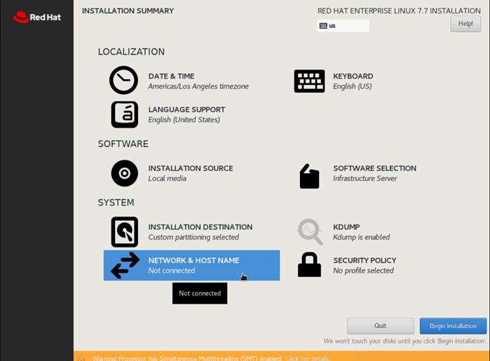
To install the Red Hat Enterprise Linux 7.7 operating system, follow these steps:
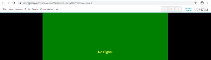
1. On the Server tab in Cisco Intersight, select server. From the list of options select Launch Tunneled vKVM.
![]() We configured Tunneled vKVM and Launched Tunneled vKVM from Cisco Intersight.
We configured Tunneled vKVM and Launched Tunneled vKVM from Cisco Intersight.
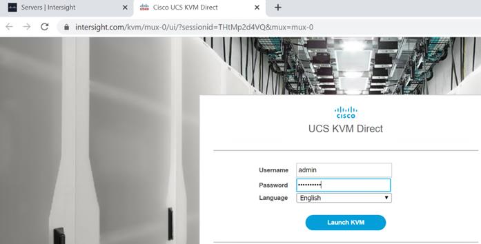
2. Log into UCS KVM Direct with CIMC credential. Click Launch KVM.

The KVM window will appear.
3. Verify that Virtual Device is already mapped in Virtual Media tab as per the Virtual Media Policy.
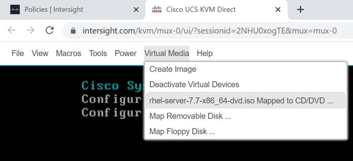
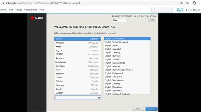
4. Select the Installation option from Red Hat Enterprise Linux 7.7.
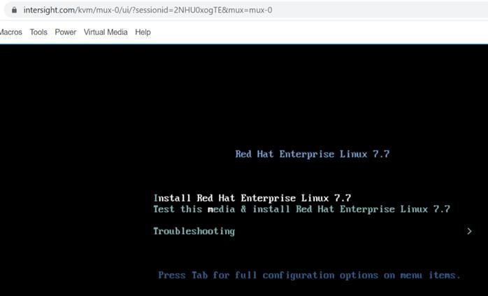
5. Select the language for the installation and click Continue.
6. Select the date and time, which pops up another window. Select the location on the map, set the time, and click Done.
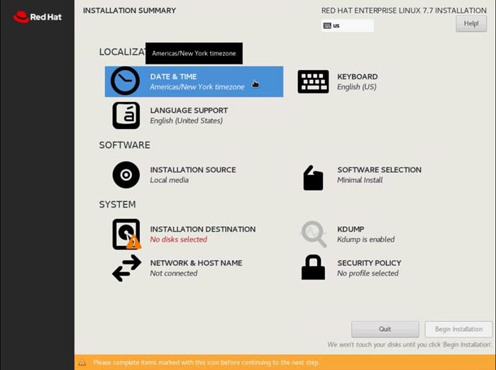
7. Click Installation Destination.
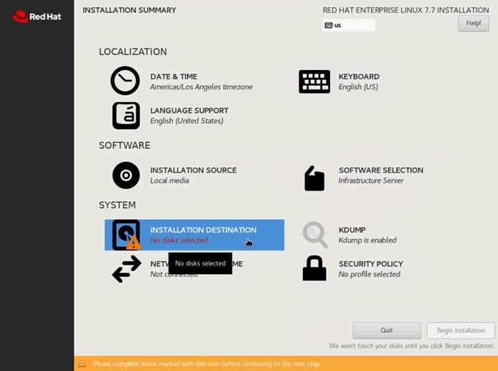
8. This opens a new window with the boot disks. Select a device and choose “I will configure partitioning”. Click Done. We selected two M.2 SATA SSDs.
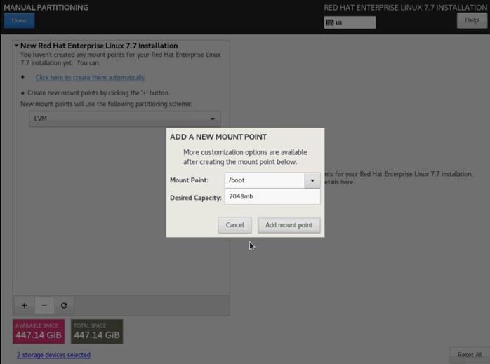
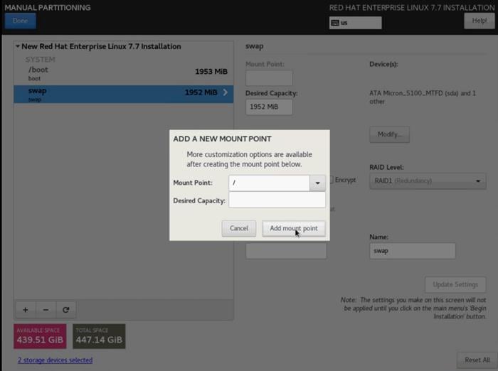
9. This opens a window to create the partitions. Click the + sign to add a new partition as shown below with a boot partition size 2048 MB.
10. Click Add Mount Point to add the partition.
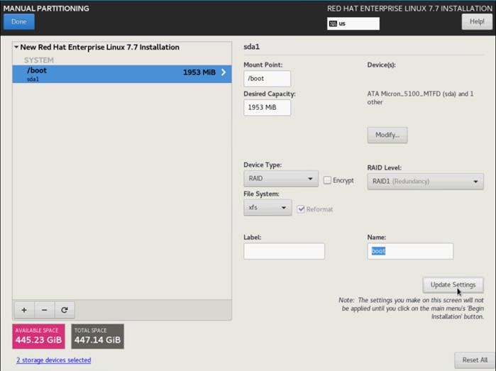
11. Change the device type to RAID and make sure the RAID level is RAID1 (redundancy) and click Update Settings to save the changes.
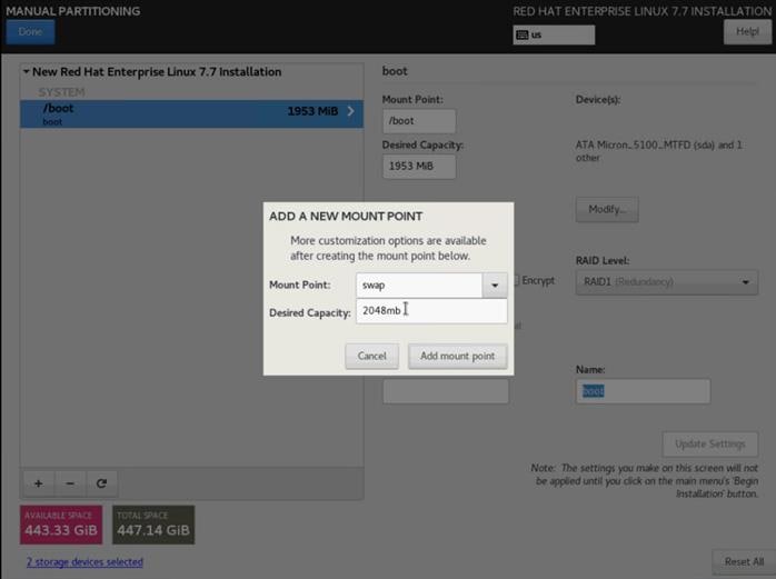
12. Click the + sign to create the swap partition of size 2048 MB. Click Add Mount Point.
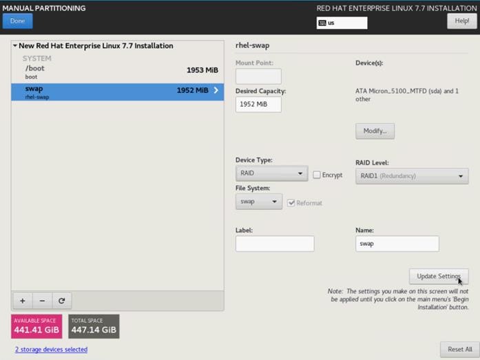
13. Change the Device type to RAID and RAID level to RAID1 (Redundancy) and click Update Settings.
14. Click + to add the / partition. The size can be left empty so it will use the remaining capacity. Click Add Mountpoint.
15. Change the Device type to RAID and RAID level to RAID1 (Redundancy). Click Update Settings.
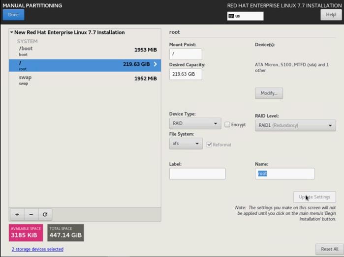
16. Click Done.
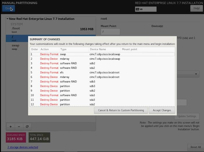
17. Click Accept changes and continue the Installation.
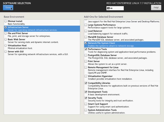
18. Click Software Selection.
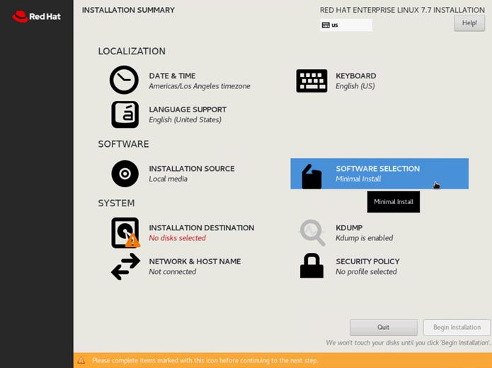
19. Select Infrastructure Server and select the Add-Ons as noted below, then click Done:
◦ Network File System Client
◦ Performance Tools
◦ Compatibility Libraries
◦ Development Tools
◦ Security Tools
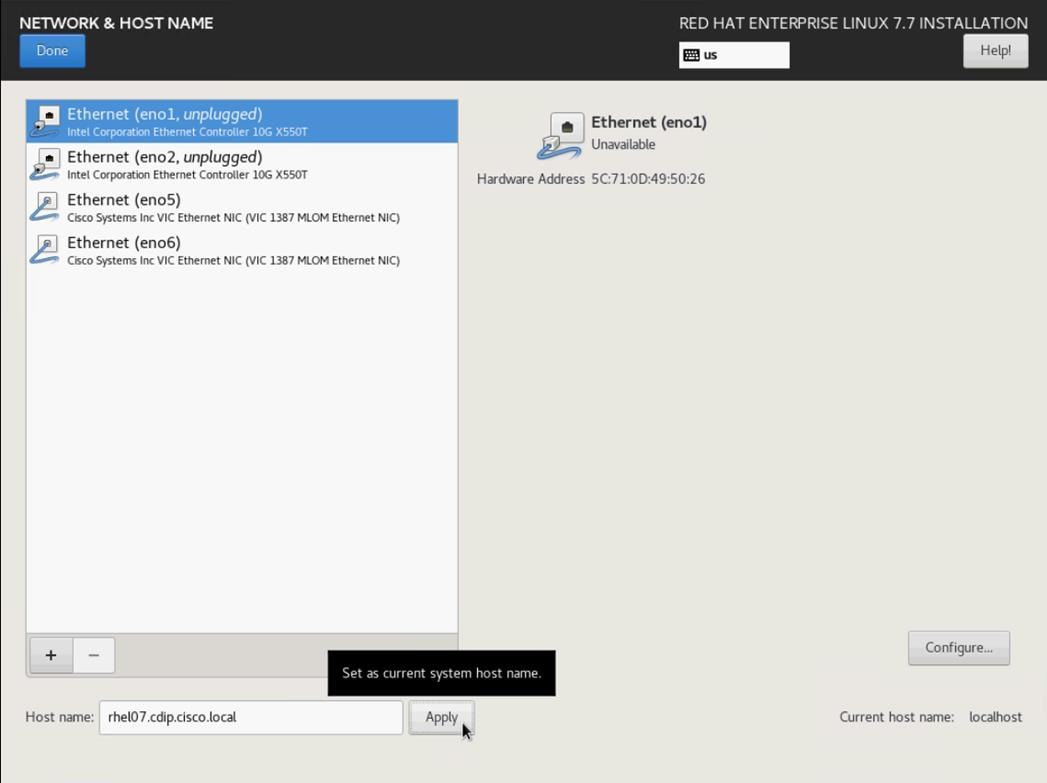
20. Click Network and Hostname and configure Hostname and Networking for the Host.
21. Type in the hostname as shown below.
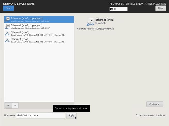
![]() The network configuration is configured at a later time after the installation.
The network configuration is configured at a later time after the installation.
22. Click Save, update the hostname, and turn Ethernet ON. Click Done to return to the main menu.
23. Click Begin Installation in the main menu.
24. Select Root Password in the User Settings.
25. Enter the Root Password and click Done.
26. Once the installation is complete, reboot the system.
27. Repeat steps 1 to 26 to install Red Hat Enterprise Linux 7.7 on Servers 2 through 30.
![]() The OS installation and configuration of the nodes that is mentioned above can be automated through PXE boot or third-party tools.
The OS installation and configuration of the nodes that is mentioned above can be automated through PXE boot or third-party tools.
![]() See the Appendix, section Configure Cisco Boot Optimized M.2 RAID Controller for Installation steps for Cisco Boot Optimized M.2 RAID Controller.
See the Appendix, section Configure Cisco Boot Optimized M.2 RAID Controller for Installation steps for Cisco Boot Optimized M.2 RAID Controller.
The hostnames and their corresponding IP addresses are shown in Table 8.
Table 8 Hostname and IP address
| Hostname |
Bond0 |
| rhelnn01 |
10.14.1.45 |
| rhelnn02 |
10.14.1.46 |
| rhelnn03 |
10.14.1.47 |
| rhel01 |
10.14.1.51 |
| rhel02 |
10.14.1.52 |
| rhel03 |
10.14.1.53 |
| rhel04 |
10.14.1.54 |
| rhel05 |
10.14.1.55 |
| ….. |
….. |
| Rhel15 |
10.14.1.65 |
| Rhel16 |
10.14.1.66 |
![]() Multi-homing configuration is not recommended in this design, so assign only one network interface on each host.
Multi-homing configuration is not recommended in this design, so assign only one network interface on each host.
![]() For simplicity, outbound NATing is configured for internet access when desired, such as accessing public repos and/or accessing Red Hat Content Delivery Network. However, configuring outbound NAT is beyond the scope of this document.
For simplicity, outbound NATing is configured for internet access when desired, such as accessing public repos and/or accessing Red Hat Content Delivery Network. However, configuring outbound NAT is beyond the scope of this document.
Table 9 Hostname and IP address
| Hostname |
Bond0 |
| rhelnn01 |
10.14.1.45 |
| rhelnn02 |
10.14.1.46 |
| rhelnn03 |
10.14.1.47 |
| rhel01 |
10.14.1.51 |
| rhel02 |
10.14.1.52 |
| rhel03 |
10.14.1.53 |
| rhel04 |
10.14.1.54 |
| rhel05 |
10.14.1.55 |
| ….. |
….. |
| Rhel15 |
10.14.1.65 |
| Rhel16 |
10.14.1.66 |
![]() Multi-homing configuration is not recommended in this design, so assign only one network interface on each host.
Multi-homing configuration is not recommended in this design, so assign only one network interface on each host.
![]() For simplicity, outbound NATing is configured for internet access when desired, such as accessing public repos and/or accessing Red Hat Content Delivery Network. However, configuring outbound NAT is beyond the scope of this document.
For simplicity, outbound NATing is configured for internet access when desired, such as accessing public repos and/or accessing Red Hat Content Delivery Network. However, configuring outbound NAT is beyond the scope of this document.
Choose one of the nodes of the cluster or a separate node as the Admin Node for management, such as CDP PvC Base installation, Ansible, creating a local Red Hat repo, and others. In this document, we used rhelnn01 for this purpose.
Configure Network and Bond Interfaces
To configure the network and bond interfaces, follow these steps:
![]() The following section captures configuration details for active-standby network bond configuration. See the Appendix to configure active-active (balance-alb/mod 6 or 802.3ad/mod 4).
The following section captures configuration details for active-standby network bond configuration. See the Appendix to configure active-active (balance-alb/mod 6 or 802.3ad/mod 4).
![]() Based on RHEL the bond mod configuration requires a corresponding configuration on the Cisco Nexus switch.
Based on RHEL the bond mod configuration requires a corresponding configuration on the Cisco Nexus switch.
1. Setup /etc/sysconfig/ifcfg-bond0. Configure the two VNIC interfaces as slave interfaces to the bond interface.
2. Run the following to configure bond on for each Name Node and Data Node:
[root@rhelnn01 ~]# cat /etc/sysconfig/network-scripts/ifcfg-bond0
DEVICE=bond0
NAME=bond0
TYPE=Bond
BONDING_MASTER=yes
IPADDR=10.14.1.45
NETMASK=255.255.255.0
ONBOOT=yes
HOTPLUG=no
BOOTPROTO=none
USERCTL=no
BONDING_OPTS="miimon=100 mode=1 primary=eno5 primary_reselect=0"
NM_CONTROLLED=no
MTU="9000"
[root@rhelnn01 ~]# cat /etc/sysconfig/network-scripts/ifcfg-eno5
TYPE=Ethernet
BOOTPROTO=none
NAME=bond0-slave1
DEVICE=eno5
ONBOOT=no
MASTER=bond0
SLAVE=yes
NM_CONTROLLED=no
HOTPLUG=no
USERCTL=no
MTU="9000"
[root@rhelnn01 ~]# cat /etc/sysconfig/network-scripts/ifcfg-eno6
TYPE=Ethernet
BOOTPROTO=none
NAME=bond0-slave6
DEVICE=eno6
ONBOOT=no
MASTER=bond0
SLAVE=yes
NM_CONTROLLED=no
HOTPLUG=no
USERCTL=no
MTU="9000"
[root@rhelnn01 ~]# ip addr
1: lo: <LOOPBACK,UP,LOWER_UP> mtu 65536 qdisc noqueue state UNKNOWN group default qlen 1000
link/loopback 00:00:00:00:00:00 brd 00:00:00:00:00:00
inet 127.0.0.1/8 scope host lo
valid_lft forever preferred_lft forever
2: eno5: <BROADCAST,MULTICAST,SLAVE,UP,LOWER_UP> mtu 9000 qdisc mq master bond0 state UP group default qlen 1000
link/ether 38:0e:4d:b5:49:d6 brd ff:ff:ff:ff:ff:ff
3: eno6: <BROADCAST,MULTICAST,SLAVE,UP,LOWER_UP> mtu 9000 qdisc mq master bond0 state UP group default qlen 1000
link/ether 38:0e:4d:b5:49:d6 brd ff:ff:ff:ff:ff:ff
4: eno1: <NO-CARRIER,BROADCAST,MULTICAST,UP> mtu 1500 qdisc mq state DOWN group default qlen 1000
link/ether 38:0e:4d:7d:b7:f2 brd ff:ff:ff:ff:ff:ff
5: eno2: <NO-CARRIER,BROADCAST,MULTICAST,UP> mtu 1500 qdisc mq state DOWN group default qlen 1000
link/ether 38:0e:4d:7d:b7:f3 brd ff:ff:ff:ff:ff:ff
6: bond0: <BROADCAST,MULTICAST,MASTER,UP,LOWER_UP> mtu 9000 qdisc noqueue state UP group default qlen 1000
link/ether 38:0e:4d:b5:49:d6 brd ff:ff:ff:ff:ff:ff
inet 10.14.1.45/24 brd 10.14.1.255 scope global bond0
valid_lft forever preferred_lft forever
![]() BONDING_OPTS="miimon=100 mode=1 primary=<Interface Name> primary_reselect=0" – primary reselect default value is 0.
BONDING_OPTS="miimon=100 mode=1 primary=<Interface Name> primary_reselect=0" – primary reselect default value is 0.
Prior to setting up DNS, configure /etc/hosts on the Admin node.
![]() For the purpose of simplicity, /etc/hosts file is configured with hostnames in all the nodes. However, in large scale production grade deployment, DNS server setup is highly recommended. Furthermore, /etc/hosts file is not copied into containers running on the platform.
For the purpose of simplicity, /etc/hosts file is configured with hostnames in all the nodes. However, in large scale production grade deployment, DNS server setup is highly recommended. Furthermore, /etc/hosts file is not copied into containers running on the platform.
Below are the sample A records for DNS configuration within Linux environment:
ORIGIN cdip.cisco.local
rhelnn01 A 10.14.1.45
rhelnn02 A 10.14.1.46
rhelnn03 A 10.14.1.47
rhel01 A 10.14.1.51
rhel02 A 10.14.1.52
rhel03 A 10.14.1.53
…
…
Rhel15 A 10.14.1.65
Rhel16 A 10.14.1.66
To create the host file on the admin node, follow these steps:
1. Log into the Admin Node (rhelnn01).
#ssh 10.14.1.46
2. Populate the host file with IP addresses and corresponding hostnames on the Admin node (rhelnn01) and other nodes as follows:
On Admin Node (rhelnn01):
[root@rhelnn01 ~]# cat /etc/hosts
127.0.0.1 localhost localhost.localdomain localhost4 localhost4.localdomain4
::1 localhost localhost.localdomain localhost6 localhost6.localdomain6
# Name nodes
10.14.1.45 rhelnn01.cdip.cisco.local rhelnn01
10.14.1.46 rhelnn02.cdip.cisco.local rhelnn02
10.14.1.47 rhelnn03.cdip.cisco.local rhelnn03
# Data nodes
10.14.1.51 rhel01.cdip.cisco.local rhel01
10.14.1.52 rhel02.cdip.cisco.local rhel02
10.14.1.53 rhel03.cdip.cisco.local rhel03
10.14.1.54 rhel04.cdip.cisco.local rhel04
10.14.1.55 rhel05.cdip.cisco.local rhel05
10.14.1.56 rhel06.cdip.cisco.local rhel06
10.14.1.57 rhel07.cdip.cisco.local rhel07
10.14.1.58 rhel08.cdip.cisco.local rhel08
10.14.1.59 rhel09.cdip.cisco.local rhel09
10.14.1.60 rhel10.cdip.cisco.local rhel10
10.14.1.61 rhel11.cdip.cisco.local rhel11
10.14.1.62 rhel12.cdip.cisco.local rhel12
10.14.1.63 rhel13.cdip.cisco.local rhel13
10.14.1.64 rhel14.cdip.cisco.local rhel14
10.14.1.65 rhel15.cdip.cisco.local rhel15
10.14.1.66 rhel16.cdip.cisco.local rhel16
To manage all the nodes in a cluster from the admin node password-less login needs to be setup. It assists in automating common tasks with Ansible, and shell-scripts without having to use passwords.
To enable password-less login across all the nodes when Red Hat Linux is installed across all the nodes in the cluster, follow these steps:
1. Log into the Admin Node (rhelnn01).
2. Run the ssh-keygen command to create both public and private keys on the admin node.
# ssh-keygen -N '' -f ~/.ssh/id_rsa
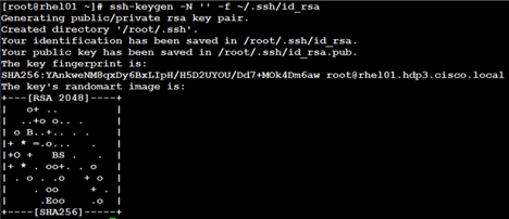
3. Run the following command from the admin node to copy the public key id_rsa.pub to all the nodes of the cluster. ssh-copy-id appends the keys to the remote-hosts .ssh/authorized_keys.
# for i in {01..16}; do echo "copying rhel$i.cdip.cisco.local"; ssh-copy-id -i ~/.ssh/id_rsa.pub root@rhel$i.cdip.cisco.local; done;
4. Enter yes for Are you sure you want to continue connecting (yes/no)?
5. Enter the password of the remote host.
Create a Red Hat Enterprise Linux (RHEL) 7.7 Local Repository
To create a repository using RHEL DVD or ISO on the admin node (in this deployment rhelnn01 is used for this purpose), create a directory with all the required RPMs, run the “createrepo” command and then publish the resulting repository.
To create a RHEL 7.7 local repository, follow these steps:
1. Log into rhelnn01. Create a directory that would contain the repository.
# mkdir -p /var/www/html/rhelrepo
2. Copy the contents of the Red Hat DVD to /var/www/html/rhelrepo
3. Alternatively, if you have access to a Red Hat ISO Image, Copy the ISO file to rhelnn01.
4. Log back into rhelnn01 and create the mount directory.
# scp rhel-server-7.7-x86_64-dvd.iso rhelnn01:/root/
# mkdir -p /mnt/rheliso
# mount -t iso9660 -o loop /root/rhel-server-7.7-x86_64-dvd.iso /mnt/rheliso/
5. Copy the contents of the ISO to the /var/www/html/rhelrepo directory.
# cp -r /mnt/rheliso/* /var/www/html/rhelrepo
6. On rhelnn01 create a .repo file to enable the use of the yum command.
# vi /var/www/html/rhelrepo/rheliso.repo
[rhel7.7]
name=Red Hat Enterprise Linux 7.7
baseurl=http://10.14.1.46/rhelrepo
gpgcheck=0
enabled=1
7. Copy rheliso.repo file from /var/www/html/rhelrepo to /etc/yum.repos.d on rhelnn01.
# cp /var/www/html/rhelrepo/rheliso.repo /etc/yum.repos.d/
![]() Based on this repository file, yum requires httpd to be running on rhelnn01 for other nodes to access the repository.
Based on this repository file, yum requires httpd to be running on rhelnn01 for other nodes to access the repository.
8. To make use of repository files on rhelnn01 without httpd, edit the baseurl of repo file /etc/yum.repos.d/rheliso.repo to point repository location in the file system.
![]() This step is needed to install software on Admin Node (rhelnn01) using the repo (such as httpd, create-repo, and so on.)
This step is needed to install software on Admin Node (rhelnn01) using the repo (such as httpd, create-repo, and so on.)
# vi /etc/yum.repos.d/rheliso.repo
[rhel7.7]
name=Red Hat Enterprise Linux 7.7
baseurl=file:///var/www/html/rhelrepo
gpgcheck=0
enabled=1
Create the Red Hat Repository Database
To create the Red Hat repository database, follow these steps:
1. Install the “createrepo” package on admin node (rhelnn01). Use it to regenerate the repository database(s) for the local copy of the RHEL DVD contents.
# yum -y install createrepo
2. Run “createrepo” on the RHEL repository to create the repo database on admin node
# cd /var/www/html/rhelrepo
# createrepo .
![]()
To set up Ansible, follow these steps:
1. Download Ansible rpm from the this link: https://releases.ansible.com/ansible/rpm/release/epel-7-x86_64/ansible-2.9.6-1.el7.ans.noarch.rpm
# wget https://releases.ansible.com/ansible/rpm/release/epel-7-x86_64/ansible-2.9.6-1.el7.ans.noarch.rpm
2. Run the following command to install ansible:
# yum localinstall -y ansible-2.9.6-1.el7.ans.noarch.rpm
3. Verify Ansible installation by running the following commands:
# ansible --version
ansible 2.9.6
config file = /etc/ansible/ansible.cfg
configured module search path = [u'/root/.ansible/plugins/modules', u'/usr/share/ansible/plugins/modules']
ansible python module location = /usr/lib/python2.7/site-packages/ansible
executable location = /usr/bin/ansible
python version = 2.7.5 (default, Jun 11 2019, 14:33:56) [GCC 4.8.5 20150623 (Red Hat 4.8.5-39)]
# ansible localhost -m ping
localhost | SUCCESS => {
"changed": false,
"ping": "pong"
}
4. Prepare the host inventory file for Ansible as shown below. Various host groups have been created based on any specific installation requirements of certain hosts.
[root@rhelnn01 ~]# cat /etc/ansible/hosts
[admin]
rhelnn01.cdip.cisco.local
[namenodes]
rhelnn01.cdip.cisco.local
rhelnn02.cdip.cisco.local
rhelnn03.cdip.cisco.local
[datanodes]
rhel01.cdip.cisco.local
rhel02.cdip.cisco.local
rhel03.cdip.cisco.local
rhel04.cdip.cisco.local
rhel05.cdip.cisco.local
rhel06.cdip.cisco.local
rhel07.cdip.cisco.local
rhel08.cdip.cisco.local
rhel09.cdip.cisco.local
rhel10.cdip.cisco.local
rhel11.cdip.cisco.local
rhel12.cdip.cisco.local
rhel13.cdip.cisco.local
rhel14.cdip.cisco.local
rhel15.cdip.cisco.local
rhel16.cdip.cisco.local
[nodes]
rhelnn01.cdip.cisco.local
rhelnn02.cdip.cisco.local
rhelnn03.cdip.cisco.local
rhel01.cdip.cisco.local
rhel02.cdip.cisco.local
rhel03.cdip.cisco.local
rhel04.cdip.cisco.local
rhel05.cdip.cisco.local
rhel06.cdip.cisco.local
rhel07.cdip.cisco.local
rhel08.cdip.cisco.local
rhel09.cdip.cisco.local
rhel10.cdip.cisco.local
rhel11.cdip.cisco.local
rhel12.cdip.cisco.local
rhel13.cdip.cisco.local
rhel14.cdip.cisco.local
rhel15.cdip.cisco.local
rhel16.cdip.cisco.local
5. Verify host group by running the following command.
# ansible datanodes -m ping
Setting up the RHEL repository on the admin node requires httpd. To set up RHEL repository on the admin node, follow these steps:
1. Install httpd on the admin node to host repositories:
![]() The Red Hat repository is hosted using HTTP on the admin node; this machine is accessible by all the hosts in the cluster.
The Red Hat repository is hosted using HTTP on the admin node; this machine is accessible by all the hosts in the cluster.
# yum -y install httpd
2. Add ServerName and make the necessary changes to the server configuration file:
# vi /etc/httpd/conf/httpd.conf
ServerName 10.14.1.46:80
3. Start httpd:
# service httpd start
# chkconfig httpd on
![]() The default Linux firewall settings are too restrictive for any Hadoop deployment. Since the Cisco UCS Big Data deployment will be in its own isolated network there is no need for that additional firewall.
The default Linux firewall settings are too restrictive for any Hadoop deployment. Since the Cisco UCS Big Data deployment will be in its own isolated network there is no need for that additional firewall.
To disable the Linux firewall, run the following:
# ansible all -m command -a "firewall-cmd --zone=public --add-port=80/tcp --permanent"
# ansible all -m command -a "firewall-cmd --reload"
# ansible all -m command -a "systemctl disable firewalld"
![]() SELinux must be disabled during the install procedure and cluster setup. SELinux can be enabled after installation and while the cluster is running.
SELinux must be disabled during the install procedure and cluster setup. SELinux can be enabled after installation and while the cluster is running.
SELinux can be disabled by editing /etc/selinux/config and changing the SELINUX line to SELINUX=disabled.
To disable SELinux, follow these steps:
1. The following command will disable SELINUX on all nodes:
![]() This command may fail if SELinux is already disabled. This requires reboot to take effect.
This command may fail if SELinux is already disabled. This requires reboot to take effect.
# ansible nodes -m shell -a "sed –i 's/SELINUX=enforcing/SELINUX=disabled/g' /etc/selinux/config"
# ansible nodes -m shell -a "setenforce 0"
2. Reboot the machine, if needed for SELinux to be disabled in case it does not take effect. It can be checked using the following command:
# ansible namenodes -a "sestatus"
rhel01.cdp.cisco.local | CHANGED | rc=0 >>
SELinux status: disabled
rhel02.cdp.cisco.local | CHANGED | rc=0 >>
SELinux status: disabled
rhel03.cdp.cisco.local | CHANGED | rc=0 >>
SELinux status: disabled
Set Up All Nodes to use the RHEL Repository
To set up all noes to use the RHEL repository, follow these steps:
![]() Based on this repository file, yum requires httpd to be running on rhel1 for other nodes to access the repository.
Based on this repository file, yum requires httpd to be running on rhel1 for other nodes to access the repository.
1. Copy the rheliso.repo to all the nodes of the cluster:
# ansible nodes -m copy -a "src=/var/www/html/rhelrepo/rheliso.repo dest=/etc/yum.repos.d/."
2. Copy the /etc/hosts file to all nodes:
# ansible nodes -m copy -a "src=/etc/hosts dest=/etc/hosts"
3. Purge the yum caches:
# ansible nodes -a “yum clean all”
# ansible nodes -a “yum repolist”
![]() While the suggested configuration is to disable SELinux, if for any reason SELinux needs to be enabled on the cluster, run the following command to make sure that the httpd can read the Yum repofiles.
While the suggested configuration is to disable SELinux, if for any reason SELinux needs to be enabled on the cluster, run the following command to make sure that the httpd can read the Yum repofiles.
Upgrade the Cisco Network Driver for VIC1387
The latest Cisco Network driver is required for performance and updates. The latest drivers can be downloaded from the link below:
https://software.cisco.com/download/home/283862063/type/283853158/release/4.1(1a)
To upgrade the Cisco Network Driver for VIC1387, follow these steps:
1. From a node connected to the Internet, download, extract, and transfer kmod-enic-.rpm to rhelnn01 (admin node).
2. Copy the rpm on all nodes of the cluster using the following Ansible commands. For this example, the rpm is assumed to be in present working directory of rhelnn01:
[root@rhelnn01 ~]# ansible all -m copy -a "src=/root/ kmod-enic-4.0.0.8-802.24.rhel7u7.x86_64.rpm dest=/root/."
3. Use the yum module to install the enic driver rpm file on all the nodes through Ansible:
[root@rhelnn01 ~]# ansible all –m yum –a “name=/root/ kmod-enic-4.0.0.8-802.24.rhel7u7.x86_64.rpm state=present”
Make sure that the above installed version of kmod-enic driver is being used on all nodes by running the command "modinfo enic" on all nodes:
[root@rhel02 ~]# ansible all -m shell -a "modinfo enic | head -5"
4. It is recommended to download the kmod-megaraid driver for higher performance on Name nodes. The RPM can be found in the same package at: \Storage\LSI\Cisco_Storage_12G_SAS_RAID_controller\RHEL\RHEL7.7\kmod-megaraid_sas-07.710.06.00_el7.7-1.x86_64.rpm:
5. Copy the rpm on all Name nodes of the cluster using the following Ansible commands. For this example, the rpm is assumed to be in present working directory of rhelnn01:
6. Use the yum module to install the megaraid driver rpm file on all the Name nodes using Ansible:
Make sure that the above installed version of kmod-megaraid driver is being used on all nodes by running the command "modinfo megaraid_sas" on all nodes:
[root@rhelnn01 ~]# ansible all -m shell -a "modinfo megaraid_sas | head -5"
The SPDK NVMe device driver is a user space, polled-mode, asynchronous, lockless NVMe driver. This driver provides zero-copy, highly parallel access directly to an SSD from a user space application. The driver runs in userspace, which avoids syscalls and enables zero-copy access from the application using the driver. The SPDK NVMe driver addresses the issue of interrupt latency by polling the storage device for completions instead of relying on interrupts, which effectively lowers both total latency and latency variance. Finally, the driver avoids all locks in the I/O path for maximum scalability.
SPDK provides a block stack with a unified API for talking to different storage backend devices(NVMe SSDs, PMEM, ramdisk, Ceph RBD, virtio-scsi/blk and so on).
SPDK provides an NVMe-oF target application that is capable of serving disks over the network via different transports; RDMA (iWARP, RoCE), InfiniBand™, Intel® Omni-Path Architecture. SPDK provide a unified interface for the NVMe driver and the NVMe-oF Initiator, so whether you’re talking to locally PCIe-attached NVMe devices or remote NVMe devices over a Fabric you can use the same API in your application. SPDK is an open-source project under the BSD license which allows users to integrate any or all of the components under the most permissive licensing terms.
The total time it takes to read/write a block of data from/to an NVMe SSD is a function of the NVMe device latency and the NVMe driver latency. The device latency depends on the block size of the workload. NVMe SSDs can read/write a small block (4KiB) in less than 100 microseconds and have IOPS throughput of over 500K I/O per second. Therefore, even a small improvement of a few microseconds in the transaction time of a single I/O translates into huge saving in CPU cycles when building systems with many SSDs.
The SPDK open-source community redesigned storage software to highlight the outstanding efficiency enabled by running software optimized for NVMe SSDs. The SPDK NVMe driver has demonstrated that millions of I/Os per second per CPU core are easily attainable with no additional offload hardware for small block workloads(4KiB). For large block workloads (> 1MB) the device latency is much higher com-pared to the NVMe driver latency and the I/O per second are much lower, so savings of a few microseconds will not reduce the total transaction time significantly or improve the IOPS throughput noticeably.
![]() Intel SPDK driver requires RHEL version 8.1 and later which reduces latency and required number of cores. Intel SPDK driver requires kernel version 5.7 and later.
Intel SPDK driver requires RHEL version 8.1 and later which reduces latency and required number of cores. Intel SPDK driver requires kernel version 5.7 and later.
![]() For more information on SPDK, go to: https://spdk.io/.
For more information on SPDK, go to: https://spdk.io/.
To setup JAVA, follow these steps:
![]() CDP PvC Base 7 requires JAVA 8.
CDP PvC Base 7 requires JAVA 8.
1. Download jdk-8u241-linux-x64.rpm and src the rpm to admin node (rhelnn01) from the link: https://www.oracle.com/technetwork/java/javase/downloads/jdk8-downloads-2133151.html
2. Copy JDK rpm to all nodes:
# ansible nodes -m copy -a "src=/root/jdk-8u241-linux-x64.rpm dest=/root/."
3. Extract and Install JDK all nodes:
# ansible all -m command -a "rpm -ivh jdk-8u241-linux-x64.rpm "
4. Create the following files java-set-alternatives.sh and java-home.sh on admin node (rhelnn01):
# vi java-set-alternatives.sh
#!/bin/bash
for item in java javac javaws jar jps javah javap jcontrol jconsole jdb; do
rm -f /var/lib/alternatives/$item
alternatives --install /usr/bin/$item $item /usr/java/jdk1.8.0_241-amd64/bin/$item 9
alternatives --set $item /usr/java/jdk1.8.0_241-amd64/bin/$item
done
# vi java-home.sh
export JAVA_HOME=/usr/java/jdk1.8.0_241-amd64
5. Make the two java scripts created above executable:
chmod 755 ./java-set-alternatives.sh ./java-home.sh
6. Copying java-set-alternatives.sh to all nodes:
ansible nodes -m copy -a "src=/root/java-set-alternatives.sh dest=/root/."
ansible nodes -m file -a "dest=/root/java-set-alternatives.sh mode=755"
ansible nodes -m copy -a "src=/root/java-home.sh dest=/root/."
ansible nodes -m file -a "dest=/root/java-home.sh mode=755"
7. Setup Java Alternatives:
[root@rhelnn01 ~]# ansible all -m shell -a "/root/java-set-alternatives.sh"
8. Make sure correct java is setup on all nodes (should point to newly installed java path):
# ansible all -m shell -a "alternatives --display java | head -2"
rhelnn01.cdip.cisco.local | CHANGED | rc=0 >>
java - status is manual.
link currently points to /usr/java/jdk1.8.0_241-amd64/bin/java
rhelnn02.cdip.cisco.local | CHANGED | rc=0 >>
java - status is manual.
link currently points to /usr/java/jdk1.8.0_241-amd64/bin/java
rhelnn03.cdip.cisco.local | CHANGED | rc=0 >>
java - status is manual.
link currently points to /usr/java/jdk1.8.0_241-amd64/bin/java
rhel02.cdip.cisco.local | CHANGED | rc=0 >>
java - status is manual.
link currently points to /usr/java/jdk1.8.0_241-amd64/bin/java
rhel01.cdip.cisco.local | CHANGED | rc=0 >>
java - status is manual.
link currently points to /usr/java/jdk1.8.0_241-amd64/bin/java
9. Setup JAVA_HOME on all nodes:
# ansible all -m copy -a "src=/root/java-home.sh dest=/etc/profile.d"
10. Display JAVA_HOME on all nodes:
# ansible all -m command -a "echo $JAVA_HOME"
rhelnn01.cdip.cisco.local | CHANGED | rc=0 >>
/usr/java/jdk1.8.0_241-amd64
11. Display current java –version:
# ansible all -m command -a "java -version"
rhelnn01.cdip.cisco.local | CHANGED | rc=0 >>
java version "1.8.0_241"
Java(TM) SE Runtime Environment (build 1.8.0_241-b07)
Java HotSpot(TM) 64-Bit Server VM (build 25.241-b07, mixed mode)
Syslog must be enabled on each node to preserve logs regarding killed processes or failed jobs. Modern versions such as syslog-ng and rsyslog are possible, making it more difficult to be sure that a syslog daemon is present.
Use one of the following commands to confirm that the service is properly configured:
# ansible all -m command -a "rsyslogd –v"
# ansible all -m command -a "service rsyslog status"
On each node, ulimit -n specifies the number of inodes that can be opened simultaneously. With the default value of 1024, the system appears to be out of disk space and shows no inodes available. This value should be set to 64000 on every node.
![]() Higher values are unlikely to result in an appreciable performance gain.
Higher values are unlikely to result in an appreciable performance gain.
To set ulimit, follow these steps:
1. For setting the ulimit on Redhat, edit “/etc/security/limits.conf” on admin node rhelnn01 and add the following lines:
2. Copy the /etc/security/limits.conf file from admin node (rhelnn01) to all the nodes using the following command:
# ansible nodes -m copy -a "src=/etc/security/limits.conf dest=/etc/security/limits.conf"
3. Make sure that the /etc/pam.d/su file contains the following settings:
# cat /etc/pam.d/su
#%PAM-1.0
auth sufficient pam_rootok.so
# Uncomment the following line to implicitly trust users in the "wheel" group.
#auth sufficient pam_wheel.so trust use_uid
# Uncomment the following line to require a user to be in the "wheel" group.
#auth required pam_wheel.so use_uid
auth include system-auth
auth include postlogin
account sufficient pam_succeed_if.so uid = 0 use_uid quiet
account include system-auth
password include system-auth
session include system-auth
session include postlogin
session optional pam_xauth.so
4. Copy the /etc/pam.d/su file from admin node (rhelnn01) to all the nodes using the following command:
# ansible nodes -m copy -a "src=/etc/pam.d/su dest/etc/pam.d/su"
![]() The ulimit values are applied on a new shell, running the command on a node on an earlier instance of a shell will show old values.
The ulimit values are applied on a new shell, running the command on a node on an earlier instance of a shell will show old values.
Adjusting the tcp_retries parameter for the system network enables faster detection of failed nodes. Given the advanced networking features of Cisco UCS, this is a safe and recommended change (failures observed at the operating system layer are most likely serious rather than transitory).
To set TCP retries, follow these steps:
![]() On each node, set the number of TCP retries to 5 can help detect unreachable nodes with less latency.
On each node, set the number of TCP retries to 5 can help detect unreachable nodes with less latency.
1. Edit the file /etc/sysctl.conf and on admin node rhelnn01 and add the following:
net.ipv4.tcp_retries2=5
2. Copy the /etc/sysctl.conf file from admin node (rhelnn01) to all the nodes using the following command:
# ansible nodes -m copy -a "src=/etc/sysctl.conf dest=/etc/sysctl.conf"
3. Load the settings from default sysctl file /etc/sysctl.conf by running the following command:
# ansible nodes -m command -a "sysctl -p"
To disable IPv6 defaults, follow these steps:
1. Run the following command:
# ansible all -m shell -a "echo 'net.ipv6.conf.all.disable_ipv6 = 1' >> /etc/sysctl.conf"
# ansible all -m shell -a "echo 'net.ipv6.conf.default.disable_ipv6 = 1' >> /etc/sysctl.conf"
# ansible all -m shell -a "echo 'net.ipv6.conf.lo.disable_ipv6 = 1' >> /etc/sysctl.conf"
Load the settings from default sysctl file /etc/sysctl.conf:
# ansible all -m shell -a "sysctl –p"
To disable swapping, follow these steps:
1. Run the following on all nodes. Variable vm.swappiness defines how often swap should be used, 60 is default:
# ansible all -m shell -a "echo 'vm.swappiness=0' >> /etc/sysctl.conf"
2. Load the settings from default sysctl file /etc/sysctl.conf and verify the content of sysctl.conf:
# ansible all -m shell -a "sysctl –p"
# ansible all -m shell -a "cat /etc/sysctl.conf"
To disable Memory Overcommit, follow these steps:
1. Run the following on all nodes. Variable vm.overcommit_memory=0
# ansible all -m shell -a "echo 'vm.overcommit_memory=0' >> /etc/sysctl.conf"
2. Load the settings from default sysctl file /etc/sysctl.conf and verify the content of sysctl.conf:
# ansible all -m shell -a "sysctl –p"
# ansible all -m shell -a "cat /etc/sysctl.conf"
rhelnn01.cdip.cisco.local | CHANGED | rc=0 >>
# sysctl settings are defined through files in
# /usr/lib/sysctl.d/, /run/sysctl.d/, and /etc/sysctl.d/.
#
# Vendors settings live in /usr/lib/sysctl.d/.
# To override a whole file, create a new file with the same in
# /etc/sysctl.d/ and put new settings there. To override
# only specific settings, add a file with a lexically later
# name in /etc/sysctl.d/ and put new settings there.
#
# For more information, see sysctl.conf(5) and sysctl.d(5).
net.ipv4.tcp_retries2=5
net.ipv6.conf.all.disable_ipv6 = 1
net.ipv6.conf.default.disable_ipv6 = 1
net.ipv6.conf.lo.disable_ipv6 = 1
vm.swappiness=0
vm.overcommit_memory=0
Disable Transparent Huge Pages
Disabling Transparent Huge Pages (THP) reduces elevated CPU usage caused by THP.
To disable Transparent Huge Pages, follow these steps:
1. You must run the following commands for every reboot; copy this command to /etc/rc.d/rc.local so they are executed automatically for every reboot:
# ansible all -m shell -a "echo never > /sys/kernel/mm/transparent_hugepage/enabled”
# ansible all -m shell -a "echo never > /sys/kernel/mm/transparent_hugepage/defrag"
2. On the Admin node, run the following commands:
#rm –f /root/thp_disable
#echo "echo never > /sys/kernel/mm/transparent_hugepage/enabled" >>
/root/thp_disable
#echo "echo never > /sys/kernel/mm/transparent_hugepage/defrag " >>
/root/thp_disable
3. Copy file to each node:
# ansible nodes -m copy -a "src=/root/thp_disable dest=/root/thp_disable"
4. Append the content of file thp_disable to /etc/rc.d/rc.local:
# ansible nodes -m shell -a "cat /root/thp_disable >> /etc/rc.d/rc.local"
# ansible nodes -m shell -a "chmod +x /etc/rc.d/rc.local"
The Network Time Protocol (NTP) is used to synchronize the time of all the nodes within the cluster. The Network Time Protocol daemon (ntpd) sets and maintains the system time of day in synchronism with the timeserver located in the admin node (rhelnn01). Configuring NTP is critical for any Hadoop Cluster. If server clocks in the cluster drift out of sync, serious problems will occur with HBase and other services.
To configure NTP, follow these steps:
1. Run the following:
# ansible all -m yum -a "name=ntp state=present"
![]() Installing an internal NTP server keeps your cluster synchronized even when an outside NTP server is inaccessible.
Installing an internal NTP server keeps your cluster synchronized even when an outside NTP server is inaccessible.
2. Configure /etc/ntp.conf on the admin node only with the following contents:
# vi /etc/ntp.conf
driftfile /var/lib/ntp/drift
restrict 127.0.0.1
restrict -6 ::1
server 127.127.1.0
fudge 127.127.1.0 stratum 10
includefile /etc/ntp/crypto/pw
keys /etc/ntp/keys
3. Create /root/ntp.conf on the admin node and copy it to all nodes:
# vi /root/ntp.conf
server 10.14.1.46
driftfile /var/lib/ntp/drift
restrict 127.0.0.1
restrict -6 ::1
includefile /etc/ntp/crypto/pw
keys /etc/ntp/keys
4. Copy ntp.conf file from the admin node to /etc of all the data nodes and two other name nodes by executing the following commands in the admin node (rhelnn01):
# ansible datanodes -m copy -a “src=/root/ntp.conf dest=/etc/ntp.conf”
# ansible rhelnn01 -m copy -a “src=/root/ntp.conf dest=/etc/ntp.conf”
# ansible rhelnn03 -m copy -a “src=/root/ntp.conf dest=/etc/ntp.conf”
Run the following to syncronize the time and restart NTP daemon on all nodes:
# ansible all -m service -a “name=ntpd state=stopped”
# systemctl start ntpd (On admin node)
# ansible all -m command -a “ntpdate rhelnn01.cdip.cisco.local”
# ansible all -m service -a “name=ntpd state=started”
5. Make sure to restart of NTP daemon across reboots:
# ansible all -a "systemctl enable ntpd"
6. Verify NTP is up and running in all nodes by running the following commands:
# ansible all -a "systemctl status ntpd"
![]() Alternatively, the new Chrony service can be installed, which is quicker to synchronize clocks in mobile and virtual systems.
Alternatively, the new Chrony service can be installed, which is quicker to synchronize clocks in mobile and virtual systems.
7. Install the Chrony service:
# ansible all -m yum -a "name=chrony state=present"
8. Activate the Chrony service at boot:
# ansible all -a "systemctl enable chronyd"
9. Start the Chrony service:
# ansible all -m service -a "name=chronyd state=started"
# systemctl start chronyd
The Chrony configuration is in the /etc/chrony.conf file, configured similar to /etc/ntp.conf.
Configure the Filesystem for NameNodes and DataNodes
The following script formats and mounts the available volumes on each node whether it is NameNode or Data node. OS boot partition will be skipped. All drives are mounted based on their UUID as /data/disk1, /data/disk2, and so on.
To configure the filesystem for NameNodes and DataNodes, follow these steps:
1. On the Admin node, create a file containing the following script:
#vi /root/driveconf.sh
2. To create partition tables and file systems on the local disks supplied to each of the nodes, run the following script as the root user on each node:
![]() This script assumes there are no partitions already existing on the data volumes. If there are partitions, delete them before running the script. For detailed information, go to section Delete Partitions.
This script assumes there are no partitions already existing on the data volumes. If there are partitions, delete them before running the script. For detailed information, go to section Delete Partitions.
#vi /root/driveconf.sh
#!/bin/bash
#disks_count=`lsblk -id | grep sd | wc -l`
#if [ $disks_count -eq 24 ]; then
# echo "Found 24 disks"
#else
# echo "Found $disks_count disks. Expecting 24. Exiting.."
# exit 1
#fi
[[ "-x" == "${1}" ]] && set -x && set -v && shift 1
count=1
for X in /sys/class/scsi_host/host?/scan
do
echo '- - -' > ${X}
done
for X in /dev/sd?
do
echo "========"
echo $X
echo "========"
if [[ -b ${X} && `/sbin/parted -s ${X} print quit|/bin/grep -c boot` -ne 0
]]
then
echo "$X bootable - skipping."
continue
else
Y=${X##*/}1
echo "Formatting and Mounting Drive => ${X}"
/sbin/mkfs.xfs -f ${X}
(( $? )) && continue
#Identify UUID
UUID=`blkid ${X} | cut -d " " -f2 | cut -d "=" -f2 | sed 's/"//g'`
/bin/mkdir -p /data/disk${count}
(( $? )) && continue
echo "UUID of ${X} = ${UUID}, mounting ${X} using UUID on /data/disk${count}"
/bin/mount -t xfs -o inode64,noatime -U ${UUID} /data/disk${count}
(( $? )) && continue
echo "UUID=${UUID} /data/disk${count} xfs inode64,noatime 0 0" >> /etc/fstab
((count++))
fi
done
3. Run the following command to copy driveconf.sh to all the nodes:
# chmod 755 /root/driveconf.sh
# ansible namenodes -m copy -a “src=/root/driveconf.sh dest=/root/.”
# ansible namenodes -m file -a "dest=/root/driveconf.sh mode=755"
4. Run the following command from the admin node to run the script across all name nodes:
# ansible namenodes -m shell -a “/root/driveconf.sh”
5. Run the following from the admin node to list the partitions and mount points:
# ansible namenodes -m shell -a “df -h”
# ansible namenodes -m shell -a “mount”
# ansible namenodes -m shell -a “cat /etc/fstab”
6. On the Admin node, create a file containing the following script for data nodes:
#vi /root/driveconf_nvme.sh
7. To create partition tables and file systems on the local disks supplied to each of the nodes, run the following script as the root user on each node:
![]() This script assumes there are no partitions already existing on the data volumes. If there are partitions, delete them before running the script. For detailed information, go to section Delete Partitions.
This script assumes there are no partitions already existing on the data volumes. If there are partitions, delete them before running the script. For detailed information, go to section Delete Partitions.
#vi /root/driveconf_nvme.sh
#!/bin/bash
#disks_count=`lsblk -id | grep sd | wc -l`
#if [ $disks_count -eq 24 ]; then
# echo "Found 24 disks"
#else
# echo "Found $disks_count disks. Expecting 24. Exiting.."
# exit 1
#fi
[[ "-x" == "${1}" ]] && set -x && set -v && shift 1
count=1
for X in /sys/class/scsi_host/host?/scan
do
echo '- - -' > ${X}
done
for X in /dev/nvme?n1
do
echo "========"
echo $X
echo "========"
if [[ -b ${X} && `/sbin/parted -s ${X} print quit|/bin/grep -c boot` -ne 0
]]
then
echo "$X bootable - skipping."
continue
else
Y=${X##*/}1
echo "Formatting and Mounting Drive => ${X}"
/sbin/mkfs.xfs -f ${X}
(( $? )) && continue
#Identify UUID
UUID=`blkid ${X} | cut -d " " -f2 | cut -d "=" -f2 | sed 's/"//g'`
/bin/mkdir -p /data/disk${count}
(( $? )) && continue
echo "UUID of ${X} = ${UUID}, mounting ${X} using UUID on /data/disk${count}"
/bin/mount -t xfs -o inode64,noatime -U ${UUID} /data/disk${count}
(( $? )) && continue
echo "UUID=${UUID} /data/disk${count} xfs inode64,noatime 0 0" >> /etc/fstab
((count++))
fi
done
8. Run the following command to copy driveconf.sh to all the nodes:
# chmod 755 /root/driveconf_nvme.sh
# ansible datanodes -m copy -a “src=/root/driveconf_nvme.sh dest=/root/.”
# ansible datanodes -m file -a "dest=/root/driveconf_nvme.sh mode=755"
9. Run the following command from the admin node to run the script across all data nodes:
# ansible datanodes -m shell -a “/root/driveconf_nvme.sh”
10. Run the following from the admin node to list the partitions and mount points:
# ansible datanodes -m shell -a “df –h”
# ansible datanodes -m shell -a “mount”
# ansible datanodes -m shell -a “cat /etc/fstab”
To delete a partition, follow these steps:
1. Run the mount command (‘mount’) to identify which drive is mounted to which device /dev/sd<?>
2. Umount the drive for the partition that needs to be deleted and run fdisk to delete as shown below.
![]() Do not delete the OS partition since this will wipe out the OS.
Do not delete the OS partition since this will wipe out the OS.
# mount
# umount /data/disk1 ? (disk1 shown as example)
#(echo d; echo w;) | sudo fdisk /dev/sd<?>
This section explains the steps to create the script cluster_verification.sh that helps to verify the CPU, memory, NIC, and storage adapter settings across the cluster on all nodes. This script also checks additional prerequisites such as NTP status, SELinux status, ulimit settings, JAVA_HOME settings and JDK version, IP address and hostname resolution, Linux version and firewall settings.
To verify a cluster, follow these steps:
![]() The following script uses cluster shell (clush) which needs to be installed and configured.
The following script uses cluster shell (clush) which needs to be installed and configured.
1. Create the script cluster_verification.sh as shown, on the Admin node (rhelnn01).
#vi cluster_verification.sh
#!/bin/bash
shopt -s expand_aliases,
# Setting Color codes
green='\e[0;32m'
red='\e[0;31m'
NC='\e[0m' # No Color
echo -e "${green} === Cisco UCS Integrated Infrastructure for Big Data and Analytics \ Cluster Verification === ${NC}"
echo ""
echo ""
echo -e "${green} ==== System Information ==== ${NC}"
echo ""
echo ""
echo -e "${green}System ${NC}"
clush -a -B " `which dmidecode` |grep -A2 '^System Information'"
echo ""
echo ""
echo -e "${green}BIOS ${NC}"
clush -a -B " `which dmidecode` | grep -A3 '^BIOS I'"
echo ""
echo ""
echo -e "${green}Memory ${NC}"
clush -a -B "cat /proc/meminfo | grep -i ^memt | uniq"
echo ""
echo ""
echo -e "${green}Number of Dimms ${NC}"
clush -a -B "echo -n 'DIMM slots: '; `which dmidecode` |grep -c \ '^[[:space:]]*Locator:'"
clush -a -B "echo -n 'DIMM count is: '; `which dmidecode` | grep \ "Size"| grep -c "MB""
clush -a -B " `which dmidecode` | awk '/Memory Device$/,/^$/ {print}' |\ grep -e '^Mem' -e Size: -e Speed: -e Part | sort -u | grep -v -e 'NO \ DIMM' -e 'No Module Installed' -e Unknown"
echo ""
echo ""
# probe for cpu info #
echo -e "${green}CPU ${NC}"
clush -a -B "grep '^model name' /proc/cpuinfo | sort -u"
echo ""
clush -a -B "`which lscpu` | grep -v -e op-mode -e ^Vendor -e family -e\ Model: -e Stepping: -e BogoMIPS -e Virtual -e ^Byte -e '^NUMA node(s)'"
echo ""
echo ""
# probe for nic info #
echo -e "${green}NIC ${NC}"
clush -a -B "`which ifconfig` | egrep '(^e|^p)' | awk '{print \$1}' | \ xargs -l `which ethtool` | grep -e ^Settings -e Speed"
echo ""
clush -a -B "`which lspci` | grep -i ether"
echo ""
echo ""
# probe for disk info #
echo -e "${green}Storage ${NC}"
clush -a -B "echo 'Storage Controller: '; `which lspci` | grep -i -e \ raid -e storage -e lsi"
echo ""
clush -a -B "dmesg | grep -i raid | grep -i scsi"
echo ""
clush -a -B "lsblk -id | awk '{print \$1,\$4}'|sort | nl"
echo ""
echo ""
echo -e "${green} ================ Software ======================= ${NC}"
echo ""
echo ""
echo -e "${green}Linux Release ${NC}"
clush -a -B "cat /etc/*release | uniq"
echo ""
echo ""
echo -e "${green}Linux Version ${NC}"
clush -a -B "uname -srvm | fmt"
echo ""
echo ""
echo -e "${green}Date ${NC}"
clush -a -B date
echo ""
echo ""
echo -e "${green}NTP Status ${NC}"
clush -a -B "ntpstat 2>&1 | head -1"
echo ""
echo ""
echo -e "${green}SELINUX ${NC}"
clush -a -B "echo -n 'SElinux status: '; grep ^SELINUX= \ /etc/selinux/config 2>&1"
echo ""
echo ""
clush -a -B "echo -n 'CPUspeed Service: '; `which service` cpuspeed \ status 2>&1"
clush -a -B "echo -n 'CPUspeed Service: '; `which chkconfig` --list \ cpuspeed 2>&1"
echo ""
echo ""
echo -e "${green}Java Version${NC}"
clush -a -B 'java -version 2>&1; echo JAVA_HOME is ${JAVA_HOME:-Not \ Defined!}'
echo ""
echo ""
echo -e "${green}Hostname LoOKup${NC}"
clush -a -B " ip addr show"
echo ""
echo ""
echo -e "${green}Open File Limit${NC}"
clush -a -B 'echo -n "Open file limit(should be >32K): "; ulimit -n'
2. Change permissions to executable:
# chmod 755 cluster_verification.sh
3. Run the Cluster Verification tool from the admin node. This can be run before starting Hadoop to identify any discrepancies in Post OS Configuration between the servers or during troubleshooting of any cluster / Hadoop issues:
#./cluster_verification.sh
Install Cloudera Data Platform
This section provides instructions for installing Cloudera software, including Cloudera Manager, Cloudera Runtime, and other managed services, in a production environment.
Review the Cloudera Production Installation: Before You Install steps prior to the production installation of Cloudera Manager, Cloudera Runtime, and other managed services, review the Cloudera Data Platform 7 Requirements and Supported Versions, in addition to the Cloudera Data Platform Release Notes.
Prerequisites for CDP PvC Base Installation
This section details the prerequisites for the CDP PvC Base installation, such as setting up Cloudera Repo.
Cloudera Manager Repository
To setup the Cloudera Manager Repository, follow these steps:
1. From a host connected to the Internet, download the Cloudera’s repositories as shown below and transfer it to the admin node:
#mkdir -p /tmp/cloudera-repos/
2. Download Cloudera Manager Repository:
#cd /tmp/cloudera-repos/
# wget https://archive.cloudera.com/cm7/7.1.1/redhat7/yum/cloudera-manager-trial.repo
# reposync --config=./cloudera-manager-trial.repo --repoid=cloudera-manager
![]() This downloads the Cloudera Manager RPMs needed for the Cloudera repository.
This downloads the Cloudera Manager RPMs needed for the Cloudera repository.
3. Run the following command to move the RPMs:
4. Copy the repository directory to the admin node (rhelnn01):
# scp -r /tmp/cloudera-repos/ rhelnn01:/var/www/html/
# mkdir -p /var/www/html/cloudera-repos/cloudera-manager (On admin node rhelnn01)
# scp allkeys.asc rhelnn01:/var/www/html/cloudera-repos/cloudera-manager/
5. On admin node (rhelnn01) run create repo command:
#cd /var/www/html/cloudera-repos/
#createrepo --baseurl http://10.14.1.46/cloudera-repos/cloudera-manager/ /var/www/html/cloudera-repos/cloudera-manager/
![]() To verify the files, go to: http://10.14.1.46/cloudera-repos/cloudera-manager/.
To verify the files, go to: http://10.14.1.46/cloudera-repos/cloudera-manager/.
6. Create the Cloudera Manager repo file with following contents:
# vi /var/www/html/cloudera-repos/cloudera-manager/cloudera-manager.repo
# cat /var/www/html/cloudera-repos/cloudera-manager/cloudera-manager.repo
[cloudera-manager]
name=Cloudera Manager 7.1.1
baseurl=http://10.14.1.46/cloudera-repos/cloudera-manager/
gpgcheck=0
7. Copy the file cloudera-manager.repo into /etc/yum.repos.d/ on the admin node to enable it to find the packages that are locally hosted:
#cp /var/www/html/cloudera-repos/cloudera-manager/cloudera-manager.repo /etc/yum.repos.d/
From the admin node copy the repo files to /etc/yum.repos.d/ of all the nodes of the cluster:
# ansible all -m copy -a "src=/etc/yum.repos.d/cloudera-manager.repo dest=/etc/yum.repos.d/."
Set Up the Local Parcels for CDP PvC Base 7.1.1
From a host connected the internet, download CDP PvC Base 7.1.1 parcels that are meant for RHEL7.7 from the URL: https://archive.cloudera.com/cdh7/7.1.1.0/parcels/ and place them in the directory /var/www/html/cloudera-repos/ " of the Admin node.
The following are the required files for RHEL7.7:
● CDH-7.1.1-1.cdh7.1.1.p0.3266817-el7.parcel
● CDH-7.1.1-1.cdh7.1.1.p0.3266817-el7.parcel.sha256
● manifest.json
To download parcels, follow these steps:
1. From a host connected to the Internet, download the Cloudera’s parcels as shown below and transfer it to the admin node:
#mkdir -p /tmp/cloudera-repos/CDH7.1.1.0parcels
2. Download parcels:
#cd /tmp/cloudera-repos/CDH7.1.1.0parcels
# wget https://archive.cloudera.com/cdh7/7.1.1.0/parcels/CDH-7.1.1-1.cdh7.1.1.p0.3266817-el7.parcel
# wget https://archive.cloudera.com/cdh7/7.1.1.0/parcels/CDH-7.1.1-1.cdh7.1.1.p0.3266817-el7.parcel.sha256
# wget https://archive.cloudera.com/cdh7/7.1.1.0/parcels/manifest.json
3. Copy /tmp/cloudera-repos/CDH7.1.1.0parcels to the admin node (rhelnn01):
# mkdir -p /var/www/html/cloudera-repos/cdh7/7.1.1.0/parcels/ (on rhelnn01)
# scp -r /tmp/cloudera-repos/CDH7.1.1.0parcels/ rhelnn01:/var/www/html/cloudera-repos/cdh7/7.1.1.0/parcels/
# chmod -R ugo+rX /var/www/html/cloudera-repos/cdh7
4. Verify that these files are accessible by using the URL http://10.14.1.46/cloudera-repos/cdh7/7.1.1.0/parcels/ in admin node.
5. Download Sqoop Connectors.
# mkdir -p /tmp/cloudera-repos/sqoop-connectors
# wget --recursive --no-parent --no-host-directories http://archive.cloudera.com/sqoop-connectors/parcels/latest/ -P /tmp/cloudera-repos/
6. Copy /tmp/cloudera-repos/sqoop-connectors to the admin node (rhelnn01).
# scp -r /tmp/cloudera-repos/sqoop-connectors rhelnn01:/var/www/html/cloudera-repos/
# sudo chmod -R ugo+rX /var/www/html/cloudera-repos/sqoop-connectors
Install and Configure Database for Cloudera Manager
This section provides the steps to install and configure the database for Cloudera Manager.
Install PostgreSQL Server
To install the PostgreSQL packages on the PostgreSQL server, follow these steps:
1. In the admin node where Cloudera Manager will be installed, use the following command to install PostgreSQL server.
# yum install postgresql10-server postgresql10
2. Install psycopg2 Python package 2.7.5 or higher if lower version is installed.
# yum install -y python-pip
# pip install psycopg2==2.7.5 --ignore-installed
![]() Check installing dependencies for hue: https://docs.cloudera.com/documentation/enterprise/upgrade/topics/ug_cdh_upgrade_hue_psycopg2.html
Check installing dependencies for hue: https://docs.cloudera.com/documentation/enterprise/upgrade/topics/ug_cdh_upgrade_hue_psycopg2.html
Configure and Start PostgreSQL Server
To configure and start the PostgreSQL server, follow these steps:
1. To configure and start the PostgreSQL Server, stop PostgreSQL server if it is running.
# systemctl stop postgresql-10.service
![]() Backup the existing database.
Backup the existing database.
![]() By default, PostgreSQL only accepts connections on the loopback interface. You must reconfigure PostgreSQL to accept connections from the fully qualified domain names (FQDN) of the hosts hosting the services for which you are configuring databases. If you do not make these changes, the services cannot connect to and use the database on which they depend.
By default, PostgreSQL only accepts connections on the loopback interface. You must reconfigure PostgreSQL to accept connections from the fully qualified domain names (FQDN) of the hosts hosting the services for which you are configuring databases. If you do not make these changes, the services cannot connect to and use the database on which they depend.
2. Make sure that LC_ALL is set to en_US.UTF-8 and initialize the database as follows:
# echo 'LC_ALL="en_US.UTF-8"' >> /etc/locale.conf
# sudo /usr/pgsql-10/bin/postgresql-10-setup initdb
3. # To enable MD5 authentication, edit /var/lib/pgsql/10/data/pg_hba.conf by adding the following line:
# host all all 127.0.0.1/32 md5
![]() The host line specifying md5 authentication shown above must be inserted before this ident line:
The host line specifying md5 authentication shown above must be inserted before this ident line:
# host all 127.0.0.1/32 ident
Failure to do so may cause an authentication error when running the scm_prepare_database.sh script. You can modify the contents of the md5 line shown above to support different configurations. For example, if you want to access PostgreSQL from a different host, replace 127.0.0.1 with your IP address and update postgresql.conf, which is typically found in the same place as pg_hba.conf, to include:
# listen_addresses = '*'
4. Configure settings to ensure your system performs as expected. Update these settings in the /var/lib/pgsql/10/data/postgresql.conf file. Settings vary based on cluster size and resources as follows:
max_connection – 500
shared_buffers - 1024 MB
wal_buffers - 16 MB
max_wal_size – 6GB (checkpoint_segments=128)
checkpoint_completion_target - 0.9
![]() Refer to section Install and Configure PostgreSQL for CDP, in the Cloudera Data Platform Private Cloud Base Installation guide.
Refer to section Install and Configure PostgreSQL for CDP, in the Cloudera Data Platform Private Cloud Base Installation guide.
5. Start the PostgreSQL Server and configure to start at boot.
# systemctl start postgresql-10.service
# systemctl enable postgresql-10.service
Create databases and service accounts for components that require a database.
Create databases for the following components:
● Cloudera Manager Server
● Cloudera Management Service Roles: Activity Monitor, Reports Manager, Hive Metastore Server, Data Analytics Studio, Ranger, hue, and oozie.
The databases must be configured to support the PostgreSQL UTF8 character set encoding.
Record the values you enter for database names, usernames, and passwords. The Cloudera Manager installation wizard requires this information to correctly connect to these databases.
To create databases for CDP, follow these steps:
1. In the admin node, connect to PostgreSQL:
# sudo -u postgres psql
2. Create databases using the following command:
CREATE ROLE scm LOGIN PASSWORD 'password';
CREATE DATABASE scm OWNER scm ENCODING 'UTF8';
CREATE ROLE amon LOGIN PASSWORD 'password';
CREATE DATABASE amon OWNER amon ENCODING 'UTF8';
CREATE ROLE rman LOGIN PASSWORD 'password';
CREATE DATABASE rman OWNER rman ENCODING 'UTF8';
CREATE ROLE hue LOGIN PASSWORD 'password';
CREATE DATABASE hue OWNER hue ENCODING 'UTF8';
CREATE ROLE hive LOGIN PASSWORD 'password';
CREATE DATABASE metastore OWNER hive ENCODING 'UTF8';
CREATE ROLE nav LOGIN PASSWORD 'password';
CREATE DATABASE nav OWNER nav ENCODING 'UTF8';
CREATE ROLE navms LOGIN PASSWORD 'password';
CREATE DATABASE navms OWNER navms ENCODING 'UTF8';
CREATE ROLE oozie LOGIN PASSWORD 'password';
CREATE DATABASE oozie OWNER oozie ENCODING 'UTF8';
CREATE ROLE rangeradmin LOGIN PASSWORD 'password';
CREATE DATABASE ranger OWNER rangeradmin ENCODING 'UTF8';
CREATE ROLE das LOGIN PASSWORD 'password';
CREATE DATABASE das OWNER das ENCODING 'UTF8';
ALTER DATABASE metastore SET standard_conforming_strings=off;
ALTER DATABASE oozie SET standard_conforming_strings=off;
![]() For Apache Ranger specific configuration for PostgreSQL, see: Configuring a PostgreSQL Database for Ranger
For Apache Ranger specific configuration for PostgreSQL, see: Configuring a PostgreSQL Database for Ranger
The following sections describe how to install Cloudera Manager and then using Cloudera Manager to install CDP PvC Base 7.1.1.
Cloudera Manager, an end-to-end management application, is used to install and configure CDP PvC Base. During CDP Installation, Cloudera Manager's Wizard will help to install Hadoop services and any other role(s)/service(s) on all nodes using the following procedure:
● Discovery of the cluster nodes
● Configure the Cloudera parcel or package repositories
● Install Hadoop, Cloudera Manager Agent (CMA) and Impala on all the cluster nodes.
● Install the Oracle JDK or Open JDK if it is not already installed across all the cluster nodes.
● Assign various services to nodes.
● Start the Hadoop services
![]() Please see the JAVA requirements for CDP PvC Base.
Please see the JAVA requirements for CDP PvC Base.
To install Cloudera Manager, follow these steps:
1. Update the repo files to point to local repository.
#rm -f /var/www/html/cloudera-repos/cloudera-manager/*.repo
#cp /etc/yum.repos.d/cloudera-manager.repo /var/www/html/cloudera-repos/
2. Install the Oracle Java Development Kit on the Cloudera Manager Server host.
# ansible nodes -m shell -a "yum install -y java-1.8.0-openjdk-devel"
![]() Please see the CDP PvC Base documentation for more information: Manually Installing OpenJDK and Manually Installing Oracle JDK
Please see the CDP PvC Base documentation for more information: Manually Installing OpenJDK and Manually Installing Oracle JDK
3. Install the Cloudera Manager Server packages either on the host where the database is installed, or on a host that has access to the database:
#yum install -y cloudera-manager-agent cloudera-manager-daemons cloudera-manager-server
Set Up the Cloudera Manager Server Database
The Cloudera Manager Server Database includes a script that can create and configure a database for itself.
The script can:
● Create the Cloudera Manager Server database configuration file.
● (PostgreSQL) Create and configure a database for Cloudera Manager Server to use.
● (PostgreSQL) Create and configure a user account for Cloudera Manager Server.
The following sections describe the syntax for the script and demonstrate how to use it.
Prepare a Cloudera Manager Server External Database
To prepare a Cloudera Manager Server external database, follow this step:
1. Run the scm_prepare_database.sh script on the host where the Cloudera Manager Server package is installed (rhelnn01) admin node:
# cd /opt/cloudera/cm/schema/
# ./scm_prepare_database.sh postgresql scm scm <password>
# ./scm_prepare_database.sh postgresql amon amon <password>
# ./scm_prepare_database.sh postgresql rman rman <password>
# ./scm_prepare_database.sh postgresql hue hue <password>
# ./scm_prepare_database.sh postgresql metastore hive <password>
# ./scm_prepare_database.sh postgresql oozie oozie<password>
# ./scm_prepare_database.sh postgresql das das <password>
# ./scm_prepare_database.sh postgresql ranger rangeradmin <password>
Start the Cloudera Manager Server
To start the Cloudera Manager Server, follow these steps:
1. Start the Cloudera Manager Server:
#systemctl start cloudera-scm-server
2. Access the Cloudera Manager using the URL, http://10.14.1.46:7180/ to verify that the server is up.
3. Once the installation of Cloudera Manager is complete, install CDP PvC Base 7 using the Cloudera Manager Web interface.
Install Cloudera Data Platform Private Cloud Base (CDP PvC Base)
To install the Cloudera Data Platform Private Cloud Base, follow these steps:
1. Log into the Cloudera Manager. Enter "admin" for both the Username and Password fields.
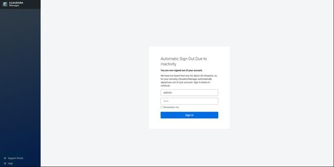
2. Upload license file. Click Continue after successfully uploading license for CDP PvC Base.
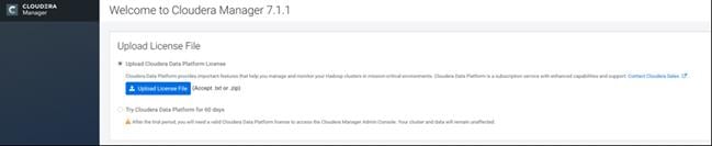
3. Click Continue on the Welcome screen.
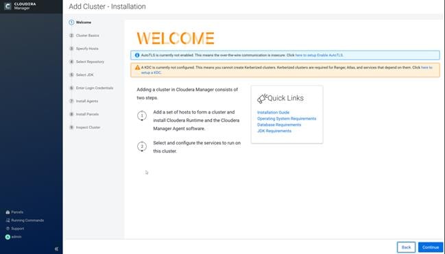
4. Enter name for the Cluster.
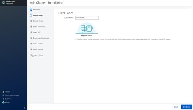
5. Specify the hosts that are part of the cluster using their IP addresses or hostname. The figure below shows a pattern that specifies the IP addresses range.
10.14.1.[45-47] or rhelnn[01-03].cdip.cisco.local
10.14.1.[51-66] or rhel[01-16].cdip.cisco.local
6. After the IP addresses or hostnames are entered, click Search.
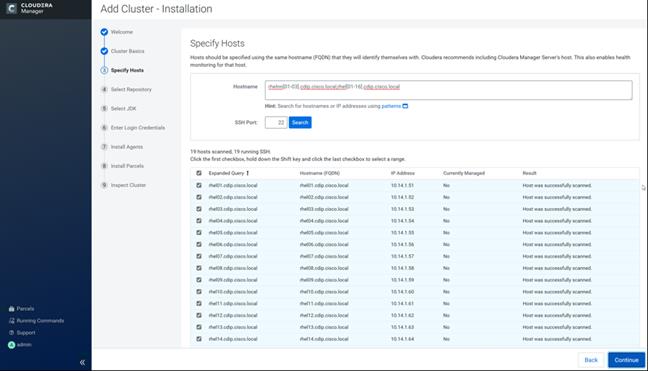
7. Cloudera Manager will "discover" the nodes in the cluster. Verify that all desired nodes have been found and selected for installation.
Edit the Cloudera Data Platform Private Cloud Base Parcel Settings to use the CDP 7.1.1 Parcels
To edit the CDP PvC Base Parcel settings, follow these steps:
1. Add custom repository path for Cloudera Manager local repository created.
2. On the Cloudera Manager installation wizard, click Parcels.
3. Click Parcel Repositories and Network Settings.
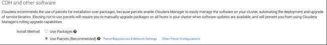
4. Click to remove the entire remote repository URLs and add the URL to the location where we kept the CDP PvC Base 7.1.1 parcels, such as http://10.14.1.46/cloudera-repos/cdh7/7.1.1.0/parcels/
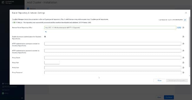
5. Click Save Changes to finish the configuration.
6. Click Continue on the confirmation page.
7. For the method of installation, select the Use Parcels (Recommended) radio button.
8. For the CDP PvC Base 7 version, select the Cloudera Runtime 7.1.1-1.cdh7.1.1.p0.3266817 radio button.
9. For the specific release of Cloudera Manager, select the Custom Repository radio button.
10. Enter the URL for the repository within the admin node. http://10.14.1.46/cloudera-repos/cm7 and click Continue.
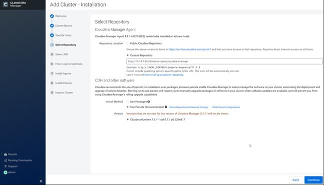
11. Select appropriate option for JDK.
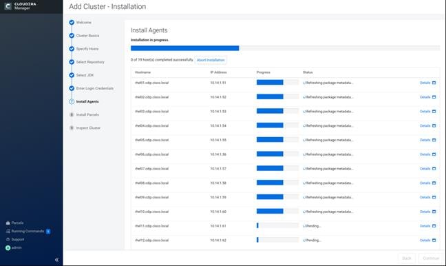
![]() We selected the Manually Manager JDK option as shown in the screenshot (above).
We selected the Manually Manager JDK option as shown in the screenshot (above).
12. Provide SSH login credentials for the cluster and click Continue.
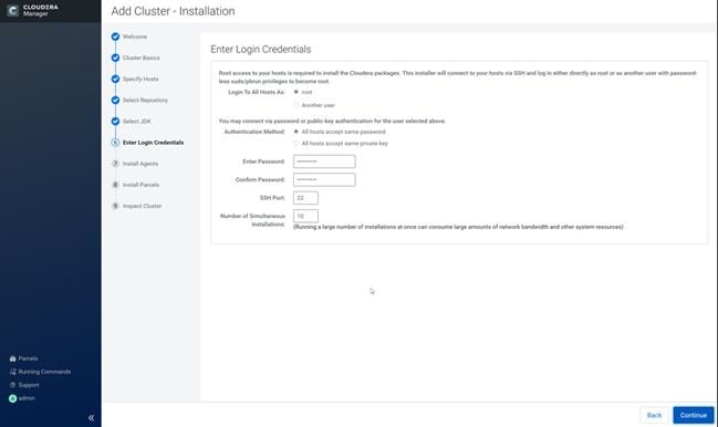
The installation of the local Cloudera repository and using parcels begins.

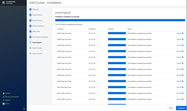

13. Run the inspect the hosts and network performance test through Cloudera Manager on which it has just performed the installation.
14. Review and verify the summary. Click Continue.
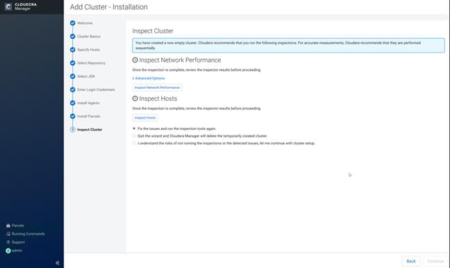

15. Select services that need to be started on the cluster.
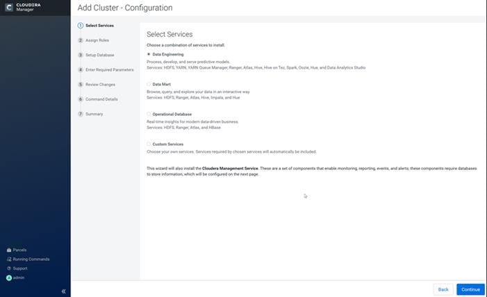
![]() We selected Custom Services for this study.
We selected Custom Services for this study.
16. This is a critical step in the installation: Inspect and customize the role assignments of all the nodes based on your requirements and click Continue.
17. Reconfigure the service assignment to match Table 10.
Table 10 Service/Role Assignment
| Service Name |
Host |
| NameNode |
Rhelnn01, rhelnn02, rhelnn03 (HA) |
| HistoryServer |
rhelnn01 |
| JournalNodes |
rhelnn01, rhelnn02, rhelnn03 |
| ResourceManager |
rhelnn02, rhelnn03 (HA) |
| Hue Server |
rhelnn02 |
| HiveMetastore Server |
rhelnn01 |
| HiveServer2 |
rhelnn02 |
| HBase Master |
rhelnn02 |
| Oozie Server |
rhelnn01 |
| ZooKeeper |
rhelnn01, rhelnn02, rhelnn03 |
| DataNode |
rhel01 to rhel16 |
| NodeManager |
rhel01 to rhel16 |
| RegionServer |
rhel01 to rhel16 |
| Sqoop Server |
rhelnn01 |
| Impala Catalog Server Daemon |
rhelnn01 |
| Impala State Store |
rhelnn02 |
| Impala Daemon |
rhel01 to rhel16 |
| Solr Server |
rhel01 (can be installed on all hosts if needed if there is a search use case) |
| Spark History Server |
rhelnn01 |
| Spark Executors |
rhel01 to rhel16 |
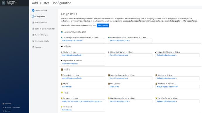
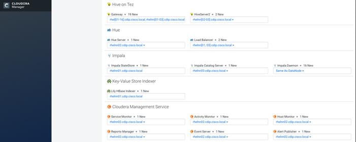

The role assignment recommendation above is for clusters of up to 64 servers. For clusters larger than 64 nodes, use the high availability recommendation defined in Table 9.
To set up the database, follow these steps:
1. In the Database Host Name sections use port 3306 for TCP/IP because connection to the remote server always uses TCP/IP.
2. Enter the Database Name, username and password that were used during the database creation stage earlier in this document.
3. Click Test Connection to verify the connection and click Continue.
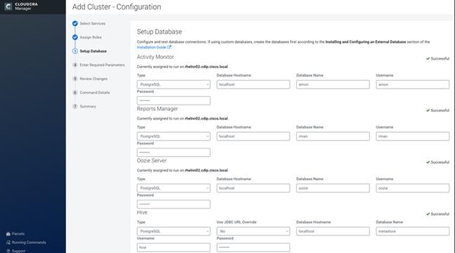
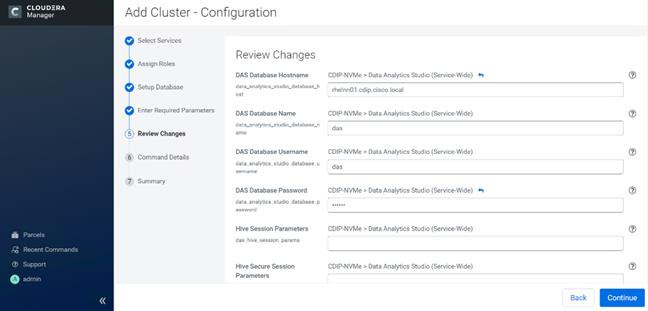
4. Enter required parameters for Data Analytics Studio.
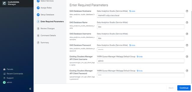
5. Review Data Analytics Studio (DAS) configuration.

6. Review Data Analytics Studio (DAS) configuration.

7. Review and customize the configuration changes based on your requirements.
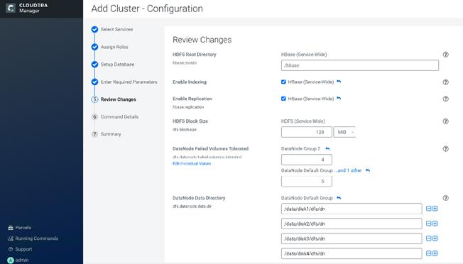
8. Click Continue to start running the cluster services.
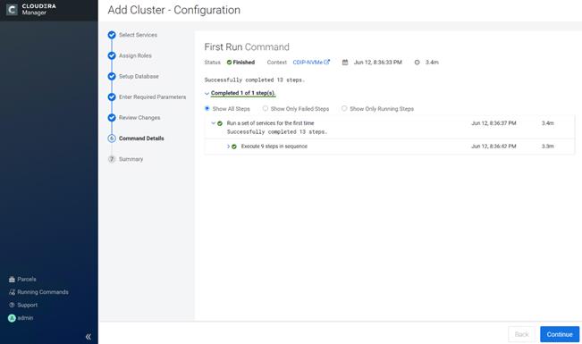
9. Hadoop services are installed, configured, and now running on all the nodes of the cluster. Click Finish to complete the installation.
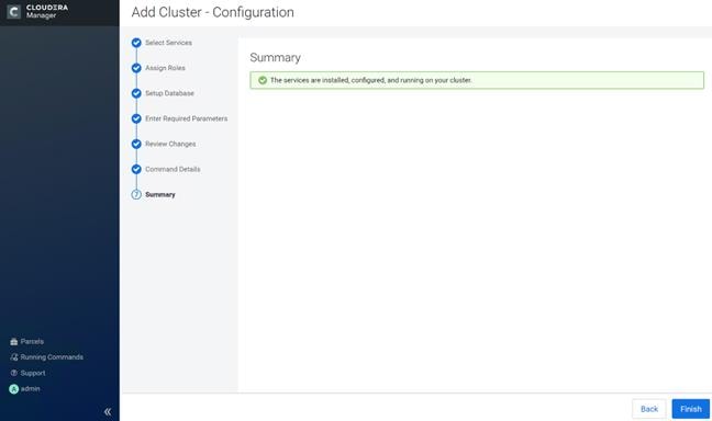
Cloudera Manager now displays the status of all Hadoop services running on the cluster.
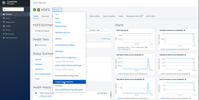
Configure NVMe as YARN Local Directory
To configure YARN local directory on separate NVMe disks, follow these steps:
1. Click cluster > YARN > Configuration tab, filter properties for dirs.
2. Modify disk labels specific to NVMe as per the format and partition performed earlier for following properties:
yarn.nodemanager.local-dir
yarn.nodemanager.log-dirs
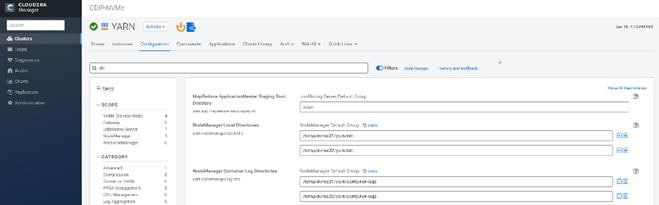
The role assignment recommendation above is for cluster with at least 64 servers and in High Availability. For smaller cluster running without High Availability the recommendation is to dedicate one server for NameNode and a second server for secondary name node and YARN Resource Manager. For larger clusters larger than 28 nodes the recommendation is to dedicate one server each for name node, YARN Resource Manager and one more for running both NameNode (High Availability) and Resource Manager (High Availability) as in the table (no Secondary NameNode when in High Availability).
![]() For production clusters, it is recommended to set up NameNode and Resource manager in High Availability mode.
For production clusters, it is recommended to set up NameNode and Resource manager in High Availability mode.
This implies that there will be at least 3 master nodes, running the NameNode, YARN Resource manager, the failover counterpart being designated to run on another node and a third node that would have similar capacity as the other two nodes.
All the three nodes will also need to run zookeeper and quorum journal node services. It is also recommended to have a minimum of 7 DataNodes in a cluster. Please refer to the next section for details on how to enable HA.
![]() Setting up high availability is done after the Cloudera Installation is completed.
Setting up high availability is done after the Cloudera Installation is completed.
The HDFS High Availability feature provides the option of running two NameNodes in the same cluster, in an Active/standby configuration. These are referred to as the Active NameNode and the Standby NameNode. Unlike the Secondary NameNode, the Standby NameNode is a hot standby, allowing a fast failover to a new NameNode in case that a machine crashes, or a graceful administrator-initiated failover for the purpose of planned maintenance. There cannot be more than two NameNodes.
For more information go to: https://docs.cloudera.com/cdp-private-cloud-base/7.1.3/fault-tolerance/topics/cr-configuring-namenode-high-availability.html
Set Up HDFS High Availability
The Enable High Availability workflow leads through adding a second (standby) NameNode and configuring JournalNodes. During the workflow, Cloudera Manager creates a federated namespace. To set up HDFS High Availability, follow these steps:
1. Log into the admin node (rhelnn01) and create the Edit directory for the JournalNode:
# ansible namenodes -m shell -a "mkdir -p /data/disk1/namenode-edits"
# ansible namenodes -m shell -a "chmod 77 /data/disk1/namenode-edits"
2. Log into the Cloudera manager and go to the HDFS service.
3. Select Actions> Enable High Availability. The hosts that are eligible to run a standby NameNode and the JournalNodes displays.

4. Specify a name for the nameservice or accept the default name nameservice1 and click Continue.
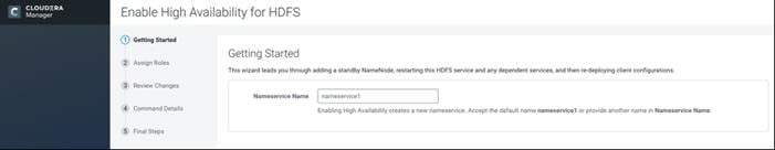
5. In the NameNode Hosts field, click Select a host. The host selection dialog displays.
6. Check the checkbox next to the hosts (rhelnn01) where the standby NameNode is to be set up and click OK.
7. In the JournalNode Hosts field, click Select hosts. The host selection dialog displays.
8. Check the checkboxes next to an odd number of hosts (a minimum of three) to act as JournalNodes and click OK. We used the same nodes for the Zookeeper nodes.
9. Click Continue.
![]() The standby NameNode cannot be on the same host as the active NameNode, and the host that is chosen should have the same hardware configuration (RAM, disk space, number of cores, and so on) as the active NameNode.
The standby NameNode cannot be on the same host as the active NameNode, and the host that is chosen should have the same hardware configuration (RAM, disk space, number of cores, and so on) as the active NameNode.
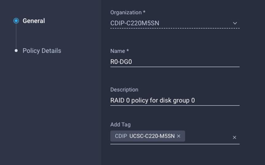
10. In the JournalNode Edits Directory property, enter a directory location created earlier in step 1 for the JournalNode edits directory into the fields for each JournalNode host.
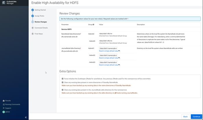
![]() The directories specified should be empty and must have the appropriate permissions.
The directories specified should be empty and must have the appropriate permissions.
11. Extra Options: Decide whether Cloudera Manager should clear existing data in ZooKeeper, Standby NameNode, and JournalNodes. If the directories are not empty (for example, re-enabling a previous HA configuration), Cloudera Manager will not automatically delete the contents—select to delete the contents by keeping the default checkbox selection. The recommended default is to clear the directories.
12. If you choose not to configure any of the extra options, the data should be in sync across the edits directories of the JournalNodes and should have the same version data as the NameNodes.
13. Click Continue.
Cloudera Manager executes a set of commands that will stop the dependent services, delete, create, and configure roles and directories as appropriate, create a nameservice and failover controller, and restart the dependent services and deploy the new client configuration.
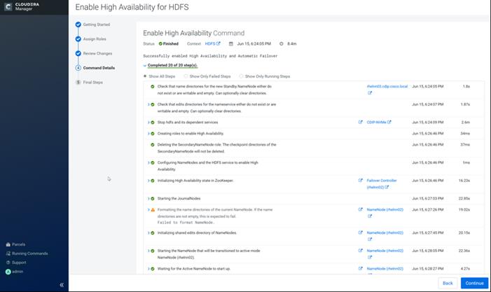
![]() Formatting the name directory is expected to fail if the directories are not empty.
Formatting the name directory is expected to fail if the directories are not empty.
14. In the next screen additional steps are suggested by the Cloudera Manager to update the Hue and Hive metastore. Click Finish.
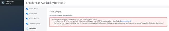
The following sections explain configuring Hue and Hive for high availability as needed.
Configure Hive Metastore to use HDFS High Availability
To configure the Hive Megastore to use HDFS High Availability, follow these steps:
1. Go the Hive service.
2. Select Actions > Stop.
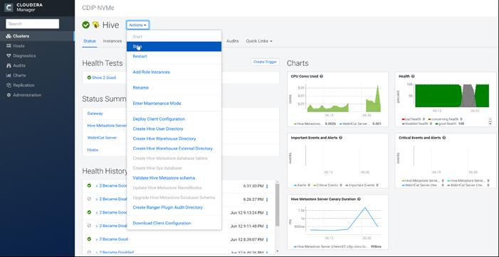
3. Click Stop to confirm the command.
4. Back up the Hive Metastore Database (if any existing data is present).
5. Select Actions > Update Hive Metastore NameNodes and confirm the command.
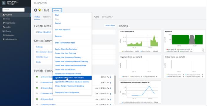
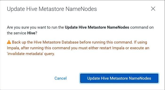
6. Select Actions > Start.
7. Restart the Hue and Impala services if stopped prior to updating the Metastore.
Configure Hue to Work with HDFS High Availability
To configure Hue to work with HDFS High Availability, follow these steps:
1. Go to the HDFS service.
2. Click the Instances tab.
3. Click Add Role Instances.
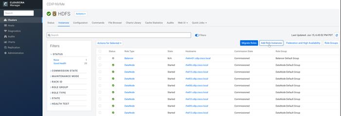
4. Select the text box below the HttpFS field. The Select Hosts dialog displays.
5. Select the host on which to run the role and click OK.
6. Click Continue.
7. Check the checkbox next to the HttpFS role and select Actions for Selected > Start.
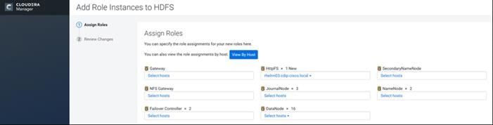
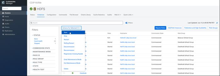
8. After the command has completed, go to the Hue service.
9. Click the Configuration tab.
10. Locate the HDFS Web Interface Role property or search for it by typing its name in the Search box.
11. Select the HttpFS role that was just created instead of the NameNode role and save your changes.
12. Restart the Hue service.

![]() Refer to the high availability section in the Cloudera Management document: https://www.cloudera.com/documentation/enterprise/6/6.2/topics/admin_ha.html for more information on setting up high availability for other components like Impala, Oozie, and so on.
Refer to the high availability section in the Cloudera Management document: https://www.cloudera.com/documentation/enterprise/6/6.2/topics/admin_ha.html for more information on setting up high availability for other components like Impala, Oozie, and so on.
The YARN Resource Manager (RM) is responsible for tracking the resources in a cluster and scheduling applications (for example, MapReduce jobs). Before CDH 5, the RM was a single point of failure in a YARN cluster. The RM high availability (HA) feature adds redundancy in the form of an Active/Standby RM pair to remove this single point of failure. Furthermore, upon failover from the Standby RM to the Active, the applications can resume from their last check-pointed state; for example, completed map tasks in a MapReduce job are not re-run on a subsequent attempt. This allows events such the following to be handled without any significant performance effect on running applications.
● Unplanned events such as machine crashes.
● Planned maintenance events such as software or hardware upgrades on the machine running the ResourceManager.
For more information, go to: https://docs.cloudera.com/cdp-private-cloud-base/7.1.3/yarn-high-availability/topics/yarn-configuring-resourcemanager-ha.html
Set Up YARN High Availability
To set up YARN high availability, follow these steps:
1. Log into the Cloudera manager and go to the YARN service.
2. Select Actions > Enable High Availability.
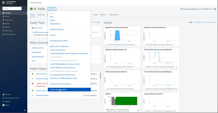
The hosts that are eligible to run a standby ResourceManager displays.
The host where the current ResourceManager is running is not available as a choice.
3. Select the host (rhelnn03) where the standby ResourceManager is to be installed and click Continue.
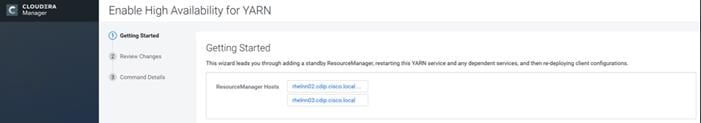
Cloudera Manager proceeds to execute a set of commands that stop the YARN service, add a standby ResourceManager, initialize the ResourceManager high availability state in ZooKeeper, restart YARN, and rede-ploy the relevant client configurations.
4. Click Finish when the installation is completed successfully.
Configure Yarn (MR2 Included) and HDFS Services
The parameters in Table 11 and Table 12 are used for Cisco UCS Integrated Infrastructure for Big Data and Analytics Performance Optimized cluster configuration described in this document. These parameters are to be changed based on the cluster configuration, number of nodes and specific workload.
| Service |
Value |
| mapreduce.output.fileoutputformat.compress.type |
BLOCK |
| mapreduce.output.fileoutputformat.compress.codec |
org.apache.hadoop.io.compress.DefaultCodec |
| mapreduce.map.output.compress.codec |
org.apache.hadoop.io.compress.SnappyCodec |
| mapreduce.map.output.compress |
True |
| zlib.compress.level |
BEST_SPEED |
| mapreduce.task.io.sort.factor |
64 |
| mapreduce.map.sort.spill.percent |
0.9 |
| mapreduce.reduce.shuffle.parallelcopies |
20 |
| yarn.nodemanager.resource.memory-mb |
320GB |
| yarn.nodemanager.resource.cpu-vcores |
64 |
| yarn.scheduler.maximum-allocation-vcores |
64 |
| yarn.scheduler.maximum-allocation-mb |
320GB |
| mapreduce.task.io.sort.mb |
2047 |
| mapreduce.job.reduce.slowstart.completedmap |
0.8 |
| yarn.app.mapreduce.am.resource.cpu-vcores |
1 |
| mapreduce.map.memory.mb |
5G |
| mapreduce.reduce.memory.mb |
5G |
| mapreduce.job.heap.memory-mb.ratio |
0.8 |
| mapreduce.job.shuffle.merge.percent |
0.95 |
| mapreduce.job.shuffle.input.buffer.percent |
0.7 |
| mapreduce.job.reduce.input.buffer.percent |
0.7 |
| mapreduce.input.fileinputformat.split.minsize |
4096000000 |
| mapreduce.ifile.readahead.bytes |
16777216 |
| mapreduce.inmem.merge.threshold |
0 |
| Enable Optimized Map-side Output Collector |
Enable – Gateway Default Group |
| Service |
Value |
| dfs.datanode.failed.volumes.tolerated |
4 |
| dfs.datanode.du.reserved |
50 GiB |
| dfs.datanode.data.dir.perm |
755 |
| Java Heap Size of Namenode in Bytes |
4096 MiB (Could not change since minimum 1GB recommended) |
| Java Heap Size of Secondary namenode in Bytes |
4096 MiB (Could not change since minimum 1GB recommended) |
| dfs.namenode.handler.count |
55 |
| dfs.namenode.service.handler.count |
55 |
The two main resources that Spark (and YARN) are dependent on are CPU and memory. Disk and network I/O play a part in Spark performance as well, but neither Spark nor YARN currently can actively manage them. Every Spark executor in any application has the same fixed number of cores and same fixed heap size. The number of cores can be specified with the executor-cores flag when invoking spark-submit, spark-shell, and pyspark from the command line, or by setting the spark.executor.cores property in the spark-defaults.conf file or in the SparkConf object.
The heap size can be controlled with the executor-memory flag or the spark.executor.memory property. The cores property controls the number of concurrent tasks an executor can run, executor-cores = 5 mean that each executor can run a maximum of five tasks at the same time. The memory property impacts the amount of data Spark can cache, as well as the maximum sizes of the shuffle data structures used for grouping, aggregations, and joins.
The num-executors command-line flag or spark.executor.instances configuration property control the number of executors requested. Dynamic Allocation can be enabled from CDH5.4 instead setting the spark.dynamicAllocation.enabled to true. Dynamic allocation enables a Spark application to request executors when there is a backlog of pending tasks and free up executors when idle.
Asking for five executor cores will result in a request to YARN for five virtual cores. The memory requested from YARN is a little more complex for the following reasons:
● executor-memory/spark.executor.memory controls the executor heap size, but JVMs can also use some memory off heap, for example for VM overhead, interned Strings and direct byte buffers. The value of the spark.yarn.executor.memoryOverhead property is added to the executor memory to determine the full memory request to YARN for each executor. It defaults to max (384, 0.10 * spark.executor.memory).
● YARN may round the requested memory up a little. YARN’s yarn.scheduler.minimum-allocation-mb and yarn.scheduler.increment-allocation-mb properties control the minimum and increment request values respectively.
The application master is a non-executor container with the special capability of requesting containers from YARN, takes up resources of its own that must be budgeted in. In yarn-client mode, it defaults to a 1024MB and one vcore. In yarn-cluster mode, the application master runs the driver, so it’s often useful to add its resources with the –driver-memory and –driver-cores properties.
Running executors with too much memory often results in excessive garbage collection delays. 64GB is a rough guess at a good upper limit for a single executor.
A good estimate is that at most five tasks per executor can achieve full write throughput, so it’s good to keep the number of cores per executor around that number.
Running tiny executors (with a single core and just enough memory needed to run a single task, for example) throws away the benefits that come from running multiple tasks in a single JVM. For example, broadcast variables need to be replicated once on each executor, so many small executors will result in many more copies of the data.
Tune Resource Allocation for Spark
● Below is an example of configuring a Spark application to use as much of the cluster as possible, we are using an example cluster with 16 nodes running NodeManagers, each equipped with 56 cores and 256GB of memory. yarn.nodemanager.resource.memory-mb and yarn.nodemanager. resource.cpu-vcores should be set to 180 * 1024 = 184320 (megabytes) and 48 respectively.
spark.default.parallelism=10000
spark.driver.memoryOverhead=4096
spark.executor.memoryOverhead=4096
spark.executor.extraJavaOptions=-XX:+UseParallelGC -XX:ParallelGCThreads=4
spark.shuffle.file.buffer=1024k
spark.broadcast.compress=true
spark.shuffle.compress=true
spark.io.compression.codec=org.apache.spark.io.SnappyCompressionCodec
spark.io.compression.snappy.blockSize=512k
● This configuration results in four executors on all nodes except for the one with the AM, which will have three executors.
executor-memory is derived as (180/4 executors per node) = 45; 45 * 0.10 = 4.5 45 – 4.5 ~ 40.
For taking care of long running processes use 2G for the spark driver
spark.driver.memory = 2G
--driver -memory 2G –executor -memory 40G --num-executors 63 --executor-cores 5 --properties-file /opt/cloudera/parcels/CDH/etc/spark/conf.dist/spark-defaults.conf
In yarn-cluster mode, the local directories used by the Spark executors and the Spark driver will be the local directories configured for YARN (Hadoop YARN config yarn.nodemanager.local-dirs). If the user specifies spark.local.dir, it will be ignored.
In yarn-client mode, the Spark executors will use the local directories configured for YARN while the Spark driver will use those defined in spark.local.dir. The Spark driver does not run on the YARN cluster in yarn-client mode, only the Spark executors do.
spark.local.dir /tmp (Directory to use for "scratch" space in Spark, including map output files and RDDs that get stored on disk. This should be on a fast, local disk in your system).
Every Spark stage has several tasks, each of which processes data sequentially. In tuning Spark jobs, this parallelism number is the most important parameter in determining performance. The number of tasks in a stage is the same as the number of partitions in the last RDD in the stage. The number of partitions in an RDD is the same as the number of partitions in the RDD on which it depends, with a couple exceptions: the coalesce transformation allows creating an RDD with fewer partitions than its parent RDD, the union transformation creates an RDD with the sum of its parents’ number of partitions, and Cartesian creates an RDD with their product.
RDDs produced by a file have their partitions determined by the underlying MapReduce InputFormat that’s used. Typically there will be a partition for each HDFS block being read. Partitions for RDDs produced by parallelize come from the parameter given by the user, or spark.default.parallelism if none is given.
The primary concern is that the number of tasks will be too small. If there are fewer tasks than slots available to run them in, the stage won’t be taking advantage of all the CPU available.
If the stage in question is reading from Hadoop, your options are:
● Use the repartition transformation, which will trigger a shuffle.
● Configure your InputFormat to create more splits.
● Write the input data out to HDFS with a smaller block size.
If the stage is getting its input from another stage, the transformation that triggered the stage boundary will accept a numPartitions argument.
The most straightforward way to tune the number of partitions is experimentation: Look at the number of partitions in the parent RDD and then keep multiplying that by 1.5 until performance stops improving.
In contrast with MapReduce for Spark when in doubt, it is almost always better to be on the side of a larger number of tasks (and thus partitions).
Shuffle Performance Improvement
spark.shuffle.compress true (compress map output files)
spark.broadcast.compress true (compress broadcast variables before sending them)
spark.io.compression.codec org.apache.spark.io.SnappyCompressionCodec (codec used to compress internal data such as RDD partitions, broadcast variables and shuffle outputs)
spark.shuffle.spill.compress true (Whether to compress data spilled during shuffles.)
spark.shuffle.io.numConnectionsPerPeer 4 (Connections between hosts are reused in order to reduce connection buildup for large clusters. For clusters with many hard disks and few hosts, this may result in insufficient concurrency to saturate all disks, and so users may consider increasing this value.)
spark.shuffle.file.buffer 64K (Size of the in-memory buffer for each shuffle file output stream. These buffers reduce the number of disk seeks and system calls made in creating intermediate shuffle file)
Improve Serialization Performance
Serialization plays an important role in the performance of any distributed application. Often, this will be the first thing that should be tuned to optimize a Spark application.
spark.serializer org.apache.spark.serializer.KryoSerializer (when speed is necessary)
spark.kryo.referenceTracking false
spark.kryoserializer.buffer 2000 (If the objects are large, may need to increase the size further to fit the size of the object being deserialized).
SparkSQL is ideally suited for mixed procedure jobs where SQL code is combined with Scala, Java, or Python programs. In general, the SparkSQL command line interface is used for single user operations and ad hoc queries.
For multi-user SparkSQL environments, it is recommended to use a Thrift server connected via JDBC.
The guidelines for Spark SQL tuning are as follows:
● To compile each query to Java bytecode on the fly, turn on sql.codegen. This can improve performance for large queries but can slow down very short queries:
spark.sql.codegen true
spark.sql.unsafe.enabled true
● Configuration of in-memory caching can be done using the setConf method on SQLContext or by running SET key=value commands using SQL.
● spark.sql.inMemoryColumnarStorage.compressed true (will automatically select a compression codec for each column based on statistics of the data)
● spark.sql.inMemoryColumnarStorage.batchSize 5000 (Controls the size of batches for columnar caching. Larger batch sizes can improve memory utilization and compression, but risk OOMs when caching data)
● The columnar nature of the ORC format helps avoid reading unnecessary columns, but it is still possible to read unnecessary rows. ORC avoids this type of overhead by using predicate push-down with three levels of built-in indexes within each file: file level, stripe level, and row level. This combination of indexed data and columnar storage reduces disk I/O significantly, especially for larger datasets where I/O bandwidth becomes the main bottleneck for performance.
● By default, ORC predicate push-down is disabled in Spark SQL. To obtain performance benefits from predicate push-down, enable it explicitly, as follows:
spark.sql.orc.filterPushdown=true
● In SparkSQL to automatically determine the number of reducers for joins and groupbys, use the parameter:
spark.sql.shuffle.partitions 200, (default value is 200)
● This property can be put into hive-site.xml to override the default value.
● Set log to WARN in log4j.properties to reduce log level.
![]() Running the Thrift server and connecting to spark-sql through beeline is the recommended option for multi-session testing.
Running the Thrift server and connecting to spark-sql through beeline is the recommended option for multi-session testing.
Set the following Hive parameters to compress the Hive output files using Snappy compression:
hive.exec.compress.output=true
hive.exec.orc.default.compress=SNAPPY
Change the Log Directory for All Applications
To change the default log from the /var prefix to /data/disk1, follow these steps:
1. Log into the cloudera home page and click My Clusters.
2. From the configuration drop-down list select “All Log Directories.”
3. Click Save.
All NVMe PCIe based storage for Big Data and Analytics solution for various AI/ML workload and multiple applications which could scale to thousands of nodes and operational efficiency can’t be an afterthought.
NVMe storage helps us achieve fast and parallel access to data reducing idle time for GPU and able to utilize resource in much more efficient way while reducing TCO by minimizing required hardware which saves in overall rack space, power, and cooling in the datacenter.
To achieve a seamless operation of the application at this scale, you need the following:
● Infrastructure automation of Cisco UCS servers with service profiles and Cisco Data Center network automation with application profiles with Cisco ACI.
● Centralized Management and Deep telemetry and Simplified granular trouble-shooting capabilities and • Multi-tenancy allowing application workloads including containers, micro-services, with the right level of security and SLA for each workload.
● Cisco UCS with Cisco Intersight and Cisco ACI can enable this cloud scale architecture deployed and managed with ease.
● CDP on CIDP delivers new approach to data where machine learning intelligently auto scale workloads up and down for more cost-effective use of private cloud infrastructure.
For additional information, see the following resources:
● To find out more about Cisco UCS big data solutions, see http://www.cisco.com/go/bigdata.
● To find out more about Cisco Data Intelligence Platform, see https://www.cisco.com/c/dam/en/us/products/servers-unified-computing/ucs-c-series-rack-servers/solution-overview-c22-742432.pdf
● To find out more about Cisco UCS big data validated designs, see http://www.cisco.com/go/bigdata_design
● To find out more about Cisco UCS AI/ML solutions, see http://www.cisco.com/go/ai-compute
● To find out more about Cisco ACI solutions, see http://www.cisco.com/go/aci
● To find out more about Cisco validated solutions based on Software Defined Storage, see https://www.cisco.com/c/en/us/solutions/data-center-virtualization/software-defined-storage-solutions/index.html
● Cloudera Data Platform Private Cloud Base 7.1.1 release note, see https://docs.cloudera.com/runtime/7.1.1/release-notes/index.html
● CDP Private Cloud Base Requirements and Supported Versions, see https://docs.cloudera.com/cdp-private-cloud-base/7.1.3/installation/topics/cdpdc-requirements-supported-versions.html
This section provides the bill of materials for the 28 Nodes Hadoop Base Rack. See Table 13 for the bill of materials for the Hadoop Base rack and Table 14 for Red Hat Enterprise Linux License.
Table 13 Bill of Materials for Cisco UCS C240 M5SX Hadoop Nodes Base Rack
| Part Number |
Description |
Quantity |
| UCSC-C220-M5SN |
Cisco UCS C220 M5 SFF 10 NVMe w/o CPU, mem, HD, PCIe, PSU |
16 |
| CON-SNT-C220M5SN |
SNTC 8X5XNBD UCS C220 M5 SFF NVMe 10 HD w/o CPU, mem, HD, PC |
16 |
| UCS-MR-X32G2RT-H |
32GB DDR4-2933-MHz RDIMM/2Rx4/1.2v |
192 |
| UCSC-NVMEHW-I8000 |
8TB 2.5in U.2 Intel P4510 NVMe High Perf. Value Endurance |
160 |
| UCSC-MLOM-C40Q-03 |
Cisco VIC 1387 Dual Port 40Gb QSFP CNA MLOM |
16 |
| UCS-M2-240GB |
240GB SATA M.2 |
32 |
| UCS-M2-HWRAID |
Cisco Boot optimized M.2 Raid controller |
16 |
| CIMC-LATEST |
IMC SW (Recommended) latest release for C-Series Servers. |
16 |
| UCSC-PSU1-1050W |
Cisco UCS 1050W AC Power Supply for Rack Server |
32 |
| CAB-N5K6A-NA |
Power Cord, 200/240V 6A North America |
32 |
| UCSC-RAILB-M4 |
Ball Bearing Rail Kit for C220 & C240 M4 & M5 rack servers |
16 |
| UCS-SID-INFR-BD |
Big Data and Analytics Platform (Hadoop/IoT/ITOA/AI/ML) |
16 |
| UCS-SID-WKL-BD |
Big Data and Analytics (Hadoop/IoT/ITOA) |
16 |
| UCSC-HS-C220M5 |
Heat sink for UCS C220 M5 rack servers 150W CPUs & below |
32 |
| UCS-CPU-I6230R |
Intel 6230R 2.1GHz/150W 26C/ 35MB DCP DDR4 2933 MHz |
32 |
| RHEL-2S2V-3A |
Red Hat Enterprise Linux (1-2 CPU,1-2 VN); 3-Yr Support Req |
16 |
| CON-ISV1-EL2S2V3A |
ISV 24X7 RHEL Server 2Socket-OR-2Virtual; ANNUAL List Price |
16 |
| RACK2-UCS2 |
Cisco R42612 standard rack, w/side panels |
2 |
| CON-SNT-RCK2UCS2 |
SNTC 8X5XNBD, Cisco R42612 standard rack, w side panels |
2 |
Table 14 Red Hat Enterprise Linux License
| Part Number |
Description |
Quantity |
| RHEL-2S2V-3A |
Red Hat Enterprise Linux |
30 |
| CON-ISV1-EL2S2V3A |
3-year Support for Red Hat Enterprise Linux |
30 |
![]() For Cloudera Data Platform Private Cloud Base (CDP PvC Base) software licensing requirement, contact Cloudera Data Platform software - Sales
For Cloudera Data Platform Private Cloud Base (CDP PvC Base) software licensing requirement, contact Cloudera Data Platform software - Sales
Storage Policy in Intersight for Data Nodes
To create a storage policy and server policy for a data node with RAID Controller (UCSC-RAID-M5 or UCSC-RAID-M5HD) with each disk configured in RAID 0, follow these steps:
1. In Cisco Intersight, click Policies. Select Disk Group.
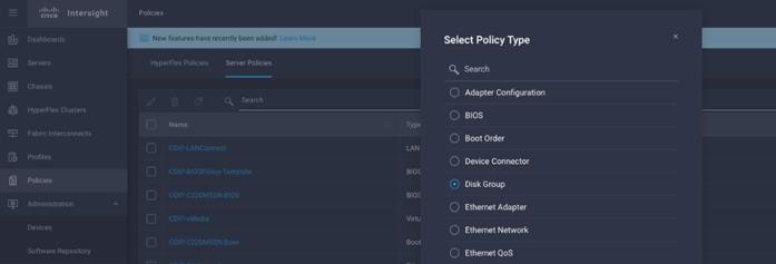
2. Enter the Organization, Name, Description and create a new tag or assign an existing tag. Click Next.
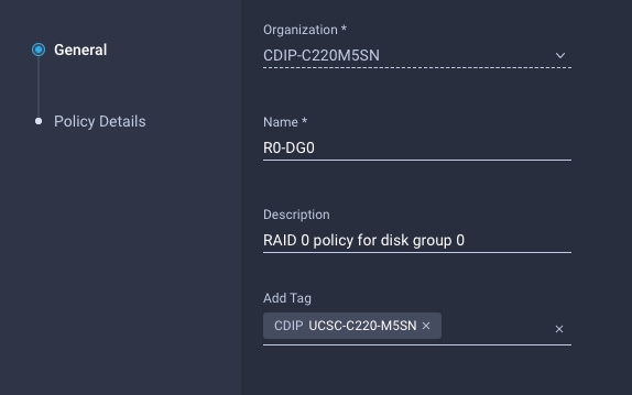
3. Select RAID Level as RAID0. In Local Disk Configuration for Disk Group (Span 0) and enter Slot Number 1.
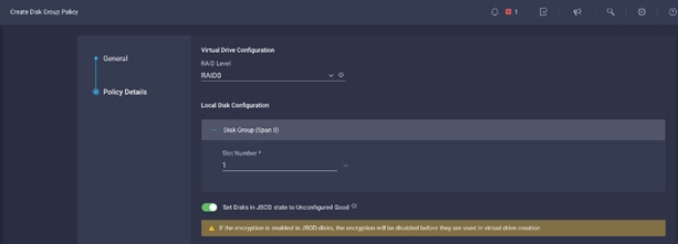
4. Repeat steps 1-3 to create Disk Group for disks installed in slot 1-10, for example C240 M5 with 26 disks will require creation of 26 Disk groups and associate disk to each Disk Group.
5. Select Storage in Create Server Policy.

6. Select RAID Level as RAID0. In Local Disk Configuration for Disk Group (Span 0) and enter Slot Number 1.
7. Repeat steps 1-3 to create Disk Group for disks installed in slot 1-10, for example C240 M5 with 26 disks will require creation of 26 Disk groups and associate disk to each Disk Group.
8. Select Storage in Create Server Policy.
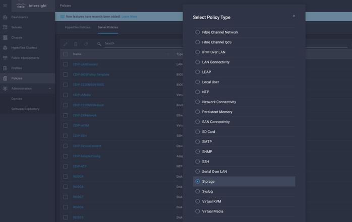
9. Click Create to complete Storage Policy creation for Data Nodes with each disk as RAID0.
Cisco UCS Rack Server Firmware Upgrade from Intersight
A firmware upgrade can be performed via remote HUU (Host Upgrade Utility) ISO file mounted to Cisco IMC via NFS/CIFS/HTTP/HTTPS protocols or the server firmware can be upgraded through Utility Storage.
![]() Booting HUU from Cisco FlexUtil on Cisco UCS M5 servers and Cisco FlexFlash in Util mode on Cisco UCS M4 servers.
Booting HUU from Cisco FlexUtil on Cisco UCS M5 servers and Cisco FlexFlash in Util mode on Cisco UCS M4 servers.
To upgrade from Intersight, follow these steps:
1. From Intersight web UI console, go to Servers tab. Select server(s). Right-click and select Upgrade Firmware.
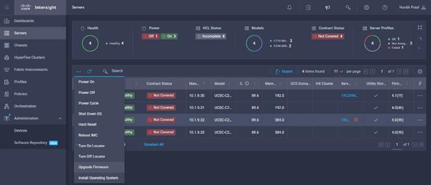
2. Select the Utility Storage tab and from the drop-down list select the firmware version. Click Upgrade Firmware.
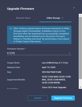
3. Monitor upgrade process from the active list of task.
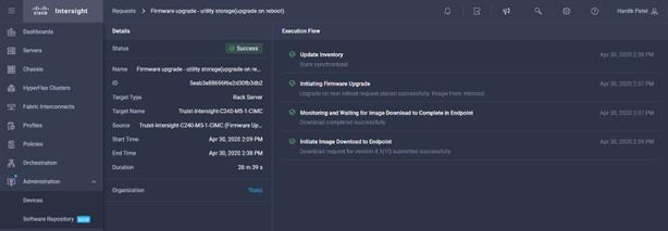
Once HUU ISO image is downloaded to local endpoint, the upgrade process starts after performing a Power Cycle or Host Reboot on the server, HUU is booted and upgrade begins on the server.

Upgrade process can be monitor from the list of active task.

Configure Cisco Nexus and Host for Active-Active Connections
Port Configuration on Cisco Nexus 9332C
Table 15 lists the port configuration on Cisco UCS Nexus 9000 series switch.
Table 15 Port Configuration on Cisco UCS Nexus Switch
| Port Type |
Port Number |
| vPC Peer-Link |
1-4 (for LACP) |
| Network Uplink from C220 M5 to Nexus 9332C Switch |
5-20 |
| Network Uplink from Cisco Nexus 9332C to Nexus 9504 |
21-32 |
Configure vPC Domain and vPC Peer-Link on Pair of Cisco Nexus Switch
To configure Nexus A, follow these steps:
1. Connect to the console port or management port on the first Cisco Nexus 9332C-A. Complete the initial setup.
2. Enable feature VPC and configure VPC domain.
# config terminal
# feature vpc
# feature lacp
# vpc domain 100
# peer-keepalive destination 173.37.52.67 source 173.37.52.66
# exit
![]() Enable feature lacp for mode 4 based bond configuration.
Enable feature lacp for mode 4 based bond configuration.
3. Connect to the console port or management port on the second Cisco Nexus 9332C-B.
4. Enable feature VPC and configure VPC domain. Configure peer nexus for keep alive.
# config terminal
# feature vpc
# feature lacp
# vpc domain 100
# peer-keepalive destination 173.37.52.66 source 173.37.52.67
# exit
5. On both Nexus Switch, create interface port channel (we use 100 here for example), for VPC peer link. Configure the port channel for allowed VLAN (VLAN 14 in the example below).
# interface port-channel100
# description vpc-peerlink
# switchport mode trunk
# switchport trunk allowed vlan 14
# spanning-tree port type network
# vpc-peer-link
6. Configure the interconnected ports on both Nexus switches and add them in port-channel 100 created for vPC-peerlink.
# interface Ethernet1/1
# switchport mode trunk
# switchport trunk allowed vlan 14
# spanning-tree port type network
# channel-group 100
# no shutdown
# interface Ethernet1/2
# switchport mode trunk
# switchport trunk allowed vlan 14
# spanning-tree port type network
# channel-group 100
# no shutdown
# interface Ethernet1/3
# switchport mode trunk
# switchport trunk allowed vlan 14
# spanning-tree port type network
# channel-group 100
# no shutdown
# interface Ethernet1/4
# switchport mode trunk
# switchport trunk allowed vlan 14
# spanning-tree port type network
# channel-group 100
# no shutdown
7. Configure the ethernet interfaces on both Nexus switches to be part of port channels connected to northbound switch in spine-leaf architecture or ToR switch. Ports 1 through 6 and 27 through 32 were configured part of interface port-channel 50.
interface port-channel50
description NB_ToR_N9K
switchport mode trunk
switchport trunk allowed vlan 14
spanning-tree port type network
mtu 9216
interface Ethernet1/27
description K14-N9K-P19-24
switchport mode trunk
switchport trunk allowed vlan 14
spanning-tree port type network
mtu 9216
channel-group 50 mode active
interface Ethernet1/28
description K14-N9K-P19-24
switchport mode trunk
switchport trunk allowed vlan 14
spanning-tree port type network
mtu 9216
channel-group 50 mode active
8. Create the port-channel between Cisco UCS C220 M5 server VIC interface connected to each Nexus switch. Port 9-24 is configured in the port-channel with the corresponding vpc id for mod 4.
interface port-channel51
description DataNode01
switchport access vlan 14
spanning-tree port type edge
mtu 9216
vpc 51
interface port-channel52
description DataNode02
switchport access vlan 14
spanning-tree port type edge
mtu 9216
vpc 52
interface Ethernet1/9
description Connected to Server DataNode01
switchport access vlan 14
spanning-tree port type edge
mtu 9216
channel-group 51 mode active
interface Ethernet1/10
description Connected to Server DataNode02
switchport access vlan 14
spanning-tree port type edge
mtu 9216
channnel-group 52 mode active
9. Create the port-channel between Cisco UCS C220 M5 server VIC interface connected to each Nexus switch. Port 9-24 is configured in the port-channel.
interface port-channel51
description DataNode01
switchport access vlan 14
spanning-tree port type edge
mtu 9216
vpc 51
interface port-channel52
description DataNode02
switchport access vlan 14
spanning-tree port type edge
mtu 9216
vpc 52
interface Ethernet1/9
description Connected to Server rhel01
switchport access vlan 14
spanning-tree port type edge
mtu 9216
interface Ethernet1/10
description Connected to Server rhel02
switchport access vlan 14
spanning-tree port type edge
mtu 9216
Configure Network and Bond Interfaces for Mode 4
To configure the network and bond interfaces, follow these steps:
1. Setup /etc/sysconfig/ifcfg-bond0. Configure the two VNIC interfaces as slave interfaces to the bond interface.
2. Run the following to configure bond on for each Name Node and Data Node:
[root@rhelnn01 ~]# cat /etc/sysconfig/network-scripts/ifcfg-bond0
DEVICE=bond0
NAME=bond0
TYPE=Bond
BONDING_MASTER=yes
IPADDR=10.14.1.45
NETMASK=255.255.255.0
ONBOOT=yes
HOTPLUG=no
BOOTPROTO=none
USERCTL=no
BONDING_OPTS="miimon=100 mode=4"
NM_CONTROLLED=no
MTU="9000"
[root@rhelnn01 ~]# cat /etc/sysconfig/network-scripts/ifcfg-eno5
TYPE=Ethernet
BOOTPROTO=none
NAME=bond0-slave1
DEVICE=eno5
ONBOOT=no
MASTER=bond0
SLAVE=yes
NM_CONTROLLED=no
HOTPLUG=no
USERCTL=no
MTU="9000"
[root@rhelnn01 ~]# cat /etc/sysconfig/network-scripts/ifcfg-eno6
TYPE=Ethernet
BOOTPROTO=none
NAME=bond0-slave6
DEVICE=eno6
ONBOOT=no
MASTER=bond0
SLAVE=yes
NM_CONTROLLED=no
HOTPLUG=no
USERCTL=no
MTU="9000"
[root@rhelnn01 ~]# ip addr
1: lo: <LOOPBACK,UP,LOWER_UP> mtu 65536 qdisc noqueue state UNKNOWN group default qlen 1000
link/loopback 00:00:00:00:00:00 brd 00:00:00:00:00:00
inet 127.0.0.1/8 scope host lo
valid_lft forever preferred_lft forever
2: eno5: <BROADCAST,MULTICAST,SLAVE,UP,LOWER_UP> mtu 9000 qdisc mq master bond0 state UP group default qlen 1000
link/ether 38:0e:4d:b5:49:d6 brd ff:ff:ff:ff:ff:ff
3: eno6: <BROADCAST,MULTICAST,SLAVE,UP,LOWER_UP> mtu 9000 qdisc mq master bond0 state UP group default qlen 1000
link/ether 38:0e:4d:b5:49:d6 brd ff:ff:ff:ff:ff:ff
4: eno1: <NO-CARRIER,BROADCAST,MULTICAST,UP> mtu 1500 qdisc mq state DOWN group default qlen 1000
link/ether 38:0e:4d:7d:b7:f2 brd ff:ff:ff:ff:ff:ff
5: eno2: <NO-CARRIER,BROADCAST,MULTICAST,UP> mtu 1500 qdisc mq state DOWN group default qlen 1000
link/ether 38:0e:4d:7d:b7:f3 brd ff:ff:ff:ff:ff:ff
6: bond0: <BROADCAST,MULTICAST,MASTER,UP,LOWER_UP> mtu 9000 qdisc noqueue state UP group default qlen 1000
link/ether 38:0e:4d:b5:49:d6 brd ff:ff:ff:ff:ff:ff
inet 10.14.1.45/24 brd 10.14.1.255 scope global bond0
valid_lft forever preferred_lft forever
![]() BONDING_OPTS="miimon=100 mode=4" for link aggregated bond configuration.
BONDING_OPTS="miimon=100 mode=4" for link aggregated bond configuration.
Configure Network and Bond Interfaces for mode 6
To configure the network and bond interfaces, follow these steps:
1. Setup /etc/sysconfig/ifcfg-bond0. Configure the two VNIC interfaces as slave interfaces to the bond interface.
2. Run the following to configure bond on for each Name Node and Data Node:
[root@rhelnn01 ~]# cat /etc/sysconfig/network-scripts/ifcfg-bond0
DEVICE=bond0
NAME=bond0
TYPE=Bond
BONDING_MASTER=yes
IPADDR=10.14.1.45
NETMASK=255.255.255.0
ONBOOT=yes
HOTPLUG=no
BOOTPROTO=none
USERCTL=no
BONDING_OPTS="miimon=100 mode=6"
NM_CONTROLLED=no
MTU="9000"
[root@rhelnn01 ~]# cat /etc/sysconfig/network-scripts/ifcfg-eno5
TYPE=Ethernet
BOOTPROTO=none
NAME=bond0-slave1
DEVICE=eno5
ONBOOT=no
MASTER=bond0
SLAVE=yes
NM_CONTROLLED=no
HOTPLUG=no
USERCTL=no
MTU="9000"
[root@rhelnn01 ~]# cat /etc/sysconfig/network-scripts/ifcfg-eno6
TYPE=Ethernet
BOOTPROTO=none
NAME=bond0-slave6
DEVICE=eno6
ONBOOT=no
MASTER=bond0
SLAVE=yes
NM_CONTROLLED=no
HOTPLUG=no
USERCTL=no
MTU="9000"
[root@rhelnn01 ~]# ip addr
1: lo: <LOOPBACK,UP,LOWER_UP> mtu 65536 qdisc noqueue state UNKNOWN group default qlen 1000
link/loopback 00:00:00:00:00:00 brd 00:00:00:00:00:00
inet 127.0.0.1/8 scope host lo
valid_lft forever preferred_lft forever
2: eno5: <BROADCAST,MULTICAST,SLAVE,UP,LOWER_UP> mtu 9000 qdisc mq master bond0 state UP group default qlen 1000
link/ether 38:0e:4d:b5:49:d6 brd ff:ff:ff:ff:ff:ff
3: eno6: <BROADCAST,MULTICAST,SLAVE,UP,LOWER_UP> mtu 9000 qdisc mq master bond0 state UP group default qlen 1000
link/ether 38:0e:4d:b5:49:d6 brd ff:ff:ff:ff:ff:ff
4: eno1: <NO-CARRIER,BROADCAST,MULTICAST,UP> mtu 1500 qdisc mq state DOWN group default qlen 1000
link/ether 38:0e:4d:7d:b7:f2 brd ff:ff:ff:ff:ff:ff
5: eno2: <NO-CARRIER,BROADCAST,MULTICAST,UP> mtu 1500 qdisc mq state DOWN group default qlen 1000
link/ether 38:0e:4d:7d:b7:f3 brd ff:ff:ff:ff:ff:ff
6: bond0: <BROADCAST,MULTICAST,MASTER,UP,LOWER_UP> mtu 9000 qdisc noqueue state UP group default qlen 1000
link/ether 38:0e:4d:b5:49:d6 brd ff:ff:ff:ff:ff:ff
inet 10.14.1.45/24 brd 10.14.1.255 scope global bond0
valid_lft forever preferred_lft forever
![]() BONDING_OPTS="miimon=100 mode=6" for balanced-alb bond configuration.
BONDING_OPTS="miimon=100 mode=6" for balanced-alb bond configuration.
Sarath Gonugunta, Technical Marketing Engineer, Computing Systems Product Group, Cisco Systems, Inc.
Sarath Gonugunta is a Technical Marketing Engineer in the Cisco Computing Systems Product Group. He is part of the Cisco UCS Solutions Engineering team currently focusing on Big Data infrastructure, solutions, and performance.
Hardik Patel, Technical Marketing Engineer, Computing Systems Product Group, Cisco Systems, Inc.
Hardik Patel is a Big Data Solutions Architect in the Computing Systems Product Group. He is part of the Cisco UCS Solution Engineering team focusing on Big Data infrastructure, solutions, and performance.
For their support and contribution to the design, validation, and creation of this Cisco Validated Design, the authors would like to thank:
● Karthik Kulkarni, Architect, Computing Systems Product Group, Cisco Systems, Inc.
● Muhammad Afzal, Architect, Computing Systems Product Group, Cisco Systems, Inc.