Cisco Catalyst 6807-XL Switch Hardware Installation Guide
Bias-Free Language
The documentation set for this product strives to use bias-free language. For the purposes of this documentation set, bias-free is defined as language that does not imply discrimination based on age, disability, gender, racial identity, ethnic identity, sexual orientation, socioeconomic status, and intersectionality. Exceptions may be present in the documentation due to language that is hardcoded in the user interfaces of the product software, language used based on RFP documentation, or language that is used by a referenced third-party product. Learn more about how Cisco is using Inclusive Language.
- Updated:
- July 1, 2014
Chapter: Product Overview
Product Overview
Switch Models
|
Switch Model |
Description |
|---|---|
|
Cisco Catalyst 6807-XL |
Has a seven-slot modular chassis. The switch supports redundant power supply modules (AC input), redundant supervisor engines, fan tray, power supply converter modules, clock modules, and voltage termination - enhanced (VTT-E) modules. |
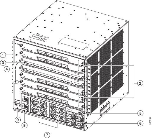
Front Panel
-
Fan tray
-
Five Module slots
-
Two supervisor engine slots
-
Four power supply bays
-
Four power entry modules
-
Two power supply converter modules
-
System On/Off switch
-
System ground connector
|
1 |
Fan tray |
6 |
Power entry modules (PEMs), labeled AC1 through AC4 |
|
2 |
Module slots (line cards) 1, 2, 5,6, and 7 |
7 |
Power supply modules (PSMs), labeled 1 through 4 |
|
3 |
Supervisor engine slot |
8 |
Power supply converter (PSC), labeled PSC1 and PSC2 |
|
4 |
Supervisor engine slot |
9 |
System ground connector |
|
5 |
System On/Off switch |
Chassis
The Cisco Catalyst 6807-XL switch chassis has seven horizontal slots, of which five are module slots and two are supervisor engine slots.
Supervisor Engine
-
Install a 3000 W or higher-capacity power supply.
-
Install supervisor engines only in slot 3 or 4.
In a switch installed with Supervisor Engine 2T if the slots are not occupied by supervisor engines, you can install service modules. However, you cannot install Ethernet modules in slot 3 and 4. Check your software release notes for any restrictions on the type of module that can be installed.
-
In systems with redundant supervisor engines, both the supervisor engines must be of the same model and have the same daughter card configurations.
-
Each supervisor engine must have the resources to run the switch on its own, which means that all the supervisor engine resources are duplicated. Identical supervisor engine memory configurations are recommended, but are not required, as long as the supervisor engine with the smaller memory configuration is sufficient to run the configured features of the switch. Additionally, each supervisor engine must have its own flash device and console port connections.
The uplink ports are fully functional on all redundant supervisor engine models when they are in the standby mode. For more information, see the Catalyst 6500 Series Switch Module Installation Note.
- Supervisor Engine 2T
- Modules supported by Supervisor Engine 2T
- Supervisor Engine 6T
- Modules supported by Supervisor Engine 6T
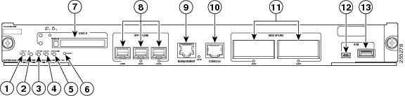
Supervisor Engine 2T
The following are the Supervisor Engine 2T versions supported on the switch.
|
Supervisor Engine 2T Product Numbers |
Description |
|---|---|
|
VS-S2T-10G |
The VS-S2T-10G is shipped with a factory-installed PFC4 daughter card (VS-F6K-PFC4) and a factory-installed MSFC5 daughter card (VS-F6K-MSFC5). There are five uplink ports: two 10GBASE-X Ethernet ports that require the installation ofX2 transceivers and three 1000BASE-X Ethernet ports that require SFP transceivers. |
|
VS-S2T-10G-XL |
The VS-S2T-10G-XL is shipped with a factory-installed PFC4XL daughter card (VS-F6K-PFC4XL) and a factory-installed MSFC5 daughter card (VS-F6K-MSFC5). There are five uplink ports: two 10GBASE-X Ethernet ports that require the installation of X2 transceivers and three 1000BASE-X Ethernet ports that require SFP transceivers. |
|
1 |
STATUS LED |
8 |
1000BASE-X UPLINK ports (requires SFP transceivers) |
|
2 |
ID LED |
9 |
MANAGEMENT port |
|
3 |
SYSTEM LED |
10 |
CONSOLE port |
|
4 |
ACTIVE LED |
11 |
10GBASE-X UPLINK ports (requires X2 transceivers |
|
5 |
PWR MGMT LED |
12 |
USB port |
|
6 |
RESET switch |
13 |
Port currently not supported |
|
7 |
PCMCIA slot |
|
Feature |
Description |
||||
|---|---|---|---|---|---|
|
Chassis compatibility |
Supported on all Catalyst 6500 E-series chassis and Catalyst 6807-XL chassis. |
||||
|
Software requirements (minimum) |
12.2(50)SY |
||||
|
Fan tray requirements |
Both versions of the Supervisor Engine 2T require that a high-speed fan tray be installed in the chassis.
|
||||
|
Slot installation restrictions |
|
||||
|
Hardware restrictions |
Supports only modules equipped with the DFC4-A, DFC4-AXL, DFC4-E, DFC4-EXL, or the CFC daughter cards. Modules equipped with DFC3 daughter cards are not supported. For further information on hardware restrictions and module support, refer to the software release notes at the following URL:http://www.cisco.com/c/en/us/td/docs/switches/lan/catalyst6500/ios/12-2SY/release/notes/ol_20679.html |
||||
|
|
2 GB Compact flash Type 2 (1 GB) |
||||
|
Front panel features |
|||||
|
Status LEDs |
See Supervisor Engine 2T Front Panel Status LEDs for a list of the status LEDs and their descriptions. |
||||
|
RESET switch |
The RESET switch allows you to reset and restart the switch.
|
||||
|
CONSOLE port |
This is a 10/100/1000 port that uses an RJ-45 connector. The CONSOLE port allows you to access the switch either locally (with a console terminal) or remotely (with a modem). The CONSOLE port is an EIA/TIA-232 asynchronous, serial connection with hardware flow control. |
||||
|
Universal Serial Bus (USB) port |
Two USB 2.0 ports are provided. The USB 5-pin mini Type-B connector is used as a console port allowing attachment to PCs that are not equipped with an RS-232 interface. The second USB port is currently not supported. |
||||
|
MANAGEMENT port |
A 10/100/1000 copper port used for out-of-band Ethernet management of the switch. |
||||
|
DISK 0 slot and LED |
One PCMCIA slot is available. The PCMCIA slots allow a Flash PC card to be installed providing additional flash memory. You can use this flash memory to store and run software images or to serve as an I/O device. An eject button is located on the left side, next to each slot. Pushing in on the button ejects the Flash PC card from the slot. The slot supports 1 GB Flash PC cards. The PCMCIA slot has an activity LED associated with it. |
||||
|
Uplink ports (PORT 1 through PORT 5) |
|
||||
|
Uplink port queue structure |
|
||||
|
Pluggable transceivers supported |
For additional information about SFP and X2 transceiver support, see the compatibility matrices listed on this page: http://www.cisco.com/c/en/us/support/interfaces-modules/transceiver-modules/products-device-support-tables-list.html |
||||
|
Hardware-based forwarding engine (Policy Feature Card) |
|
||||
|
Multilayer Switch Feature Card (MSFC) daughter card version installed |
MSFC5 (VS-F6K-MSFC5) |
||||
|
Item |
Specification |
|---|---|
|
Dimensions (H x W x D) |
1.73 x 14.4 x 16.0 in. (4.4 x 36.6 x 40.6 cm). Occupies one slot in the chassis. |
|
Weight |
12.0 lb (5.44 kg) |
|
Power requirement (at 42 VDC) |
|
|
Environment |
|
|
Operating temperature |
|
|
Humidity (RH) ambient (noncondensing) |
10 to 90% |
|
Operating altitude |
|
Modules supported by Supervisor Engine 2T
-
WS-X6704-10GE
-
WS-X6908-10G-2T and WS-X6908-10G-2TXL
-
WS-X6748-GE-TX
-
WS-X6848-TX-2T and WS-X6848-TX-2TXL
-
WS-X6748-SFP
-
WS-X6848-SFP-2T and WS-X6848-SFP-2TXL
-
WS-X6716-10T
-
WS-X6816-10T-2T and WS-X6816-10T-2TXL
-
WS-X6716-10G
-
WS-X6816-10G-2T and WS-X6816-10G-2TXL
-
WS-X6724-SFP
-
WS-X6824-SFP-2T and WS-X6824-SFP-2TXL
-
WS-X6904-40G-2T and WS-X6904-40G-2TXL
-
C6800-8P10G, C6800-8P10G-XL
-
C6800-16P10G, C6800-16P10G-XL
-
C6800-32P10G, C6800-32P10G-XL
-
C6800-48P-SFP, C6800-48P-SFP-XL
-
C6800-48P-TX, C6800-48P-TX-XL
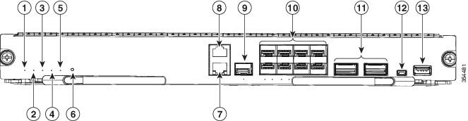
Supervisor Engine 6T
The following are the Supervisor Engine 6T versions supported on the switch.
|
Supervisor Engine 6T Product Numbers |
Description |
|---|---|
|
C6800-SUP6T |
The C6800-SUP6T is shipped with a factory-installed PFC4 daughter card (C6800-PFC). There are eight SFP+ (Multi-Rate) Ethernet ports and two QSFP (40G) Ethernet ports. |
|
C6800-SUP6T-XL |
The C6800-SUP6T-XL is shipped with a factory-installed PFC4XL daughter card (C6800-PFC-XL). There are eight SFP+ (Multi-Rate) Ethernet ports and two QSFP (40G) Ethernet ports. |
|
1 |
STATUS LED |
8 |
Console port |
|
2 |
ID LED |
9 |
Ethernet management SFP port |
|
3 |
SYSTEM LED |
10 |
Eight 10G SFP+ ports |
|
4 |
ACTIVE LED |
11 |
Two 40G QSFP+ uplink ports |
|
5 |
PWR MGMT LED |
12 |
USB mini Type B (console) port |
|
6 |
RESET switch |
13 |
USB Type A host port |
|
7 |
Ethernet management RJ-45 port |
|
Native 10-Gigabit ports |
Configurable 40-Gigabit port |
|---|---|
|
1, 2, 3, 4 |
19 |
|
5, 6, 7, 8 |
20 |
|
Native 40-Gigabit port |
Configurable 10-Gigabit ports |
|---|---|
|
9 |
11, 12, 13, 14 |
|
10 |
15, 16, 17, 18 |
 Note | To configure 40G ports to function as 10G ports, you need to use Cisco QSFP to four SFP+ Active Optical Breakout Cables that connect a 40G QSFP port to four 10G SFP+ ports. |
|
Feature |
Description |
||
|---|---|---|---|
|
Chassis compatibility |
Supported on all Catalyst 6500 E-series chassis and Catalyst 6807-XL chassis. |
||
|
Software requirements (minimum) |
Cisco IOS® Software Release 15.3(1)SY and future releases. |
||
|
Slot installation restrictions |
|
||
|
Hardware restrictions |
Supports only modules equipped with the DFC4-A, DFC4-AXL, DFC4-E, or DFC4-EXL daughter cards. Modules equipped with DFC3 or CFC daughter cards are not supported. For further information on hardware restrictions and module support, refer to the software release notes at the following URL:http://www.cisco.com/c/en/us/td/docs/switches/lan/catalyst6500/ios/15-3SY/release_notes/release_notes.html |
||
|
|
4 GB |
||
|
Front panel features |
|||
|
Status LEDs |
See Supervisor Engine 6T front panel LEDs for a list of the status LEDs and their descriptions. |
||
|
RESET switch |
The RESET switch allows you to reset and restart the switch.
|
||
|
CONSOLE port |
This is a port that uses an RJ-45 connector. The CONSOLE port allows you to access the switch either locally (with a console terminal) or remotely (with a modem). The CONSOLE port is an EIA/TIA-232 asynchronous, serial connection with hardware flow control. |
||
|
Universal Serial Bus (USB) port |
Two USB 2.0 ports are provided. The USB 5-pin mini Type-B connector is used as a console port allowing attachment to PCs that are not equipped with an RS-232 interface. The second USB port is a host port for external USB disk drive. |
||
|
MANAGEMENT port |
A 10/100/1000 copper port used for out-of-band Ethernet management of the switch. It also has a fiber port that can be used as the Ethernet Management port. You can only use one of the ports (copper or fibre) at the same time. |
||
|
Uplink ports |
|
||
|
Uplink port queue structure |
|
||
|
Pluggable transceivers supported |
For information about the transceivers supported, see the compatibility matrices listed on this page: http://www.cisco.com/c/en/us/support/interfaces-modules/transceiver-modules/products-device-support-tables-list.html |
||
|
Hardware-based forwarding engine (Policy Feature Card) |
Built-in |
||
|
Item |
Specification |
|---|---|
|
Dimensions (H x W x D) |
1.73 x 14.1 x 16 in (4.4 x 36 x 40.6 cm) |
|
Weight |
11.64 lbs, 11.73 lbs (XL) |
|
Power requirement (at 42 VDC) |
|
|
Environment |
|
|
Operating temperature |
|
|
Storage temperature |
-40 to 167°F (-40 to 75°C) |
|
Humidity (RH) ambient (noncondensing) |
10 to 90% |
|
Operating altitude |
|
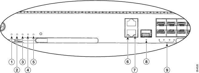
|
1 |
STATUS LED |
6 |
LNK LED |
|
2 |
ID LED |
7 |
ACT LED |
|
3 |
System LED |
8 |
Link LED |
|
4 |
Active LED |
9 |
Port LEDs |
|
5 |
PWR MGMT LED |
|
LED |
Color and Meaning |
|---|---|
|
STATUS |
|
|
ID |
A blue LED that flashes at half-second intervals is used to identify the supervisor engine for servicing purposes. |
|
SYSTEM |
|
|
ACTIVE |
|
|
PWR MGMT |
|
|
LNK/ACT (MANAGEMENT RJ45 port) |
|
|
Link (Management SFP port) |
|
|
SFP+ uplink port LEDs |
If the 10G SFP+ ports are configured to function as 40G ports, ports 1 and 5 represent the Link LED. |
|
QSFP 40G uplink port LEDs) |
If the 40G SFP+ ports are configured to function as 10G ports, ports 11 and 15 represent the Link LED. |
Modules supported by Supervisor Engine 6T
-
C6800-8P10G, C6800-8P10G-XL
-
C6800-16P10G, C6800-16P10G-XL
-
C6800-32P10G, C6800-32P10G-XL
-
C6800-48P-SFP, C6800-48P-SFP-XL
-
C6800-48P-TX, C6800-48P-TX-XL
-
WS-X6904-40G-2T, WS-X6904-40G-2TXL
-
WS-X6908-10G-2T, WS-X6908-10G-2TXL
-
WS-X6824-SFP-2T, WS-X6824-SFP-2TXL
-
WS-X6848-SFP-2T, WS-X6848-SFP-2TXL
-
WS-X6848-TX-2T, WS-X6848-TX-2TXL
-
WS-X6816-10T-2T, WS-X6816-10T-2TXL
Fan Tray
The switch supports a single front-serviceable and hot-swappable fan tray with nine individual fans. The fan tray is responsible for cooling the entire chassis and interfacing with environmental monitors to trigger alarms when conditions exceed thresholds.
-
Model number C6807-XL-FAN.
-
A maximum cooling capacity of 850 CFM1 (120 CFM per slot). At this capacity, the fan tray can cool seven 800 W modules.
-
Four variable-speed operating modes between 3,000 and 6,000 RPM 2 for each fan.
-
Up to three fan failures. The fans that are working increase RPM or CFM.
-
Online Insertion and Removal (OIR) for a minimum of 120 seconds (depending on the ambient temperature).
Note | Individual fans are not field-replaceable units (FRUs). You must replace the fan tray. |
Power Supply Module
The switch supports one to four field-replaceable power supply modules (PSMs) labeled 1 to 4, with a single system On/Off switch.
-
Model number C6800-XL-3KW-AC.
-
Redundant and combined configuration modes. The redundant mode is the default and recommended mode.
-
Only AC input.
-
3000 W when powered with 240VAC, and 1300 W when powered with 120VAC.
-
Only single-phase source AC. Source AC can be out of phase between multiple power supplies or multiple AC-power plugs on the same power supply because all AC power supply inputs are isolated.
|
Redundant Mode (n+1) |
Combined Mode (n+0) |
|
|---|---|---|
|
Description |
The system operates on two to four PSMs. This includes a reserve PSM that is available in case of a failure. The system power supply configuration is n3 PSMs +1 redundant PSM. |
The system operates on one to four power supplies. The power available to the system is the sum of power outputs of all the PSMs in the chassis. |
|
Operating capacity |
|
All available PSMs operate at 100 percent capacity. |
|
In case of failure |
The +1 redundant PSM takes over and operates at 90 percent capacity. |
There is no redundant power supply in this mode. The PSMs that are still operational continue to work. If they are not able to handle the load, the necessary number of modules are shut down. The number of modules that will be shut down depends on the amount of combined power the operational PSMs are able to provide. For example, if you have installed two PSMs, they supply 6000 W, which can power a fully loaded chassis. But if one PSM fails, the power provided drops down to 3000 W, which causes some modules to shut down. |
|
Recommendation |
This is the recommended and default mode. If you have a fully loaded chassis, we recommend that you install at least three PSMs operating in a redundant mode (2+1). |
Although available, we recommend that you do not use this mode. If you are implementing this mode, we recommend at least two PSMs (2+0) operating in the combined mode. |
The PSMs provide 3000 W when powered with 240 VAC, and 1300 W when powered with 120 VAC. In systems where power supply modules provide different wattage, you may not have true redundancy. If the PSM with the higher wattage fails, the PSM with the lower wattage might not be able to handle the entire load by itself and system power management will shut down devices.
Note | When shutting down devices, depending on how much power saving is needed, the system powers down modules in a descending order, starting with the highest-numbered slot. Slots containing supervisor engines are bypassed and are not powered down (Power is automatically reserved for supervisor engine slots). This shutdown order is fixed and cannot be changed. |
You can change the configuration of the power supplies to redundant or combined at any time. If you switch from a redundant to a combined configuration, all the available PSMs are enabled (even a PSM that was disabled because it was of a lower wattage ). If you change from a combined to a redundant configuration, all the available PSMs are initially enabled, and if they are of the same wattage, they remain enabled. If they are of different wattage, a syslog message appears and the lower wattage supply is disabled.
Power Entry Module
The switch supports one to four AC power entry modules (PEMs) labeled AC1 to AC4. The four PEMs connect to the four corresponding PSMs (Labeled 1 to 4), for example, AC1 connects to 1 and so on.
The AC input voltage from the PEM is transmitted to the backplane, which then conducts it to the PSM. The power supply module generates the necessary amount of power.
Power Supply Converter
The switch supports two redundant, field-replaceable 52 V converters labeled PSC1 and PSC2.
The PSC converts the 52 V supplied by the PSM to 3.3 V and conducts it to the backplane. The clock module, VTT modules, and module slots (line cards) require 3.3 V.
LEDs
Use the switch LEDs to monitor switch activity and performance.
For information about module and supervisor engine LEDs, refer to the Catalyst 6500 Ethernet Module Installation Guide and the Catalyst 6500 Series Switch Supervisor Engine Guide available on Cisco.com.
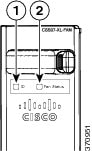
Fan Tray LED
The fan tray includes an ID LED and a Fan Status LED, as shown in the following figure. The different states of the LEDs are described in the following tables.
|
1 |
ID |
2 |
Fan Status |
LED Color |
Meaning |
|---|---|
|
Blue |
Identifies the fan module in the chassis |
LED Color |
Meaning |
|---|---|
|
Green |
Fan is operating normally |
|
Red |
One or more individual fans have failed |
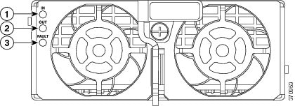
Power Supply Module LEDs
The PSM includes an IN, OUT, and FAULT LED, as shown in the following figure. The different states of the LEDs are described in the following tables.
|
1 |
IN |
3 |
FAULT |
|
2 |
OUT |
|
LED |
LED Color |
Meaning |
|---|---|---|
|
IN |
Green |
Input AC is present and within regulation range |
|
Green (blinking) |
Input AC is present but not within regulation range or AC power was just disconnected and the power supply internal circuitry is still charged |
|
|
OUT 4 |
Green |
Power output is OK |
|
Green (blinking) |
Output is in a power limit or over current condition |
|
|
FAULT |
Red |
Power supply module has malfunctioned |
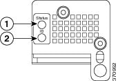
Power Supply Converter LEDs
The PSC includes a Status LED and an ID LED, as shown in the following figure. The different states of the LEDs are described in the following tables.
|
1 |
Status |
2 |
ID |
LED Color |
Meaning |
|---|---|
|
Green |
The A3.3V from the module is within normal range |
|
Red |
The A3.3V from the module is not within normal range |
LED Color |
Meaning |
|---|---|
|
Blue |
Identifies the power supply converter module in the chassis |
Rear Panel
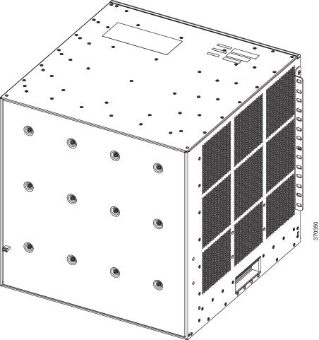
Backplane Bandwidth
Note | The switch supports up to 220G per slot with Supervisor Engine 2T and 440G per slot with Supervisor Engine 6T. The chassis is capable of supporting up to 880G per slot. |
Clock and VTT Module
The switch supports one replaceable clock card with built-in redundancy. The supported model number is CLK-7600.
Three replaceable voltage termination (VTT-E) modules, which are rear-serviceable (located behind back-plate) provide reference voltage for bus signals. The supported model number is WS-C6K-VTT-E.
 Feedback