Cisco Catalyst 6807-XL Switch Hardware Installation Guide
Bias-Free Language
The documentation set for this product strives to use bias-free language. For the purposes of this documentation set, bias-free is defined as language that does not imply discrimination based on age, disability, gender, racial identity, ethnic identity, sexual orientation, socioeconomic status, and intersectionality. Exceptions may be present in the documentation due to language that is hardcoded in the user interfaces of the product software, language used based on RFP documentation, or language that is used by a referenced third-party product. Learn more about how Cisco is using Inclusive Language.
- Updated:
- July 1, 2014
Chapter: Removing and Replacing FRUs
Removing and Replacing FRUs
 Warning | Only trained and qualified personnel should be allowed to install, replace, or service this equipment. Statement 1030 |
- Online Insertion and Removal
- Removing and Installing Power Supplies
- Removing and Installing the Fan Tray
- Removing and Installing the Power Supply Converter
Online Insertion and Removal
The online insertion and removal (OIR) feature allows you to remove and replace modules while the system is online. You can shut down the modules before removal and restart them after insertion, without causing other software or interfaces to shut down.
 Note | Do not remove or install more than one module at a time. After you remove or install a module, check the module LEDs before continuing. |
When a module is removed or installed, the switch stops processing traffic for the module and scans the system for a configuration change. Each interface type is verified against the system configuration, and then the system runs diagnostics on the new module. There is no disruption of normal operation during module insertion or removal.
The switch can bring up only an identical replacement module online. To support the OIR of an identical module, the module configuration is not removed from the running-config file when you remove a module.
If the replacement module is different from the removed module, you must configure it before the switch can bring it online.
Layer 2 MAC addresses are stored in an EEPROM, which allows modules to be replaced online without requiring the system to update switching tables and data structures. Regardless of the types of modules installed, the Layer 2 MAC addresses do not change unless you replace the supervisor engine. If you do replace the supervisor engine, the Layer 2 addresses of all the ports change to those specified in the address allocator on the new supervisor engine.
Removing and Installing Power Supplies
 Caution | Use both hands to install and remove power supplies. |
Installing AC Power Supplies
To install an AC input PSM, follow these steps:
Warning | High leakage current-earth connection essential before connecting to system power supply. Statement 342 |
For ground connection instructions, see
Establishing System Ground You may require a
flat-blade or Number 2 Phillips-head screwdriver to tighten the screw on the
PSM.
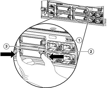
| Step 1 | Remove the blank
cover from the power supply bay if there is one installed. Grasp the two
retaining clips with your thumb and forefinger and squeeze to detatch the blank
cover from the power supply bay.
| ||||||||||
| Step 2 | Remove the PSM from its shipping packaging. | ||||||||||
| Step 3 | Slide the PSM
into the power supply bay. Make sure that the power supply is fully seated in
the bay.
| ||||||||||
| Step 4 | Rotate the latch up and tighten the captive installation screw to lock the latch in place. | ||||||||||
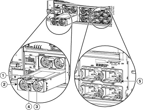
| Step 5 | Plug the AC
power cord (connected to a power source on one end) into the corresponding power entry
module (PEM). For example, if you have installed the PSM in bay 1, plug the
power cord into AC1.
For a list of supported AC power cords for your particular AC input power supply, see 3000 W Power Supply AC Power Cords. | ||||||||||
| Step 6 | Tighten the screw on the cable clamp next to the PEM. This ensures that the power cord is not accidentally pulled out. See callout (5) in Figure 1 |
Removing AC Power Supplies
Each power supply module has a power hold-up time of 20 milliseconds at 100 percent load and fully supports OIR. To remove an AC-input power supply, follow these steps:
Warning | Hazardous voltage or energy is present on the backplane when the system is operating. Use caution when servicing. Statement 1034 |
You may require a flat-blade or Number 2 Phillips-head screwdriver to loosen the captive installation screw.
Removing and Installing the Fan Tray
This section describes how to remove and install the fan tray.
Note | The fan tray is designed to be removed and installed while the system is operating (powered on) without presenting an electrical hazard or damage to the system. |
Installing the Fan Tray
To install the new fan tray, perform these steps:
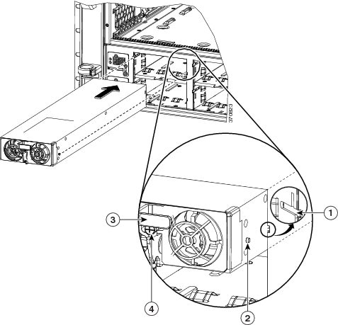
| Step 1 | Remove the fan tray from its packaging. |
| Step 2 | Hold the fan tray handle with one hand. Place your other hand underneath the fan tray. (The correct position involves the fan tray LEDs being on top). |
| Step 3 | Place the fan module into the front of the fan tray bay so that it rests on the chassis, lift the fan module up slightly to align it with the top and bottom of the bay, and then push the fan module into the chassis until it sits in the backplane. The fan module willl snap in. |
What to Do Next
Check that the new fan assembly is installed correctly. For more information, see Checking Fan Tray Installation.
Checking Fan Tray Installation
To verify that the new fan assembly is installed correctly, perform these steps:
| Step 1 | If the switch is powered on, listen for the fans; you should immediately hear them operating. If you do not hear them, ensure that the fan module is inserted completely and correctly in the bay and the outside surface of the fan module is flush with the outside surface of the chassis. |
| Step 2 | Verify that the fan status LED is green. If the LED is red, one or more fans are faulty. |
| Step 3 | If, after several attempts, the fans do not operate, or if you experience trouble with the installation, contact a Cisco customer service representative for assistance. |
Removing the Fan Tray
To remove the fan tray, perform these steps:
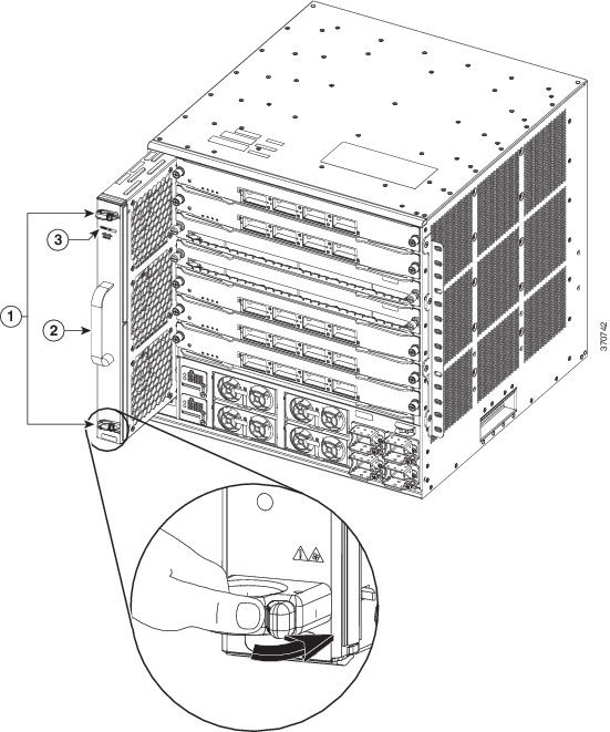
| Step 1 | Locate the fan tray in the chassis. | ||||||||
| Step 2 | Grasp and
simultaneously push both spring latches with your thumb in a left to right
direction. Slide the fan tray half-way out of the bay. Rock it gently, if
necessary, to unseat the power connector from the backplane.
| ||||||||
| Step 3 | Grasp the
handle to pull the fan assembly clear of the chassis, and set it aside.
|
Removing and Installing the Power Supply Converter
This section describes how to remove and install PSCs.
Installing the Power Supply Converter
To install the PSC, perform these steps:
Ensure that the
system (earth) ground connection has been made. For ground connection
instructions, see
Establishing System Ground
You may require a
flat-blade or Number 2 Phillips-head screwdriver to tighten the screw on the
PSC.
| Step 1 | Remove the PSC from its packaging. | ||||
| Step 2 | Slide the PSC into the PSC bay. Ensure that the power supply is fully seated in the bay. | ||||
| Step 3 | Insert the mounting screw and tighten it to fully seat the connectors.
If the system is powered on and PSC is installed properly, the PSC STATUS LED is green. 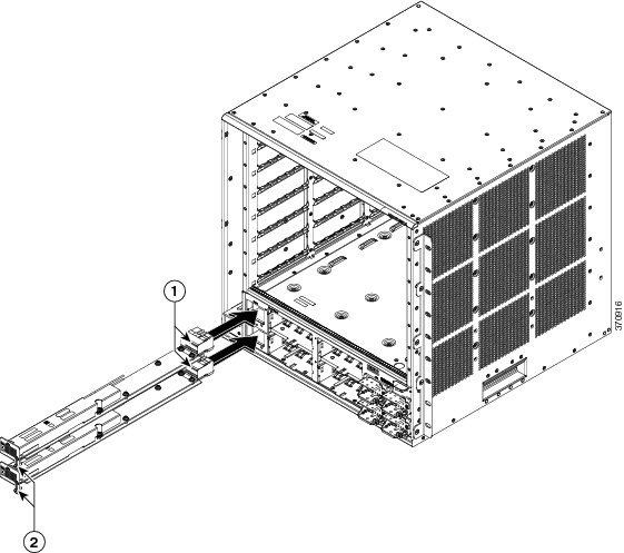
|
Removing the Power Supply Converter
To remove the PSC, perform these steps:
Ensure that the
system (earth) ground connection has been made. For ground connection
instructions, see
Establishing System Ground. You may require a
flat-blade or Number 2 Phillips-head screwdriver to loosen the screw on the
PSC.
 Feedback