Cisco Catalyst 6807-XL Switch Hardware Installation Guide
Bias-Free Language
The documentation set for this product strives to use bias-free language. For the purposes of this documentation set, bias-free is defined as language that does not imply discrimination based on age, disability, gender, racial identity, ethnic identity, sexual orientation, socioeconomic status, and intersectionality. Exceptions may be present in the documentation due to language that is hardcoded in the user interfaces of the product software, language used based on RFP documentation, or language that is used by a referenced third-party product. Learn more about how Cisco is using Inclusive Language.
- Updated:
- July 1, 2014
Chapter: Installing the Switch
- Installation Tasks
- Accessory Kit
- Unpacking the Switch
- L Brackets on the Chassis
- Installing the Rack-Mount Shelf Kit
- Installing Shelf Brackets and Crossbar in a Four-Post Rack with 17.5-inch (44.45 cm) Opening
- Installing Shelf Brackets and Crossbar in a Four-Post Rack with 17.75 inch (45.09 cm) Opening
- Installing Shelf Brackets and Crossbar in a Two-Post Rack with 17.5-inch (44.45 cm) Opening
- Installing Shelf Brackets and Crossbar in a Two-Post Rack with 17.75 inch (45.09 cm) Opening
- Rack-Mounting the Chassis
- Establishing System Ground
- Attaching an ESD Strap
- Verifying the Switch Chassis Installation
- Connecting the Supervisor Engine Console Port
- Installing Transceivers and Module Connectors
Installing the Switch
- Installation Tasks
- Accessory Kit
- Unpacking the Switch
- L Brackets on the Chassis
- Installing the Rack-Mount Shelf Kit
- Rack-Mounting the Chassis
- Establishing System Ground
- Attaching an ESD Strap
- Verifying the Switch Chassis Installation
- Connecting the Supervisor Engine Console Port
- Installing Transceivers and Module Connectors
Installation Tasks
|
Task |
Description |
||
|---|---|---|---|
|
Unpacking the switch |
|
||
|
Installing the rack-mount shelf kit |
Install the rack-mount shelves before you install the chassis in the rack. The shelf brackets help support the weight of the chassis. |
||
|
Rack-mounting the chassis |
Install the chassis in a standard 19-inch rack, either open or enclosed. |
||
|
Connecting the chassis to system ground |
Construct and attach a system ground wire from the building (earth) ground to the system ground point on the chassis. |
||
|
Installing the supervisor engine and line cards and cabling them to the network |
|
||
|
Installing power supplies |
PSMs that you order with the chassis are installed on the chassis when delivered. Blank faceplates are installed on empty power supply module slots. For more information, see the chapter "Removing and Installing Power Supplies". |
||
|
Installing the fan tray |
The fan tray that you order with the chassis is installed on the chassis when delivered. For more information, see the chapter "Removing and Installing the Fan Tray". |
||
|
Powering up the chassis |
After completing the network cabling and making sure that system ground is connected, the power supplies can be turned on. The system powers up and runs through a set of built-in diagnostics. |
 Warning | Class 1 laser product. Statement 1008 |
Warning | This unit is intended for installation in restricted access areas. A restricted access area can be accessed only through the use of a special tool, lock and key, or other means of security. Statement 1017 |
Warning | This unit might have more than one power supply connection. All connections must be removed to de-energize the unit. Statement 1028 |
Warning | Only trained and qualified personnel should be allowed to install, replace, or service this equipment. Statement 1030 |
Warning | To prevent personal injury or damage to the chassis, never attempt to lift or tilt the chassis using the handles on modules (such as power supplies, fans, or cards); these types of handles are not designed to support the weight of the unit. Statement 1032 |
Warning | Hazardous voltage or energy is present on the backplane when the system is operating. Use caution when servicing. Statement 1034 |
Warning | Ultimate disposal of this product should be handled according to all national laws and regulations. Statement 1040 |
Warning | This equipment must be installed and maintained by service personnel as defined by AS/NZS 3260. Incorrectly connecting this equipment to a general-purpose outlet could be hazardous. The telecommunications lines must be disconnected 1) before unplugging the main power connector or 2) while the housing is open, or both. Statement 1043 |
Warning | This product requires short-circuit (overcurrent) protection, to be provided as part of the building installation. Install only in accordance with national and local wiring regulations. Statement 1045 |
Warning | When installing or replacing the unit, the ground connection must always be made first and disconnected last. Statement 1046 |
Warning | Invisible laser radiation may be emitted from disconnected fibers or connectors. Do not stare into beams or view directly with optical instruments. Statement 1051 |
Warning | Installation of the equipment must comply with local and national electrical codes.. Statement 1074 |
Accessory Kit
-
Standard 19-inch rack-mount L brackets—The L brackets are factory installed on the left-front and right-front of the chassis. Associated rack-mounting hardware is included in the kit .
Depending on the manufacturer, the rack posts might be prethreaded to accept either 10-32 or 12-24 screws. If the rack posts are not prethreaded, install 10-32 or 12-24 clip nuts or cage nuts to secure the rack-mount screws. The clip nuts or cage nuts are not included as part of the accessory kit; you must obtain them on your own.
-
Rack-mount shelf kit—This kit is used to support the weight of the chassis while you secure the chassis L brackets to the rack enclosure. It consists of two shelf brackets and a crossbar.
-
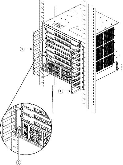
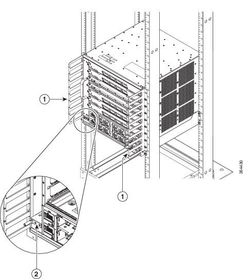
Two 9-slot cable management guides—The cable guides can be installed on the front of the chassis using the same sets of screws that secure the chassis rack-mount brackets to the rack posts.
-
Power supply and module blank panels—The power supply and module blank panels must be installed on any unused power supply bays or module slots to maintain chassis airflow and EMI shielding.
-
Right-angled grounding lug and disposable ESD wrist strap and clip.
-
Screws Table 2 Types of Screws Shipped with the Accessory Kit Type
Quantity
12-24 x 0.75mm
22
10-32 x 0.75mm
22
M4 x 5mm
2
Unpacking the Switch
 Tip | Do not discard the shipping container when you unpack the switch. Flatten the shipping cartons and store them with the pallet. You will require these containers if you have to move or ship the switch in the future. For repacking instructions, see Repacking the Switch. |
-
Check the contents of the accessory kit. Verify that you have received all the listed equipment, including any optional equipment you may have ordered, such as, network interface cables, transceivers, or special connectors.
-
Check the modules in each slot. Ensure that the configuration matches the packing list and that all of the specified interfaces are included.
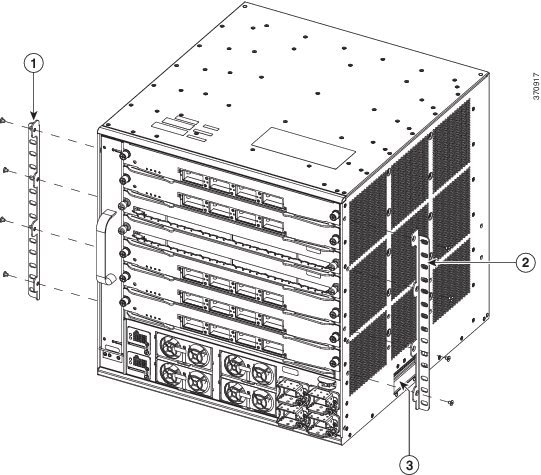
L Brackets on the Chassis
The switch chassis is shipped with two L brackets installed on the front sides of the chassis. The L brackets are secured to the chassis with eight M4 x 5mm flat-head screws (four on each side).
|
1 |
Left L bracket. |
3 |
Handhold |
|
2 |
Right L bracket. |
The L brackets should be installed in this position whether you perform a front rack-mount or a rear rack-mount.
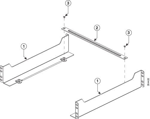
Installing the Rack-Mount Shelf Kit
The rack-mount shelf kit is part of the accessory kit. Install this kit before you install the chassis in the rack. The shelf brackets attach directly to the rack and help support the weight of the chassis while you secure the L brackets to the rack enclosure.
|
Part |
Quantity |
Description |
|---|---|---|
|
Shelf bracket |
2 |
Is attached to the rack posts to form a shelf for the switch chassis to rest on. |
|
Cross Bar |
1 |
Is attached between the two side shelf brackets to secure them together. |
|
12-24 x 0.75-inch Phillips binding head screw |
8 |
Secures the shelf brackets to a rack that requires 12-24 screws (Four for each L bracket). |
|
10-32 x 0.75-inch Phillips binding head screw |
8 |
Secures the shelf brackets to a rack that requires 10-32 screws (Four for each L bracket). |
|
M4 x 5 mm flat-head screw |
2 |
Secures the cross bar with shelf brackets. |
Determine the clearance between the insides of the left and right rails of your rack system and install the shelf brackets accordingly.
- Installing Shelf Brackets and Crossbar in a Four-Post Rack with 17.5-inch (44.45 cm) Opening
- Installing Shelf Brackets and Crossbar in a Four-Post Rack with 17.75 inch (45.09 cm) Opening
- Installing Shelf Brackets and Crossbar in a Two-Post Rack with 17.5-inch (44.45 cm) Opening
- Installing Shelf Brackets and Crossbar in a Two-Post Rack with 17.75 inch (45.09 cm) Opening
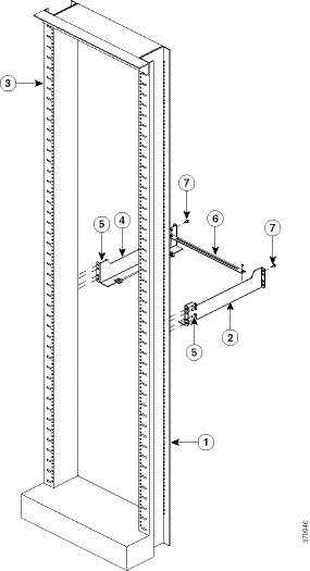
Installing Shelf Brackets and Crossbar in a Four-Post Rack with 17.5-inch (44.45 cm) Opening
You have to rear-mount the shelf brackets and the crossbar in a rack with a 17.5-inch rail-to-rail opening.
Perform these steps:
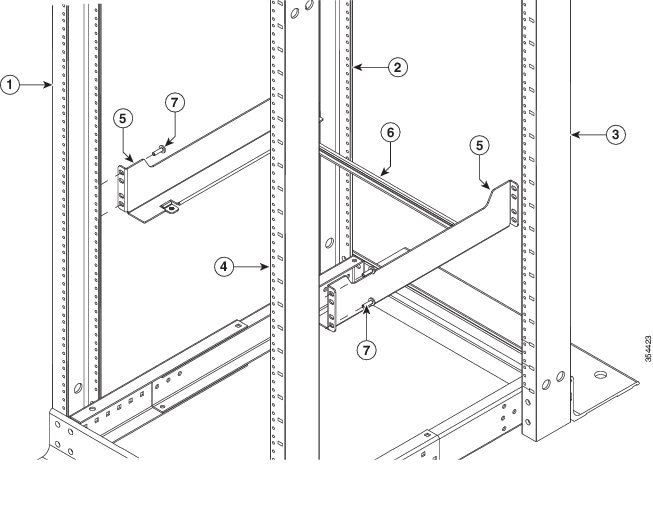
Installing Shelf Brackets and Crossbar in a Four-Post Rack with 17.75 inch (45.09 cm) Opening
You have to front-mount the shelf brackets and crossbar on a rack with a 17.75-inch rail-to-rail opening.
Perform these steps:
| Step 1 | Secure the
crossbar to the shelf brackets by using two M4 screws, with one screw on each
side.
| ||||||||||||||||||
| Step 2 | Position the
rear side of the support flanges of the shelf brackets on the front side of the
fixed front-left and front-right posts of the rack. Align and secure the
bracket to the rack by using the four EA screws (Two EA screws on each side).
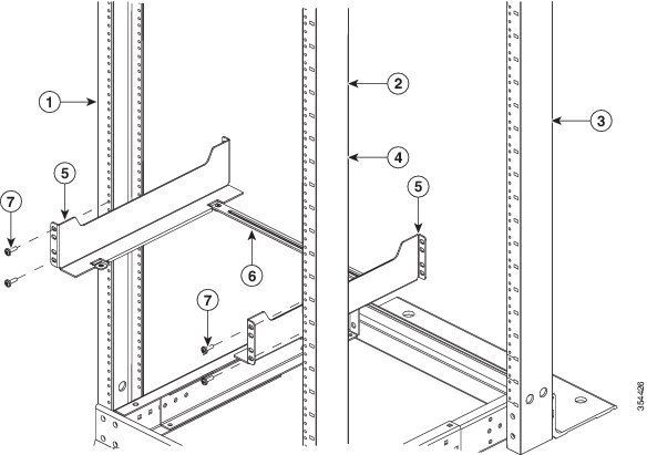
| ||||||||||||||||||
| Step 3 | Adjust the
adjustable rear-left and rear-right rack posts until it touches the shelf
brackets flange surface and secure by using four EA screws, with two EA screws
on each side.
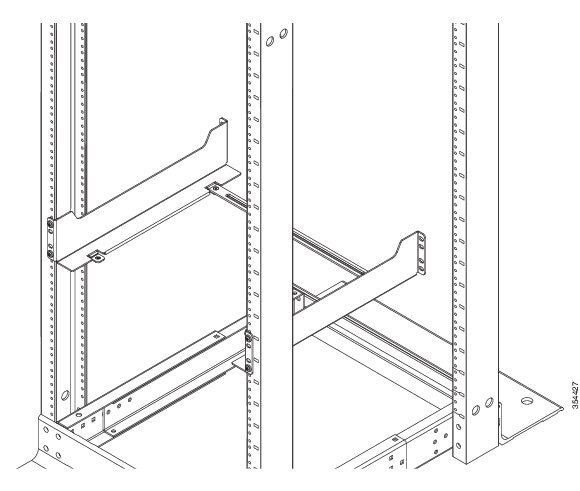  |
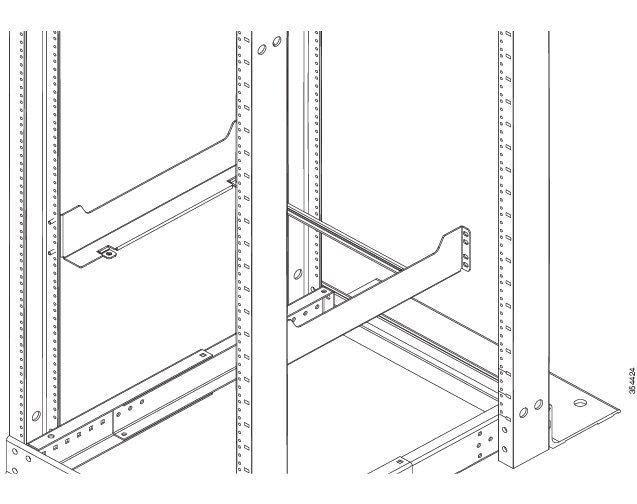
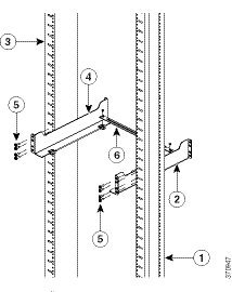
Installing Shelf Brackets and Crossbar in a Two-Post Rack with 17.5-inch (44.45 cm) Opening
You have to rear-mount the shelf brackets and the crossbar for a rack with a 17.5-inch rail-to-rail opening.
Perform these steps:
| Step 1 | Secure the
crossbar to the shelf brackets by using two M4 screws, with one screw on each
side.
| ||||||||||||||
| Step 2 | Position the
front side of the support flanges of the shelf brackets on the rear side of the
left and the right posts of the rack. Align and secure the bracket to the rack
by using the eight EA screws (four EA screws on each side).
|
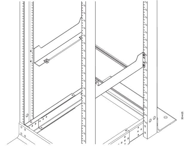
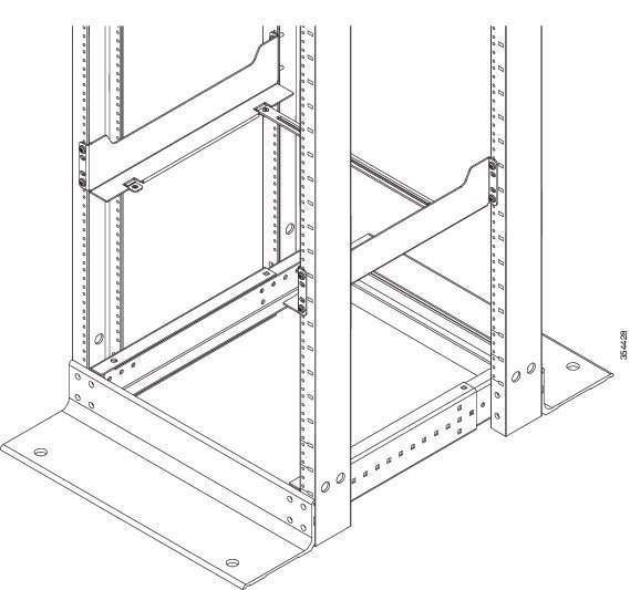
Installing Shelf Brackets and Crossbar in a Two-Post Rack with 17.75 inch (45.09 cm) Opening
You have to front-mount the shelf brackets and crossbar in a rack with a 17.75-inch rail-to-rail opening.
Perform these steps:
| Step 1 | Secure the
crossbar to the shelf brackets by using two M4 screws, with one screw on each
side.
| ||||||||||||
| Step 2 | Position the
rear side of the support flanges of the shelf brackets on the front side of the
left and the right posts of the rack. Align and secure the bracket to the rack
by using the four EA screws (two EA screws on each side).
|
Rack-Mounting the Chassis
Warning | Two people are required to lift the chassis. To prevent injury, keep your back straight and lift with your legs, not your back. Statement 164 |
Tip | We recommend that you have a third person to assist in this procedure. |
To install the switch chassis in the equipment rack, perform these steps:
Read the
Rack-Mounting Guidelines.
Install the
rack-mount shelf kit. See
Installing the Rack-Mount Shelf Kit.
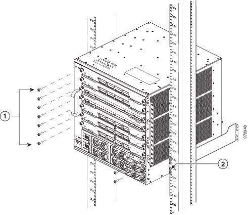
| Step 1 | With a person standing at each side of the chassis, insert one hand into the handhold groove and the other hand near the back of the chassis for balance. Slowly lift the chassis. Avoid sudden twists or moves to prevent injury. | ||||||
| Step 2 | Rest the back end of the chassis on the edges of the rack-mount shelf kit rails and carefully slide the chassis fully into the rack. | ||||||
| Step 3 | Locate the rack
post holes that align with the chassis L bracket holes.
If the rack post holes are prethreaded, determine if the threads are 10-32 or 12-24 and install 14 screws (seven on each side). If the rack post holes are unthreaded, install either 10-32 or 12-24 clip or cage nuts over the rack post holes to accept the installation screws.
| ||||||
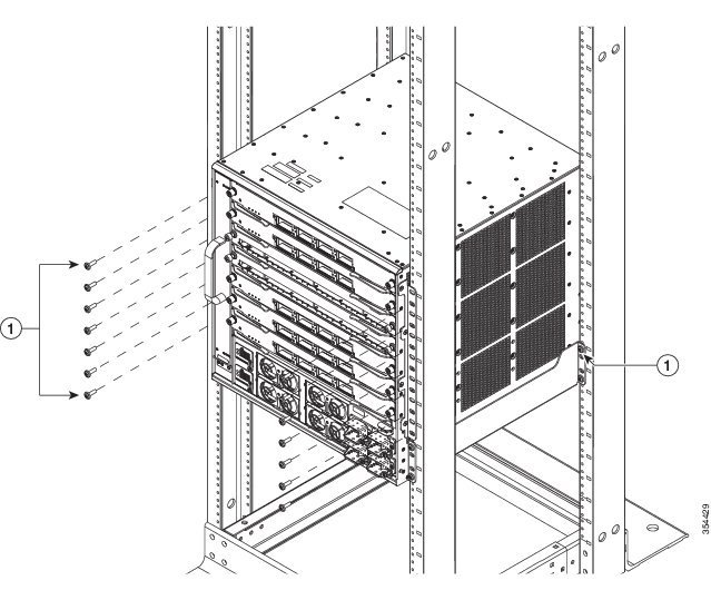
| Step 4 | (Optional)
To install one
or both of the optional cable guide assemblies, position the cable guides such
that the cable guide mounting holes are aligned with the L bracket holes and
the rack rail holes, as shown in the following figure:
|
What to Do Next
After installing the chassis in its location, complete the installation process by:
-
Connecting the chassis to system ground.
-
Installing and connecting the power supplies to the power source.
-
Connecting the network interface cables to the supervisor engine and modules. This may involve installing transceivers before you attach the network interface cables.
-
Powering up the chassis and verifying the installation.
Establishing System Ground
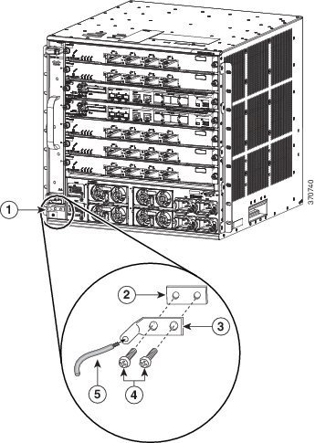
To attach the grounding lug and cable to the grounding pad, perform these steps
To connect the system ground, you require the following tools and materials:
-
Grounding lug—A two-hole right-angled lug. Supports up to 6 AWG wire. Supplied as part of accessory kit.
-
Grounding screws—Two M4 x 8 mm (metric) pan-head screws. Supplied as part of the accessory kit.
-
Grounding wire—Not supplied as part of accessory kit. The grounding wire should be sized according to local and national installation requirements. Depending on the power supply and system, a 12 to 6 AWG copper conductor is required for U.S. installations. Commercially available 6-AWG wire is recommended. The length of the grounding wire depends on the proximity of the switch to proper grounding facilities.
-
No. 1 Phillips screwdriver.
-
Crimping tool to crimp the grounding wire to the grounding lug.
-
Wire-stripping tool to remove the insulation from the grounding wire.
| Step 1 | Use a wire-stripping tool to remove approximately 0.75 inches (19 mm) of the covering from the end of the grounding wire. | ||||||||||||
| Step 2 | Insert the stripped end of the grounding wire into the open end of the right-angled grounding lug. | ||||||||||||
| Step 3 | Crimp the grounding wire in the barrel of the grounding lug. Verify that the ground wire is securely attached to the ground lug. | ||||||||||||
| Step 4 | Secure the
grounding lug to the system ground connector with two M4 screws. Ensure that
the grounding lug and the grounding wire do not interfere with other switch
hardware or rack equipment.
| ||||||||||||
| Step 5 | Prepare the other end of the grounding wire, and connect it to an appropriate grounding point in your site to ensure adequate earth ground for the switch. |
Attaching an ESD Strap
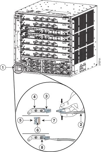
After you install the system ground lug, follow these steps to correctly attach the ESD wrist strap:
| Step 1 | Attach the ESD
wrist strap to bare skin as follows:
| ||||||||||||||||||
| Step 2 | Grasp the spring or alligator clip on the ESD wrist strap and momentarily touch the clip to a bare metal spot (unpainted surface) on the rack. We recommend that you touch the clip to an unpainted rack rail so that any built-up static charge is then safely dissipated to the entire rack. | ||||||||||||||||||
| Step 3 | Attach either
the spring clip or the alligator clip to the ground lug screw as follows:
|
Verifying the Switch Chassis Installation
To verify the switch chassis installation, perform these steps:
| Step 1 | Verify that the ejector levers of each module are fully closed (parallel to the faceplate) to ensure that the supervisor engine and all the switching modules are fully seated in the backplane connectors. | ||
| Step 2 | Check the captive installation screws of each module, power supply, and power supply converter. Tighten loose captive installation screws. | ||
| Step 3 | Verify that all empty module slots have blank faceplates
installed properly. The blank faceplates optimize the air flow through the
chassis and contain EMI.
| ||
| Step 4 | Turn on the power supply switches to power up the system. During the power-up sequence, the system performs a series of bootup diagnostic tests. |
What to Do Next
Tip
When prestaging systems in a nonproduction
environment, we recommend that you run all the diagnostic tests, including the
disruptive tests, to prescreen the systems for failures, if any.
Online Diagnostics
The Cisco Catalyst 6807-XL switches running Cisco IOS have many levels of online diagnostic capabilities. The online diagnostics are divided into the following categories:
-
Bootup—Bootup diagnostics automatically run during bootup, module OIR, or switchover to a backup supervisor engine.
-
Background health—Monitoring diagnostic tests are continuously run by the system to monitor system health.
-
On-demand online diagnostics—On-demand online diagnostics can be used to run any test from the CLI. You can also run on-demand online diagnostics to perform a sanity check on the system hardware. Some of these tests are disruptive and will impact traffic flow. You must follow the on-demand diagnostic guidelines exactly to avoid false failures.
-
Scheduled diagnostics—Scheduled diagnostics can be used to run any of the above tests at user-designated intervals.
Connecting the Supervisor Engine Console Port
-
Configure the switch from the CLI.
-
Monitor network statistics and errors.
-
Configure SNMP agent parameters.
-
Download software updates to the switch, or distribute software images residing in flash memory to attached devices.
 Note | You have to order the necessary cable and adapters to connect a terminal or modem to the console port. |
To connect a terminal to the console port and then connect a modem to the console port using the cable and adapters, follow these steps:
| Step 1 | Connect to the port using the RJ-45-to-RJ-45 cable and the RJ-45-to-DB-25 DTE adapter or the RJ-45-to-DB-9 DTE adapter (labeled Terminal). |
| Step 2 | Check the
corresponding terminal documentation to determine the baud rate.
|
| Step 3 | Connect to the
port using the RJ-45-to-RJ-45 rollover cable and the RJ-45-to-DB-25 DCE adapter
(labeled Modem).
The console port mode switch should be in the IN position (factory default). |
| Step 4 | Position the cable in the cable guide (if installed). Make sure there are no sharp bends in the cable. |
Installing Transceivers and Module Connectors
Some Ethernet modules require that pluggable transceivers be installed in the module port sockets. These transceivers are normally shipped separately from the module and must be installed after the module is installed in the chassis slot.
|
Transceiver or Module Connector Type |
Installation Procedure Document and Link |
|---|---|
|
SFP and SFP+ |
|
|
QSFP+ |
|
|
Cisco OneX Converter |
|
|
X2 |
Cisco 10-Gigabit Ethernet X2 Transceiver Modules Installation Note |
|
Cisco TwinGig and OneX |
Installation Notes for the Cisco TwinGig and OneX Converter Modules |
 Feedback