Virtual Device Context Configuration Guide, Cisco DCNM for LAN, Release 6.x
Bias-Free Language
The documentation set for this product strives to use bias-free language. For the purposes of this documentation set, bias-free is defined as language that does not imply discrimination based on age, disability, gender, racial identity, ethnic identity, sexual orientation, socioeconomic status, and intersectionality. Exceptions may be present in the documentation due to language that is hardcoded in the user interfaces of the product software, language used based on RFP documentation, or language that is used by a referenced third-party product. Learn more about how Cisco is using Inclusive Language.
- Updated:
- June 20, 2012
Chapter: Overview
Overview
This chapter describes virtual device contexts (VDCs) supported on Cisco NX-OS devices.
This chapter includes the following sections:
•![]() Cisco NX-OS Feature Support in VDCs
Cisco NX-OS Feature Support in VDCs
Information About VDCs
The Cisco NX-OS software supports VDCs, which partition a single physical device into multiple logical devices that provide fault isolation, management isolation, address allocation isolation, service differentiation domains, and adaptive resource management. You can manage a VDC instance within a physical device independently. Each VDC appears as a unique device to the connected users. A VDC runs as a separate logical entity within the physical device, maintains its own unique set of running software processes, has its own configuration, and can be managed by a separate administrator.
VDCs also virtualize the control plane, which includes all those software functions that are processed by the CPU on the active supervisor module. The control plane supports the software processes for the services on the physical device, such as the routing information base (RIB) and the routing protocols.
Beginning with Cisco NX-OS release 5.2(1) for the Nexus 7000 Series devices, you can configure Fibre Channel over Ethernet (FCoE). You must configure a dedicated storage VDC to run FCoE on the Cisco Nexus 7000 Series devices. See the Cisco NX-OS FCoE Configuration Guide for Cisco Nexus 7000 and Cisco MDS 9500 for information on FCoE.
When you create a VDC, the Cisco NX-OS software takes several of the control plane processes and replicates them for the VDC. This replication of processes allows VDC administrators to use virtual routing and forwarding (VRF) instance names and VLAN IDs independent of those used in other VDCs. Each VDC administrator interacts with a separate set of processes, VRFs, and VLANs.

Note ![]() The numbers between FCoE and Ethernet VLANs must be unique. That is, the numbers used on the FCoE VLANs in the storage VDCs must be different than any of the VLAN numbers used in the Ethernet VDCs. You can repeat VLAN numbers within separate Ethernet VDCs. The number space for FCoE and Ethernet is shared only for those VDCs configured for port sharing. See Cisco NX-OS FCoE Configuration Guide for Cisco Nexus 7000 and Cisco MDS 9500 for information on configuring FCoE.
The numbers between FCoE and Ethernet VLANs must be unique. That is, the numbers used on the FCoE VLANs in the storage VDCs must be different than any of the VLAN numbers used in the Ethernet VDCs. You can repeat VLAN numbers within separate Ethernet VDCs. The number space for FCoE and Ethernet is shared only for those VDCs configured for port sharing. See Cisco NX-OS FCoE Configuration Guide for Cisco Nexus 7000 and Cisco MDS 9500 for information on configuring FCoE.
Figure 1-1 shows how the Cisco NX-OS software segments the physical device into VDCs. The benefits include VDC-level fault isolation, VDC-level administration, separation of data traffic, and enhanced security.
Figure 1-1 Segmentation of Physical Device

VDC Architecture
The Cisco NX-OS software provides the base upon which VDCs are supported.
This section includes the following topics:
•![]() Kernel and Infrastructure Layer
Kernel and Infrastructure Layer
Kernel and Infrastructure Layer
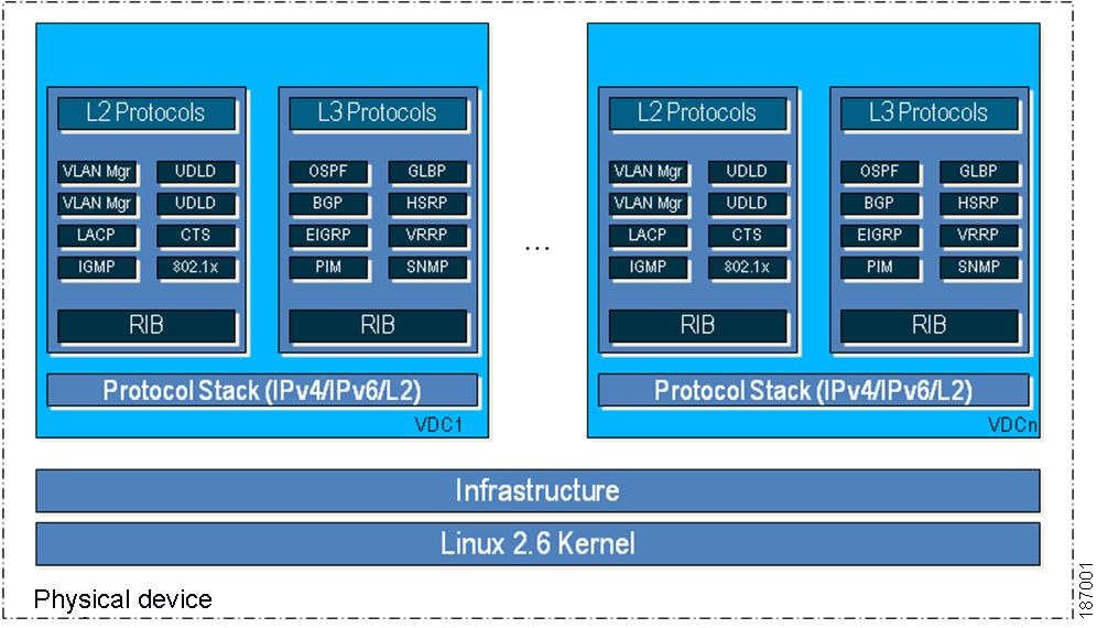
The basis of the Cisco NX-OS software is the kernel and infrastructure layer. A single instance of the kernel supports all of the processes and VDCs that run on the physical device. The infrastructure layer provides an interface between the higher layer processes and the hardware resources of the physical device, such as the ternary content addressable memory (TCAM). Having a single instance of this layer reduces the complexity for the management of the hardware resources and helps scale the Cisco NX-OS software performance by avoiding duplication of the system management process (see Figure 1-2).
The infrastructure also enforces isolation across VDCs. A fault that is generated within a VDC does not impact the services in other VDCs. This feature limits the impact of software faults and greatly improves reliability of the device.
Some nonvirtualized services have only a single instance for all VDCs. These infrastructure services participate in creating VDCs, moving resources across VDCs, and monitoring individual protocol services within a VDC.
The Cisco NX-OS software creates a virtualized control plane for each VDC.The virtualized control plane within the VDCs processes all the protocol-related events.
All the Layer 2 and Layer 3 protocol services run within a VDC. Each protocol service that is started within a VDC runs independently of the protocol services in other VDCs. The infrastructure layer protects the protocol services within a VDC so that a fault or other problem in a service in one VDC does not impact other VDCs. The Cisco NX-OS software creates these virtualized services only when a VDC is created. Each VDC has its own instance of each service. These virtualized services are unaware of other VDCs and only work on resources assigned to that VDC. Only a user with the network-admin role can control the resources available to these virtualized services.
Figure 1-2 VDC Architecture
MAC Addresses
The default VDC has a MAC address. Subsequent nondefault VDCs that you create are assigned MAC addresses automatically as part of the bootup process.
Default VDC
The physical device always has one VDC, the default VDC (VDC 1). When you first log in to a new Cisco NX-OS device, you begin in the default VDC.
You must be in the default VDC to create, change attributes for, or delete a nondefault VDC. The Cisco NX-OS software can support up to four VDCs, including the default VDC, which means that you can create up to three VDCs.
If you have the network-admin role privileges, you can manage the physical device and all VDCs from the default VDC (see the "VDC Default User Roles" section).
Communication Between VDCs
The Cisco NX-OS software does not support direct communication between VDCs on a single physical device. You must make a physical connection from a port that is allocated to one VDC to a port that is allocated to the other VDC to allow the VDCs to communicate. Each VDCs has its own VRFs for communicating with other VDCs (see the "Logical Resources" section).
Storage VDCs
Beginning with Cisco NX-OS Release 5.2(1) for the Nexus 7000 Series devices, you can run FCoE on the F Series modules. You create separate storage VDCs to run FCoE. You can have only one storage VDC on the device, and you cannot configure the default VDC as a storage VDC.
After you create the storage VDC, you assign specified FCoE VLANs. Finally, you configure interfaces on the Nexus 7000 Series device as either dedicated FCoE interfaces or as shared interfaces, which can carry both Ethernet and FCoE traffic. See the Cisco NX-OS FCoE Configuration Guide for Cisco Nexus 7000 and Cisco MDS 9500 for information on configuring FCoE.
Note ![]() You can create storage VDCs only on the F Series module. On the F Series module, you must assign the interfaces on the port group to the same VDC. See the "Physical Resources" section for information on the port groups for the F Series module.
You can create storage VDCs only on the F Series module. On the F Series module, you must assign the interfaces on the port group to the same VDC. See the "Physical Resources" section for information on the port groups for the F Series module.
For more information about creating VDCs with FCoE, see Chapter 3 "Creating VDCs with the VDC Setup Wizard" and the Cisco NX-OS FCoE Configuration Guide for Cisco Nexus 7000 and Cisco MDS 9500 book.
VDC Resources
If you have the network-admin user role, you can allocate physical device resources exclusively for the use of a VDC. Once a resource is assigned to a specific VDC, you can manage it only from that VDC. The Cisco NX-OS software allows you to control how the logical and physical resources are assigned to each VDC. Users logging directly into the VDC can only see this limited view of the device and can manage only those resources that the network administrator explicitly assigns to that VDC. Users within a VDC cannot view or modify resources in other VDCs.
Note ![]() You must have the network-admin role to allocate resources to a VDC (see the "VDC Default User Roles" section).
You must have the network-admin role to allocate resources to a VDC (see the "VDC Default User Roles" section).
This section includes the following topics:
Physical Resources
The only physical resources that you can allocate to a VDC are the Ethernet interfaces. For the Ethernet VDCs, each physical Ethernet interface can belong to only one VDC, including the default VDC, at any given time. When you are working with shared interfaces in the storage VDC, the physical interface can belong to both one Ethernet VDC and one storage VDC simultaneously, but to no more than one of each.
Initially, all physical interfaces belong to the default VDC (VDC 1). When you create a new VDC, the Cisco NX-OS software creates the virtualized services for the VDC without allocating any physical interfaces to it. After you create a new VDC, you can allocate a set of physical interfaces from the default VDC to the new VDC.
When you allocate an interface to a VDC, all configuration for that interface is erased. You, or the VDC administrator, must configure the interface from within the VDC. Only the interfaces allocated to the VDC are visible for configuration.
Note ![]() Beginning with Cisco Release 5.2(1) for Nexus 7000 Series devices, all members of a port group are automatically allocated to the VDC when you allocate an interface.
Beginning with Cisco Release 5.2(1) for Nexus 7000 Series devices, all members of a port group are automatically allocated to the VDC when you allocate an interface.
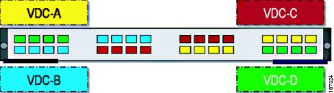
The following Cisco Nexus 7000 Series Ethernet modules have four port groups that consist of 2, 4, 8, or 12 interfaces each, depending on the module: N7K-M148GS-11L, N7K-M148GT-11, N7K-M148GS-11, N7K-M132XP-12, or N7K-M108X2-12L. You must assign all interfaces in the corresponding port group to the same VDC. See the example for module N7K-M132XP-12 in Figure 1-3.
Figure 1-3 Example Interface Allocation for Port Groups on a Cisco 7000 Series 10-Gbps Ethernet Module (N7K-M132XP-12)
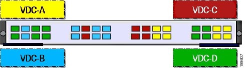
On the Cisco Nexus 7000 Series 32-port, 10-Gbps Ethernet module (N7K-F132XP-15), you must allocate the interfaces on your physical device in the specified combination. This module has 16 port groups that consist of 2 ports each. You must assign the specified port pairs in the same VDC (see Figure 1-4).
For more information on ports that can be paired, see Chapter 3 "Creating VDCs with the VDC Setup Wizard."
Figure 1-4 Example Interface Allocation for Port Groups on a Cisco 7000 Series 10-Gbps Ethernet Module (N7K-F132XP-15)
For more information on port groups on the Cisco Nexus 7000 Series 10-Gbps Ethernet modules, see the Cisco Nexus 7000 Series Hardware Installation and Reference Guide.
Logical Resources
Each VDC acts as a separate logical device within a single physical device, which means that all the namespaces are unique within a VDC. However, you cannot use an identical namespace within a storage VDC and an Ethernet VDC.
When you create a VDC, it has its own default VLAN and VRF that is not shared with other VDCs. You can also create other logical entities within a VDC for the exclusive use of that VDC. These logical entities include SPAN monitoring sessions, port channels, VLANs, and VRFs.
Note ![]() You can have a maximum of two SPAN monitoring sessions on your physical device.
You can have a maximum of two SPAN monitoring sessions on your physical device.
When you create a logical entity in a VDC, only users in that VDC can use it even when it has the same identifier as an another logical entity in another VDC. For example, each VDC can support a maximum of 4096 VLANs. The Cisco NX-OS software supports up to four VDCs and, therefore, 16,384 unique VLANs. A VDC administrator can configure VLAN IDs independently of the VLAN IDs used in other Ethernet VDCs on the same physical device. For example, if VDC administrators for Ethernet VDC A and Ethernet VDC B both create VLAN 100, these VLANs are internally mapped to separate unique identifiers (see Figure 1-5).
Figure 1-5 Example VLAN Configuration for Ethernet VDCs

Note ![]() When you are working with both storage VDCs and Ethernet VDCs, the VLAN ID and logical entity must be entirely separate for the storage VDCs.
When you are working with both storage VDCs and Ethernet VDCs, the VLAN ID and logical entity must be entirely separate for the storage VDCs.
VDC Resource Templates
A network administrator can allocate resources to VDCs using resource templates. Each resource template describes how a set of resources are allocated to a VDC. When you create a VDC, you use a VDC resource template to set limits on the number of certain logical entities that you can create in the VDC. These logical entities include port channels, SPAN monitor sessions, VLANs, IPv4 and IPv6 route memory, and VRFs. You can create a VDC resource template or use the default VDC resource template provided by the Cisco NX-OS software.
For more information on VDC resource templates, see Chapter 2 "Configuring VDC Resource Templates."
Configuration Files
Each VDC maintains a separate configuration file in NVRAM, reflecting the configuration of interfaces allocated to the VDC and any VDC-specific configuration elements such as VDC user accounts and VDC user roles. The separation of the VDC configuration files provides security and fault isolation that protects a VDC from configuration changes on another VDC.
Separate VDC configuration files also provide configuration isolation. The resources in each VDC might have IDs that overlap without affecting the configuration of the other VDCs. For example, the same VRF IDs, port-channel numbers, VLAN IDs, and management IP address can exist on multiple Ethernet VDCs.
VDC Management
Each VDC can be managed by a different VDC administrator. An action taken by a VDC administrator in one VDC does not impact users in other VDCs. A VDC administrator within a VDC can create, modify, and delete the configuration for resources allocated to the VDC with no impact to other VDCs.
This section includes the following topics:
VDC Default User Roles
The Cisco NX-OS software has default user roles that the network administrator can assign to the user accounts that administer VDCs. These user roles make available a set of commands that the user can execute after logging into the device. All commands that the user is not allowed to execute are hidden from the user or return an error.
Note ![]() You must have the network-admin or vdc-admin role to create user accounts in a VDC.
You must have the network-admin or vdc-admin role to create user accounts in a VDC.
The Cisco NX-OS software provides default user roles with different levels of authority for VDC administration as follows:
•![]() network-admin—The network-admin role exists only in the default VDC and allows access to all the global configuration commands (such as reload and install) and all the features on the physical device. A custom user role is not granted access to these network-admin-only commands or to other commands that are scoped admin-only. Only the network administrator can access all the commands related to the physical state of the device. This role can perform system-impacting functions such as upgrading software and running an Ethernet analyzer on traffic. Network administrators can create and delete VDCs, allocate resources for these VDCs, manage device resources reserved for the VDCs, and configure features within any VDC. Network administrators can also access nondefault VDCs using the switchto vdc command from the default VDC. When network administrators switch to a nondefault VDC, they acquire vdc-admin permissions, which are the highest permissions available in a nondefault VDC.
network-admin—The network-admin role exists only in the default VDC and allows access to all the global configuration commands (such as reload and install) and all the features on the physical device. A custom user role is not granted access to these network-admin-only commands or to other commands that are scoped admin-only. Only the network administrator can access all the commands related to the physical state of the device. This role can perform system-impacting functions such as upgrading software and running an Ethernet analyzer on traffic. Network administrators can create and delete VDCs, allocate resources for these VDCs, manage device resources reserved for the VDCs, and configure features within any VDC. Network administrators can also access nondefault VDCs using the switchto vdc command from the default VDC. When network administrators switch to a nondefault VDC, they acquire vdc-admin permissions, which are the highest permissions available in a nondefault VDC.
•![]() network-operator—The network-operator role exists only in the default VDC and allows users to display information for all VDCs on the physical device. This role allows access to all the network-operator-only show commands such as the show running-config vdc and show install all status commands. Users with network-operator roles can access nondefault VDCs using the switchto vdc command from the default VDC.
network-operator—The network-operator role exists only in the default VDC and allows users to display information for all VDCs on the physical device. This role allows access to all the network-operator-only show commands such as the show running-config vdc and show install all status commands. Users with network-operator roles can access nondefault VDCs using the switchto vdc command from the default VDC.
•![]() vdc-admin—Users who have the vdc-admin role can configure all features within a VDC. Users with either the network-admin or vdc-admin role can create, modify, or remove user accounts within the VDC. All configurations for the interfaces allocated to a VDC must be performed within the VDC. Users with the vdc-admin role are not allowed to execute any configuration commands related to the physical device.
vdc-admin—Users who have the vdc-admin role can configure all features within a VDC. Users with either the network-admin or vdc-admin role can create, modify, or remove user accounts within the VDC. All configurations for the interfaces allocated to a VDC must be performed within the VDC. Users with the vdc-admin role are not allowed to execute any configuration commands related to the physical device.
•![]() vdc-operator—Users assigned with the vdc-operator role can display information only for the VDC. Users with either the network-admin or vdc-admin role can assign the vdc-operator role to user accounts within the VDC. The vdc-operator role does not allow the user to change the configuration of the VDC.
vdc-operator—Users assigned with the vdc-operator role can display information only for the VDC. Users with either the network-admin or vdc-admin role can assign the vdc-operator role to user accounts within the VDC. The vdc-operator role does not allow the user to change the configuration of the VDC.
If you do not need more than three VDCs, we recommend that you leave the default VDC as an admin VDC and use the other VDCs as active data-plane virtual switches. Make sure to restrict default VDC access to a select few administrators who are allowed to modify the global configuration (network-admin role). Remember that you can configure some features (such as CoPP, rate limits, and IP tunnels) only in the default VDC. You cannot configure the default VDC as a storage VDC.
If the default VDC must be used for data-plane traffic, administrators who require default VDC configuration access but not global configuration access should be assigned with the vdc-admin role. This role restricts administrative functions to the default VDC exclusively and prevents access to global VDC configuration commands. For more information on user accounts and roles, see the Security Configuration Guide, Cisco DCNM for LAN, Release 5.x.
Configuration Modes
The Cisco NX-OS software has two main configuration modes for VDCs, VDC configuration mode in the default VDC and global configuration mode within the VDC itself.
In the VDC configuration mode in the default VDC, you can allocate interfaces to the VDCs and change VDC attributes. You can enter VDC configuration mode from global configuration mode on the default VDC. Only users with the network-admin role can access VDC configuration mode. The following example shows how to enter VDC configuration mode:
switch# configure terminal
switch(config)# vdc Enterprise
switch(config-vdc)#
In the global configuration mode in a VDC, you can configure Cisco NX-OS features for nondefault VDCs. You can access this configuration mode by logging in to the VDC and entering global configuration mode.You must have a user role that allows read and write access to the VDC to use this configuration mode. The following example shows how to enter global configuration mode for a VDC:
switch-Enterprise# configure terminal
switch-Enterprise(config)#
VDC Management Connections
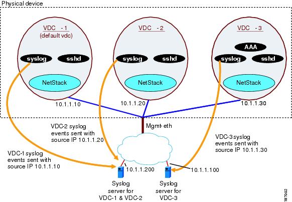
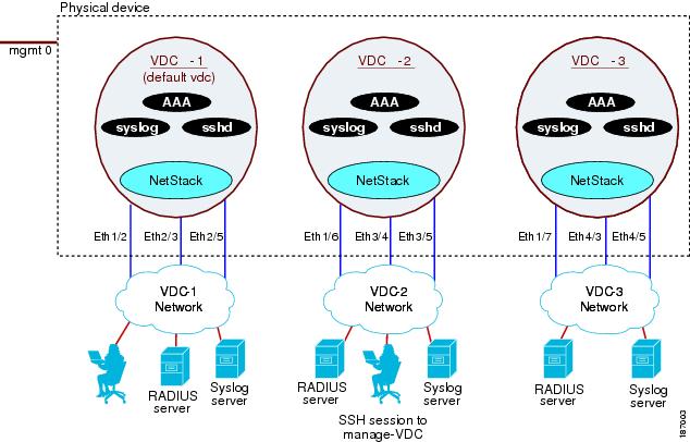
The Cisco NX-OS software provides a virtual management (mgmt 0) interface for out-of-band management for each VDC. You can configure this interface with a separate IP address that is accessed through the physical mgmt 0 interface (see Figure 1-6). Using the virtual management interface allows you to use only one management network, which can share the AAA servers and syslog servers among the VDCs.
Figure 1-6 Out-of-Band VDC Management Example
VDCs also support in-band management. You can access the VDC using one of the Ethernet interface allocated to the VDC (see Figure 1-7). Using the in-band management allows you to use only separate management networks, which ensures the separation of the AAA servers and syslog servers among the VDCs.
Figure 1-7 In-Band VDC Management Example
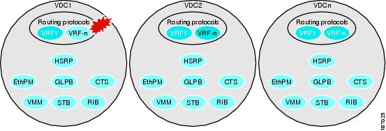
VDC Fault Isolation
The VDC architecture can prevent failures within one VDC from impacting other VDCs on the same physical device. For instance, an Open Shortest Path First (OSPF) process that fails in one VDC does not affect the OSPF processes in other VDCs in the same physical device.
Figure 1-8 shows that a fault in a process running in VDC 1 does not impact any of the running processes in the other VDCs.
Figure 1-8 Fault Isolation within VDCs
The Cisco NX-OS software also provides debugging and syslog message logging at the VDC level. VDC administrators can use these tools to troubleshoot problems with the VDC. For more information on VDC troubleshooting, see the Cisco Nexus 7000 Series NX-OS Troubleshooting Guide.
The Cisco NX-OS software incorporates high availability (HA) features that minimize the impact on the data plane if the control plane fails or a switchover occurs. The different HA service levels provide data plane protection, including service restarts, stateful supervisor module switchovers, and in-service software upgrades (ISSUs). All of these high availability features support VDCs. For more information on HA in the Cisco NX-OS software, see the Cisco Nexus 7000 Series NX-OS High Availability and Redundancy Guide, Release 5.x.
Cisco NX-OS Feature Support in VDCs
VDC support for the Cisco NX-OS software features varies, depending on the feature. For most of the Cisco NX-OS software features, configuration and operation are local to the current VDC. However, the exceptions are as follows:
•![]() Control plane policing (CoPP)—Because of the hardware support, you can configure CoPP policies only in the default VDC. The CoPP policies apply across all VDCs on the physical device.
Control plane policing (CoPP)—Because of the hardware support, you can configure CoPP policies only in the default VDC. The CoPP policies apply across all VDCs on the physical device.
•![]() Rate limits—Because of the hardware support, you can configure rate limits only in the default VDC. The rate limits apply across all VDCs on the physical device.
Rate limits—Because of the hardware support, you can configure rate limits only in the default VDC. The rate limits apply across all VDCs on the physical device.
•![]() IP tunnels—You can create VDC tunnels only in the default VDC.
IP tunnels—You can create VDC tunnels only in the default VDC.
•![]() FCoE—Beginning with the Cisco NX-OS Release 5.2(1) for the Nexus 7000 Series devices, VDCs have FCoE support to provide users with local area network (LAN)/storage area network (SAN) management separation on one physical Ethernet interface. The Cisco NX-OS supports both Ethernet and FCoE only in nondefault VDCs that control the Ethernet and storage portions of the network. You can have only one storage VDC configured on the device. For more information about creating VDCs with FCoE, see Chapter 3 "Creating VDCs with the VDC Setup Wizard" and the Cisco NX-OS FCoE Configuration Guide.
FCoE—Beginning with the Cisco NX-OS Release 5.2(1) for the Nexus 7000 Series devices, VDCs have FCoE support to provide users with local area network (LAN)/storage area network (SAN) management separation on one physical Ethernet interface. The Cisco NX-OS supports both Ethernet and FCoE only in nondefault VDCs that control the Ethernet and storage portions of the network. You can have only one storage VDC configured on the device. For more information about creating VDCs with FCoE, see Chapter 3 "Creating VDCs with the VDC Setup Wizard" and the Cisco NX-OS FCoE Configuration Guide.
For information on VDC support for a specific feature, see the configuration information for that feature.
 Feedback