- New and Changed Information
- Preface
- Overview
- Configuring CFS
- Configuring NTP
- Configuring PTP
- Configuring CDP
- Configuring System Message Logging
- Configuring Smart Call Home
- Configuring Rollback
- Configuring Session Manager
- Configuring the Scheduler
- Configuring SNMP
- Configuring RMON
- Configuring Online Diagnostics
- Configuring the Embedded Event Manager
- Configuring Onboard Failure Logging
- Configuring SPAN
- Configuring ERSPAN
- Configuring LLDP
- Configuring NetFlow
- Supported RFCs
- EEM Events and Examples
- Configuration Limits for Cisco NX-OS System Management
Cisco Nexus 7000 Series NX-OS System Management Configuration Guide, Release 5.x
Bias-Free Language
The documentation set for this product strives to use bias-free language. For the purposes of this documentation set, bias-free is defined as language that does not imply discrimination based on age, disability, gender, racial identity, ethnic identity, sexual orientation, socioeconomic status, and intersectionality. Exceptions may be present in the documentation due to language that is hardcoded in the user interfaces of the product software, language used based on RFP documentation, or language that is used by a referenced third-party product. Learn more about how Cisco is using Inclusive Language.
- Updated:
- May 25, 2010
Chapter: Configuring SPAN
Configuring SPAN
This chapter describes how to configure an Ethernet switched port analyzer (SPAN) to analyze traffic between ports on Cisco NX-OS devices.
Information About SPAN
SPAN analyzes all traffic between source ports by directing the SPAN session traffic to a destination port with an external analyzer attached to it.
You can define the sources and destinations to monitor in a SPAN session on the local device.
This section includes the following topics:
- SPAN Sources
- SPAN Destinations
- SPAN Sessions
- Virtual SPAN Sessions
- Multiple SPAN Sessions
- High Availability
- Virtualization Support
SPAN Sources
The interfaces from which traffic can be monitored are called SPAN sources. Sources designate the traffic to monitor and whether to copy ingress, egress, or both directions of traffic. SPAN sources include the following:
- Ethernet ports
- Port channels
- The inband interface to the control plane CPU—You can monitor the inband interface only from the default VDC. Inband traffic from all VDCs is monitored.
- VLANs—When a VLAN is specified as a SPAN source, all supported interfaces in the VLAN are SPAN sources.
- Remote SPAN (RSPAN) VLANs
- Fabric port channels connected to the Cisco Nexus 2000 Series Fabric Extender
-
Satellite ports and host interface port channels on the Cisco Nexus 2000 Series Fabric Extender—
These interfaces are supported in Layer 2 access mode, Layer 2 trunk mode, and Layer 3 mode.

Note Layer 3 subinterfaces are not supported.
Note A single SPAN session can include mixed sources in any combination of the above.
Characteristics of Source Ports
SPAN source ports have the following characteristics:
- A port configured as a source port cannot also be configured as a destination port.
- An RSPAN VLAN can only be used as a SPAN source.
- If you use the supervisor inband interface as a SPAN source, the following packets are monitored:
– All packets that arrive on the supervisor hardware (ingress)
SPAN Destinations
SPAN destinations refer to the interfaces that monitor source ports. Destination ports receive the copied traffic from SPAN sources.
Characteristics of Destination Ports
SPAN destination ports have the following characteristics:
- Destinations for a SPAN session include Ethernet ports or port-channel interfaces in either access or trunk mode.
- A port configured as a destination port cannot also be configured as a source port.
- A destination port can be configured in only one SPAN session at a time.
- Destination ports do not participate in any spanning tree instance. SPAN output includes Bridge Protocol Data Unit (BPDU) Spanning-Tree Protocol hello packets.
- An RSPAN VLAN cannot be used as a SPAN destination.
- You can configure SPAN destinations to inject packets to disrupt a certain TCP packet stream in support of the Intrusion Detection System (IDS).
- You can configure SPAN destinations to enable a forwarding engine to learn the MAC address of the IDS.
- F1 Series module FabricPath core ports, Fabric Extender HIF ports, HIF port channels, and Fabric PO ports are not supported as SPAN destination ports.
- Shared interfaces cannot be used as SPAN destinations.
- VLAN ACL redirects to SPAN destination ports are not supported.
- All SPAN destinations configured for a given session will receive all spanned traffic. For more information, see the “Virtual SPAN Sessions” section below.
SPAN Sessions
You can create up to 48 SPAN sessions designating sources and destinations to monitor.
Note Only two SPAN sessions, two ERSPAN sessions, or one SPAN session and one ERSPAN session can be running simultaneously.
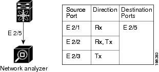
Figure 18-1 shows a SPAN configuration. Packets on three Ethernet ports are copied to destination port Ethernet 2/5. Only traffic in the direction specified is copied.
Figure 18-1 SPAN Configuration
Virtual SPAN Sessions
You can create a virtual SPAN session to monitor multiple VLAN sources and choose only VLANs of interest to transmit on multiple destination ports. For example, you can configure SPAN on a trunk port and monitor traffic from different VLANs on different destination ports.
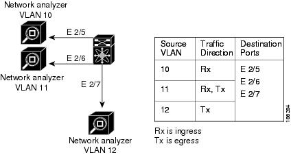
Figure 18-2 shows a virtual SPAN configuration. The virtual SPAN session copies traffic from the three VLANs to the three specified destination ports. You can choose which VLANs to allow on each destination port to limit the traffic that the device transmits on it. In Figure 18-2, the device transmits packets from one VLAN at each destination port.
Note Virtual SPAN sessions cause all source packets to be copied to all destinations, whether the packets are required at the destination or not. VLAN traffic filtering occurs at the egress destination port level.
Figure 18-2 Virtual SPAN Configuration
For information about configuring a virtual SPAN session, see the “Configuring a Virtual SPAN Session” section.
Multiple SPAN Sessions
Although you can define up to 48 SPAN sessions, only two SPAN or ERSPAN sessions can be running simultaneously. You can shut down an unused SPAN session.
For information about shutting down SPAN sessions, see the “Shutting Down or Resuming a SPAN Session” section.
High Availability
The SPAN feature supports stateless and stateful restarts. After a reboot or supervisor switchover, the running configuration is applied. For more information on high availability, see the Cisco Nexus 7000 Series NX-OS High Availability and Redundancy Guide, Release 5.x .
Virtualization Support
A virtual device context (VDC) is a logical representation of a set of system resources. SPAN applies only to the VDC where the commands are entered.
Note You can monitor the inband interface only from the default VDC. Inband traffic from all VDCs is monitored.
For information about configuring VDCs, see the Cisco Nexus 7000 Series NX-OS Virtual Device Context Configuration Guide, Release 5.x .
Licensing Requirements for SPAN
The following table shows the licensing requirements for this feature:
Guidelines and Limitations
SPAN has the following configuration guidelines and limitations:
- For SPAN session limits, see the Cisco Nexus 7000 Series NX-OS Verified Scalability Guide .
- SPAN is not supported for management ports.
- All SPAN replication is performed in the hardware. The supervisor CPU is not involved.
- A destination port can only be configured in one SPAN session at a time.
- You cannot configure a port as both a source and destination port.
- A single SPAN session can include mixed sources in any combination of the following:
– Ethernet ports, but not subinterfaces.
– VLANs, which can be assigned to port channel subinterfaces
– The inband interface to the control plane CPU
- Destination ports do not participate in any spanning tree instance. SPAN output includes Bridge Protocol Data Unit (BPDU) Spanning-Tree Protocol hello packets.
- When a SPAN session contains source ports that are monitored in the transmit or transmit and receive direction, packets that these ports receive may be replicated to the SPAN destination port even though the packets are not actually transmitted on the source ports. Some examples of this behavior on source ports include:
– Traffic that results from flooding
– Broadcast and multicast traffic
- For VLAN SPAN sessions with both ingress and egress configured, two packets (one from ingress and one from egress) are forwarded from the destination port if the packets get switched on the same VLAN.
- VLAN SPAN monitors only the traffic that leaves or enters Layer 2 ports in the VLAN.
- You can monitor the inband interface only from the default VDC. Inband traffic from all VDCs is monitored.
- You can configure an RSPAN VLAN for use only as a SPAN session source.
- You can configure a SPAN session on the local device only.
- Multiple SPAN destinations are not supported when an F1 Series module is present in a VDC. If multiple SPAN destinations are configured in a SPAN session, the session is disabled until the F1 Series module is powered down or moved to another VDC or the multiple SPAN destinations are reduced to a single destination.
- A maximum of two bidirectional sessions are supported when an F1 Series module is present in a VDC.
- A FabricPath core port is not supported as a SPAN destination when an F1 Series module is present in a VDC. However, a FabricPath core port can be configured as a SPAN source interface.
- F1 Series modules are Layer 2 domain line cards. Packets from Layer 3 sources can be spanned and directed to an F1 Series module SPAN destination. An F1 Series module interface cannot be configured as Layer 3, but it can receive Layer 3 traffic in a SPAN destination mode.
- When using SPAN sessions on F1 Series modules, ensure that the total amount of source traffic in a given session is less than or equal to the capacity of the SPAN destination interface or port channel for that session. If the SPAN source traffic exceeds the capacity of the SPAN destination, packet drops might occur on the SPAN source interfaces.
- If you span a core interface when inter-VLAN routing is enabled across L2MP, it is not possible to capture the traffic egressing out of the core interface.
- Beginning with Cisco NX-OS Release 5.2, the Cisco Nexus 2000 Series Fabric Extender interfaces and the fabric port channels connected to the Cisco Nexus 2000 Series Fabric Extender can be configured as SPAN sources. However, they cannot be configured as SPAN destinations.
Note SPAN on Fabric Extender interfaces and fabric port channels is supported on the 32-port, 10-Gigabit M1 and M1 XL modules (N7K-M132XP-12 and N7K-M132XP-12L). SPAN runs on the Cisco Nexus 7000 Series device, not on the Fabric Extender.
- SPAN is supported on Fabric Extender interfaces in Layer 2 access mode, Layer 2 trunk mode, and Layer 3 mode. Layer 3 subinterfaces are not supported.
- If a port channel is the SPAN destination interface for SPAN traffic that is sourced from a Cisco Nexus 7000 M1 Series module, only a single member interface will receive copied source packets. The same limitation does not apply to SPAN traffic sourced from other Cisco Nexux modules, including the Cisco Nexus 7000 M1-XL Series modules.
- Cisco NX-OS does not span Link Layer Discovery Protocol (LLDP) or Link Aggregation Control Protocol (LACP) packets when the source interface is a Fabric Extender HIF (downlink) port or HIF port channel.
- SPAN sessions cannot capture packets with broadcast or multicast MAC addresses that reach the supervisor, such as ARP requests and Open Shortest Path First (OSPF) protocol hello packets, if the source of the session is the supervisor ethernet in-band interface. To capture these packets, you must use the physical interface as the source in the SPAN sessions.
- The rate limit percentage of a SPAN session is based on 10G for all modules (that is, 1% corresponds to 0.1G), and the value is applied per every forwarding engine instance.
- MTU truncation and the SPAN rate limit are supported only on F1 Series modules.
Note MTU truncation and the SPAN rate limit cannot be enabled for the same SPAN session. If you configure both for one session, only the rate limit is allowed on F1 Series modules, and MTU truncation is disabled until you disable the rate limit configuration.
- MTU truncation on egress spanned FabricPath (core) packets is 16 bytes less than the configured value because the SPAN destination removes the core header. In addition, when trunk ports are used as the SPAN destination, the spanned ingress packets have 4 more bytes than the configured MTU truncation size.
- For certain rate limit and packet size values, the SPAN packet rate is less than the configured value because of the internal accounting of packet sizes and internal headers.
- Multicast best effort mode applies only to M1 Series modules.
- SPAN does not capture pause frames in a Fibre Channel over Ethernet (FCoE) network because pause frames sent from the virtual expansion (VE) port are generated and terminated by the outermost MAC layer. For more information on FCoE, see the Cisco NX-OS FCoE Configuration Guide for Cisco Nexus 7000 and Cisco MDS 9500 .
Default Settings
Table 18-1 lists the default settings for SPAN parameters.
Configuring SPAN
This section includes the following topics:
- Configuring a SPAN Session
- Configuring a Virtual SPAN Session
- Configuring an RSPAN VLAN
- Shutting Down or Resuming a SPAN Session
- Configuring MTU Truncation for Each SPAN Session
- Configuring a Source Rate Limit for Each SPAN Session
- Configuring the Multicast Best Effort Mode for a SPAN Session
Note Cisco NX-OS commands for this feature may differ from those in Cisco IOS.
Configuring a SPAN Session
You can configure a SPAN session on the local device only. By default, SPAN sessions are created in the shut state.
For sources, you can specify Ethernet ports, port channels, the supervisor inband interface, VLANs, and RSPAN VLANs. You can specify private VLANs (primary, isolated, and community) in SPAN sources.
A single SPAN session can include mixed sources in any combination of Ethernet ports, VLANs, or the inband interface to the control plane CPU. You cannot specify Ethernet port subinterfaces as sources for a SPAN session.
Note To use a Layer 3 port-channel sub-interface or a normal Layer 3 sub-interface as a SPAN source in the monitor session, configure the VLAN filter on the parent Layer 3 Port channel or Layer 3 interface with the same VLAN as the IEEE 802.1q VLAN encapsulation that is configured on the sub-interface. The VLAN filter configured on the parent interface as source will ensure that the monitored traffic on the SPAN destination port will be only for the VLANs that are configured.
When you specify the supervisor inband interface for a SPAN source, the device monitors all packets that arrive on the supervisor hardware (ingress) and all packets generated by the supervisor hardware (egress).
For destination ports, you can specify Ethernet ports or port-channels in either access or trunk mode. You must enable monitor mode on all destination ports.
BEFORE YOU BEGIN
Make sure that you are in the correct VDC. To switch VDCs, use the switchto vdc command.
You must have already configured the destination ports in access or trunk mode. For more information, see the Cisco Nexus 7000 Series NX-OS Interfaces Configuration Guide, Release 5.x .
SUMMARY STEPS
2. interface ethernet slot / port [ -port ]
4. switchport mode [access | trunk | private-vlan]
5. switchport monitor [ingress [learning]]
6. (Optional) Repeat Steps 2 and 3 to configure monitoring on additional SPAN destinations.
7. no monitor session session-number
8. monitor session session-number
10. source { interface type | vlan { number | range } [ rx | tx | both ]
11. (Optional) Repeat Step 8 to configure all SPAN sources.
12. (Optional) filter vlan { number | range }
13. (Optional) Repeat Step 10 to configure all source VLANs to filter.
14. destination interface type { number | range }
15. (Optional) Repeat Step 12 to configure all SPAN destination ports.
17. (Optional) show monitor session { all | session-number | range session-range } [ brief ]
DETAILED STEPS
Configuring a Virtual SPAN Session
You can configure a virtual SPAN session to copy packets from source ports, VLANs, and RSPAN VLANs to destination ports on the local device. By default, SPAN sessions are created in the shut state.
For sources, you can specify ports, VLANs, or RSPAN VLANs.
For destination ports, you can specify Ethernet ports. You can choose which VLANs to allow on each destination port to limit the traffic that the device transmits on it.
BEFORE YOU BEGIN
Ensure that you are in the correct VDC (or use the switchto vdc command).
You have already configured the destination ports in trunk mode. For more information, see the Cisco Nexus 7000 Series NX-OS Interfaces Configuration Guide, Release 5.x .
You have already configured the destination ports to monitor a SPAN session with the switchport monitor command.
SUMMARY STEPS
2. no monitor session session-number
3. monitor session session-number
4. source { interface type | vlan } { number | range } [ rx | tx | both ]
5. (Optional) Repeat Step 4 to configure all virtual SPAN VLAN sources.
6. destination interface type { number | range }
7. (Optional) Repeat Step 6 to configure all virtual SPAN destination ports.
9. (Optional) show monitor session { all | session-number | range session-range } [ brief ]
10. interface ethernet slot / port [- port ]
11. switchport trunk allowed vlan {{ number | range } | add { number | range } | except { number | range } | remove { number | range } | all | none }
12. (Optional) Repeat Steps 10 and 11 to configure the allowed VLANs on each destination port.
13. (Optional) show interface ethernet slot / port [- port ] trunk
DETAILED STEPS
DETAILED STEPS
Shutting Down or Resuming a SPAN Session
You can shut down SPAN sessions to discontinue the copying of packets from sources to destinations. Because only two SPAN sessions can be running simultaneously, you can shut down one session in order to free hardware resources to enable another session. By default, SPAN sessions are created in the shut state.
You can resume (enable) SPAN sessions to resume the copying of packets from sources to destinations. In order to enable a SPAN session that is already enabled but operationally down, you must first shut it down and then enable it.
You can configure the shut and enabled SPAN session states with either a global or monitor configuration mode command.
SUMMARY STEPS
2. monitor session { session-range | all } shut
3. no monitor session { session-range | all } shut
DETAILED STEPS
Configuring MTU Truncation for Each SPAN Session
To reduce the SPAN traffic bandwidth, you can configure the maximum bytes allowed for each replicated packet in a SPAN session. This value is called the maximum transmission unit (MTU) truncation size. Any SPAN packet larger than the configured size is truncated to the configured size.
Note MTU truncation and the SPAN rate limit cannot be enabled for the same SPAN session. If you configure both for one session, only the rate limit is allowed on F1 Series modules, and MTU truncation is disabled until you disable the rate limit configuration.
DETAILED STEPS
Configuring a Source Rate Limit for Each SPAN Session
When a SPAN session is configured with multiple interfaces or VLANs as the sources in a high-traffic environment, the destination port can be overloaded, causing the normal data traffic to be disrupted at the source port. You can alleviate this problem as well as traffic overload on the source forwarding instance by configuring a source rate limit for each SPAN session.
Note MTU truncation and the SPAN rate limit cannot be enabled for the same SPAN session. If you configure both for one session, only the rate limit is allowed on F1 Series modules, and MTU truncation is disabled until you disable the rate limit configuration.
SUMMARY STEPS
2. monitor session session-number
3. [no] rate-limit {auto | rate-limit }
DETAILED STEPS
Configuring the Multicast Best Effort Mode for a SPAN Session
You can configure the multicast best effort mode for any SPAN session. By default, SPAN replication occurs on both the ingress and egress line card. When you enable the multicast best effort mode, SPAN replication occurs only on the ingress line card for multicast traffic or on the egress line card for packets egressing out of Layer 3 interfaces (that is, on the egress line card, packets egressing out of Layer 2 interfaces are not replicated for SPAN).
DETAILED STEPS
Verifying the SPAN Configuration
To display the SPAN configuration, perform one of the following tasks:
For detailed information about the fields in the output from these commands, see the Cisco Nexus 7000 Series NX-OS System Management Command Reference .
Configuration Examples for SPAN
This section includes the following topics:
- Configuration Example for a SPAN Session
- Configuration Example for a Virtual SPAN Session
- Configuration Example for a SPAN Session with a Private VLAN Source
Configuration Example for a SPAN Session
To configure a SPAN session, follow these steps:
Step 1 Configure destination ports in access or trunk mode, and enable SPAN monitoring.
Step 2 Configure a SPAN session.
Configuration Example for a Virtual SPAN Session
To configure a virtual SPAN session, follow these steps:
Step 1 Configure destination ports in access or trunk mode, and enable SPAN monitoring.
Step 2 Configure a SPAN session.
Configuration Example for a SPAN Session with a Private VLAN Source
To configure a SPAN session that includes a private VLAN source, follow these steps:
Step 1 Configure source VLANs.
Step 2 Configure destination ports in access or trunk mode, and enable SPAN monitoring.
Step 3 Configure a SPAN session.
Additional References
For additional information related to implementing SPAN, see the following sections:
Feature History for SPAN
Table 18-2 lists the release history for this feature.
 Feedback