- New and Changed Information
- Preface
-
- Configuring the MPLS Label Distribution Protocol
- Configuring MPLS LDP Autoconfiguration
- Configuring MPLS LDP Session Protection
- Configuring MPLS LDP IGP Synchronization
- Configuring MPLS LDP Lossless MD5 Session Authentication
- Configuring MPLS LDP Label Filtering
- Configuring MPLS LDP Static Label Binding
- Configuring MPLS LDP Graceful Restart
-
- Configuring Basic MPLS TE
- Configuring Automatic Bandwidth Adjustment for MPLS TE Tunnels
- Configuring MPLS TE RSVP
- Configuring the Path Selection Metric for MPLS TE Tunnels
- Configuring LSP Attributes for MPLS TE
- Configuring MPLS TE Verbatim Paths
- Configuring MPLS TE Forwarding Adjacency
- Configuring MPLS TE Class-Based Tunnel Selection
- Configuring MPLS TE Path Protection
- Configuring MPLS TE Fast Reroute Link and Node Protection
-
- Configuring Any Transport over MPLS
- Configuring Any Transport over MPLS Pseudowire Provisioning
- Configuring Ethernet over MPLS
- Configuring EoMPLS Layer 2 VPN Graceful Restart
- Configuring Virtual Private LAN Service
- Configuring Layer 2 VPN Pseudowire Redundancy
- Configuring Layer 2 VPN VPLS Dual-Homing with a vPC
- Configuration Limits for Cisco NX-OS MPLS
- RFCs
Cisco Nexus 7000 Series NX-OS MPLS Configuration Guide
Bias-Free Language
The documentation set for this product strives to use bias-free language. For the purposes of this documentation set, bias-free is defined as language that does not imply discrimination based on age, disability, gender, racial identity, ethnic identity, sexual orientation, socioeconomic status, and intersectionality. Exceptions may be present in the documentation due to language that is hardcoded in the user interfaces of the product software, language used based on RFP documentation, or language that is used by a referenced third-party product. Learn more about how Cisco is using Inclusive Language.
- Updated:
- June 4, 2014
Chapter: Configuring Layer 2 VPN VPLS Dual-Homing with a vPC
Configuring Layer 2 VPN VPLS Dual-Homing with a vPC
This chapter describes how to configure dual-homing with a virtual port channel (vPC) to integrate Virtual Private LAN (VPLS) with the vPC functionality in active-standby mode and allow traffic from a customer edge (CE) device to be load balanced across both provider edge (PE) devices.
This chapter includes the following sections:
- Finding Feature Information
- Information about Layer 2 VPN VPLS Dual-Homing with a vPC
- Licensing for Layer 2 VPN VPLS Dual-Homing with a vPC
- Guidelines and Limitations for Layer 2 VPN VPLS Dual-Homing with a vPC
- Configuring Layer 2 VPN VPLS Dual-Homing with a vPC
- Configuration Examples for Layer 2 VPN VPLS Dual-Homing with a vPC
- Additional References for Layer 2 VPN VPLS Dual-Homing with a vPC
- Feature History for Layer 2 VPN VPLS Dual-Homing with a vPC
Finding Feature Information
Your software release might not support all the features documented in this module. For the latest caveats and feature information, see the Bug Search Tool at https://tools.cisco.com/bugsearch/ and the release notes for your software release. To find information about the features documented in this module, and to see a list of the releases in which each feature is supported, see the “New and Changed Information” chapter or the Feature History table below.
Information about Layer 2 VPN VPLS Dual-Homing with a vPC
This section includes the following topics:
- VPLS Integration with vPC
- Overview of a vPC Peer Link
- Validating the Configuration Between Switches
- Port, Link, and Node Failures
VPLS Integration with vPC
Virtual Private LAN Service (VPLS) provides a multipoint-to-multipoint Layer 2 service over a wide area network (WAN). VPLS is implemented by connecting all the nodes in a particular domain by using a full mesh of pseudowires (PWs).
The virtual port channel (vPC) functionality provides multichassis Ether channel support. Both the attachment circuit (AC) links in a vPC domain are in active mode, which increases the throughput of the network because all the interswitch links can be used to carry traffic.
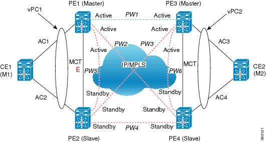
In the VPLS integration with a vPC, a customer edge (CE) device is dual-homed to two provider edge (PE) devices. The PEs are part of the VPLS domain. One of the PEs in the VPLS domain is in Active state and forwards traffic, while the other PE is in Standby state. See the figure below.
Figure 33-1 VPLS Integration with a vPC
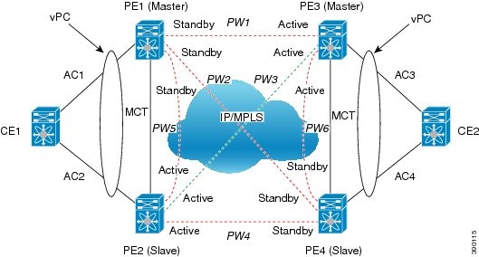
PE1 and PE2 belong to a vPC domain. PE3 and PE4 are part of another vPC domain. In addition to being part of their respective vPC domains, VPLS is configured on the PEs using a mesh of PWs.
In the above figure, the virtual forwarding instance (VFI) configured under a particular VLAN in PE2 is Active for vPC group (PE1, PE2) and VFI configured under a particular VLAN in PE3 is Active for vPC group (PE3, PE4). The Active VFI advertises the local status of Active on all the PWs. The Standby VFI advertises the local status of Standby on all the PWs. A PW is Active when both ends advertise the status of Active. Therefore, PW3 is Active between PE2 and PE3 and is used to carry traffic between CE1 and CE2.
The VPLS domain is configured in decoupled mode. As a result, the status of the AC links is not advertised to the PWs.
Overview of a vPC Peer Link
You can have only two switches as vPC peers; each switch can serve as a vPC peer to only one other vPC peer. The vPC peer switches can also have non-vPC links to other switches.
To create a valid configuration, you must configure an EtherChannel on each switch and then configure the vPC domain. You must assign the EtherChannel on each switch as a peer link. For redundancy, we recommend that you configure at least two dedicated ports into the EtherChannel; if one of the interfaces in the vPC peer link fails, the switch automatically falls back to use another interface in the peer link.

Note![]() The two switches connected by the vPC peer link have certain identical operational and configuration parameters.
The two switches connected by the vPC peer link have certain identical operational and configuration parameters.
When you configure the vPC peer link, the vPC peer switches negotiate that one of the connected switches is the primary switch and the other connected switch is the secondary switch. By default, Cisco NX-OS software uses the lowest MAC address to elect the primary switch. The software takes different actions on each switch only in certain failover conditions. If the primary switch fails, the secondary switch becomes the operational primary switch when the system recovers, and the previously primary switch becomes the secondary switch.
MAC addresses that are learned over vPC links are synchronized between the peers. Configuration information flows across the vPC peer link using the Cisco Fabric Services over Ethernet (CFSoE) protocol. All MAC addresses for VLANs configured on both switches are synchronized between vPC peer switches. The software uses CFSoE for this synchronization.
If the vPC peer link fails, the software checks the status of the remote vPC peer switch by using the peer-keepalive link, which is a link between vPC peer switches, to ensure that both switches are up. If the vPC peer switch is up, the secondary vPC switch disables all vPC ports on its switch. The data then forwards the remaining active links of the EtherChannel. The software learns of a vPC peer switch failure when the keepalive messages are not returned over the peer-keepalive link. Use a separate link (vPC peer-keepalive link) to send configurable keepalive messages between the vPC peer switches. The keepalive messages on the vPC peer-keepalive link determines whether a failure is on the vPC peer link only or on the vPC peer switch. The keepalive messages are used only when all the links in the peer link fail.
Validating the Configuration Between Switches
Cisco NX-OS software validates the configuration between primary (master) and secondary (slave) switches. When a Type-1 mismatch occurs between the primary and secondary switches for a particular VLAN, the VLAN is suspended on both the switches. When a consistency check fails, only the secondary virtual port channel (vPC) switch is brought down. The VLAN remains up on the primary switch and Type-1 configurations can be performed without traffic disruption.
The virtual forwarding instance (VFI) on the vPC switch can be configured as primary or secondary, independent of the vPC state (master or slave) on the switch. Similarly, the VFI on the other vPC switch can be configured as primary or secondary; just not the same as the other vPC peer. If both the vPC peers are configured as primary or secondary or if no primary or secondary vPC peer is configured, a Type-1 error occurs. The table below summarizes the configurations to be avoided.
|
|
|
|---|---|
Port, Link, and Node Failures
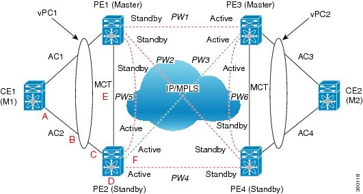
The VPLS Active-Standby Support with a vPC feature provides network resiliency by protecting against port, link, and node failures. These failures can be categorized into the following scenarios:
- Scenario A: Failure of the uplink port on the dual-homed device (DHD)
- Scenario B: Failure of the uplink (AC) of the DHD
- Scenario C: Failure of the port on a vPC peer
- Scenario D: Failure of the primary node in vPC
- Scenario E: Failure of the vPC peer link (MCT)
- Scenario F: Failure of the vPC node uplink towards the MPLS core
These failure points are shown in the figure below.
Figure 33-2 Port, Link, and Node Failures
Failed Port or AC Link
The figure below shows the frame flow if a port on the DHD or vPC peer or the attachment circuit (AC) link fails (scenario A, B, or C).
Figure 33-3 Failure Scenario A, B, or C
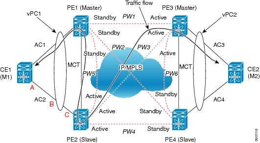
For A, B, or C failures, a vPC diverts the traffic destined from PE2 to AC2 toward multichassis trunk (MCT). In case of A, B, or C failures, PE2 sends a message to PE1 to forward the traffic that is received over MCT to vPC links in addition to sending it over non-vPC links. The traffic is forwarded on AC1 and is received or sent by CE1.
In all of these failure scenarios, because VPLS is configured in decoupled mode, PE2 continues to advertise the local status of Active on all its PWs, and PE1 continues to advertise the local status of Standby.
Failed Primary Node
The figure below shows the switch configured as the primary node fails (scenario D).
Figure 33-4 Failure Scenario D
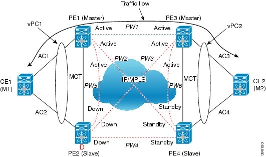
If the primary node in the vPC fails, the peer vPC node detects the failure and starts advertising its local status of Active on all core PWs. PW1 between PE1 and PE3 becomes the Active PW and traffic between vPC1 and vPC2 flows over PW1. If PE3 detects that PW3 to PE2 is down before PE1 has advertised the local status of Active, traffic is dropped by PE3 toward the core (that was using PW3) until PE3 receives the status of Active from PE1.
Failed vPC Peer Link
The figure below shows scenario E or the failure of vPC peer link, also known as multichassis trunk (MCT).
Figure 33-5 Failure Scenario E
If MCT fails and both the nodes in the virtual port channel (vPC) are still up, the vPC master node keeps the AC link up and the vPC slave node brings its AC link down.
Because VPLS is configured in decoupled mode (the status of the AC link is not advertised to the core pseudowires), the Standby PE2 advertises the local status of Standby to all the core pseudowires (PWs) even though AC2 is down. Therefore, the traffic between vPC1 and vPC2 flows over PW1. The traffic between CE1 and PE1 flows only through the AC1 link.
You can configure vPC to detect a double fault if both MCT and the primary vPC node fail. You can configure vPC by using the out-of-band keepalive mechanism. In this scenario, the secondary vPC node keeps the AC link (AC) up and PE2 continues to advertise the status of Active to all core PWs. PW3 remains active.
Failed Core Pseudowires
The figure below shows the failure of core pseudowires (PWs) on the Active vPC node (scenario F).
Figure 33-6 Failure Scenario F
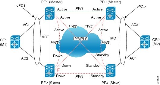
When all PWs in the core on the Active vPC node go down, the peer Standby vPC node changes its state to Active and advertises the local status of Active on all core PWs. PW 1 becomes Active.
When all core interfaces on a node go down, the PWs in the VPLS domain also go down.
Licensing for Layer 2 VPN VPLS Dual-Homing with a vPC
The following table shows the licensing requirements for this feature:
Guidelines and Limitations for Layer 2 VPN VPLS Dual-Homing with a vPC
The VPLS Dual-Homing with a vPC feature is supported only on switch port links. Virtual port channel (vPC) is not supported on an Ethernet virtual circuit (EVC) port.
Configuring Layer 2 VPN VPLS Dual-Homing with a vPC
You can configure a vPC peer as the primary node in a dual-homed topology. Repeat this task to configure the other vPC peer as the secondary node.
Before You Begin
SUMMARY STEPS
2.![]() [ no ] l2vpn vfi context vfi-name
[ no ] l2vpn vfi context vfi-name
3.![]() (Optional) description description
(Optional) description description
5.![]() redundancy { primary | secondary }
redundancy { primary | secondary }
6.![]() member ip-address encapsulation mpls
member ip-address encapsulation mpls
DETAILED STEPS
Configuration Examples for Layer 2 VPN VPLS Dual-Homing with a vPC
Additional References for Layer 2 VPN VPLS Dual-Homing with a vPC
Related Documents
|
|
|
|---|---|
Cisco Nexus 7000 Series NX-OS Layer 2 Switching Command Reference |
|
“Configuring vPCs” chapter of the Cisco Nexus 7000 Series NX-OS Interfaces Configuration Guide |
Feature History for Layer 2 VPN VPLS Dual-Homing with a vPC
Table 33-1 lists the history for this feature.
 Feedback