- New and Changed Information
- Preface
- Cisco DCNM Introduction
- Part 1: Cisco DCNM-SAN Installation
- Preparing Cisco DCNM-SAN Client
- Installing Cisco DCNM-SAN Database
- Installing Cisco DCNM-SAN
- Maintaining Cisco DCNM-SAN
- Uninstalling Cisco DCNM-SAN
- Licensing Cisco DCNM-SAN
- Part 2: Cisco DCNM-LAN Installation
- Deploying Cisco DCNM-LAN
- Preparing Cisco DCNM-LAN Database
- Installing Cisco DCNM-LAN Servers
- Licensing Cisco DCNM-LAN Deployment
- Upgrading Cisco DCNM-LAN Servers
- Configuring Cisco DCNM-LAN Servers
- Installing and Administering Cisco DCNM VSB
- Uninstalling Cisco DCNM-LAN Servers
- Troubleshooting Cisco DCNM-LAN Server Installation
- Index
Cisco DCNM Installation and Licensing Guide, Release 5.x
Bias-Free Language
The documentation set for this product strives to use bias-free language. For the purposes of this documentation set, bias-free is defined as language that does not imply discrimination based on age, disability, gender, racial identity, ethnic identity, sexual orientation, socioeconomic status, and intersectionality. Exceptions may be present in the documentation due to language that is hardcoded in the user interfaces of the product software, language used based on RFP documentation, or language that is used by a referenced third-party product. Learn more about how Cisco is using Inclusive Language.
- Updated:
- February 2, 2012
Chapter: Preparing Cisco DCNM-SAN Client
Preparing for Installing Cisco DCNM-SAN Client
This chapter describes about the prerequisites for installing DCNM-SAN components and contains the following sections:
Information About Cisco MDS 9000 Switch Management and DCNM-SAN
The Cisco DCNM-SAN is a set of network management tools that supports Secure Simple Network Management Protocol version 3 (SNMPv3). It provides a graphical user interface (GUI) that displays real-time views of your network fabrics, and lets you manage the configuration of Cisco MDS 9000 Family devices and third-party switches. The Cisco DCNM-SAN provides an alternative to the command-line interface (CLI) for most switch configuration commands.
In addition to complete configuration and status monitoring capabilities for Cisco MDS 9000 switches, DCNM-SAN provides powerful Fibre Channel troubleshooting tools. These in-depth health and configuration analysis capabilities leverage unique MDS 9000 switch capabilities: Fibre Channel Ping and Traceroute.
This section includes the following topics:
- Cisco MDS 9000 Switch Management
- Storage Management Solutions Architecture
- In-Band Management and Out-of-Band Management
- Cisco DCNM-SAN
Cisco MDS 9000 Switch Management
The Cisco MDS 9000 Family of switches can be accessed and configured in many different ways and supports standard management protocols. Table 1-1 lists the management protocols that DCNM-SAN supports to access, monitor, and configure the Cisco MDS 9000 Family of switches.
Storage Management Solutions Architecture
Management services required for the storage environment can be divided into five layers, with the bottom layer being closest to the physical storage network equipment, and the top layer managing the interface between applications and storage resources.
Of these five layers of storage network management, Cisco DCNM-SAN provides tools for device (element) management and fabric management. In general, the Device Manager is most useful for device management (a single switch), while DCNM-SAN is more efficient for performing fabric management operations involving multiple switches.
Tools for upper-layer management tasks can be provided by Cisco or by third-party storage and network management applications. The following summarizes the goals and function of each layer of storage network management:
- Device management provides tools to configure and manage a device within a system or a fabric. You use device management tools to perform tasks on one device at a time, such as initial device configuration, setting and monitoring thresholds, and managing device system images or firmware.
- Fabric management provides a view of an entire fabric and its devices. Fabric management applications provide fabric discovery, fabric monitoring, reporting, and fabric configuration.
- Resource management provides tools for managing resources such as fabric bandwidth, connected paths, disks, I/O operations per second (IOPS), CPU, and memory. You can use DCNM-SAN to perform some of these tasks.
- Data management provides tools for ensuring the integrity, availability, and performance of data. Data management services include redundant array of independent disks (RAID) schemes, data replication practices, backup or recovery requirements, and data migration. Data management capabilities are provided by third-party tools.
- Application management provides tools for managing the overall system consisting of devices, fabric, resources, and data from the application. Application management integrates all these components with the applications that use the storage network. Application management capabilities are provided by third-party tools.
In-Band Management and Out-of-Band Management
Cisco DCNM-SAN requires an out-of-band (Ethernet) connection to at least one Cisco MDS 9000 Family switch. You need either mgmt0 or IP over Fibre Channel (IPFC) to manage the fabric.
mgmt0
The out-of-band management connection is a 10/100 Mbps Ethernet interface on the supervisor module, labeled mgmt0. The mgmt0 interface can be connected to a management network to access the switch through IP over Ethernet. You must connect to at least one Cisco MDS 9000 Family switch in the fabric through its Ethernet management port. You can then use this connection to manage the other switches using in-band (Fibre Channel) connectivity. Otherwise, you need to connect the mgmt0 port on each switch to your Ethernet network.
Each supervisor module has its own Ethernet connection; however, the two Ethernet connections in a redundant supervisor system operate in active or standby mode. The active supervisor module also hosts the active mgmt0 connection. When a failover event occurs to the standby supervisor module, the IP address and media access control (MAC) address of the active Ethernet connection are moved to the standby Ethernet connection.
IPFC
You can also manage switches on a Fibre Channel network using an in-band IP connection. The Cisco MDS 9000 Family supports RFC 2625 IP over Fibre Channel, which defines an encapsulation method to transport IP over a Fibre Channel network.
IPFC encapsulates IP packets into Fibre Channel frames so that management information can cross the Fibre Channel network without requiring a dedicated Ethernet connection to each switch. This feature allows you to build a completely in-band management solution.
Cisco DCNM-SAN
The Cisco DCNM-SAN provides an alternative to the command-line interface (CLI) for most switch configuration commands. For information on using the CLI to configure a Cisco MDS 9000 Family switch, refer to the Cisco MDS 9000 Family NX-OS Fundamentsls Configuration Guide or the Cisco MDS 9020 Switch Configuration Guide and Cisco MDS 9000 Family Command Reference Guide.
In addition to complete configuration and status monitoring capabilities for Cisco MDS 9000 switches, DCNM-SAN provides powerful Fibre Channel troubleshooting tools. These in-depth health and configuration analysis capabilities leverage unique MDS 9000 switch capabilities: Fibre Channel Ping and Traceroute.
DCNM-SAN Server
The DCNM-SAN Server component must be started before running DCNM-SAN. On a Windows PC, the DCNM-SAN Server is installed as a service. This service can then be administered using the Windows Services in the Control Panel. DCNM-SAN Server is responsible for discovery of the physical and logical fabric, and for listening for SNMP traps, syslog messages, and Performance Manager threshold events.
DCNM-SAN Client
The DCNM-SAN Client component displays a map of your network fabrics, including Cisco MDS 9000 Family switches, third-party switches, hosts, and storage devices. The DCNM-SAN Client provides multiple menus for accessing the features of the DCNM-SAN Server.
Device Manager
Starting from Cisco MDS NX-OS Release 5.2(1), DCNM-SAN will automatically install Device Manager. The Device Manager provides two views of a single switch:
- Device View displays a graphic representation of the switch configuration and provides access to statistics and configuration information.
- Summary View displays a summary of xE ports (Inter-Switch Links), Fx ports (fabric ports), and Nx ports (attached hosts and storage) on the switch, as well as Fibre Channel and IP neighbor devices. Summary or detailed statistics can be charted, printed, or saved to a file in tab-delimited format.
Performance Manager
Performance Manager presents detailed traffic analysis by capturing data with SNMP. This data is compiled into various graphs and charts that can be viewed with any web browser.
DCNM Web Client
The DCNM Web Client allows operators to monitor and obtain reports for MDS events, performance, and inventory from a remote location using a web browser.
Prerequisites for Installing DCNM-SAN
This section includes the following topics:
- Initial Setup Routine
- Preparing to Configure the Switch
- Default Login
- Setup Options
- Assigning Setup Information
- Enter the switch name: switch_name
- Starting a Switch in the Cisco MDS 9000 Family
- Accessing the Switch
Initial Setup Routine
The first time you access a switch in the Cisco MDS 9000 Family, it runs a setup program that prompts you for the IP address and other configuration information necessary for the switch to communicate over the supervisor module Ethernet interface. This information is required to configure and manage the switch. The IP address can only be configured from the CLI. All Cisco MDS 9000 Family switches have the network administrator as a default user (admin). You cannot change the default user at any time. You must explicitly configure a strong password for any switch in the Cisco MDS 9000 Family. The setup scenario differs based on the subnet to which you are adding the new switch:
- Out-of-band management—This feature provides a connection to the network through a supervisor module front panel Ethernet port.
- In-band management—This feature provides IP over Fibre Channel (IPFC) to manage the switches. The in-band management feature is transparent to the network management system (NMS).
The first time that you access a switch in the Cisco MDS 9000 Family using the CLI, it runs a setup program that prompts you for the IP address and other configuration information necessary for the switch to communicate over the supervisor module Ethernet interface. This information is required to configure and manage the switch.

Note![]() The IP address can only be configured from the CLI. When you power up the switch for the first time, assign the IP address. After you perform this step, the Cisco MDS 9000 Family DCNM-SAN can reach the switch through the management port.
The IP address can only be configured from the CLI. When you power up the switch for the first time, assign the IP address. After you perform this step, the Cisco MDS 9000 Family DCNM-SAN can reach the switch through the management port.
Preparing to Configure the Switch
Before you configure a switch in the Cisco MDS 9000 Family for the first time, you need the following information:
–![]() Creating a password for the administrator (required).
Creating a password for the administrator (required).
–![]() Creating an additional login account and password (optional).
Creating an additional login account and password (optional).
- IP address for the switch management interface—The management interface can be an out-of-band Ethernet interface or an in-band Fibre Channel interface (recommended).
- Subnet mask for the switch's management interface (optional).
- IP addresses, including:
–![]() Destination prefix, destination prefix subnet mask, and next hop IP address, if you want to enable IP routing. Also, provide the IP address of the default network (optional).
Destination prefix, destination prefix subnet mask, and next hop IP address, if you want to enable IP routing. Also, provide the IP address of the default network (optional).
–![]() Otherwise, provide an IP address of the default gateway (optional).
Otherwise, provide an IP address of the default gateway (optional).
- SSH service on the switch—To enable this optional service, select the type of SSH key (dsa/rsa/rsa1) and number of key bits (768 to 2048).
- DNS IP address (optional).
- Default domain name (optional).
- NTP server IP address (optional).
- SNMP community string (optional).
- Switch name—This is your switch prompt (optional).
Note![]() Be sure to configure the IP route, the IP default network address, and the IP default gateway address to enable SNMP access. If IP routing is enabled, the switch uses the IP route and the default network IP address. If IP routing is disabled, the switch uses the default gateway IP address.
Be sure to configure the IP route, the IP default network address, and the IP default gateway address to enable SNMP access. If IP routing is enabled, the switch uses the IP route and the default network IP address. If IP routing is disabled, the switch uses the default gateway IP address.
Note![]() You should verify that the DCNM-SAN Server hostname entry exists on the DNS server, unless the DCNM-SAN Server is configured to bind to a specific interface during installation.
You should verify that the DCNM-SAN Server hostname entry exists on the DNS server, unless the DCNM-SAN Server is configured to bind to a specific interface during installation.
Default Login
All Cisco MDS 9000 Family switches have the network administrator as a default user (admin). You cannot change the default user at any time (see the Cisco DCNM for SAN Security Configuration Guide).
You have an option to enforce secure password for any switch in the Cisco MDS 9000 Family. If a password is trivial (short, easy-to-decipher), your password configuration is rejected. Be sure to configure a secure password (see the Cisco DCNM for SAN Security Configuration Guide). If you configure and subsequently forget this new password, you have the option to recover this password (see the Cisco DCNM for SAN Security Configuration Guide).
Setup Options
The setup scenario differs based on the subnet to which you are adding the new switch. You must configure a Cisco MDS 9000 Family switch with an IP address to enable management connections from outside of the switch.
Note![]() Some concepts such as out-of-band management and in-band management are briefly explained here. These concepts are explained in more detail in subsequent chapters.
Some concepts such as out-of-band management and in-band management are briefly explained here. These concepts are explained in more detail in subsequent chapters.
- Out-of-band management—This feature provides a connection to the network through a supervisor module front panel Ethernet port (see Figure 1-1).
- In-band management—This feature provides IP over Fibre Channel (IPFC) to manage the switches. The in-band management feature is transparent to the network management system (NMS). Instead of conventional Ethernet physical media, switches in the Cisco MDS 9000 Family use IPFC as the transport mechanism. see Cisco DCNM for SAN IP Services Configuration Guide.
Figure 1-1 Management Access to Switches
Assigning Setup Information
This section describes how to initially configure the switch for both out-of-band and in-band management.
Note![]() Press Ctrl-C at any prompt to skip the remaining configuration options and proceed with what is configured until that point. Entering a new password for the administrator is a requirement and cannot be skipped.
Press Ctrl-C at any prompt to skip the remaining configuration options and proceed with what is configured until that point. Entering a new password for the administrator is a requirement and cannot be skipped.

Tip![]() If you do not wish to answer a previously configured question, or if you wish to skip answers to any questions, press Enter. If a default answer is not available (for example, switch name), the switch uses what was previously configured and skips to the next question.
If you do not wish to answer a previously configured question, or if you wish to skip answers to any questions, press Enter. If a default answer is not available (for example, switch name), the switch uses what was previously configured and skips to the next question.
Configuring Out-of-Band Management
Note![]() You can configure both in-band and out-of-band configuration together by entering Yes in both Step 11c and Step 11d in the following procedure.
You can configure both in-band and out-of-band configuration together by entering Yes in both Step 11c and Step 11d in the following procedure.
To configure the switch for first time out-of-band access, follow these steps:
Step 1![]() Power on the switch. Switches in the Cisco MDS 9000 Family boot automatically.
Power on the switch. Switches in the Cisco MDS 9000 Family boot automatically.
Step 2![]() Enter Yes to enforce secure password.
Enter Yes to enforce secure password.
a.![]() Enter the administrator password
Enter the administrator password
b.![]() Confirm the administrator password.
Confirm the administrator password.
Tip If a password is trivial (short, easy to decipher), your password configuration is rejected. Be sure to configure a secure password as shown in the sample configuration. Passwords are case-sensitive. You must explicitly configure a password that meets the requirements listed in the Cisco DCNM for SAN Security Configuration Guide.
Step 3![]() Enter yes to enter the setup mode.
Enter yes to enter the setup mode.
Note![]() This setup utility will guide you through the basic configuration of the system. Setup configures only enough connectivity for management of the system.
This setup utility will guide you through the basic configuration of the system. Setup configures only enough connectivity for management of the system.
The setup utility guides you through the basic configuration process. Press Ctrl-C at any prompt to end the configuration process.
Step 4![]() Enter the new password for the administrator (admin is the default).
Enter the new password for the administrator (admin is the default).
Step 5![]() Enter yes (no is the default) to create additional accounts.
Enter yes (no is the default) to create additional accounts.
While configuring your initial setup, you can create an additional user account (in the network-admin role) besides the administrator’s account. See the Cisco DCNM for SAN Security Configuration Guide for information on default roles and permissions.
Note![]() User login IDs must contain non-numeric characters.
User login IDs must contain non-numeric characters.
a.![]() Enter the user login ID [administrator].
Enter the user login ID [administrator].
c.![]() Confirm the user password for
Confirm the user password for
Step 6![]() Enter yes (no is the default) to create an SNMPv3 account.
Enter yes (no is the default) to create an SNMPv3 account.
a.![]() Enter the user name (admin is the default).
Enter the user name (admin is the default).
b.![]() Enter the SNMPv3 password (minimum of eight characters). The default is admin123.
Enter the SNMPv3 password (minimum of eight characters). The default is admin123.
Step 7![]() Enter yes (no is the default) to configure the read-only or read-write SNMP community string.
Enter yes (no is the default) to configure the read-only or read-write SNMP community string.
a.![]() Enter the SNMP community string.
Enter the SNMP community string.
Step 8![]() Enter a name for the switch.
Enter a name for the switch.
Step 9![]() Enter yes (yes is the default) to configure out-of-band management.
Enter yes (yes is the default) to configure out-of-band management.
a.![]() Enter the mgmt0 IP address.
Enter the mgmt0 IP address.
b.![]() Enter the mgmt0 subnet mask.
Enter the mgmt0 subnet mask.
Step 10![]() Enter yes (yes is the default) to configure the default gateway (recommended).
Enter yes (yes is the default) to configure the default gateway (recommended).
a.![]() Enter the default gateway IP address.
Enter the default gateway IP address.
Step 11![]() Enter yes (no is the default) to configure advanced IP options such as in-band management, static routes, default network, DNS, and domain name.
Enter yes (no is the default) to configure advanced IP options such as in-band management, static routes, default network, DNS, and domain name.
a.![]() Enter no (no is the default) at the in-band management configuration prompt.
Enter no (no is the default) at the in-band management configuration prompt.
b.![]() Enter yes (no is the default) to enable IP routing capabilities.
Enter yes (no is the default) to enable IP routing capabilities.
c.![]() Enter yes (no is the default) to configure a static route (recommended).
Enter yes (no is the default) to configure a static route (recommended).
Type the destination prefix mask.
Note![]() Be sure to configure the IP route, the default network IP address, and the default gateway IP address to enable SNMP access. If IP routing is enabled, the switch uses the IP route and the default network IP address. If IP routing is disabled, the switch uses the default gateway IP address.
Be sure to configure the IP route, the default network IP address, and the default gateway IP address to enable SNMP access. If IP routing is enabled, the switch uses the IP route and the default network IP address. If IP routing is disabled, the switch uses the default gateway IP address.
d.![]() Enter yes (no is the default) to configure the default network (recommended).
Enter yes (no is the default) to configure the default network (recommended).
Enter the default network IP address.
Note![]() The default network IP address is the destination prefix provided in Step 11c .
The default network IP address is the destination prefix provided in Step 11c .
e.![]() Enter yes (no is the default) to configure the DNS IP address.
Enter yes (no is the default) to configure the DNS IP address.
f.![]() Enter yes (default is no) to configure the default domain name.
Enter yes (default is no) to configure the default domain name.
Enter the default domain name.
Step 12![]() Enter yes (no is the default) to enable Telnet service.
Enter yes (no is the default) to enable Telnet service.
Step 13![]() Enter yes (no is the default) to enable the SSH service.
Enter yes (no is the default) to enable the SSH service.
Step 14![]() Enter the SSH key type.
Enter the SSH key type.
Step 15![]() Enter the number of key bits within the specified range.
Enter the number of key bits within the specified range.
Step 16![]() Enter yes (no is the default) to configure the NTP server.
Enter yes (no is the default) to configure the NTP server.
a.![]() Enter the NTP server IP address.
Enter the NTP server IP address.
Step 17![]() Enter noshut (shut is the default) to configure the default switch port interface to the shut state.
Enter noshut (shut is the default) to configure the default switch port interface to the shut state.
Step 18![]() Enter on (on is the default) to configure the switch port trunk mode.
Enter on (on is the default) to configure the switch port trunk mode.
Step 19![]() Enter no (no is the default) to configure switchport port mode F.
Enter no (no is the default) to configure switchport port mode F.
Step 20![]() Enter permit (deny is the default) to deny a default zone policy configuration.
Enter permit (deny is the default) to deny a default zone policy configuration.
Permits traffic flow to all members of the default zone.
Step 21![]() Enter yes (no is the default) to disable a full zone set distribution (see the Cisco DCNM for SAN Fabric Configuration Guide). Disables the switch-wide default for the full zone set distribution feature.
Enter yes (no is the default) to disable a full zone set distribution (see the Cisco DCNM for SAN Fabric Configuration Guide). Disables the switch-wide default for the full zone set distribution feature.
You see the new configuration. Review and edit the configuration that you have just entered.
Step 22![]() Enter no (no is the default) if you are satisfied with the configuration.
Enter no (no is the default) if you are satisfied with the configuration.
Step 23![]() Enter yes (yes is default) to use and save this configuration:
Enter yes (yes is default) to use and save this configuration:

Configuring In-Band Management
The in-band management logical interface is VSAN 1. This management interface uses the Fibre Channel infrastructure to transport IP traffic. An interface for VSAN 1 is created on every switch in the fabric. Each switch should have its VSAN 1 interface configured with an IP address in the same subnetwork. A default route that points to the switch providing access to the IP network should be configured on every switch in the Fibre Channel fabric (see Cisco Fabric Manager Fabric Configuration Guide)
Note![]() You can configure both in-band and out-of-band configuration together by entering Yes in both Step 9c and Step 9d in the following procedure.
You can configure both in-band and out-of-band configuration together by entering Yes in both Step 9c and Step 9d in the following procedure.
To configure a switch for first time in-band access, follow these steps:
Step 1![]() Power on the switch. Switches in the Cisco MDS 9000 Family boot automatically.
Power on the switch. Switches in the Cisco MDS 9000 Family boot automatically.
Step 2![]() Enter the new password for the administrator.
Enter the new password for the administrator.
Tip If a password is trivial (short, easy-to-decipher), your password configuration is rejected. Be sure to configure a strong password as shown in the sample configuration. Passwords are case-sensitive. You must explicitly configure a password that meets the requirements listed in the User Accounts section in Cisco DCNM for SAN Security Configuration Guide.
Step 3![]() Enter yes to enter the setup mode.
Enter yes to enter the setup mode.
The setup utility guides you through the basic configuration process. Press Ctrl-C at any prompt to end the configuration process.
Step 4![]() Enter no (no is the default) if you do not wish to create additional accounts.
Enter no (no is the default) if you do not wish to create additional accounts.
Step 5![]() Configure the read-only or read-write SNMP community string.
Configure the read-only or read-write SNMP community string.
a.![]() Enter no (no is the default) to avoid configuring the read-only SNMP community string.
Enter no (no is the default) to avoid configuring the read-only SNMP community string.
Step 6![]() Enter a name for the switch.
Enter a name for the switch.
Note![]() The switch name is limited to 32 alphanumeric characters. The default is switch.
The switch name is limited to 32 alphanumeric characters. The default is switch.
Step 7![]() Enter no (yes is the default) at the configuration prompt to configure out-of-band management.
Enter no (yes is the default) at the configuration prompt to configure out-of-band management.
Step 8![]() Enter yes (yes is the default) to configure the default gateway.
Enter yes (yes is the default) to configure the default gateway.
a.![]() Enter the default gateway IP address.
Enter the default gateway IP address.
Step 9![]() Enter yes (no is the default) to configure advanced IP options such as in-band management, static routes, default network, DNS, and domain name.
Enter yes (no is the default) to configure advanced IP options such as in-band management, static routes, default network, DNS, and domain name.
a.![]() Enter yes (no is the default) at the in-band management configuration prompt.
Enter yes (no is the default) at the in-band management configuration prompt.
b.![]() Enter no (yes is the default) to enable IP routing capabilities.
Enter no (yes is the default) to enable IP routing capabilities.
c.![]() Enter no (yes is the default) to configure a static route.
Enter no (yes is the default) to configure a static route.
d.![]() Enter no (yes is the default) to configure the default network.
Enter no (yes is the default) to configure the default network.
e.![]() Enter no (yes is the default) to configure the DNS IP address.
Enter no (yes is the default) to configure the DNS IP address.
f.![]() Enter no (no is the default) to skip the default domain name configuration.
Enter no (no is the default) to skip the default domain name configuration.
Step 10![]() Enter no (yes is the default) to disable Telnet service.
Enter no (yes is the default) to disable Telnet service.
Step 11![]() Enter yes (no is the default) to enable the SSH service.
Enter yes (no is the default) to enable the SSH service.
Step 12![]() Enter the SSH key type (see the Cisco DCNM for SAN Security Configuration Guide) that you would like to generate.
Enter the SSH key type (see the Cisco DCNM for SAN Security Configuration Guide) that you would like to generate.
Step 13![]() Enter the number of key bits within the specified range.
Enter the number of key bits within the specified range.
Step 14![]() Enter no (no is the default) to configure the NTP server.
Enter no (no is the default) to configure the NTP server.
Step 15![]() Enter shut (shut is the default) to configure the default switch port interface to the shut state.
Enter shut (shut is the default) to configure the default switch port interface to the shut state.
Note![]() The management Ethernet interface is not shut down at this point—only the Fibre Channel, iSCSI, FCIP, and Gigabit Ethernet interfaces are shut down.
The management Ethernet interface is not shut down at this point—only the Fibre Channel, iSCSI, FCIP, and Gigabit Ethernet interfaces are shut down.
Step 16![]() Enter auto (off is the default) to configure the switch port trunk mode.
Enter auto (off is the default) to configure the switch port trunk mode.
Step 17![]() Enter deny (deny is the default) to deny a default zone policy configuration.
Enter deny (deny is the default) to deny a default zone policy configuration.
Denies traffic flow to all members of the default zone.
Step 18![]() Enter no (no is the default) to disable a full zone set distribution.
Enter no (no is the default) to disable a full zone set distribution.
Disables the switch-wide default for the full zone set distribution feature.
You see the new configuration. Review and edit the configuration that you have just entered.
Step 19![]() Enter no (no is the default) if you are satisfied with the configuration.
Enter no (no is the default) if you are satisfied with the configuration.
Step 20![]() Enter yes (yes is default) to use and save this configuration.
Enter yes (yes is default) to use and save this configuration.
Using the setup Command
To make changes to the initial configuration at a later time, you can issue the setup command in EXEC mode.
The setup utility guides you through the basic configuration process.
Starting a Switch in the Cisco MDS 9000 Family
The following procedure is a review of the tasks you should have completed during hardware installation, including starting up the switch. These tasks must be completed before you can configure the switch.
Note![]() You must use the CLI for initial switch start up.
You must use the CLI for initial switch start up.
Before you can configure a switch, follow these steps:
Step 1![]() Verify the following physical connections for the new Cisco MDS 9000 Family switch:
Verify the following physical connections for the new Cisco MDS 9000 Family switch:
- The console port is physically connected to a computer terminal (or terminal server).
- The management 10/100 Ethernet port (mgmt0) is connected to an external hub, switch, or router.
Refer to the Cisco MDS 9000 Family Hardware Installation Guide (for the required product) for more information.
Tip Save the host ID information for future use (for example, to enable licensed features). The host ID information is provided in the Proof of Purchase document that accompanies the switch.
Step 2![]() Verify that the default console port parameters are identical to those of the computer terminal (or terminal server) attached to the switch console port:
Verify that the default console port parameters are identical to those of the computer terminal (or terminal server) attached to the switch console port:
Step 3![]() Power on the switch. The switch boots automatically and the switch# prompt appears in your terminal window.
Power on the switch. The switch boots automatically and the switch# prompt appears in your terminal window.
Accessing the Switch
After initial configuration, you can access the switch in one of the three ways:
- Serial console access—You can use a serial port connection to access the CLI.
- In-band IP (IPFC) access—You can use Telnet or SSH to access a switch in the Cisco MDS 9000 Family or use SNMP to connect to a Cisco MDS 9000 DCNM-SAN application.
- Out-of-band (10/100BASE-T Ethernet) access—You can use Telnet or SSH to access a switch in the Cisco MDS 9000 Family or use SNMP to connect to a Cisco MDS 9000 DCNM-SAN application.
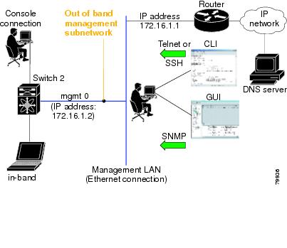
After initial configuration, you can access the switch in one of three ways (see Figure 1-2):
- Serial console access—You can use a serial port connection to access the CLI.
- In-band IP (IPFC) access—You can use Telnet or SSH to access a switch in the Cisco MDS 9000 Family or use Cisco MDS 9000 DCNM-SAN to access the switch.
- Out-of-band (10/100BASE-T Ethernet) access—You can use Telnet or SSH to access a switch in the Cisco MDS 9000 Family or use Cisco MDS 9000 DCNM-SAN to access the switch.
Figure 1-2 Switch Access Options
Where Do You Go Next?
After reviewing the default configuration, you can change it or perform other configuration or management tasks. The initial setup can only be performed at the CLI. However, you can continue to configure other software features, or access the switch after initial configuration by using either the CLI or the Device Manager and DCNM-SAN applications.
 Feedback