- First-Time Access
- Getting Started Guide Contents
- Simplified Approach to Configuring in Cisco APIC
- Installing the Cisco Application Centric Infrastructure Fabric Hardware
- Changing the BIOS Default Password
- About the APIC
- Setting up the APIC
- Provisioning IPv6 Management Addresses on APIC Controllers
- Accessing the GUI
- Accessing the REST API
- Accessing the Object Model CLI
- Accessing the NX-OS Style CLI
- Overview of the GUI
- API Inspector
Initial POD Setup and Overview
This chapter contains the following sections:
First-Time Access
Getting Started Guide Contents
The Cisco APIC Getting Started Guide contains the following information:
For detailed information about configuring the APIC, see the Cisco APIC Basic Configuration Guide. Also, see the following guides for details about installation: Cisco ACI Fabric Hardware Installation Guide and Cisco APIC Installation Guide.
Simplified Approach to Configuring in Cisco APIC
Cisco APIC supports a simplified approach to configuring the ACI with the choice of two additional user interfaces. They are the NX-OS style CLI and the Basic GUI. The existing methods of configuration using REST API and Advanced GUI are supported as well. The Advanced GUI is equivalent to the GUI of the previous releases. Cisco recommends that you use the Advanced GUI to manage any policy that you created in Release 1.2 or earlier releases.
In addition to the simple approach available for network administrators and other users of the NX-OS style CLI and the Basic GUI, there is intelligence embedded in these approaches as compared to the Advanced GUI or the REST API. In several instances, the NX-OS style CLI and the Basic GUI often create the ACI model constructs implicitly for a user's ease of use, and they also provide validations to ensure consistency in configuration. This functionality reduces and prevents faults.
Configurations using NX-OS style CLI and Basic GUI are compatible similar to the compatibility between existing methods of configuration using Advanced GUI and REST API. For further details about configurations and tasks, see the Cisco APIC Basic Configuration Guide and the Cisco APIC NX-OS Style Command-Line Interface Configuration Guide.
Installing the Cisco Application Centric Infrastructure Fabric Hardware
For details about installing the ACI fabric hardware, see the Application Centric Infrastructure Fabric Hardware Installation Guide.
Changing the BIOS Default Password
The APIC controller ships with a default BIOS password. The default password is 'password'. When the boot process starts, the boot screen displays the BIOS information on the console server.
To change the default BIOS password perform the following task:
About the APIC
The Cisco Application Centric Infrastructure (ACI) is a distributed, scalable, multitenant infrastructure with external end-point connectivity controlled and grouped through application-centric policies. The Application Policy Infrastructure Controller (APIC) is the unified point of automation, management, monitoring, and programmability for the ACI. The APIC supports the deployment, management, and monitoring of any application anywhere, with a unified operations model for the physical and virtual components of the infrastructure. The APIC programmatically automates network provisioning and control that is based on the application requirements and policies. It is the central control engine for the broader cloud network; it simplifies management and allows flexibility in how application networks are defined and automated. It also provides northbound Representational State Transfer (REST) APIs. The APIC is a distributed system that is implemented as a cluster of many controller instances.
Setting up the APIC
When the APIC is launched for the first time, the APIC console presents a series of initial setup options. For many options, you can press Enter to choose the default setting that is displayed in brackets. At any point in the setup dialog, you can restart the dialog from the beginning by pressing Ctrl-C.
Important Notes
-
If the UNIX user ID is not explicitly specified in the response from the remote authentication server, then some APIC software releases assign a default ID of 23999 to all users. If the response from the remote authentication server fails to specify a UNIX ID, all users will share the same ID of 23999 and this can result in the users being granted higher or lower privileges than the configured privileges through the RBAC policies on the APIC.
-
Cisco recommends that you assign unique UNIX user IDs in the range of 16000 to 23999 for the AV Pairs that are assigned to the users when in Bash shell (using SSH, Telnet, or Serial/KVM consoles). If a situation arises where the Cisco AV Pair does not provide a UNIX user ID, the user is assigned a user ID of 23999 or similar number from the range that also enables the user's home directories, files, and processes accessible to the remote users with a UNIX ID of 23999.
To ensure that your remote authentication server does not explicitly assign a UNIX ID in its cisco-av-pair response, open an SSH session to the APIC and log in as an administrator (using a remote user account). Once logged in, run the following commands (replace userid with the username that you logged in with):
-
admin@apic1: remoteuser-userid> cd /mit/uni/userext/remoteuser-userid
-
admin@apic1: remoteuser-userid> cat summary
-
-
If you are using a Cisco Integrated Management Controller (CIMC) for your setup, use only the port-side utility console port with the breakout cable. Setup the CIMC first, and then access the APIC through the CIMC KVM or continue to access the APIC locally through the port-side utility console port. Do not use the RJ-45 console port, unless access to the port side is restricted. If you choose the CIMC KVM access, you will have remote access available later which is required during operations.
-
If you are using RJ-45 console port, connect to CIMC using SSH and enable the Serial over LAN port using the following parameters:
-
Scope SOL sol
-
Set Enabled to Yes
-
Commit
-
Exit
After enabling, enter the command connect host to access the console. If the serial port is connected, either disconnect the serial port or ensure that the connected device has the proper configuration.
-
-
It is recommended not to modify any parameters using CIMC. If there are any issues, ensure that the default setting for CIMC management node is Dedicated Mode and not Shared. If Dedicated Mode is not used, it can prevent the discovery of fabric nodes.
-
Do not upgrade software or firmware using the CIMC user interface, XML, or SSH interfaces unless the modified property and software or firmware version are supported with your specific APIC version.
-
Set the NIC mode to Dedicated, when setting up the CIMC, in the CIMC Configuration Utility. After the CIMC is configured, in the CIMC GUI, verify that you have the following parameters set.
Parameters
Settings
LLDP
Disabled on the VIC
TPM Support
Enabled on the BIOS
TPM Enabled Status
Enabled
TPM Ownership
Owned
-
Starting with APIC release 1.2(2x), during the initial setup the system will prompt you to select IPv4, or IPv6, or dual stack configuration. Choosing dual stack will enable accessing the APIC and ACI fabric out-of-band management interfaces with either IPv4 or IPv6 addresses. While the examples in the table below use IPv4 addresses, you can use whatever IP address configuration options you chose to enable during the initial setup.
-
A minimum subnet mask of /19 is recommended.
-
Connecting the APIC (the controller cluster) to the ACI fabric requires a 10G interface on the ACI leaf. You cannot connect the APIC directly to the N9332PQ ACI leaf switch, unless you use a 40G to 10G converter (part number CVR-QSFP-SFP10G), in which case the port on the N9332PQ switch will auto-negotiate to 10G without requiring any manual configuration.
-
The fabric ID is set during the APIC controller setup and it cannot be changed unless you perform a clean reload of the fabric. To change the fabric ID, perform a clean reload on the APIC and leaf switches after changing the sam.config file. You must have separate fabric IDs if you want to connect two ACI fabric domains using Layer 2 links. This follows the dual-fabric design.
About High Availability for APIC Cluster
The High Availability functionality for an APIC cluster enables you to operate the APICs in a cluster in an active/standby mode. In an APIC cluster, the designated active APICs share the load and the designated standby APICs can act as an replacement for any of the APICs in an active cluster.
An admin user can set up the High Availability functionality when the APIC is launched for the first time. It is recommended that you have at least 3 active APICs in a cluster, and one or more standby APICs. An admin user will have to initiate the switch over to replace an active APIC with a standby APIC. See the Cisco APIC Management, Installation, Upgrade, and Downgrade Guide for more information.
| Name | Description | Default Value | ||
|---|---|---|---|---|
|
Fabric name |
Fabric domain name |
ACI Fabric1 |
||
|
Fabric ID |
Fabric ID |
1 |
||
|
Number of active controllers |
Cluster size |
3
|
||
|
POD ID |
POD ID |
1 |
||
|
Standby controller |
Setup standby controller |
NO |
||
|
Controller ID |
Unique ID number for the active APIC instance. |
Valid range: 1-19 |
||
|
Controller name |
Active controller name |
apic1 |
||
|
IP address pool for tunnel endpoint addresses |
Tunnel endpoint address pool |
10.0.0.0/16 This value is for the infrastructure virtual routing and forwarding (VRF) only. This subnet should not overlap with any other routed subnets in your network. If this subnet does overlap with another subnet, change this subnet to a different /16 subnet. The minimum supported subnet for a 3 APIC cluster is /23. If you are using Release 2.0(1) the minimum is /22. |
||
|
VLAN ID for infrastructure network1 |
Infrastructure VLAN for APIC-to-switch communication including virtual switches
|
-- |
||
|
IP address pool for bridge domain multicast address (GIPo) |
IP addresses used for fabric multicast . For Cisco APIC in a Cisco ACI Multi-Site topology, this GIPo address can be the same across sites. |
225.0.0.0/15 Valid range: 225.0.0.0/15 to 231.254.0.0/15, prefixlen must be 15 (128k IPs) |
||
|
IPv4/IPv6 addresses for the out-of-band management |
IP address that you use to access the APIC through the GUI, CLI, or API. This address must be a reserved address from the VRF of a customer |
— |
||
|
IPv4/IPv6 addresses of the default gateway |
Gateway address for communication to external networks using out-of-band management |
— |
||
|
Management interface speed/duplex mode |
Interface speed and duplex mode for the out-of-band management interface |
auto Valid values are as follows
|
||
|
Strong password check |
Check for a strong password |
[Y] |
||
|
Password |
Password of the system administrator This password must be at least 8 characters with one special character. |
— |
| Name | Description | Default Value | ||
|---|---|---|---|---|
|
Fabric name |
Fabric domain name |
ACI Fabric1 |
||
|
Fabric ID |
Fabric ID |
1 |
||
|
Number of active controllers |
Cluster size |
3
|
||
|
POD ID |
ID of the POD |
1 |
||
|
Standby controller |
Setup standby controller |
Yes |
||
|
Standby Controller ID |
Unique ID number for the standby APIC instance . |
Recommended range: >20 |
||
|
Controller name |
Standby controller name |
NA |
||
|
IP address pool for tunnel endpoint addresses |
Tunnel endpoint address pool |
10.0.0.0/16 This value is for the infrastructure virtual routing and forwarding (VRF) only. This subnet should not overlap with any other routed subnets in your network. If this subnet does overlap with another subnet, change this subnet to a different /16 subnet. The minimum supported subnet for a 3 APIC cluster is /23. If you are using Release 2.0(1) the minimum is /22. |
||
|
VLAN ID for infrastructure network2 |
Infrastructure VLAN for APIC-to-switch communication including virtual switches
|
-- |
||
|
IPv4/IPv6 addresses for the out-of-band management |
IP address that you use to access the APIC through the GUI, CLI, or API. This address must be a reserved address from the VRF of a customer |
— |
||
|
IPv4/IPv6 addresses of the default gateway |
Gateway address for communication to external networks using out-of-band management |
— |
||
|
Management interface speed/duplex mode |
Interface speed and duplex mode for the out-of-band management interface |
auto Valid values are as follows
|
||
|
Strong password check |
Check for a strong password |
[Y] |
||
|
Password |
Password of the system administrator This password must be at least 8 characters with one special character. |
— |
Cluster configuration ...
  Enter the fabric name [ACI Fabric1]:
  Enter the fabric ID (1-128) [1]:
  Enter the number of active controllers in the fabric (1-9) [3]:
  Enter the POD ID (1-9) [1]:
  Is this a standby controller? [NO]:
  Enter the controller ID (1-3) [1]:
  Enter the controller name [apic1]: sec-ifc5
  Enter address pool for TEP addresses [10.0.0.0/16]:
  Note: The infra VLAN ID should not be used elsewhere in your environment
        and should not overlap with any other reserved VLANs on other platforms.
  Enter the VLAN ID for infra network (2-4094): 4093
  Enter address pool for BD multicast addresses (GIPO) [225.0.0.0/15]:

Out-of-band management configuration ...
  Enable IPv6 for Out of Band Mgmt Interface? [N]:
  Enter the IPv4 address [192.168.10.1/24]: 172.23.142.29/21
  Enter the IPv4 address of the default gateway [None]: 172.23.136.1
  Enter the interface speed/duplex mode [auto]:

admin user configuration ...
  Enable strong passwords? [Y]:
  Enter the password for admin:

  Reenter the password for admin:

Cluster configuration ...
  Fabric name: ACI Fabric1
  Fabric ID: 1
  Number of controllers: 3
  Controller name: sec-ifc5
  POD ID: 1
  Controller ID: 1
  TEP address pool: 10.0.0.0/16
  Infra VLAN ID: 4093
  Multicast address pool: 225.0.0.0/15

Out-of-band management configuration ...
  Management IP address: 172.23.142.29/21
  Default gateway: 172.23.136.1
  Interface speed/duplex mode: auto

admin user configuration ...
  Strong Passwords: Y
  User name: admin
  Password: ********

The above configuration will be applied ...

Warning: TEP address pool, Infra VLAN ID and Multicast address pool
         cannot be changed later, these are permanent until the
         fabric is wiped.

Would you like to edit the configuration? (y/n) [n]:
Provisioning IPv6 Management Addresses on APIC Controllers
IPv6 management addresses can be provisioned on the APIC controller at setup time or through a policy once the APIC controller is operational. Pure IPv4, Pure IPv6 or dual stack (i.e both IPv6 and IPv4 addresses) are supported. The following snippet is of a typical setup screen that describes how to setup dual stack (IPv6 and IPv4) addresses for out-of-band management interfaces during the setup:
Cluster configuration …

  Enter the fabric name [ACI Fabric1]:
  Enter the number of controllers in the fabric (1-9) [3]:
  Enter the controller ID (1-3) [1]:
  Enter the controller name [apic1]: infraipv6-ifc1
  Enter address pool for TEP addresses [10.0.0.0/16]:
  Note: The infra VLAN ID should not be used elsewhere in your environment
        and should not overlap with any other reserved VLANs on other platforms.
  Enter the VLAN ID for infra network (1-4094): 4093
  Enter address pool for BD multicast addresses (GIPO) [225.0.0.0/15]:

Out-of-band management configuration ...
  Enable IPv6 for Out of Band Mgmt Interface? [N]: Y (Enter Y to Configure IPv6 Address for Out of Band Management Address)
  Enter the IPv6 address [0:0:0:0:0:ffff:c0a8:a01/40]: 2001:420:28e:2020:0:ffff:ac1f:88e4/64 (IPv6 Address)
  Enter the IPv6 address of the default gateway  [None]: 2001:420:28e:2020:acc:68ff:fe28:b540 (IPv6 Gateway)
  Enable IPv4 also for Out of Band Mgmt Interface? [Y]: (Enter Y to Configure IPv4 Address for Out of Band Management Address)
  Enter the IPv4 address [192.168.10.1/24]: 172.31.136.228/21 (IPv4 Address)
  Enter the IPv4 address of the default gateway [None]: 172.31.136.1 (IPv4 Gateway)
  Enter the interface speed/duplex mode [auto]:

admin user configuration ...
  Enable strong passwords? [Y]:
  Enter the password for admin:

  Reenter the password for admin:
Accessing the GUI
| Step 1 | Open one of the
supported browsers:
| ||
| Step 2 | Enter the URL:
https://mgmt_ip-address
Use the out-of-band management IP address that you configured during the initial setup. For example, https://192.168.10.1.
| ||
| Step 3 | When the login screen appears, enter the administrator name and password that you configured during the initial setup. | ||
| Step 4 | In the
Domain field, from the drop-down list, choose
the appropriate domain that is defined.
If multiple login domains are defined, the Domain field is displayed. If the user does not choose a domain, the DefaultAuth login domain is used for authentication by default. This may result in login failure if the username is not in the DefaultAuth login domain. | ||
| Step 5 | In the Mode field, from the drop-down list, choose the Advanced or the Basic mode as desired. |
What to Do Next
To learn about the features and operation of the Application Centric Infrastructure fabric and the Application Policy Infrastructure Controller, see the available white papers and the Cisco Application Centric Infrastructure Fundamentals Guide.
Accessing the REST API
Use the out-of-band management IP address that you configured during the initial setup.
|
Accessing the Object Model CLI
 Note | From Cisco APIC Release 1.0 until Release 1.2, the default CLI was a Bash shell with commands to directly operate on managed objects (MOs) and properties of the Management Information Model. Beginning with Cisco APIC Release 1.2, the default CLI is a NX-OS style CLI. The object model CLI is available by typing the bash command at the initial CLI prompt. |
| Step 1 | From a secure
shell (SSH) client, open an SSH connection to
username@ip-address.
Use the administrator login name and the out-of-band management IP address that you configured during the initial setup. For example, ssh admin@192.168.10.1. |
| Step 2 | When prompted,
enter the administrator password that you configured during the initial setup.
With Cisco APIC Releases 1.0 and 1.1, you are now in the object model CLI. With Cisco APIC Release 1.2, you are now in the NX-OS style CLI for APIC. |
| Step 3 | With Cisco APIC
Release 1.2, type
bash to enter
the object model CLI.
This example shows how to enter the object model CLI and how to return to the NX-OS style CLI: $ ssh admin@192.168.10.1 Application Policy Infrastructure Controller admin@192.168.10.1's password: cisco123 apic# <---- NX-OS style CLI prompt apic# bash admin@apic1:~> <---- object model CLI prompt admin@apic1:~> exit apic# |
What to Do Next
Every user must use the shared directory called /home. This directory gives permissions for a user to create directories and files; files created within /home inherit the default umask permissions and are accessible by the user and by root. We recommend that users create a /home/userid directory to store files, such as /home/jsmith, when logging in for the first time.
For more information about accessing switches using the ACI CLI using modes of operation such as BASH or VSH, see the Cisco APIC Command Line Interface User Guide and the Cisco ACI Switch Command Reference.
For detailed information about configuring the APIC CLI, see the Cisco APIC Object Model Command Line Interface User Guide.
Accessing the NX-OS Style CLI
Note | From Cisco APIC Release 1.0 until Release 1.2, the default CLI was a Bash shell with commands to directly operate on managed objects (MOs) and properties of the Management Information Model. Beginning with Cisco APIC Release 1.2, the default CLI is a NX-OS style CLI. The object model CLI is available by typing the bash command at the initial CLI prompt. |
| Step 1 | From a secure
shell (SSH) client, open an SSH connection to APIC at
username@ip-address.
Use the administrator login name and the out-of-band management IP address that you configured during the initial setup. For example, admin@192.168.10.1. |
| Step 2 | When prompted, enter the administrator password. |
What to Do Next
When you enter the NX-OS style CLI, the initial command level is the EXEC level. From this level, you can reach these configuration modes:
-
To continue in the NX-OS style CLI, you can stay in EXEC mode or you can type configure to enter global configuration mode.
For information about NX-OS style CLI commands, see the Cisco APIC NX-OS Style CLI Command Reference.
-
To reach the object model CLI, type bash.
For information about object mode CLI commands, see the Cisco APIC Command-Line Interface User Guide, APIC Releases 1.0 and 1.1.
Overview of the GUI
The APIC GUI is a browser-based graphical interface to the APIC that communicates internally with the APIC engine by exchanging REST API messages. The GUI contains several areas and panes.
- Deployment Warning and Policy Usage Information
- Toggling Between Basic and Advanced GUI Modes
- Menu Bar and Submenu Bar
- API Inspector
Deployment Warning and Policy Usage Information
When you first log in to the APIC GUI, the Deployment Warning Settings dialog box opens allowing you to enable and alter the scope of deployment notification that displays policy usage information. The deployment warning settings can also be accessed from the welcome, <login_name> drop-down list (Change Deployment Settings) and through a button on the Policy Usage Information dialog box.
The policy usage information allows users to identify which resources and policies are being used by the policy that the user is currently modifying or deleting. The tables display the nodes where the given policy is used and other policies that use this policy. By default, usage information is displayed within a dialog box whenever the user attempts to modify a policy. Also, at any time, you can click the Show Usage button at the bottom of the screen to view the same information.
Toggling Between Basic and Advanced GUI Modes
About the APIC GUI:
-
Former Basic Mode—With APIC, release 3.1(x) and higher, the Basic Mode has been removed. There is now one GUI.
-
Formerly called the Advanced Mode—With APIC, release 3.1(x) and higher, it is simply called the APIC GUI. For information about tasks that you perform in the GUI, see the chapter,Getting Started with APIC Using the GUI.
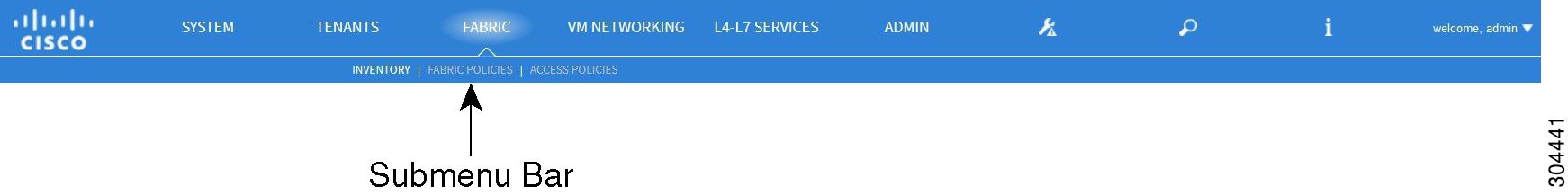
Menu Bar and Submenu Bar
The menu bar and the submenu bar contain the following items:

- SYSTEM Tab
- TENANTS Tab
- FABRIC Tab
- VM NETWORKING Tab
- L4-L7 SERVICES Tab
- ADMIN Tab
- Search Icon
- Navigation Pane
- Work Pane
SYSTEM Tab
Use the System tab to collect and display a summary of the overall system health, its history, and a table of system-level faults.
TENANTS Tab
Use the Tenants tab in the menu bar to perform tenant management. In the submenu bar, you see an Add Tenant link, and a drop-down list that contains all the tenants. Up to five of the most recently used tenants are also displayed on the submenu bar.
-
A tenant contains policies that enable qualified users domain-based access control. Qualified users can access privileges such as tenant administration and networking administration.
-
A user requires read/write privileges for accessing and configuring policies in a domain. A tenant user can have specific privileges into one or more domains.
-
In a multitenancy environment, a tenant provides group user access privileges so that resources are isolated from one another (such as for endpoint groups and networking). These privileges also enable different users to manage different tenants.
FABRIC Tab
-
Inventory tab—Displays the individual components of the fabric.
-
Fabric Policies tab—Displays the monitoring and troubleshooting policies and fabric protocol settings or fabric maximum transmission unit (MTU) settings.
-
Access Policies tab—Displays the access policies that apply to the edge ports of the system. These ports are on the leaf switches that communicate externally.
VM NETWORKING Tab
Use the VM Networking tab to view and configure the inventory of the various virtual machine (VM) managers. You can configure and create various management domains under which connections to individual management systems (such as VMware vCenters or VMware vShield) can be configured. Use the Inventory tab in the submenu bar to view the hypervisors and VMs that are managed by these VM management systems (also referred to as controllers in API).
L4-L7 SERVICES Tab
Use the L4-L7 Services tab to perform services such as importing packages that define Layer 4 to Layer 7 devices. You can view existing service nodes in the Inventory submenu tab.
ADMIN Tab
Use the Admin tab to perform administrative functions such as authentication, authorization, and accounting functions, scheduling policies, retaining and purging records, upgrading firmware, and controlling features such as syslog, Call Home, and SNMP.
Search Icon
Click the Search icon to display the search field. The search field enables you to locate objects by name or other distinctive fields.
Navigation Pane
Use the Navigation pane, which is on the left side of the APIC GUI below the submenu bar, to navigate to all elements of the submenu category. When you select a component in the Navigation pane, the object displays in the Work pane.
Note | If any container in the Navigation pane, for example Application Profiles under a Tenant, contains more than 40 profiles, you cannot click on a profile and expand it in the Navigation pane. You must select the desired profile from the Work pane and expand it. |
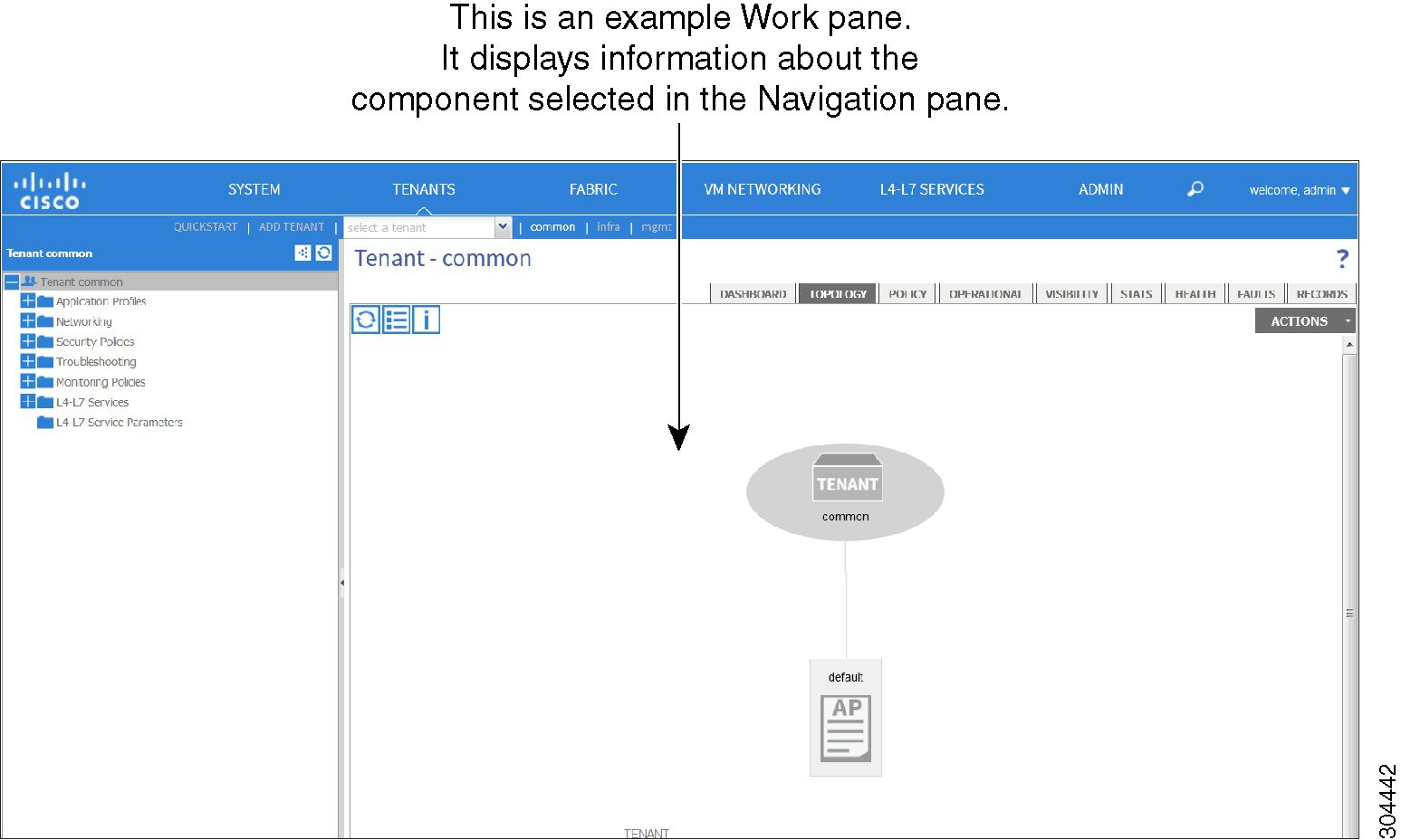
Work Pane
Use the Work pane, which is on the right side of the APIC GUI, to display details about the component that you selected in the Navigation pane. See the following figure for an example view of the Work pane.
The Work pane includes the following elements:
-
A content area that displays tabs. These tabs enable you to access information that is related to the component that you chose in the Navigation pane. The tabs displayed in the content area depend upon the selected component.
-
A link to context-sensitive online help that is represented by a question mark icon in the upper right corner.
GUI Icons
| Icons | Description |
|---|---|
|
|
Control arrow for Navigation pane display |
|
|
Displays online help information |
|
|
Quickstart information |
|
|
Downloads the table as an XML file |
|
|
Displays the table view |
|
|
Displays the table view of the component that you chose in the Navigation pane |
|
|
Refreshes the context of the panel. Click this icon only when there is a connection problem, because the data is updated whenever the repository changes. |
|
|
Settings |
|
|
Next view |
|
|
Previous view |
|
|
Show path |
|
|
Clear path |

Fault, Statistics, and Health Level Icons
| Icons | Description |
|---|---|
|
|
Critical—This icon displays a fault level with critical severity. |
|
|
Major—This icon displays a fault level with major severity. |
|
|
Minor—This icon displays a fault level with minor severity. |
|
|
Warning—This icon displays a fault level that requires a warning. |
API Inspector
Viewing an API Interchange in the GUI
When you perform a task in the APIC graphical user interface (GUI), the GUI creates and sends internal API messages to the operating system to execute the task. By using the API Inspector, which is a built-in tool of the APIC, you can view and copy these API messages. A network administrator can replicate these messages in order to automate key operations, or you can use the messages as examples to develop external applications that will use the API. .
| Step 1 | Log in to the APIC GUI. | ||||||||||||||||||||
| Step 2 | In the upper right corner of the APIC window, click the "welcome, <name>" message to view the drop-down list. | ||||||||||||||||||||
| Step 3 | In the drop-down
list, choose the
Show API
Inspector.
The API Inspector opens in a new browser window. | ||||||||||||||||||||
| Step 4 | In the
Filters toolbar of the
API
Inspector window, choose the types of API log messages to display.
The displayed messages are color-coded according to the selected message types. This table shows the available message types:
| ||||||||||||||||||||
| Step 5 | In the
Search toolbar, you can search the displayed messages
for an exact string or by a regular expression.
This table shows the search controls:
| ||||||||||||||||||||
| Step 6 | In the
Options toolbar, you can arrange the displayed
messages.
This table shows the available options:
|
Example
This example shows two debug messages in the API Inspector window:
13:13:36 DEBUG - method: GET url: http://192.0.20.123/api/class/infraInfra.json
response: {"imdata":[{"infraInfra":{"attributes":{"instanceId":"0:0","childAction":"",
"dn":"uni/infra","lcOwn":"local","name":"","replTs":"never","status":""}}}]}

13:13:40 DEBUG - method: GET url: http://192.0.20.123/api/class/l3extDomP.json?
query-target=subtree&subscription=yes
response: {"subscriptionId":"72057598349672459","imdata":[]}
Initializing the Fabric
About Fabric Initialization
You can build a fabric by adding switches to be managed by the APIC and then validating the steps using the GUI, the CLI, or the API.
Note | Before you can build a fabric, you must have already created an APIC cluster over the out-of-band network. |
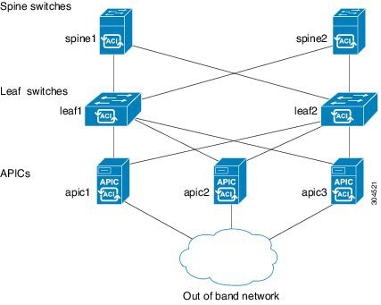
Example Topology
An example topology is as follows:
-
Two spine switches (spine1, spine2)
- Two leaf switches (leaf1, leaf2)
- Three instances of APIC (apic1, apic2, apic3)
The following figure shows an example of a fabric topology.
Example Topology Connections
An example topology with connection details is as follows:
| Name | Connection Details |
|---|---|
|
leaf1 |
eth1/1 = apic1 (eth2/1) eth1/2 = apic2 (eth2/1) eth1/3 = apic3 (eth2/1) eth1/49 = spine1 (eth5/1) eth1/50 = spine2 (eth5/2) |
|
leaf2 |
eth1/1 = apic1 (eth 2/2) eth1/2 = apic2 (eth 2/2) eth1/3 = apic3 (eth 2/2) eth1/49 = spine2 (eth5/1) eth1/50 = spine1 (eth5/2) |
|
spine1 |
eth5/1 = leaf1 (eth1/49) eth5/2 = leaf2 (eth1/50) |
|
spine2 |
eth5/1 = leaf2 (eth1/49) eth5/2 = leaf1 (eth1/50) |
Switch Discovery with the APIC
About Switch Discovery with the APIC
The APIC is a central point of automated provisioning and management for all the switches that are part of the ACI fabric. A single data center might include multiple ACI fabrics; each data center might have its own APIC cluster and Cisco Nexus 9000 Series switches that are part of the fabric. To ensure that a switch is managed only by a single APIC cluster, each switch must be registered with that specific APIC cluster that manages the fabric.
The APIC discovers new switches that are directly connected to any switch it currently manages. Each APIC instance in the cluster first discovers only the leaf switch to which it is directly connected. After the leaf switch is registered with the APIC, the APIC discovers all spine switches that are directly connected to the leaf switch. As each spine switch is registered, that APIC discovers all the leaf switches that are connected to that spine switch. This cascaded discovery allows the APIC to discover the entire fabric topology in a few simple steps.
- Switch Registration with the APIC Cluster
- Switch Discovery Validation and Switch Management from the APIC
- Validating the Fabric Topology
- Unmanaged Switch Connectivity in VM Management
Switch Registration with the APIC Cluster
Note | Before you begin registering a switch, make sure that all switches in the fabric are physically connected and booted in the desired configuration. For information about the installation of the chassis, see http://www.cisco.com/c/en/us/support/cloud-systems-management/application-policy-infrastructure-controller-apic/products-installation-guides-list.html. |
After a switch is registered with the APIC, the switch is part of the APIC-managed fabric inventory. With the Application Centric Infrastructure fabric (ACI fabric), the APIC is the single point of provisioning, management, and monitoring for switches in the infrastructure.
Note | The infrastructure IP address range must not overlap with other IP addresses used in the ACI fabric for in-band and out-of-band networks. |
Registering the Unregistered Switches Using the GUI
Note | The infrastructure IP address range must not overlap with other IP addresses used in the ACI fabric for in-band and out-of-band networks. |
Make sure that all switches in the fabric are physically connected and booted.
| Step 1 | On the menu bar, choose . |
| Step 2 | In the Navigation pane, click Fabric Membership. In the Work pane, in the Fabric Membership table, a single leaf switch is displayed with an ID of 0. It is the leaf switch that is connected to apic1. |
| Step 3 | Configure the
ID by double-clicking the
leaf switch
row, and performing the following actions:
|
| Step 4 | Monitor the Work pane until one or more spine switches appear. |
| Step 5 | Configure the
ID by double-clicking the
spine switch
row, and perform the following actions:
|
| Step 6 | For each switch listed in the Fabric Membership table, perform the following steps: |
Switch Discovery Validation and Switch Management from the APIC
After the switches are registered with the APIC, the APIC performs fabric topology discovery automatically to gain a view of the entire network and to manage all the switches in the fabric topology.
Each switch can be configured, monitored, and upgraded from the APIC without having to access the individual switches.
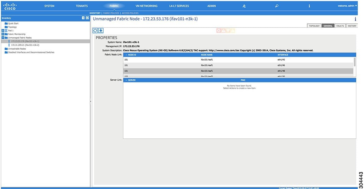
Validating the Registered Switches Using the GUI
Validating the Fabric Topology
After all the switches are registered with the APIC cluster, the APIC automatically discovers all the links and connectivity in the fabric and discovers the entire topology as a result.
Validating the Fabric Topology Using the GUI
| Step 1 | On the menu bar, choose . |
| Step 2 | In the Navigation pane, choose the pod that you want to view. |
| Step 3 | In the Work pane, click the TOPOLOGY tab. The displayed diagram shows all attached switches, APIC instances, and links. |
| Step 4 | (Optional) To view the port-level connectivity of a leaf switch or spine switch, double-click its icon in the topology diagram. To return to the topology diagram, in the upper left corner of the Work pane, click the Previous View icon. |
| Step 5 | (Optional) To refresh the topology diagram, in the upper left corner of the Work pane, click the Refresh icon. |
Unmanaged Switch Connectivity in VM Management
 Feedback