Cisco APIC Layer 4 to Layer 7 Service Graph Deployment Guide, Release 1.2(2g)
Bias-Free Language
The documentation set for this product strives to use bias-free language. For the purposes of this documentation set, bias-free is defined as language that does not imply discrimination based on age, disability, gender, racial identity, ethnic identity, sexual orientation, socioeconomic status, and intersectionality. Exceptions may be present in the documentation due to language that is hardcoded in the user interfaces of the product software, language used based on RFP documentation, or language that is used by a referenced third-party product. Learn more about how Cisco is using Inclusive Language.
- Updated:
- April 20, 2016
Chapter: Deploying a Service Graph
- Overview of Deploying a Service Graph
- About APIC-to-Layer 4 to Layer 7 Device Communication
- About Layer 4 to Layer 7 Configuration Parameters
- Setting Up Management Access to the Layer 4 to Layer 7 Device
- Importing a Device Package Using the GUI
- Creating Bridge Domains and VRFs Using the GUI
- Creating Endpoint Groups and Contracts Using the GUI
- Logical Devices and Concrete Devices
- Function Profiles
- Service Graph Templates
- Creating a Device Selection Policy Using the GUI
Deploying a Service Graph
- Overview of Deploying a Service Graph
- About APIC-to-Layer 4 to Layer 7 Device Communication
- About Layer 4 to Layer 7 Configuration Parameters
- Setting Up Management Access to the Layer 4 to Layer 7 Device
- Importing a Device Package Using the GUI
- Creating Bridge Domains and VRFs Using the GUI
- Creating Endpoint Groups and Contracts Using the GUI
- Logical Devices and Concrete Devices
- Function Profiles
- Service Graph Templates
- Creating a Device Selection Policy Using the GUI
Overview of Deploying a Service Graph
The following list provides an overview of the tasks that you must perform to deploy a service graph:
-
Create physical and virtual domains.
-
Configure the basic management access on the Layer 4 to Layer 7 device
-
Import the device package.
-
Create the bridge domains and VRFs.
-
Create endpoint groups and contracts.
-
Configure logical devices and concrete devices.
-
Create or import a function profile.
See Creating a Function Profile Using the GUI or Importing a Function Profile Using the GUI.
-
Create a service graph template and either use a function profile or enter the Layer 4 to Layer 7 parameters by hand.
See Creating a Layer 4 to Layer 7 Service Graph Template Using the GUI.
-
Apply the service graph template.
See Applying a Service Graph Template to Endpoint Groups Using the GUI.
-
Create the logical device context (optional if you used the GUI wizard).
About APIC-to-Layer 4 to Layer 7 Device Communication
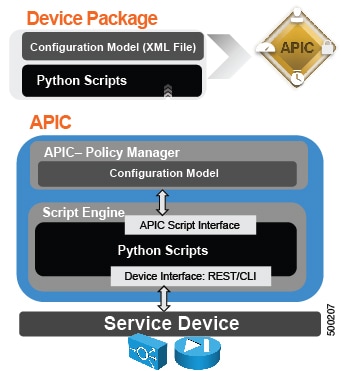
The Application Policy Infrastructure Controller (APIC) requires a device package so that it can communicate with the Layer 4 to Layer 7 device. The device package performs the following functions to enable the communication:
-
Service functions are added to the APIC through device package
-
The device package contains a device model and device scripts (written in Python)
-
The device model defines the service function and configuration
-
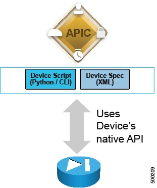
Device scripts translate APIC API callouts to device-specific callouts
-
Device scripts can interface with the device using REST or SSH
The functions in device script are classified into three categories:
-
Device/infrastructure—For device-level configuration and monitoring
-
Service events—For configuring functions, such as a server load balancer or SSL, on the device
-
Endpoint or network events—For handling endpoint and network attach/detach events
APIC uses the device configuration model provided in the package to pass the appropriate configuration to the device scripts. Device script handlers interface with the device using its REST interface or CLI.
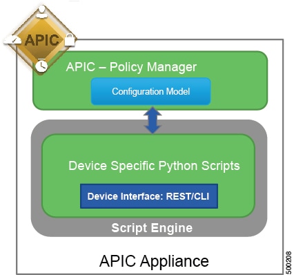
The APIC interfaces with the device by using Python scripts. The APIC calls a device-specific python script function on various events.
The only configuration needed on the Layer 4 to Layer 7 device is management access. You can enable this access by enabling SSH, enabling HTTP access, and configuring the credentials on the device.
About Layer 4 to Layer 7 Configuration Parameters
Each device package defines Layer 4 to Layer 7 configuration parameters, which configure the functions in a service graph. Parameters are always in key and value pairs. The device_specification.xml file within the device package defines the vnsMDevCfg object, which is the model configuration. The vnsMDevCfg object defines the Layer 4 to Layer 7 parameters.
For more information about configuration parameters, see the Cisco APIC Layer 4 to Layer 7 Services Deployment Guide .
You can use a function profile so that you can reuse the same parameter values when deploying a service graph. For more information, see About Function Profiles.
Setting Up Management Access to the Layer 4 to Layer 7 Device
The service graph configuration requires the Application Policy Infrastructure Controller (APIC) to communicate with the Layer 4 to Layer 7 device management address. For a physical appliance, the APIC communicates with the IP address of the management port of the appliance. In the case of a virtual appliance, the APIC communicates with the management address of the virtual appliance that is associated with the first vNIC (network adapter 1).
For out-of-band management, no particular configuration is needed on the APIC to establish this communication.
For in-band management, the APIC can talk to a physical or virtual appliance connected to the fabric through the Cisco Application Centric Infrastructure (ACI) fabric itself. You can configure a management endpoint group and create a pool of addresses that are used to apply Network Address Translation (NAT) to the IP address of the APIC to communicate with the appliance. You implement this capability by creating an endpoint group for management and a management address pool in this endpoint group.
The APIC is a clustered set of servers, each with its own IP address. You can configure the service graph from any of the controllers, and the configurations and the device package are replicated. Only one controller will talk to the Layer 4 to Layer 7 device to configure it, and you do not need to know which one it is except for troubleshooting purposes.
Importing a Device Package Using the GUI
Before performing any configuration based on service graphs, you must download and install the appropriate device package in the Application Policy Infrastructure Controller (APIC) . A device package specifies to the APIC what devices you have and what the devices can do.
| Step 1 | Download an
appropriate device package. You can find the list of partners at the following
URL:
http://www.cisco.com/c/en/us/solutions/data-center-virtualization/ecosystem.html This URL is the Partner Ecosystem page, where you can download the appropriate device package. |
| Step 2 | Log in to the APIC as the provider administrator. |
| Step 3 | On the menu bar, choose . |
| Step 4 | In the Navigation pane, choose L4-L7 Service Device Types. |
| Step 5 | In the Work pane, choose . The Import Device Package dialog box appears. |
| Step 6 | Click
Browse... and browse to the device package that you
want to use.
For information about creating device packages, see the Cisco APIC Layer 4 to Layer 7 Device Package Development Guide. |
| Step 7 | Click Open. |
| Step 8 | Click Submit. |
Creating Bridge Domains and VRFs Using the GUI
The data plane connectivity of the Layer 4 to Layer 7 devices is based on bridge domains. You need to create at least two bridge domains: one for the client side (or outside or consumer side) and one for the server side (inside or provider side).
Creating Endpoint Groups and Contracts Using the GUI
The service graph requires a contract and subject to be associated with it. The service graph is deployed between a client-side, outside, consumer endpoint group and a server-side, inside, provider endpoint group. The first endpoint group is associated with the client-side or outside bridge domain and the second endpoint group is associated with the server-side or inside bridge domain.
Logical Devices and Concrete Devices
Cisco Application Centric Infrastructure (ACI) uses the following terminology:
-
Concrete device—A concrete, or physical, device is a service device, such as a single load balancer or a single firewall.
-
Logical device—A logical device is a cluster of two devices that operate in active-standby mode.
-
Logical device context—The logical device context specifies the criteria for determining which specific device in the inventory to use to render a service graph.
Firewalls and load balancers are seldom deployed as single devices. Instead, they normally are deployed as clusters of active-standby pairs. Cisco ACI provides an abstraction to represent these clusters: the device cluster or logical device. The administrator must help ACI perform the mapping between the service graph and the clusters of firewalls and load balancers. The administrator also needs to tell ACI which pairs of concrete devices constitute a cluster. The GUI simplifies this process, guiding you through the steps to define each cluster of firewalls or load balancers.
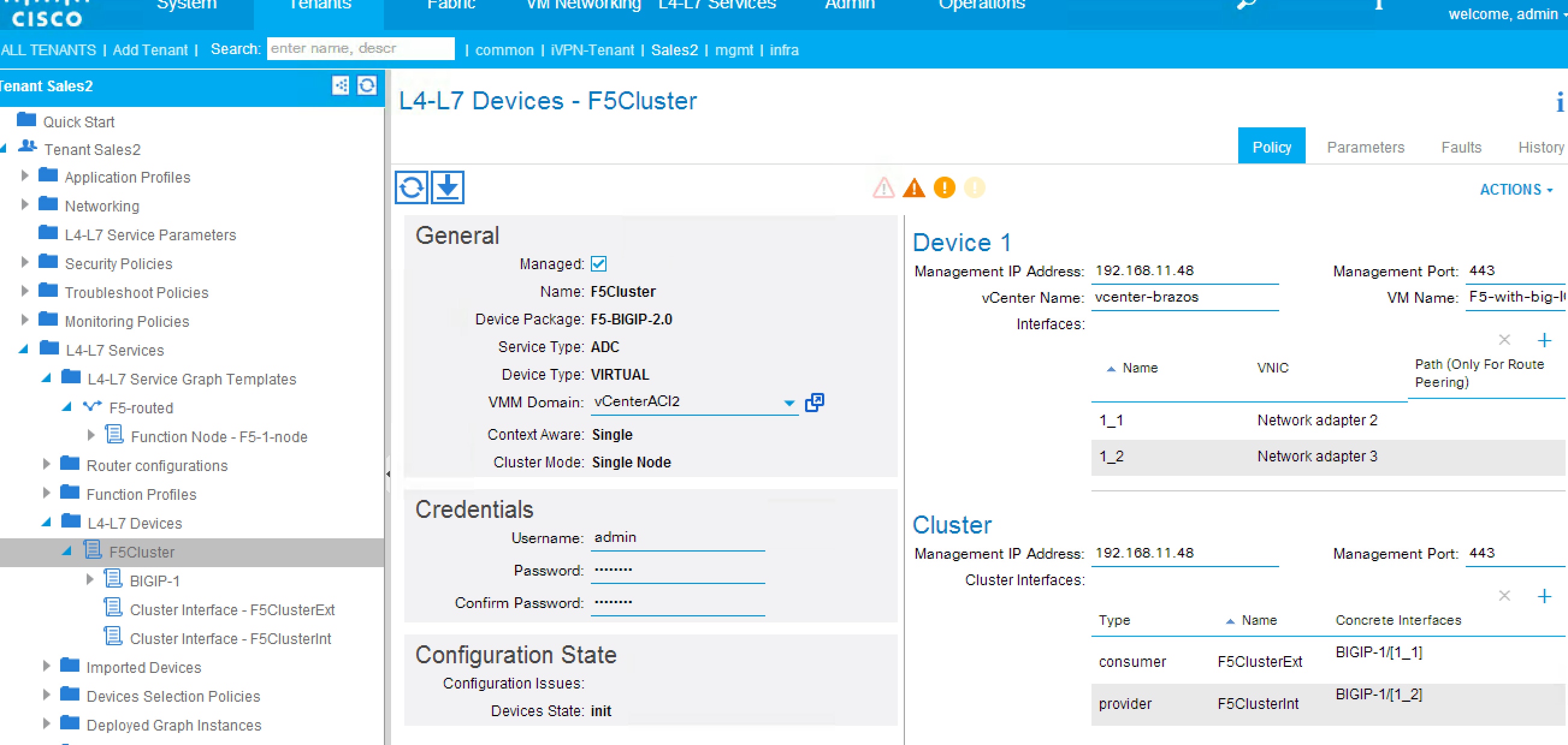
The following screenshot shows the configuration dialog box for concrete and logical devices:
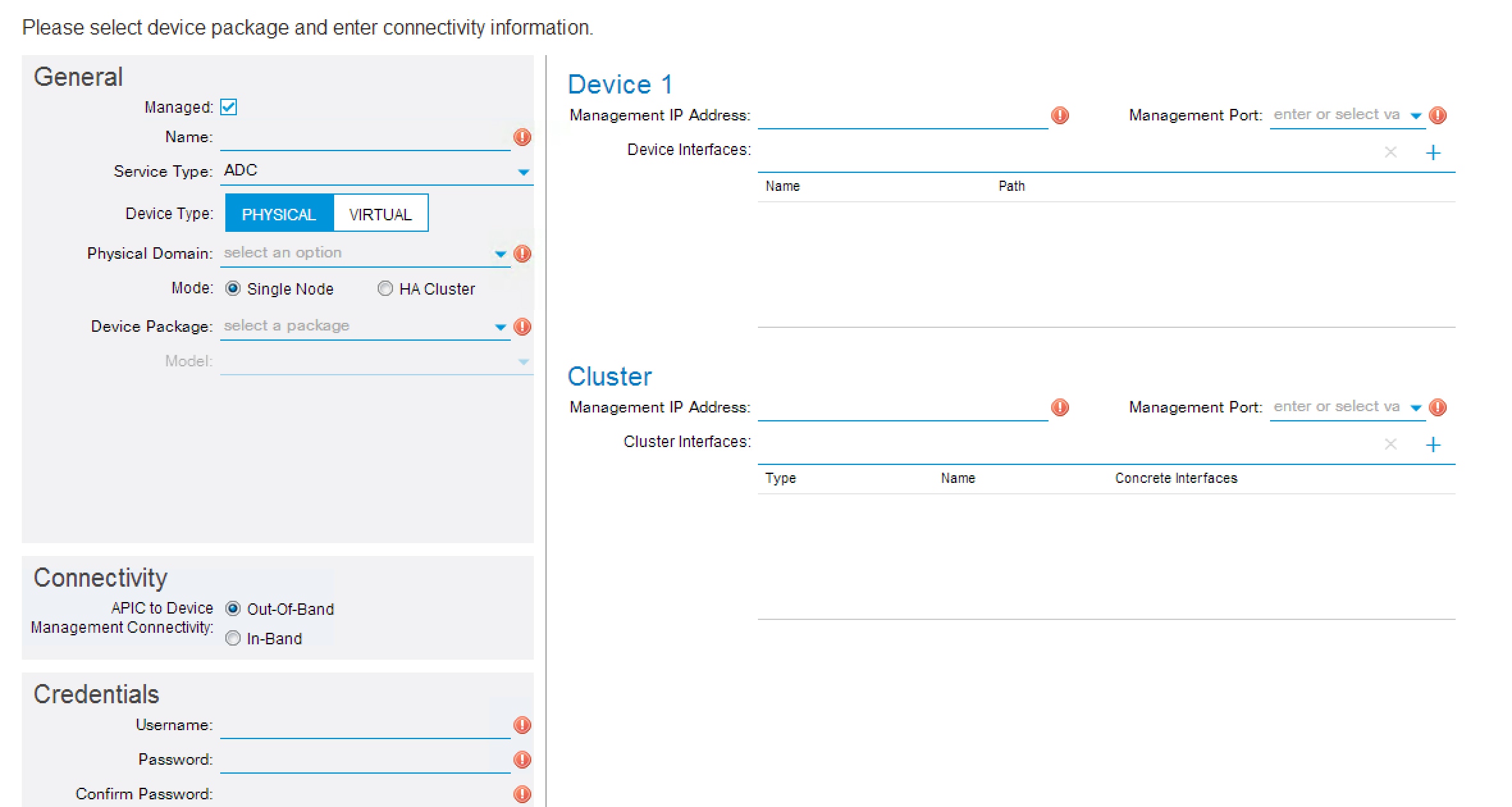
The fields in this dialog box refer to the management information for the cluster of devices. The virtual address is the management address used when the pair of firewalls or load balancers is operating in active-standby mode.
- About Model Choice
- About Connectivity Options
- About Interface Numbering
- Creating a Logical or Concrete Device Using the GUI
- Creating a Logical or Concrete Device with an HA Cluster Using the GUI
- Verifying the Status of a Logical or Concrete Device
About Model Choice
When you create a concrete device (CDev), you can choose the model for a given device package, matching the model to the type of device that you are configuring. In some cases, you might want to choose the option Unknown, which is the generic model type. With this option, you have more control over the definition of the type of device and whether or not the device is context aware.
About Connectivity Options
Under the concrete device definition, you must specify which domain to use. This setting allows Cisco Application Centric Infrastructure (ACI) to locate the device if it is on a virtualized server and provides a pool of VLANs that ACI can use to create the connectivity. Another option available as part of the concrete device configuration is EPG. This option appears only if you are configuring in-band management and if this is the endpoint group that provides management access to the virtual appliance. In this case, vNIC1 on the virtual appliance is connected to this endpoint group.
About Interface Numbering
When using the GUI, you must configure logical interfaces. A logical interface defines a naming convention for the building block of the cluster and its mapping to the concrete device and to the metadevice.
For example, the metadevice of an F5 load balancer defines an external and an internal interface. The cluster model in Cisco Application Centric Infrastructure (ACI) defines two interfaces and lets you choose the name (logical interface, or Lif). Each interface maps to a metadevice interface and also to a physical (concrete) device interface. This process allows ACI to render the graph correctly.
The following screenshot shows an example of a mapping of a logical interface to a concrete device interface:
The interfaces have different names on the service device itself than the names that they have as part of the ACI configuration. For example, in the case of F5, the interfaces are numbered 1.1, 1.2, and so on. ACI allows you to reference these interfaces using the character "_" as a replacement for the "/" and "." characters. For example, F5 interfaces are referred to as 1_1, 1_2, and so on.
Creating a Logical or Concrete Device Using the GUI
You can use a virtual or a physical Layer 4 to Layer 7 device in a service graph. You configure a concrete device to provide information to the Application Policy Infrastructure Controller (APIC) about where the device is and how to manage it. You configure a logical device to provide information to the APIC about the HA pair of Layer 4 to Layer 7 devices that Cisco Application Centric Infrastructure (ACI) can use for service graph purposes.
When you connecting to a physical device, you specify the physical interface. When you connect to a virtual machine, you specify the VMM domain, the virtual machine, and the virtual interfaces.
When defining a logical or concrete device, ACI gives you the option to choose which type of device it is by using the information included in the device package. Additionally, you can select an unknown model.
Creating a Logical or Concrete Device with an HA Cluster Using the GUI
An HA configuration is set up at two levels: the logical device level, and the Layer 4 to Layer 7 parameters level.
At the logical device level, you tell Cisco Application Centric Infrastructure (ACI) which interfaces are the same interface. For example, the outside is made of 2 outside interfaces of each appliance. You also indicate which ports are failover link ports.
At the Layer 4 to Layer 7 parameters level, you provide the IP address for each interface. You might need to make some IP addresses "floating". You also provide the IP address for the failover links. For a physical ASA HA configuration, the IP address for the cluster interface is the admin context IP address.
Verifying the Status of a Logical or Concrete Device
You can verify the status of the device appliance by viewing the logical or concrete device configuration to see if it is stable.
Function Profiles
About Function Profiles
A function profile is a collection of pre-configured Layer 4 to Layer 7 parameters. Entering the Layer 4 to Layer 7 parameters is tedious and error prone due to the often large number of parameters that must be entered manually and individually. The function profile solves this problem since it is reusable. A function profile is specific to one node or function used in the template. The function profile is like an XML DTD with a reduced set of fields or with fields that are pre-populated based on the specific use case.
For example, a function profile for a web service could have the following preset parameters:
Whenever you use this function profile, these parameters will automatically be set. You can then add more parameters or edit the preset parameters as necessary.
When you apply a service graph template, you can choose a function profile to deploy with the template. Function profiles can be also already part of the device package, in which case you only need to edit the function profiles to complete them when you deploy the service graph template.
When you create a function profile, some of the parameters are mandatory. Most of the mandatory parameters are highlighted in red in the GUI, but you must refer to the vendor's device package documentation to verify which parameters are mandatory.
Creating a Function Profile Using the GUI
A Function Profile provides the default values for your service graph template. The following procedure explains how to create a new function profile.
Importing a Function Profile Using the GUI
If you already have a function profile that you saved to your local machine, you can import it into (post it to) the Application Policy Infrastructure Controller (APIC).
| Step 1 | On the menu bar, choose . |
| Step 2 | In the Work pane, double click the tenant's name. |
| Step 3 | In the
Navigation pane, choose
.
function_profile_group_name is the function profile group into which you want to import the function profile. |
| Step 4 | Right click function_profile_group_name and choose Post .... |
| Step 5 | In the Post dialog box, click Browse... and browse to the function profile's XML or JSON file. |
| Step 6 | Click Post. |
| Step 7 | (Optional)Modify or add to the parameters in the imported function profile. |
Service Graph Templates
Creating a Layer 4 to Layer 7 Service Graph Template Using the GUI
A service graph template is a sequence of Layer 4 to Layer 7 functions or devices and their associated configuration, which can be provided by using function profiles. The service graph template must be associated with a contract to be "rendered"—or configured—on the Layer 4 to Layer 7 device and on the fabric.
| Step 1 | On the menu bar, choose . | ||||||||
| Step 2 | In the Work pane, double click the tenant's name. | ||||||||
| Step 3 | In the Navigation pane, choose . | ||||||||
| Step 4 | In the Work pane, choose . | ||||||||
| Step 5 | In the Create a L4-L7 Service Graph Template dialog box, in the Device Clusters section, choose a device cluster. | ||||||||
| Step 6 | Complete the
following fields:
| ||||||||
| Step 7 | (Only for creating a new service graph template) Drag a device from the Device Clusters section and drop it between the consumer endpoint group and provider endpoint group to create a service node. | ||||||||
| Step 8 | (Optional)(Only for cloning an existing service graph template) Remove the existing node and drag a different device cluster to the node area to create a service node. | ||||||||
| Step 9 | Click Submit. | ||||||||
| Step 10 | (Optional)In the Navigation pane. click the service graph template. The screen presents a graphic topology of the service graph template. |
Applying a Service Graph Template to Endpoint Groups Using the GUI
The following procedure explains how to apply a service graph template to endpoint groups:
You must have created the following things:
| Step 1 | On the menu bar, choose . | ||||||||||||||
| Step 2 | In the Work pane, double click the tenant's name. | ||||||||||||||
| Step 3 | In the Navigation pane, choose . | ||||||||||||||
| Step 4 | In the Work
pane, choose
.
You will be associating a Layer 4 to Layer 7 service graph template to your consumer and provider endpoint groups. | ||||||||||||||
| Step 5 | In the
Apply
L4-L7 Service Graph Template To EPGs dialog, in the
EPG
Information section, complete the following fields:
| ||||||||||||||
| Step 6 | In the
Contract Information section, complete the following
fields:
| ||||||||||||||
| Step 7 | Click Next. | ||||||||||||||
| Step 8 | In the Device Clusters section, choose a device cluster. | ||||||||||||||
| Step 9 | Complete the
following field:
| ||||||||||||||
| Step 10 | (Optional) Remove the existing node and drag a different device cluster to the node area to create a service node. | ||||||||||||||
| Step 11 | In the
unmanaged information section, complete the following
field:
| ||||||||||||||
| Step 12 | (Only for managed devices) Click Next. | ||||||||||||||
| Step 13 | (Only for managed devices) In the Parameters screen, in the Required Parameters tab, enter the names and values, as appropriate, for all of the required parameters. | ||||||||||||||
| Step 14 | Click Finish. You now have an active service graph template. The APIC populates the Layer 4 to Layer 7 parameters based on the chosen function profile and colors the mandatory parameters in green if they are configured correctly. |
Verifying a Service Graph Deployment Using the GUI
After you apply a service graph template, the service graph is associated with a contract and you can see the list of deployed graphs and rendered concrete devices in the Layer 4 to Layer 7 devices portion of the GUI. When the graph is rendered, you will see configurations appear in the device that is part of the graph. The following procedure verifies that the service graph deployed successfully.
| Step 1 | On the menu bar, choose . |
| Step 2 | In the Work pane, double click the tenant's name. |
| Step 3 | In the Navigation pane, choose . |
| Step 4 | In the Work pane, look for the device in the table. If the service graph deployment failed, you will not see the device. |
| Step 5 | In the
Navigation pane, choose
.
The following screenshot shows an example of deployed (rendered) service graphs: 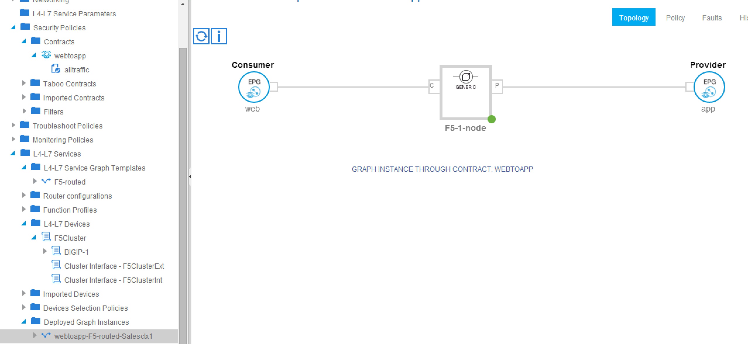 If the service graph has been deployed, the graph is listed in the Deployed Graph Instances folder. |
| Step 6 | In the
Navigation pane, choose
to see
which VLANs and which port groups have been allocated by
Cisco Application Centric
Infrastructure
(ACI)
to establish the connectivity with the service device.
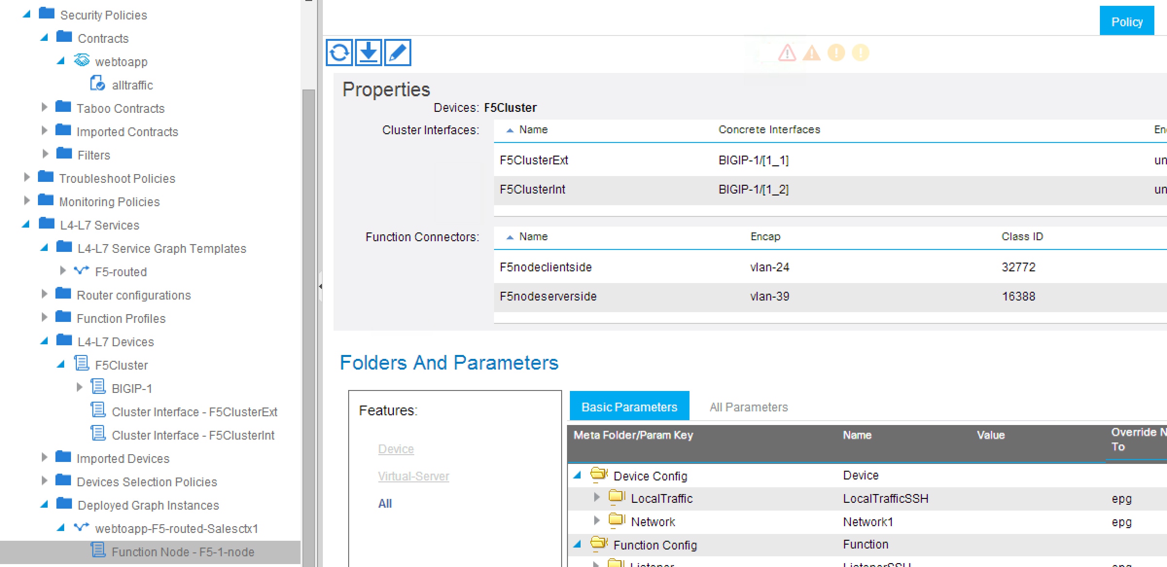 In the case of virtual appliances, ACI creates some port groups called shadow endpoint groups, and ACI moves the vNIC of the appliance to these port groups. |
Undoing a Service Graph Configuration Using the GUI
Creating a Device Selection Policy Using the GUI
If you did not use the Apply L4-L7 Service Graph Template To EPGs wizard to apply the service graph template, you might need to configure a device selection policy (also known as a logical device context). The device selection policy instructs Cisco Application Centric Infrastructure (ACI) about which firewall or load balancer device to use to render a graph.
If you used the Apply L4-L7 Service Graph Template To EPGs wizard to apply the service graph template, then a device selection policy was configured automatically and you do not need to configure one manually.
 Note | When using the NX-OS-style CLI, the device selection policy is configured automatically; there are no equivalent NX-OS-style CLI commands. |
| Step 1 | On the menu bar, choose . |
| Step 2 | In the Work pane, double click the tenant's name. |
| Step 3 | In the Navigation pane, choose . |
| Step 4 | In the Work pane, choose . |
| Step 5 | In the
Create
Logical Device Context dialog box, fill in the fields as required,
except as specified below:
|
| Step 6 | In the
Cluster Interface Contexts section, click
+ to add a cluster interface context.
|
| Step 7 | Click Submit. |
 Feedback