Cisco APIC Layer 4 to Layer 7 Service Graph Deployment Guide, Release 1.2(2g)
Bias-Free Language
The documentation set for this product strives to use bias-free language. For the purposes of this documentation set, bias-free is defined as language that does not imply discrimination based on age, disability, gender, racial identity, ethnic identity, sexual orientation, socioeconomic status, and intersectionality. Exceptions may be present in the documentation due to language that is hardcoded in the user interfaces of the product software, language used based on RFP documentation, or language that is used by a referenced third-party product. Learn more about how Cisco is using Inclusive Language.
- Updated:
- April 20, 2016
Chapter: Deploying F5
- About the F5 Operational Model
- Translation of F5 Terminology
- About F5 Partitions
- F5 in GoTo Mode
- About Deploying F5 in GoTo Mode
- Overview of Preparing an F5 Device in GoTo Mode
- Configuring Bridge Domains for F5 in GoTo Mode
- Adding Endpoint Attach Support for F5 in GoTo Mode
- Tuning the Server-Side Bridge Domain for Flood Removal for F5 in GoTo Mode
- F5 GoTo Mode Design Examples
- Deploying F5 in GoTo Mode
- F5 in One-Arm Mode
- Verifying the Configuration for an F5 Device
- Undoing a Service Graph Configuration for F5
Deploying F5
- About the F5 Operational Model
- Translation of F5 Terminology
- About F5 Partitions
- F5 in GoTo Mode
- F5 in One-Arm Mode
- Verifying the Configuration for an F5 Device
- Undoing a Service Graph Configuration for F5
About the F5 Operational Model
There are two main operational models that you can use with F5. In the first model, which is the default mode, the F5 configuration is managed through the Application Policy Infrastructure Controller (APIC). In the second model, the F5 administrator uses Big-IQ to define the Layer 4 to Layer 7 service configurations and the APIC administrator just associates them with the service graph. This document covers only the first deployment model.
The default operational model when using F5 with the APIC requires that all changes made to the F5 device are performed through the APIC. The following figure illustrates that the configuration of the F5 device is managed by the APIC:
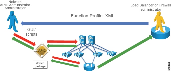
The F5 administrator provides the XML or JSON function profile configuration to the APIC administrator who then pushes the function profile through the APIC to the F5 device.
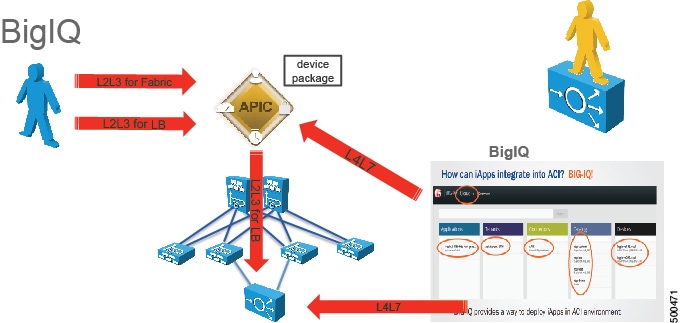
The following figure illustrates the management model whereby the F5 administrator defines iApps on Big-IQ, and the Layer 4 to Layer 7 parameters are passed to the APIC to be instantiated of the F5 appliance:
Translation of F5 Terminology
The following table translates F5 terminology into Cisco load balancer terminology:
|
F5 Terminology |
Cisco Load Balancer Terminology |
|---|---|
|
Listener IP |
Virtual IP |
|
Pool |
Serverfarm |
|
Pool Member |
Real Server |
|
SelfIP Address |
Interface Address (alias in content switching module terminology) |
|
Floating yes/no |
Makes the SelfIP floating, such as HSRP or VRRP |
|
Route Domain |
VRF, normally one route domain per partition on F5 |
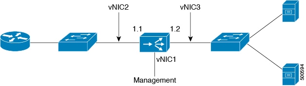
The following table translates which vNIC corresponds to which interface in F5 and Cisco Application Centric Infrastructure (ACI):
|
Interface |
VMware |
F5 |
ACI |
IP address is entered as |
|---|---|---|---|---|
|
Management |
vNIC1 |
Management |
N/A |
N/A |
|
Outside |
vNIC2 |
1.1 |
1_1 |
ExternalSelfIP |
|
Inside |
vNIC3 |
1.2 |
1_2 |
InternalSelfIP |
The following figure illustrates the naming convention for the interfaces in the case of an F5 load balancer:
About F5 Partitions
When you define the Layer 4 to Layer 7 device as multicontext, you can put the device into a tenant such as tenant Common and then export the device to multiple tenants. Multicontext support requires a physical appliance. The virtual appliance also supports multicontext in the sense that you can create multiple partitions, but a virtual appliance will not forward the traffic. Since the virtual appliance is on multiple tenants, the vNICs cannot be shared because there cannot be a trunk with VLANs on the same vNIC.
Application Policy Infrastructure Controller (APIC) uses tenant Common for objects that can be used by other tenants. For example, APIC has filters in the common partition that can be used from other tenants. F5 has a "common" partition that functions similar to tenant Common. The common partition has configurations to manage the F5 device. The configurations can be exported to other partitions, such as the "monitor" configurations, which correspond to "probes" or "keepalive" in Cisco load balancer terminology. APIC logs into the common partition, but creates a new F5 partition for each tenant.
You can have multiple virtual servers for different applications in the same BIG-IP partition or APIC tenant. A partition created by APIC inside BIG-IP is prefixed by "apic_", followed by the tenant ID to represent the partition in F5. For example, "apic_5437". The tenant ID is based on the service graph virtual device (VDev) ID. Each partition is assigned an individual route domain for Layer 3 separation. A virtual server created by APIC inside BIG-IP is prefixed by "apic_tenant-ID", followed by the service graph ID. For example, " apic_5437_3456".
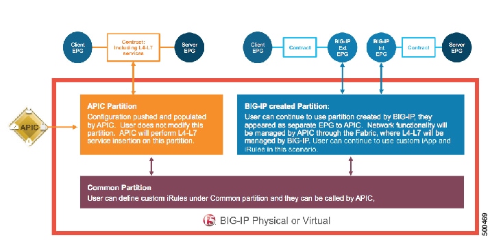
When the APIC manages an F5 partition, the F5 administrator cannot make changes to that partition directly from the F5 interface. All changes must be performed exclusively using the APIC. A single F5 device can have partitions that are managed by the APIC and other partitions that are managed by the F5 administrator directly. This design approach is called "mixed mode". The following figure illustrates this concept:
F5 in GoTo Mode
About Deploying F5 in GoTo Mode
The following figure illustrates the topology for deploying Cisco Application Centric Infrastructure (ACI) fabric with F5 devices:
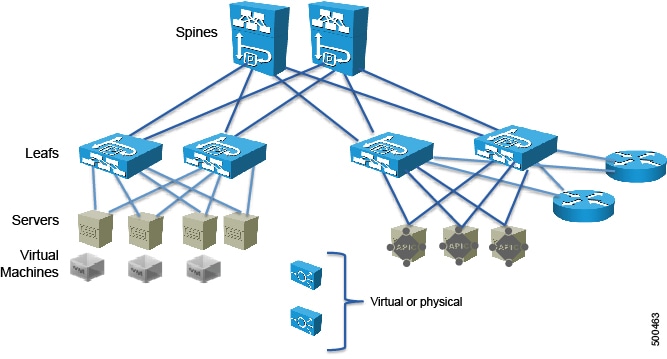
The F5 load balancer can be connected as a physical or virtual device to any of the leafs in the topology.
The following figure illustrates the logical topology for an F5 GoTo deployment:
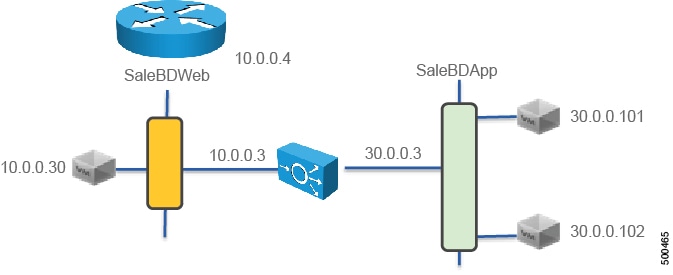
The F5 device is deployed as part of a contract connecting the EPG SaleBDWeb and SaleBDApp which in the picture are on subnets 10.0.0.x and 30.0.0.x respectively
To deploy an F5 device in the GoTo mode, you must perform the following steps:
-
Configure 2 bridge domains
-
Configure 2 endpoint groups, with each one associated with a different bridge domain
-
Configure the F5 device as a GoTo device
-
Configure a VIP on the same subnet as the bridge domain that the F5 connects to on the client side (outside, or consumer side)
-
Configure the contract between the outside and inside endpoint group (or server side or provider side)
-
Associate the service graph with the contract
You must configure a different service graph instance for each virtual IP address.
-
Associate the external logical interface with 1_1 (which in the case of F5 VE is Network Adapter 2)
-
Associate the internal logical interface with 1_2 (which in the case of F5 VE is Network Adapter 3)
Overview of Preparing an F5 Device in GoTo Mode
The following procedure provides an overview of preparing an F5 device to be deployed in GoTo mode.
Configuring Bridge Domains for F5 in GoTo Mode
When you configure the bridge domains for F5 in GoTo mode, configure the bridge domains as you would for a generic configuration, except as follows:
-
L2 Unknown Unicast radio buttons—Choose Flood.
-
ARP Flooding check box—Put a check in the check box.
-
Unicast Routing check box—This configuration depends on whether this is the outside bridge domain and whether you need the Cisco Application Centric Infrastructure (ACI) fabric to route. If you do not know, leave this check box unchecked.
For information on how to configure bridge domains, see Creating Bridge Domains and VRFs Using the GUI.
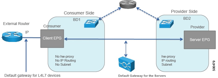
The following figure illustrates a GoTo mode deployment without hardware-proxy and without endpoint attach:
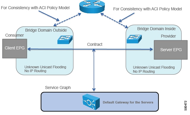
If you need the mapping database to learn the endpoints' IP addresses, you must enable unicast routing in the bridge domains.
Adding Endpoint Attach Support for F5 in GoTo Mode
You can deploy an F5 device in a service graph in a way that the endpoints that are discovered in the provider endpoint group are automatically added to the pool of load balanced servers. In the F5 device, this feature is called "endpoint attach".

The following procedure enables endpoint attach.
The configuration in XML format is as follows:
<vnsAbsNode funcType="GoTo" name="F5-1-node" shareEncap="no" managed="yes">
<!-- This is specifies which function this is -->
    <vnsRsNodeToMFunc tDn="uni/infra/mDev-F5-BIGIP-2.0/mFunc-Virtual-Server"/>
    …

<!-- This is the name of the connectivity point of the node -->
<!-- the name is referenced by "AbsNode-F5-1-node/AbsFConn-F5nodeserverside" -->
<!-- Attachment Notify is used to create a Pool of servers dynamically on the load balancer -->
    <vnsAbsFuncConn attNotify="yes" name="F5nodeserverside" >
<!-- This is the Metadevice information i.e. the mConnector -->
<!-- "internal" is not an arbitrary name, it is the definition of the type of interface -->
<!-- and it has a precise meaning in the meta device -->
    <vnsRsMConnAtt tDn="uni/infra/mDev-F5-BIGIP-2.0/mFunc-Virtual-Server/mConn-internal"/>
</vnsAbsFuncConn>
With these configurations in place, you can define the Layer 4 to Layer 7 parameters for the load balancer that refer to these endpoints. This is achieved in the Layer 4 to Layer 7 parameters as follows:
<vnsFolderInst  ctrctNameOrLbl="webtoapp" graphNameOrLbl="F5-routed" key="Pool" locked="no" name="ServerPoolSSH" nodeNameOrLbl="F5-1-node">
<!-- CONFIGURE LOAD BALANCING TYPE HERE -->
    <vnsParamInst  key="LBMethod" locked="no"  name="LBMethod"  value="ROUND_ROBIN"/>
<!-- Use Dynamic only if you want to use the EPG endpoints to autopopulate the serverfarm pool -->
    <vnsParamInst key="PoolType" name="PoolType" value="DYNAMIC"/>
Tuning the Server-Side Bridge Domain for Flood Removal for F5 in GoTo Mode
On the server-side bridge domain, it can be beneficial to reduce flooding for unknown unicast packets. To do this, you can enable hardware proxy on the bridge domain. You should keep ARP flooding enabled because it might be necessary in the presence of F5 deployed in HA pairs.
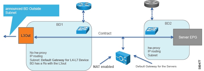
F5 GoTo Mode Design Examples
The following figures illustrate F5 GoTo mode deployments with various scenarios: some with the client connected directly to the fabric, some with the fabric providing routing to the outside, and some with an external router. The figures include the recommended bridge domain settings for both client and server-side bridge domains.
The settings for the server-side or provider-side (also known as the internal bridge domain, BD2) include IP routing in case you decide to use the endpoint attach feature. If you do not want to use endpoint attach and you do not care about flood reduction in the server-side bridge domain, you can configure the bridge domain without IP routing.

Deploying F5 in GoTo Mode
The tasks that you must perform to deploy F5 in GoTo mode are nearly identical to the tasks for generically deploying a service graph, with a few differences. The following procedure provides the generic service graph deployment tasks, along with information about what you must do differently to deploy F5 in GoTo mode.
| Step 1 | Import the device package. |
| Step 2 | Create the bridge domains
and VRFs.
See Creating Bridge Domains and VRFs Using the GUI.
|
| Step 3 | Create endpoint groups and contracts. |
| Step 4 | Configure logical devices
and concrete devices.
See Creating a Logical or Concrete Device Using the GUI.
|
| Step 5 | Create or import a function
profile.
See Creating a Function Profile Using the GUI or Importing a Function Profile Using the GUI.
The following table describes the mandatory Layer 4 to Layer 7 parameters and provides examples of possible values that you must change for your specific configuration: The following XML is an example of a Layer 4 to Layer 7 parameters configuration: <!-- Note: some parameters are mandatory: -->
<!-- such as the Listener, the Pool, the Monitor, the virtual address, the load balancing method -->
<!-- without them the graph is not deployed -->
<!-- NETWORK FOLDER (called here Network1): SELFIP, STATIC ROUTE, NAT POOL -->
<!-- IP addresses for the F5 interfaces and default route we are just using the external interface here -->
<!-- The IP of the external inteface must be on the same subnet as the BD that connects to the VRF -->
<vnsFolderInst ctrctNameOrLbl="webtoapp" graphNameOrLbl="F5-GoTo" key="Network" locked="no" name="Network1" nodeNameOrLbl="F5-1-node" scopedBy="epg">
<vnsFolderInst ctrctNameOrLbl="webtoapp" graphNameOrLbl="F5-GoTo" key="ExternalSelfIP" locked="no" name="ExternalSelfIP" nodeNameOrLbl="F5-1-node">
<vnsParamInst key="Floating" locked="no" name="Floating" value="NO"/>
<vnsParamInst key="SelfIPNetmask" locked="no" name="SelfIPNetmask" value="255.255.255.0"/>
<vnsParamInst key="SelfIPAddress" locked="no" name="SelfIPAddress" value="10.0.0.3"/>
<vnsParamInst key="PortLockdown" locked="no" name="PortLockdown" value="DEFAULT"/>
</vnsFolderInst>
<vnsFolderInst ctrctNameOrLbl="webtoapp" graphNameOrLbl="F5-GoTo" key="InternalSelfIP" locked="no" name="InternalSelfIP" nodeNameOrLbl="F5-1-node">
<vnsParamInst key="Floating" locked="no" name="Floating" value="NO"/>
<vnsParamInst key="SelfIPNetmask" locked="no" name="SelfIPNetmask" value="255.255.255.0"/>
<vnsParamInst key="SelfIPAddress" locked="no" name="SelfIPAddress" value="30.0.0.3"/>
<vnsParamInst key="PortLockdown" locked="no" name="PortLockdown" value="DEFAULT"/>
</vnsFolderInst>
<!-- STATIC ROUTE -->
<vnsFolderInst ctrctNameOrLbl="webtoapp" graphNameOrLbl="F5-GoTo" key="Route" locked="no" name="Route" nodeNameOrLbl="F5-1-node">
<vnsParamInst key="DestinationIPAddress" locked="no" name="DestinationIPAddress" value="0.0.0.0"/>
<vnsParamInst key="DestinationNetmask" locked="no" name="DestinationNetmask" value="0.0.0.0"/>
<vnsParamInst key="NextHopIPAddress" locked="no" name="NextHopIPAddress" value="10.0.0.2"/>
</vnsFolderInst>
</vnsFolderInst>
<!-- END OF NETWORK FOLDER CONFIGURATION -->
<!-- LOCAL TRAFFIC FOLDER, called here LocalTrafficSSH -->
<!-- Definition of the load balancing mechanism, serverfarm and of monitoring-->
<vnsFolderInst ctrctNameOrLbl="webtoapp" graphNameOrLbl="F5-GoTo" key="LocalTraffic" locked="no" name="LocalTrafficSSH" nodeNameOrLbl="F5-1-node">
<!-- CONFIGURE HERE SERVER MONITORING called here "ICMPMonitor"-->
<vnsFolderInst ctrctNameOrLbl="webtoapp" graphNameOrLbl="F5-GoTo" key="Monitor" locked="no" name="ICMPMonitor" nodeNameOrLbl="F5-1-node">
<vnsParamInst key="Type" locked="no" name="ICMP" value="ICMP"/>
<vnsParamInst key="FailByAttempts" locked="no" name="FailByAttempts" value="3"/>
<vnsParamInst key="FrequencySeconds" locked="no" name="FrequencySeconds" value="5"/>
</vnsFolderInst>
<!-- CONFIGURE HERE THE LIST OF SERVERS called here "ServerPoolSSH"-->
<vnsFolderInst ctrctNameOrLbl="webtoapp" graphNameOrLbl="F5-GoTo" key="Pool" locked="no" name="ServerPoolSSH" nodeNameOrLbl="F5-1-node">
<!-- CONFIGURE HERE LOAD BALANCING TYPE -->
<vnsParamInst key="LBMethod" locked="no" name="LBMethod" value="ROUND_ROBIN"/>
<!-- Use Dynamic only if you want to use the EPG endpoints to autopopulate the serverfarm pool -->
<vnsParamInst key="PoolType" name="PoolType" value="DYNAMIC"/>
<!-- Uncomment this section if you want to use statically defined pool members -->
<!-- vnsParamInst key="PoolType" locked="no" name="PoolType" value="STATIC"/>
<!-- First Server in the Pool: Member1 -->
<!-- vnsFolderInst ctrctNameOrLbl="webtoapp" graphNameOrLbl="F5-GoTo" key="Member" locked="no" name="Member1" nodeNameOrLbl="F5-1-node"-->
<!-- vnsParamInst key="Port" name="Port" value="22"/-->
<!--vnsParamInst key="IPAddress" name="IPAddress" value="30.0.0.101"/-->
<!-- /vnsFolderInst -->
<!-- Second Server in the Pool: Member2 -->
<!--vnsFolderInst ctrctNameOrLbl="webtoapp" graphNameOrLbl="F5-GoTo" key="Member" locked="no" name="Member2" nodeNameOrLbl="F5-1-node"-->
<!--vnsParamInst key="Port" name="Port" value="22"/-->
<!--vnsParamInst key="IPAddress" name="IPAddress" value="30.0.0.102"/-->
<!--/vnsFolderInst>
<!-- This is a relation to the Pool Monitoring defined in "Monitor" -->
<vnsFolderInst ctrctNameOrLbl="webtoapp" graphNameOrLbl="F5-GoTo" key="PoolMonitor" locked="no" name="ArbitraryNamePoolMonitor" nodeNameOrLbl="F5-1-node">
<vnsCfgRelInst key="PoolMonitorRel" locked="no" name="PoolMonitorRel" targetName="LocalTrafficSSH/ICMPMonitor"/>
</vnsFolderInst>
</vnsFolderInst>
</vnsFolderInst>
<!-- END OF LOCAL TRAFFIC FOLDER -->
<!-- MAIN FUNCTION CONFIG: here you define the Virtual IP, The Serverfarm, which Network config you want to use -->
<!-- Virtual IP for F5 (LISTENER) -->
<vnsFolderInst ctrctNameOrLbl="webtoapp" graphNameOrLbl="F5-GoTo" key="Listener" locked="no" name="ListenerSSH" nodeNameOrLbl="F5-1-node">
<vnsParamInst key="DestinationPort" locked="no" name="DestinationPort" value="22"/>
<vnsParamInst key="Protocol" locked="no" name="Protocol" value="TCP"/>
<vnsParamInst key="DestinationNetmask" locked="no" name="DestinationNetmask" value="255.255.255.255"/>
<vnsParamInst key="DestinationIPAddress" locked="no" name="DestinationIPAddress" value="10.0.0.80"/>
</vnsFolderInst>
<!-- Relation to the Serverfarm for F5 (which is defined within the LOCAL TRAFFIC)-->
<!-- This has a relation to "ServerPoolSSH" -->
<!-- If you don't put this configuration the Listener doesn't have any severfarm pool associated with it -->
<vnsFolderInst ctrctNameOrLbl="webtoapp" graphNameOrLbl="F5-GoTo" key="Pool" locked="no" name="ArbitraryNameServerFarm" nodeNameOrLbl="F5-1-node">
<vnsCfgRelInst key="PoolRel" locked="no" name="SSHserversforListenerSSH" targetName="LocalTrafficSSH/ServerPoolSSH"/>
<!-- The following parameters are necessary -->
<!-- PLS CHANGE THE L4 DESTINATION PORT AS NECESSARY -->
<vnsParamInst name="EPGDestinationPort" key="EPGDestinationPort" value="22" mandatory="no" />
<vnsParamInst name="EPGRatio" locked="no" key="EPGRatio" value="1" mandatory="no" />
<vnsParamInst name="EPGConnectionLimit" key="EPGConnectionLimit" cardinality="unspecified" value="1000" mandatory="no" />
<vnsParamInst name="EPGConnectionRateLimit" key="EPGConnectionRateLimit" value="1000" mandatory="no" />
</vnsFolderInst>
<!-- Network Relation for F5 -->
<!-- This defines the network configuration for this virtual server instance -->
<vnsFolderInst ctrctNameOrLbl="webtoapp" graphNameOrLbl="F5-GoTo" key="NetworkRelation" locked="no" name="ArbitraryNameNetworkRelation" nodeNameOrLbl="F5-1-node">
<vnsCfgRelInst key="NetworkRel" locked="no" name="NetworkRel" targetName="Network1"/>
</vnsFolderInst>
|
| Step 6 | Create a service graph
template and either use a function profile or enter the Layer 4 to Layer 7
parameters by hand.
See Creating a Layer 4 to Layer 7 Service Graph Template Using the GUI.
|
| Step 7 | Apply the service graph
template.
See Applying a Service Graph Template to Endpoint Groups Using the GUI. You cannot configure an "any" virtual IP or port. You can only choose TCP or UDP option; there is no "all IP protocol" value. |
| Step 8 | Verify that the configuration deployed successfully. |
F5 in One-Arm Mode
About Deploying F5 in One-Arm Mode
This section explains how to deploy an F5 device in one-arm mode as part of the service graph. As in all service graphs, the service graph with F5 in one-arm mode is still defined as a contract connecting two endpoint groups (EPGs)—the outside EPG and and the serverfarm EPG, as illustrated in the following figure:
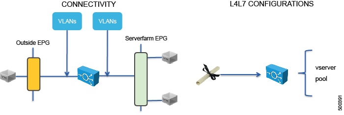
The service graph also defines the Layer 4 to Layer 7 configurations that must be loaded onto the Layer 4 to Layer 7 device.
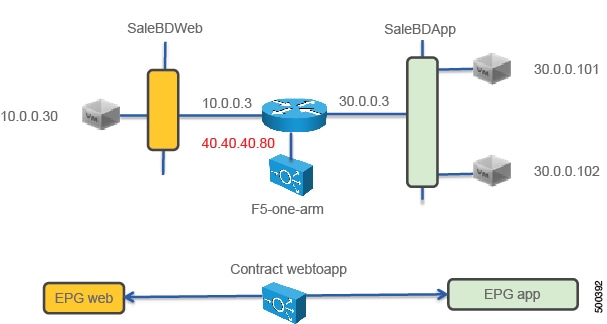
When deploying the F5 load balancer in one-arm mode, the contract is still defined between two endpoint groups, such as web and app as in Figure 2. The endpoint groups are associated with two bridge domains, such as SaleBDWeb (10.0.0.0/24) and SaleBDApp (30.0.0.0/24). The main difference with the other service graph modes is that the F5 device is attached to another bridge domain (40.40.40.0/24).
To deploy an F5 device in the one-arm mode, you must do the following things:
-
Configure 3 bridge domains with unicast routing enabled
-
Configure the F5 device as a GoTo device
-
Configure source NAT on the F5 device
-
Configure a VIP on the same subnet as the bridge domain to which the F5 connects
-
Configure the contract between the outside and inside endpoint group
-
Associate the service graph with the contract
-
Configure the logical interfaces external and internal to point to the same "internal" interface (1_2)
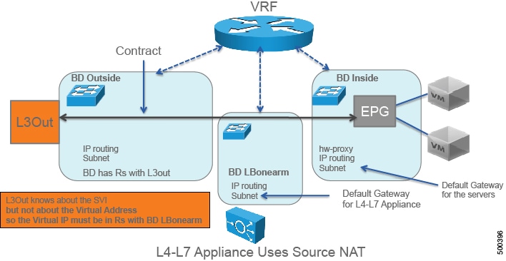
You could instead use the "external" interface. However, this document indicates to use the "internal" interface because if you want to enable endpoint attach, you must associate the internal interface to the bridge domain LBonearm.
-
Configure the logical device context to use the same bridge domain as the one connecting F5 to the VRF
The following figure illustrates the topology of the 3 bridge domains:
Overview of Preparing an F5 Device in One-Arm Mode
The following procedure provides of overview of preparing an F5 device to be deployed in one-arm mode.
Deploying F5 in One-Arm Mode
The tasks that you must perform to deploy F5 in one-arm mode are nearly identical to the tasks for generically deploying a service graph, with a few differences. The following procedure provides the generic service graph deployment tasks, along with information about what you must do differently to deploy F5 in one-arm mode.
| Step 1 | Create physical and virtual domains. |
| Step 2 | Configure the basic management access on the Layer 4 to Layer 7 device. |
| Step 3 | Import the device package. |
| Step 4 | Create the bridge domains
and VRFs.
See Creating Bridge Domains and VRFs Using the GUI. You must create 3 bridge domains:
|
| Step 5 | Create endpoint groups and contracts. |
| Step 6 | Configure logical devices
and concrete devices.
See Creating a Logical or Concrete Device Using the GUI. |
| Step 7 | Create or import a
function profile.
See Creating a Function Profile Using the GUI or Importing a Function Profile Using the GUI.
The following table describes the mandatory Layer 4 to Layer 7 parameters and provides examples of possible values that you must change for your specific configuration: The following XML is an example of a Layer 4 to Layer 7 parameters configuration: <!-- Note: some parameters are mandatory: -->
<!-- such as the Listener, the Pool, the Monitor, the virtual address, the load balancing method -->
<!-- without them the graph is not deployed -->
<!-- NETWORK FOLDER (called here Network1): SELFIP, STATIC ROUTE, NAT POOL -->
<!-- IP addresses for the F5 interfaces and default route we are just using the external interface here -->
<!-- The IP of the external inteface must be on the same subnet as the BD that connects to the VRF -->
<!-- In one-arm mode the configuration must use InternalSelfIP -->
<vnsFolderInst ctrctNameOrLbl="webtoapp" graphNameOrLbl="F5-onearm" key="Network" locked="no" name="Network1" nodeNameOrLbl="F5-1-node" scopedBy="epg">
<vnsFolderInst ctrctNameOrLbl="webtoapp" graphNameOrLbl="F5-onearm" key="InternalSelfIP" locked="no" name="InternalSelfIP" nodeNameOrLbl="F5-1-node" scopedBy="epg">
<vnsParamInst key="Floating" locked="no" name="Floating" value="NO"/>
<vnsParamInst key="SelfIPNetmask" locked="no" name="SelfIPNetmask" value="255.255.255.0"/>
<vnsParamInst key="SelfIPAddress" locked="no" name="SelfIPAddress" value="40.40.40.5"/>
<vnsParamInst key="PortLockdown" locked="no" name="PortLockdown" value="DEFAULT"/>
</vnsFolderInst>
<!-- STATIC ROUTE -->
<vnsFolderInst ctrctNameOrLbl="webtoapp" graphNameOrLbl="F5-onearm" key="Route" locked="no" name="Route" nodeNameOrLbl="F5-1-node" scopedBy="epg">
<vnsParamInst key="DestinationIPAddress" locked="no" name="DestinationIPAddress" value="0.0.0.0"/>
<vnsParamInst key="DestinationNetmask" locked="no" name="DestinationNetmask" value="0.0.0.0"/>
<vnsParamInst key="NextHopIPAddress" locked="no" name="NextHopIPAddress" value="40.40.40.3"/>
</vnsFolderInst>
<!-- SNAT IP ADDRESS, SNATPool1 is an arbitrary name referenced later -->
<vnsFolderInst ctrctNameOrLbl="webtoapp" graphNameOrLbl="F5-onearm" key="SNATPool" locked="no" name="SNATPool1" nodeNameOrLbl="F5-1-node" scopedBy="epg">
<vnsParamInst key="SNATIPAddress" name="SNATIPAddress" value="40.40.40.10"/>
</vnsFolderInst>
</vnsFolderInst>
<!-- END OF NETWORK FOLDER CONFIGURATION -->
<!-- LOCAL TRAFFIC FOLDER, called here LocalTrafficSSH -->
<!-- Definition of the load balancing mechanism, serverfarm and of monitoring-->
<vnsFolderInst ctrctNameOrLbl="webtoapp" graphNameOrLbl="F5-onearm" key="LocalTraffic" locked="no" name="LocalTrafficSSH" nodeNameOrLbl="F5-1-node" scopedBy="epg">
<!-- CONFIGURE HERE SERVER MONITORING called here "ICMPMonitor"-->
<vnsFolderInst ctrctNameOrLbl="webtoapp" graphNameOrLbl="F5-onearm" key="Monitor" locked="no" name="ICMPMonitor" nodeNameOrLbl="F5-1-node" scopedBy="epg">
<vnsParamInst key="Type" locked="no" name="ICMP" value="ICMP"/>
<vnsParamInst key="FailByAttempts" locked="no" name="FailByAttempts" value="3"/>
<vnsParamInst key="FrequencySeconds" locked="no" name="FrequencySeconds" value="5"/>
</vnsFolderInst>
<!-- CONFIGURE HERE THE LIST OF SERVERS called here "ServerPoolSSH"-->
<vnsFolderInst ctrctNameOrLbl="webtoapp" graphNameOrLbl="F5-onearm" key="Pool" locked="no" name="ServerPoolSSH" nodeNameOrLbl="F5-1-node" scopedBy="epg">
<!-- CONFIGURE HERE LOAD BALANCING TYPE -->
<vnsParamInst key="LBMethod" locked="no" name="LBMethod" value="ROUND_ROBIN"/>
<!-- Use Dynamic only if you want to use the EPG endpoints to autopopulate the serverfarm pool -->
<vnsParamInst key="PoolType" locked="no" name="PoolType" value="STATIC"/>
<!-- First Server in the Pool: Member1 -->
<vnsFolderInst ctrctNameOrLbl="webtoapp" graphNameOrLbl="F5-onearm" key="Member" locked="no" name="Member1" nodeNameOrLbl="F5-1-node">
<vnsParamInst key="Port" name="Port" value="22"/>
<vnsParamInst key="IPAddress" name="IPAddress" value="30.0.0.101"/>
</vnsFolderInst>
<!-- Second Server in the Pool: Member2 -->
<vnsFolderInst ctrctNameOrLbl="webtoapp" graphNameOrLbl="F5-onearm" key="Member" locked="no" name="Member2" nodeNameOrLbl="F5-1-node">
<vnsParamInst key="Port" name="Port" value="22"/>
<vnsParamInst key="IPAddress" name="IPAddress" value="30.0.0.102"/>
</vnsFolderInst>
<!-- This is a relation to the Pool Monitoring defined in "Monitor" -->
<vnsFolderInst ctrctNameOrLbl="webtoapp" graphNameOrLbl="F5-onearm" key="PoolMonitor" locked="no" name="ArbitraryNamePoolMonitor" nodeNameOrLbl="F5-1-node">
<vnsCfgRelInst key="PoolMonitorRel" locked="no" name="PoolMonitorRel" targetName="LocalTrafficSSH/ICMPMonitor"/>
</vnsFolderInst>
</vnsFolderInst>
</vnsFolderInst>
<!-- END OF LOCAL TRAFFIC FOLDER -->
<!-- MAIN FUNCTION CONFIG: here you define the Virtual IP, The Serverfarm, which Network config you want to use and the SNAT -->
<!-- Virtual IP for F5 (LISTENER) -->
<!-- In one-arm mode this must be on the same subnet as the BD that connects to the VRF -->
<vnsFolderInst ctrctNameOrLbl="webtoapp" graphNameOrLbl="F5-onearm" key="Listener" locked="no" name="ListenerSSH" nodeNameOrLbl="F5-1-node" scopedBy="epg">
<vnsParamInst key="DestinationPort" locked="no" name="DestinationPort" value="22"/>
<vnsParamInst key="Protocol" locked="no" name="Protocol" value="TCP"/>
<vnsParamInst key="DestinationNetmask" locked="no" name="DestinationNetmask" value="255.255.255.255"/>
<vnsParamInst key="DestinationIPAddress" locked="no" name="DestinationIPAddress" value="40.40.40.80"/>
<!-- This Virtual IP uses the source NAT from Network1 called SNATPool1-->
<vnsFolderInst ctrctNameOrLbl="webtoapp" graphNameOrLbl="F5-onearm" key="SNAT" name="ArbitraryNameNAT" nodeNameOrLbl="F5-1-node">
<vnsCfgRelInst key="SNATRel" name="SNATRel" targetName="Network1/SNATPool1"/>
<vnsParamInst key="SNATType" name="SNATType" value="SNAT_POOL"/>
</vnsFolderInst>
</vnsFolderInst>
<!-- Relation to the Serverfarm for F5 (which is defined within the LOCAL TRAFFIC)-->
<!-- This has a relation to "ServerPoolSSH" -->
<!-- If you don't put this configuration the Listener doesn't have any severfarm pool associated with it -->
<vnsFolderInst ctrctNameOrLbl="webtoapp" graphNameOrLbl="F5-onearm" key="Pool" locked="no" name="ArbitraryNameServerFarm" nodeNameOrLbl="F5-1-node" scopedBy="epg">
<vnsCfgRelInst key="PoolRel" locked="no" name="SSHserversforListenerSSH" targetName="LocalTrafficSSH/ServerPoolSSH"/>
<!-- These parameters are necessary -->
<!-- Change the destination L4PORT as needed -->
<vnsParamInst name="EPGDestinationPort" key="EPGDestinationPort" value="22" mandatory="no" />
<vnsParamInst name="EPGRatio" locked="no" key="EPGRatio" cardinality="unspecified" value="1" mandatory="no" />
<vnsParamInst name="EPGConnectionLimit" key="EPGConnectionLimit" value="1000" mandatory="no" />
<vnsParamInst name="EPGConnectionRateLimit" key="EPGConnectionRateLimit" value="1000" mandatory="no" />
</vnsFolderInst>
<!-- Network Relation for F5 -->
<!-- This defines the network configuration for this virtual server instance -->
<vnsFolderInst ctrctNameOrLbl="webtoapp" graphNameOrLbl="F5-onearm" key="NetworkRelation" locked="no" name="ArbitraryNameNetworkRelation" nodeNameOrLbl="F5-1-node" scopedBy="epg">
<vnsCfgRelInst key="NetworkRel" locked="no" name="NetworkRel" targetName="Network1"/>
</vnsFolderInst>
<!-- END OF MAIN FUNCTION CONFIG -->
|
| Step 8 | Create a service graph
template and either use a function profile or enter the Layer 4 to Layer 7
parameters by hand.
See Creating a Layer 4 to Layer 7 Service Graph Template Using the GUI.
|
| Step 9 | Apply the service graph
template.
See Applying a Service Graph Template to Endpoint Groups Using the GUI. You cannot configure an "any" virtual IP or port. You can only choose TCP or UDP option; there is no "all IP protocol" value. |
| Step 10 | Create the logical
device context (optional if you used the GUI wizard).
See Creating a Device Selection Policy Using the GUI. The following XML is an example of defining a logical device context: <!-- Connector name is defined in the Abstract Graph -->
<vnsLIfCtx connNameOrLbl="F5nodeclientside">
<vnsRsLIfCtxToLIf tDn="uni/tn-Sales/lDevVip-F5Cluster/lIf-F5ClusterExt”/>
<vnsRsLIfCtxToBD tDn="uni/tn-Sales/BD-LBBD"/>
</vnsLIfCtx>
<!-- Connector name is defined in the Abstract Graph -->
<vnsLIfCtx connNameOrLbl="F5nodeserverside">
<vnsRsLIfCtxToLIf tDn="uni/tn-Sales/lDevVip-F5Cluster/lIf-F5ClusterInt"/>
<vnsRsLIfCtxToBD tDn="uni/tn-Sales/BD-LBBD"/>
</vnsLIfCtx>
The highlighted lines select the bridge domain that connects to the VRF. |
| Step 11 | Verify that the configuration deployed successfully. |
Verifying the Configuration for an F5 Device
Undoing a Service Graph Configuration for F5
| Step 1 | In the
Application Policy Infrastructure Controller
(APIC)
GUI, delete the service graph template.
See Undoing a Service Graph Configuration Using the GUI. The F5 partitions are removed automatically, but you can remove them manually. |
| Step 2 | (Optional)To delete the partitions using the F5 GUI: |
| Step 3 | (Optional)To delete the
partitions using the F5 CLI:
|
 Feedback