Cisco APIC Layer 4 to Layer 7 Service Graph Deployment Guide, Release 1.2(2g)
Bias-Free Language
The documentation set for this product strives to use bias-free language. For the purposes of this documentation set, bias-free is defined as language that does not imply discrimination based on age, disability, gender, racial identity, ethnic identity, sexual orientation, socioeconomic status, and intersectionality. Exceptions may be present in the documentation due to language that is hardcoded in the user interfaces of the product software, language used based on RFP documentation, or language that is used by a referenced third-party product. Learn more about how Cisco is using Inclusive Language.
- Updated:
- April 20, 2016
Chapter: Overview
Overview
- About Service Graphs
- About the Service Graph Operational Model
- About Goto Devices and GoThrough Devices
- About Contracts
- About Device Packages
- About Virtual Appliances and Physical Appliances
- Dataplane
- About Multicontext Support
- About Sharing Service Devices
- About Unmanaged Mode
- Other Terminology
About Service Graphs
A service graph is an order set of Layer 4 to Layer 7 devices between two endpoint groups.
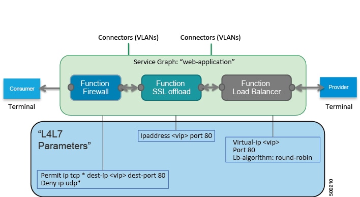
By using a service graph, you can install a service, such as the ASA firewall, once and deploy it multiple times in different logical topologies. Each time the graph is deployed, Cisco Application Centric Infrastructure (ACI) takes care of changing the configuration on the firewall to enable the forwarding in the new logical topology.
Deploying a service graph requires bridge domains and VRFs, as shown in the following figure:
- Advantages and Disadvantages of Using a Service Graph
- When to Use a Service Graph
- Methods for Configuring a Service Graph
- About Multi-Node Service Graphs
Advantages and Disadvantages of Using a Service Graph
Using a service graph provides several advantages and some disadvantages over not using one.
The advantages are as follows:
-
Is a configuration template that can be reused multiple times
-
Provides a more logical view and an application-related view of services
-
Can provision a device that is shared across multiple departments
-
Automatically manages VLAN assignments
-
Automatically plugs vNICs
-
Collects health scores from the device or service
-
Collects statistics from the device
-
Updates ACLs and pools automatically with endpoint discovery
-
Can use unmanaged mode to avoid using a device package
The disadvantages are as follows:
When to Use a Service Graph
A service graph is most often used for the following things:
-
Automation
-
Integration of Cisco Application Centric Infrastructure (ACI) and services for advanced features
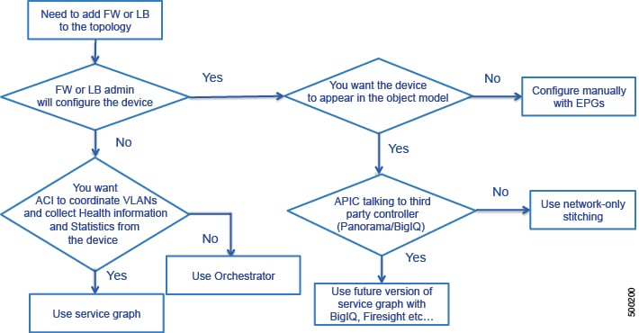
You do not need to use a service graph all of the time. For example, you might want to use unmanaged mode or you might only want to create endpoint groups and plug a firewall and load balancer into the endpoint groups. In such cases, you do not need a service graph.
The following flowchart can help you determine if you should use a service graph:
Methods for Configuring a Service Graph
You can configure a service graph by using the following methods:
-
GUI—If you are learning how to configure a service graph or if you are using predefined function profiles, you can use the GUI to validate the configuration and then save the service graph in XML format.
-
REST API—Use the REST API in a production environment by integrating REST calls into Python scripts to automate the provisioning of a service graph.
About Multi-Node Service Graphs
You can configure a multi-node service graph, which is a service graph that has more than one Layer 4 to Layer 7 service. The following figure illustrates the bridge domain configuration of a multi-node service graph:
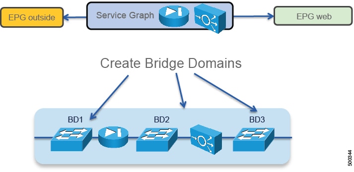
The bridge domains act as the links between the Layer 4 to Layer 7 devices.
 Note | The GUI enables you to configure multi-node service graphs consisting of 2 nodes, while the REST API enables you to configure up to 3 nodes in a single service graph. |
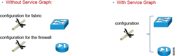
About the Service Graph Operational Model
You use a different operational model when you use a service graph compared to not using a service graph. Without a service graph, you use the following operational model:
-
The network administrator configures the ports and VLANs to connect the firewall or the load balancer.
-
On day 0, the firewall administrator configures the ports and VLANs.
-
On day 1, the firewall administrator configures the ACLs and other components.
-
The three configurations are spread over multiple days.
With a service graph, you use the following operational model:
-
The Cisco Application Centric Infrastructure (ACI) administrator configures the ports and VLANs to connect the firewall or the load balancer.
-
The firewall administrator configures the ports, VLANs, ACLs, and other components.
-
All configurations are performed in a single step.
The following figure illustrates how the operational model changes when you use a service graph:
The following figure illustrates the operational model of network administration without Cisco Application Centric Infrastructure (ACI):

The network administrator uses a network management tool to configure each individual network.
The following figure illustrates the operational model of Layer 4 to Layer 7 services administration without ACI:

The load balancer or firewall administrator uses a Layer 4 to Layer 7 management tool to configure a load balancer or firewall for each individual network.
The following figure illustrates the operational model of Layer 4 to Layer 7 services administration with ACI:
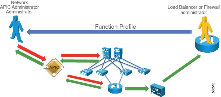
The load balancer or firewall administrator creates a function profile that the Application Policy Infrastructure Controller (APIC) administrator uses in the APIC to configure a network, firewall, or load balancer. A function profile provides the default values for a service graph template.
The following figure illustrates the operational model of Layer 4 to Layer 7 services administration with ACI using automation:
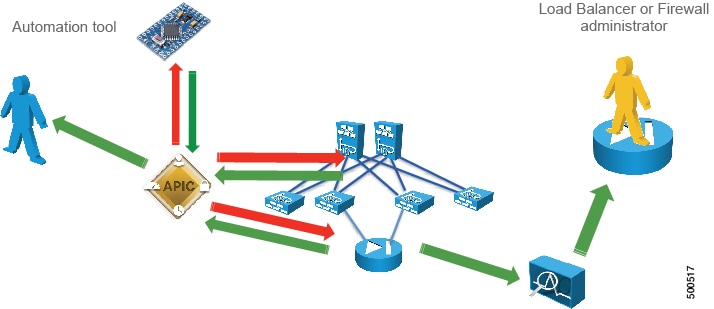
The APIC administrator uses an automation tool that uses a function profile to configure all networks, firewalls, and load balancers.
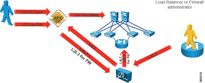
In all of these models, the APIC administrator wants control over the network, while the load balancer or firewall administrator wants control over the load balancer or firewall.
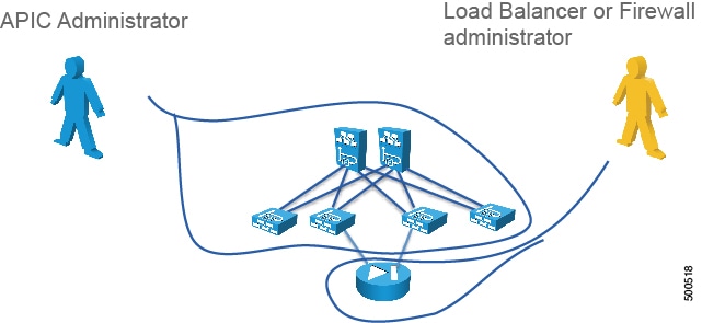
The solution to this issue is to deploy Layer 4 to Layer 7 services with a device manager, as shown in the following figure:
About Goto Devices and GoThrough Devices
You can configure a logical device as one of the following function types:
About Contracts
Contracts define inbound and outbound permit, deny, and QoS rules between endpoint groups. Contracts allow both simple and complex definition of the way that an endpoint group communicates with other endpoint groups. Contracts connect endpoint groups using a provider-consumer relationship. One endpoint group provides a contract and other endpoint groups consume that contract, and each endpoint group is associated with a bridge domain. The service graph is always associated with a contract, thus connecting a client-side (outside) or consumer endpoint group to a server-side (inside) provider endpoint group.
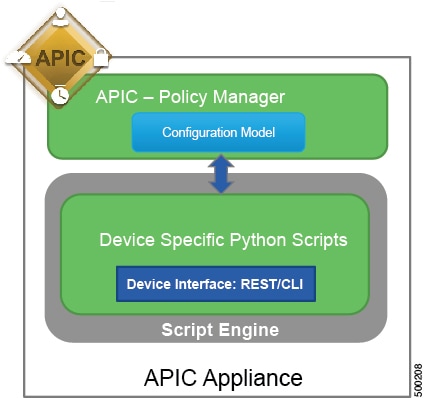
About Device Packages
The Application Policy Infrastructure Controller (APIC) requires a device package to configure and monitor service devices. You add service functions to the APIC through the device package.
A device package contains a device configuration model and device scripts. A device configuration model is an XML file that defines a service function and configuration. A device script is a Python script that translates APIC API callouts to device-specific callouts. A device script can interface with the device by using REST, SSH, or any similar mechanism.
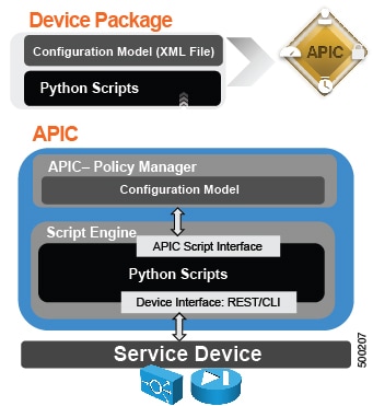
The functions in a device script are classified into the following categories:
-
Device/Infrastructure—For device level configuration and monitoring
-
Service Events—For configuring functions, such as a server load balancer or Secure Sockets Layer, on the device
-
Endpoint/Network Events—For handling endpoint and network attach/detach events
The APIC uses the device configuration model that is provided in the device package to pass the appropriate configuration to the device scripts. The device script handlers interface with the device using its REST or CLI interface.
For more information about device packages and how to develop a device package, see Cisco APIC Layer 4 to Layer 7 Device Package Development Guide
About Device Package Versions
Each device package has three types of versions:
-
Major Version—Multiple major versions can co-exists in an Application Policy Infrastructure Controller (APIC). For example, ACME 9000 and ACME Chassis-10000 can have different packages with different major versions.
The following XML string shows a major version:
<vnsMDev vendor="Acme" model="ADC" version="10.5">
-
Minor Version—Represents a different version of the packages for the same major version. Only one minor version can be active in an APIC at a given time. The minor version is used to do versioning of software releases of a device package for a specific major version.
-
ctrlrVersion—When a package is developed, it is developed against a specific APIC version. The APIC validates this in the policymgr against the APIC's running version. The package upload fails if there is a mismatch.
The following XML string shows a minor version and ctrlrVersion:
<vnsDevScript name="Acme" packageName="AcmeDeviceScript.py"
  minorversion="10.51" ctrlrVersion="1.0"/>
About Device Package Upgrades
You can upgrade a device package by uploading a new one to the Application Policy Infrastructure Controller (APIC). The device package version is a concatenation of the controller version and device package minor version. The first part of the device package version (1.0 in the ASA example) should be greater than or equal to the APIC version.
If the major version (the naming property of class vnsMDev) changes, uploading the device package will create a new device package. For example, if the original ASA package distinguished name was "uni/infra/mDev-CISCO-ASA-1.0" and the new package version changed to "2.0", then the new distinguished name will be "uni/infra/mDev-CISCO-ASA-2.0". The system will have two packages; the old service graphs and device clusters will continue to point to the old package and continue working. New service graphs and device clusters can use the old or new device package. Switching the old service graphs and device clusters to the new package will be disruptive.
Changing the minor version (a property called minorversion in the DevScript managed object) does not change the distinguished name of the package or vnsMDev. Uploading a new device package with a different minorversion overwrites the existing device package. All service graphs and device clusters that pointed to the old device package start pointing to the new device package automatically. The upgrade is non-disruptive and there should be no impact for existing service graphs or device clusters. A minor version change is the default recommendation for partners for any new package revisions.
When the APIC identifies that only the minor version has changed and that the device package version has not incremented, the APIC takes the following actions:
-
Existing service graph instances using the existing device packages are terminated
-
The script wrapper process hosting the device script is terminated and a new script wrapper process is initiated
-
New graph instances are created
-
Device audit and service audit is invoked on all of the new graph instances
The following table provides a recommendation for whether a device package change should be a major version or minor version change:
|
Type of Change in Device Package |
Recommended Upgrade Type |
|---|---|
|
Script bug fixes |
Minor version |
|
Addition of any kind, such as new functions, folders, parameters, or profiles |
Minor version |
|
Modification or removal of any kind, such as functions, folder/parameters, or profiles |
Major version |
APIC images are backward compatible with old device packages. If a device package is already uploaded and an APIC is upgraded, the old device package continues to work without any disruption. Newer device packages might not work on older versions; in such cases, the device package upload step fails with an appropriate error.
About Virtual Appliances and Physical Appliances
The following table compares virtual appliances and physical appliances:
|
Virtual Appliance |
Physical Appliance |
|---|---|
|
Cannot trunk on the vNIC |
Supports trunking on the physical interfaces |
|
If you need to use the service graph across multiple bridge domains: |
The service graph can be re-used across multiple bridge domains |
Virtual Appliances
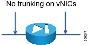
vNICs are automatically assigned to the port-groups. VLANs are automatically created on the ACI interfaces and on the Layer 4 to Layer 7 device. You cannot reuse the same graph on different bridge domains. There is no trunking on the vNICs, as shown in the following figure:
A service graph with virtual appliances works with virtual appliances running on a VMware vSphere Distributed Switch (VDS) or Cisco Application Virtual Switch (AVS) with VLANs.
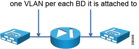
Physical Appliances
When you deploy a physical appliance, VLANs are automatically created on the Cisco Application Centric Infrastructure (ACI) interfaces and on the Layer 4 to Layer 7 device. One VLAN gets created for each bridge domain to which the physical appliance is attached, as shown in the following figure:
Dataplane
About Deployment Modes
There are three main deployment modes for a service graph:
-
GoTo—The Layer 4 to Layer 7 device is a Layer 3 device that routes traffic; it is the default gateway for servers or the next hop
-
GoThrough—The Layer 4 to Layer 7 device is a transparent Layer 2 device; the next-hop or the outside bridge domain provides the default gateway
-
One-arm—The bridge domain of the servers is the default gateway
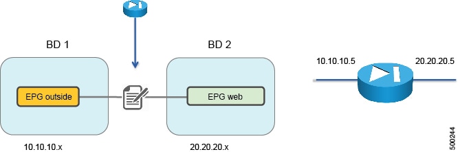
Except for one-arm mode, you must start with two bridge domains, as shown in the following figure:
GoTo Mode
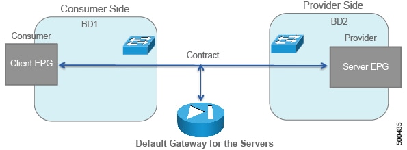
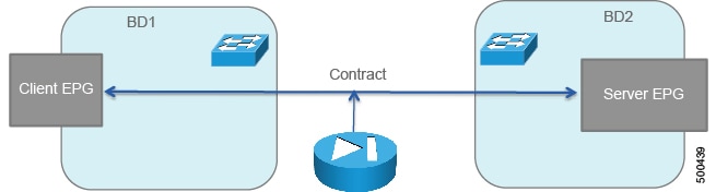
The following figure illustrates a generic GoTo mode deployment with its basic building blocks:
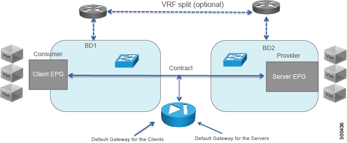
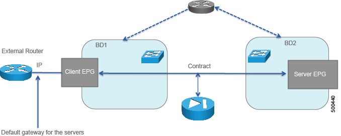
The following figure illustrates a GoTo mode deployment with client virtual machines, including the fact that you must provision VRFs to be associated with the bridge domains:
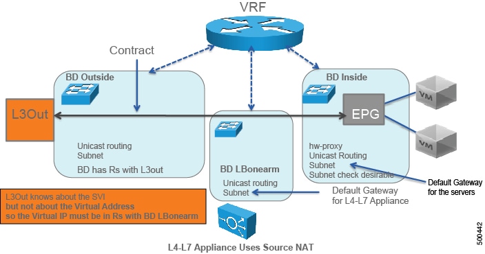
The following figure illustrates a GoTo mode deployment with a Layer 3 Outside (L3Out):
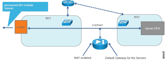
The L3Out consumes the contract through the Layer 3 external endpoint group, which is called L3InstP in the object model.
The bridge domain has a "Rs" with the L3Out, which indicates that in the bridge domain configuration, you must indicate with which L3Out the bridge domain is associated.
The following figure illustrates a GoTo mode deployment with an external router:
GoThrough
The following figure illustrates a GoThrough mode deployment with its basic building blocks:
The following figure illustrates a GoThrough mode deployment with an external router, including the fact that you must provision VRFs to be associated with the bridge domains:
The following figure illustrates a GoThrough mode deployment with a Layer 3 Outside (L3Out):

The L3Out consumes the contract through the Layer 3 external endpoint group, which is called L3InstP in the object model.
One-Arm Mode
The following figure illustrates a one-arm mode deployment:
The topology for a one-arm mode deployment is as follows:
About Configuring Bridge Domains
With a service graph, you must configure a bridge domain for the client-side/consumer-side/outside, a bridge domain for the server-side/provider-side/inside, and bridge domains to stitch devices.
If you do not know which bridge domain settings to use, you can use the following:
This is a valid configuration, but it might not be the best configuration for your setup. For more information about how to optimize the bridge domain configurations, see Deploying F5 and Deploying ASA.
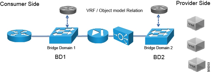
Determining the Number of VRFs to Use
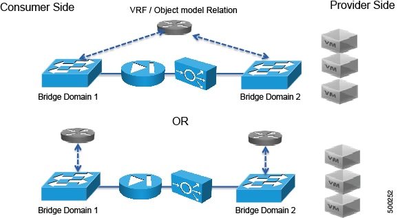
In Cisco Application Centric Infrastructure (ACI), each bridge domain must always be associated to a VRF for the purpose of meeting the object model requirements. Each VRF has one or more bridge domains associated with it and when the bridge domains are configured for routing, the traffic of one bridge domain can be routed to another bridge domain of the same VRF. You must therefore determine how many VRFs to use when deploying the service graph.
To decide how many VRFs that you need, you must understand how endpoint IP learning works:
-
If routing is disabled under the bridge domain, then ACI only learns the MAC address.
-
If routing is enabled under the bridge domain, then ACI learns the MAC address with Layer 2 traffic. ACI also learns the IP address when the host sends an ARP request to another host.
-
Layer 2 traffic forwarding is still only based on the DMAC.
-
The mapping database learns the IP address, which can be useful for troubleshooting and other functions.
The following figure illustrates how the mapping database gets programmed if 10.0.0.102 sends traffic:
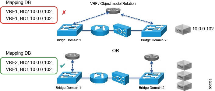
As Figure 2 shows, if you are deploying services and you have IP routing enabled on both bridge domains (1 and 2), you must create a VRF for each bridge domain that has IP routing enabled.
About the Subnet Check
You can enforce the subnet check for IP address learning, which causes ACI to learn only IP addresses from configured subnets. This limits the IP address learning in the bridge domain to the IP addresses of the subnet that is specified. The other IP addresses are still forwarded, but are based on their MAC addresses and are not based on their IP addresses.
About Hardware Proxy
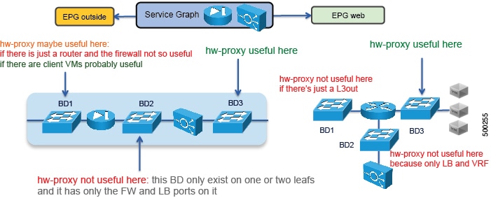
The hardware proxy feature reduces flooding for Layer 2 unknown unicast packets. If the Layer 4 to Layer 7 appliance must be able to see flooded packets, then you cannot use hardware proxy. Otherwise, you can enable the hardware proxy on bridge domains that span multiple leafs to reduce the amount of flooded packets. Tuning the bridge domain to reduce packet flooding is beneficial when deploying the service graph in GoTo mode. When using GoThrough mode, Cisco Application Centric Infrastructure (ACI) automatically sets the bridge domains in unknown unicast flooding mode.
The following figure provides some examples of bridge domains for which hardware proxy can be beneficial:
About Multicontext Support
Multicontext support enables the same physical appliance to be exported to multiple tenants. You can create multiple partitions with a virtual appliance, but the vNICs cannot be shared because the virtual appliance is on multiple tenants, which means that there cannot be a trunk with VLANs on the same vNIC.
With ASA, you can partition a single physical ASA into multiple virtual firewalls, known as security/virtual contexts. Each context acts as an independent device with its own security policy, interfaces, and management IP address. The Application Policy Infrastructure Controller (APIC) does not create the ASA contexts; they must be predefined. Allocate-interface on the system context, firewall configuration on a virtual context, and the Cisco Application Centric Infrastructure (ACI) fabric policy are done by the APIC. The APIC needs to communicate with the system context and each virtual context.
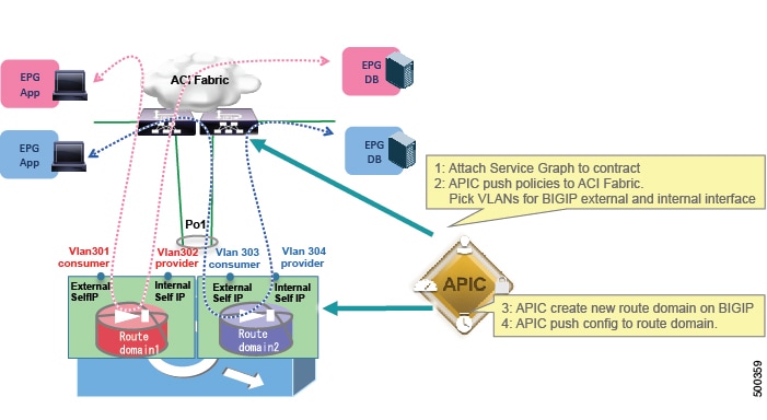
With F5, partitions are automatically created and ACI tenants are automatically mapped to an F5 partition.
About Multicontext Support and Dataplane Separation
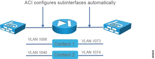
The Application Policy Infrastructure Controller (APIC) creates sub-interfaces based on a dynamically allocated VLAN from a pool, and in the system context it assigns port-channel sub-interfaces to appropriate user contexts. The following figure illustrates dataplane separation:
The following figure illustrates how Cisco Application Centric Infrastructure (ACI) manages a multi-context ASA firewall:
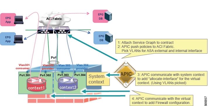
In the case of the ASA firewall, the APIC does not create the virtual context; they must be predefined. Allocate-interface, firewall configuration on a virtual context, and the ACI fabric policy are done by the APIC. The APIC needs to communicate with the system context and each virtual context.
The following figure illustrates how ACI manages multiple contexts with F5 BIGIP:
About Sharing Service Devices
Cisco Application Centric Infrastructure (ACI) lets you configure objects in tenant Common that can be used by other tenants. Some of the objects include filters, bridge domains, VRFs, logical devices, and concrete devices. Tenants can attach endpoint groups to these objects. The following figure illustrates other tenants using objects that are configured in tenant Common:
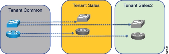
With multicontext devices, you can share a device that is defined in tenant Common and use it from more than one tenant.
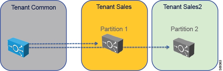
In addition to using tenant Common to share devices, you can also export contracts and Layer 4 to Layer 7 devices from any tenant for other tenants to use.
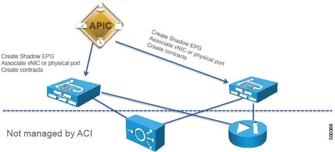
About Unmanaged Mode
You can define a Layer 4 to Layer 7 service as unmanaged. With the unmanaged mode, Cisco Application Centric Infrastructure (ACI) only configures the fabric, not the Layer 4 to Layer 7 device.
For more information about the unmanaged mode, see Cisco APIC Layer 4 to Layer 7 Services Deployment Guide .
Other Terminology
This section provides a high level description of other terminology that is not discussed in great detail in this document.
- Concrete Device
-
Represents a service device, such as one load balancer or one firewall. It can be physical or virtual. Concrete devices are the devices member of a cluster, appear as child of the logical device, and own the physical or virtual interfaces. A concrete device defines concrete interfaces and maps an interface to a virtual adapter or path. A concrete device defines device-wide parameters, such as an HA or cluster configuration for ASA.
- Logical Device
-
Represents a cluster of 2 devices that operate in active/standby mode. A logical device defines logical interfaces. The logical interface type is defined in the device model, and logical interfaces are used for the device selection policy. A logical device also defines cluster-wide parameters where applicable, such as NTP and DNS.
Note
HA configuration is done on the concrete device on ASA.
- Function Node
-
These nodes are functions of a device that are defined by the device package. A function node defines the configuration options that are available. Service graphs can contain one or more function nodes.
- Function Node Connector
-
Each function node connector is allocated a VLAN by Cisco Application Centric Infrastructure (ACI); you do not need to manage that VLAN. A function node connector must be associated with a bridge domain. The user must have predefined the bridge domain and reference it in the configuration. Each side of function node connector is treated as an endpoint group and ACI automatically creates the endpoint group (shadow endpoint group) and puts a contract between the shadow endpoint group and the endpoint group created by the user.
- Logical Device Context
-
Also known as a device selection policy, a logical device context selects the appropriate logical device and interfaces based on the following selectors:
- Service Graph Connection
-
Service graph connections are used when multiple nodes are link. They act as a cable in-between 2 nodes (AbsFConn). The cable can be Layer 2 or Layer 3, with or without unicast routing.
- Service Graph Template
-
A generic representation of the expected traffic flow that defines connection points (connections and terminals) and the sequence of nodes and functions. A service graph template must be applied for it to be rendered.
- Terminal
-
Terminals define the consumer (AbsTermNodeCon) and provider (AbsTermNodeProv) links to the contract. Terminals need a connection to the node.
 Feedback