Cisco Physical Security Multiservices Platform Series User Guide
Bias-Free Language
The documentation set for this product strives to use bias-free language. For the purposes of this documentation set, bias-free is defined as language that does not imply discrimination based on age, disability, gender, racial identity, ethnic identity, sexual orientation, socioeconomic status, and intersectionality. Exceptions may be present in the documentation due to language that is hardcoded in the user interfaces of the product software, language used based on RFP documentation, or language that is used by a referenced third-party product. Learn more about how Cisco is using Inclusive Language.
- Updated:
- January 6, 2011
Chapter: 16 x D1 / 8 x D1 video capture cards
- Before You Begin
- Overview
- Requirements
- Features
- Encoding Parameter Limitations
- Motion Detection with Low Quality Cameras
- Video Card Connector and LED
- Understanding Video Channel Numbers
- Connecting the Video Capture Card to the BNC Breakout Panel
- Part Numbers
- Specifications
- Configuration Instructions for Cisco Video Surveillance
16 x D1 and 8 x D1 Video Capture Cards
The 16 x D1 and 8 x D1 video capture cards capture and compress standard definition analog video streams, and are available in the following configurations:
•![]() CIVS-ENC-8P—8 channel video capture card
CIVS-ENC-8P—8 channel video capture card
•![]() CIVS-ENC-16P—16 channel video capture card
CIVS-ENC-16P—16 channel video capture card
Each card can capture full-resolution standard video on all available channels at full frames-per-second.
This document includes the following topics:
•![]() Encoding Parameter Limitations
Encoding Parameter Limitations
•![]() Motion Detection with Low Quality Cameras
Motion Detection with Low Quality Cameras
•![]() Understanding Video Channel Numbers
Understanding Video Channel Numbers
•![]() Connecting the Video Capture Card to the BNC Breakout Panel
Connecting the Video Capture Card to the BNC Breakout Panel
•![]() Configuration Instructions for Cisco Video Surveillance
Configuration Instructions for Cisco Video Surveillance
Before You Begin
Before connecting or configuring the 16 x D1 and 8 x D1 video capture cards, review the following guidelines:
•![]() The video capture cards are available as an option for the Multiservices Platform Series Series 1-RU (CPS-MSP-1RU-K9) and 2-RU (CPS-MSP-2RU-K9) models only.
The video capture cards are available as an option for the Multiservices Platform Series Series 1-RU (CPS-MSP-1RU-K9) and 2-RU (CPS-MSP-2RU-K9) models only.
•![]() The Multi Services Platform Series Device that contains the video capture card must be installed and located in a designated restricted access location.
The Multi Services Platform Series Device that contains the video capture card must be installed and located in a designated restricted access location.
•![]() If the coaxial cable that is connected to a camera is located on the building exterior, the coaxial cable shield must be connected to earth (grounded) at the entrance to the building. The shield connection should be done in accordance with applicable national electrical installation codes. In the United States, this shield connection is required by Section 820.93 of the National Electrical Code, ANSI/NFPA 70. All grounding points should be of same voltage potential.
If the coaxial cable that is connected to a camera is located on the building exterior, the coaxial cable shield must be connected to earth (grounded) at the entrance to the building. The shield connection should be done in accordance with applicable national electrical installation codes. In the United States, this shield connection is required by Section 820.93 of the National Electrical Code, ANSI/NFPA 70. All grounding points should be of same voltage potential.
•![]() To meet the European alarm specification EN50130-4, an uninterruptible power supply (UPS) is required for stabilizing power interruptions. APC model number SUA2200I or equivalent must be used with the Multiservices Platform Series that contains the video capture card.
To meet the European alarm specification EN50130-4, an uninterruptible power supply (UPS) is required for stabilizing power interruptions. APC model number SUA2200I or equivalent must be used with the Multiservices Platform Series that contains the video capture card.
•![]() The Multiservices Platform Series that contains the video capture card must be installed by a service person. All equipment must be connected to a socket outlet with a protective earthing connection.
The Multiservices Platform Series that contains the video capture card must be installed by a service person. All equipment must be connected to a socket outlet with a protective earthing connection.
•![]() Analog cameras with pan-tilt-zoom (PTZ) controls require a serial connection. See the "Connecting and Configuring Analog PTZ Cameras" section for more information.
Analog cameras with pan-tilt-zoom (PTZ) controls require a serial connection. See the "Connecting and Configuring Analog PTZ Cameras" section for more information.
Overview
The 16 x D1 and 8 x D1 video capture cards are factory installed in the following Multiservices Platform Seriess:
•![]() 1-RU Multiservices Platform Series (CPS-MSP-1RU-K9)—Supports a single 8 or 16 channel encoder card.
1-RU Multiservices Platform Series (CPS-MSP-1RU-K9)—Supports a single 8 or 16 channel encoder card.
•![]() 2-RU Multiservices Platform Series (CPS-MSP-2RU-K9)—Supports 8 or 16 channel encoder cards installed in three slots. The supported card configurations are for 8, 16, 24, 32, 40, or 48 channels.
2-RU Multiservices Platform Series (CPS-MSP-2RU-K9)—Supports 8 or 16 channel encoder cards installed in three slots. The supported card configurations are for 8, 16, 24, 32, 40, or 48 channels.
Figure E-1 shows the rear of the Multiservices Platform Series with the video capture card installed. The circled area shows the location of the cards and I/O connectors.
Figure E-1 1-RU and 2-RU Multi Services Platform Series Devices with Optional Video Capture Card Installed
|
|
1-RU Multiservices Platform Series (CPS-MSP-1RU-K9) |
|
2-RU Multiservices Platform Series (CPS-MSP-2RU-K9) |


Note![]() •
•![]() The 16 x D1 and 8 x D1 video capture cards are preinstalled in Multiservices Platform Seriess and are not available as an upgrade to existing installations. Field replaceable units (FRUs) are available for the same card, but you cannot upgrade an existing card to a different type. Replacement cards must be installed in the same server slot as the removed card.
The 16 x D1 and 8 x D1 video capture cards are preinstalled in Multiservices Platform Seriess and are not available as an upgrade to existing installations. Field replaceable units (FRUs) are available for the same card, but you cannot upgrade an existing card to a different type. Replacement cards must be installed in the same server slot as the removed card.
•![]() Audio is not supported by the 16 x D1 and 8 x D1 video capture cards.
Audio is not supported by the 16 x D1 and 8 x D1 video capture cards.
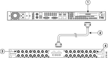
Cisco recommends that a separate BNC breakout panel be used to provide BNC connectors for the cameras. The breakout panel should be rack-mounted behind the server and connected to the video capture card with a DB37 multi-channel video cable, as shown in Figure E-2. See the "Connecting the Video Capture Card to the BNC Breakout Panel" section for more information.
Figure E-2 Multi Services Platform Series Devices with Optional Video Capture Card, BNC Panel, and Connecting Cable
|
|
1-RU Multiservices Platform Series with installed video capture card |
|
|
2-RU Multiservices Platform Series with installed video capture card |
|
|
Multi-channel video cables |
|
|
BNC breakout panels |

See the "Part Numbers" section for more information.
Requirements
The following items are required to support the 16 x D1 and 8 x D1 video capture cards.
•![]() Cisco VSM release 6.3 or higher. See the "Configuration Instructions for Cisco Video Surveillance" section.
Cisco VSM release 6.3 or higher. See the "Configuration Instructions for Cisco Video Surveillance" section.
•![]() CPS-MSP-1RU-K9 or CPS-MSP-2RU-K9 Multiservices Platform Series with one or more 16 x D1 and 8 x D1 video capture cards.
CPS-MSP-1RU-K9 or CPS-MSP-2RU-K9 Multiservices Platform Series with one or more 16 x D1 and 8 x D1 video capture cards.
•![]() BNC breakout panel and multi-channel video cable.
BNC breakout panel and multi-channel video cable.
See the "Part Numbers" section for more information.
Features
The 16 x D1 and 8 x D1 video capture cards include the following features:
•![]() Support for all encoding features in Cisco VSM release 6.3 and higher
Support for all encoding features in Cisco VSM release 6.3 and higher
•![]() Support for H.264 and Motion JPEG compression
Support for H.264 and Motion JPEG compression
–![]() Video streams with Motion JPEG compression support up to 15 fps
Video streams with Motion JPEG compression support up to 15 fps
–![]() Primary streams with H.264 compression support up to 30 fps @ D1
Primary streams with H.264 compression support up to 30 fps @ D1
–![]() Secondary streams with H.264 compression support up to 15 fps @ 2CIF
Secondary streams with H.264 compression support up to 15 fps @ 2CIF
•![]() Video motion detection (VMD) on each primary video stream
Video motion detection (VMD) on each primary video stream
•![]() Up to four motion detection windows can be configured for each video stream
Up to four motion detection windows can be configured for each video stream
•![]() Dynamic configuration change without reboot
Dynamic configuration change without reboot
•![]() NTSC and PAL support
NTSC and PAL support
|
Note |
Encoding Parameter Limitations
Table E-1 lists the limitations for resolutions and bitrate, and frame rate.
Motion Detection with Low Quality Cameras
Video containing large amounts of visual noise (sometimes caused by low quality cameras) may be prone to triggering false motion events. Use low sensitivity motion detection settings to capture only motion events of interest.
Video Card Connector and LED
The 16 x D1 and 8 x D1 video capture cards provide DB37 connectors for attaching analog cameras. To connect video cameras, Cisco recommends connecting a multi-channel video cable to a Cisco BNC breakout panel, as shown in Figure E-3.
Figure E-3 1-RU and 2-RU Multi Services Platform Series Devices
|
|
LED light |
|
|
DB37 connector |
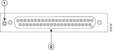
The card LED has the following states:
•![]() Green—Power to the card is on and the card passed a power-up self-test
Green—Power to the card is on and the card passed a power-up self-test
•![]() Yellow—Power to the card is on but card failed the power-up self-test
Yellow—Power to the card is on but card failed the power-up self-test
•![]() Not lit—Power to the card is off
Not lit—Power to the card is off
Understanding Video Channel Numbers
Channel numbers are defined by the server expansion slot where the card is installed. This section includes the following topics:
•![]() 1-RU Multi Services Platform Series Device Channel Numbers
1-RU Multi Services Platform Series Device Channel Numbers
•![]() 2-RU Multi Services Platform Series Device Channel Numbers
2-RU Multi Services Platform Series Device Channel Numbers
 |
Tip |
1-RU Multi Services Platform Series Device Channel Numbers
In a 1-RU Multiservices Platform Series, there is a single slot for either a 16 or 8 channel video capture card. Connect a multi-channel video cable from the server video card to the top DB37 connector on a BNC breakout panel, as shown in Figure E-4. The corresponding top row of connectors on the BNC panel are labeled 1 through 16. If an 8-channel video capture card is installed, only ports 1 through 8 on the BNC panel are used.
Figure E-4 1-RU Multi Services Platform Series Device Video Capture Card Port Numbers
|
|
Video capture connection for the 1-RU Multiservices Platform Series (ports 1 through 16) |
|
BNC panel port numbers 1 through 8 |
|
|
DB37 multi-channel video cable |
|
BNC panel port numbers 9 through 16 |
|
Note |
2-RU Multi Services Platform Series Device Channel Numbers
In a 2-RU Multiservices Platform Series, there are three slots for 16 and 8 port video capture cards. Figure E-5 shows the location of the video cards, and the corresponding connections to the BNC breakout panels.
Figure E-5 2-RU Multi Services Platform Series Device Video Capture Card Port Numbers

Figure E-6 shows the location of the video cards, and the corresponding connections to the BNC breakout panels.
Figure E-6 Channel Numbers for the 2-RU Multi Services Platform Series Device
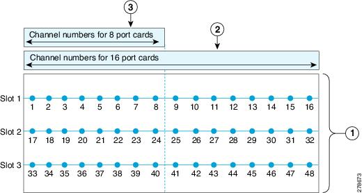
Table E-2 shows the possible video capture card combinations in a 2-RU Multiservices Platform Series.
Connecting the Video Capture Card to the BNC Breakout Panel
The BNC breakout panel provides connections for the BNC cables from the analog cameras.
To connect the BNC breakout panel to the 16 x D1 or 8 x D1 video capture cards, complete the following procedure.
Procedure
Step 1 ![]() Purchase and rack-mount the server with one or more factory installed 16 x D1 or 8 x D1 video capture cards.
Purchase and rack-mount the server with one or more factory installed 16 x D1 or 8 x D1 video capture cards.
See the "Part Numbers" section for a list of supported servers and cards.
Figure E-7 CPS-MSP-1RU-K9 and CPS-MSP-2RU-K9 with Optional Video Capture Card Installed

Step 2 ![]() Rack-mount the BNC breakout panel behind the server.
Rack-mount the BNC breakout panel behind the server.
Figure E-8 shows the panel and connections.
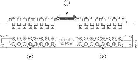
Figure E-8 BNC Breakout Panel
|
|
Two DB37 receptacles for the multi-channel video cables that connect to the video capture cards |
|
|
BNC connectors for the video camera coaxial cables |
Step 3 ![]() Attach a CIVS-CAB-16V multi-channel video cable from each video capture card to the BNC breakout panel.
Attach a CIVS-CAB-16V multi-channel video cable from each video capture card to the BNC breakout panel.
Note![]() •
•![]() The same multi-channel video cable is used for 8 or 16 channel cards.
The same multi-channel video cable is used for 8 or 16 channel cards.
•![]() Video capture channels are defined by the location of the card in the server, not the numbers labeled on the BNC panel. See the "Understanding Video Channel Numbers" section for more information.
Video capture channels are defined by the location of the card in the server, not the numbers labeled on the BNC panel. See the "Understanding Video Channel Numbers" section for more information.
Figure E-9 DB37 Receptacles on Rear of BNC Breakout Panel

Step 4 ![]() Attach coaxial cables from the video cameras to the appropriate port on the BNC breakout panel.
Attach coaxial cables from the video cameras to the appropriate port on the BNC breakout panel.
Figure E-10 Front of BNC Breakout Panel: BNC Connectors

Note![]() •
•![]() The video encoder channels are determined by the installed location of the card, not by the numbers on the BNC panel. See the "Understanding Video Channel Numbers" section for more information. For example, if three video capture cards are installed in a 2-RU server, the bottom card can be attached to the top connector of a second BNC panel. The channel numbers for this bottom video are 33 to 48, even though the BNC panel shows ports 1 to 16.
The video encoder channels are determined by the installed location of the card, not by the numbers on the BNC panel. See the "Understanding Video Channel Numbers" section for more information. For example, if three video capture cards are installed in a 2-RU server, the bottom card can be attached to the top connector of a second BNC panel. The channel numbers for this bottom video are 33 to 48, even though the BNC panel shows ports 1 to 16.
•![]() If the camera or coaxial cable is installed on the building exterior, the coaxial cable shield must be connected to earth (grounded) at the entrance to the building. The shield connection should be done in accordance with applicable national electrical installation codes. In the United States, this shield connection is required by Section 820.93 of the National Electrical Code, ANSI/NFPA 70.
If the camera or coaxial cable is installed on the building exterior, the coaxial cable shield must be connected to earth (grounded) at the entrance to the building. The shield connection should be done in accordance with applicable national electrical installation codes. In the United States, this shield connection is required by Section 820.93 of the National Electrical Code, ANSI/NFPA 70.
|
Tip |
Step 5 ![]() If the analog camera also includes PTZ controls, connect the camera serial cable to the Multiservices Platform Series serial port, as described in the "Connecting and Configuring Analog PTZ Cameras" section.
If the analog camera also includes PTZ controls, connect the camera serial cable to the Multiservices Platform Series serial port, as described in the "Connecting and Configuring Analog PTZ Cameras" section.
Step 6 ![]() Configure the cameras, channels and features as described in the "Managing Analog Cameras" and "Managing Camera Feeds" sections in Cisco Video Surveillance Manager User Guide.
Configure the cameras, channels and features as described in the "Managing Analog Cameras" and "Managing Camera Feeds" sections in Cisco Video Surveillance Manager User Guide.
Part Numbers
Table E-3 lists the part numbers for 16 x D1 and 8 x D1 video capture cards, the Multiservices Platform Seriess that support the cards, and accessories that are used to connect video cameras to the card.
|
|
|
|
|---|---|---|
CPS-MSP-1RU-K9 |
1-RU Multiservices Platform Series |
Supports a single 8 or 16 channel video capture card. |
CPS-MSP-2RU-K9 |
2-RU Multiservices Platform Series |
Supports up to three 8 or 16 channel video capture cards. |
CIVS-ENC-8P |
8 channel encoder |
8 x D1 video capture card. |
CIVS-ENC-16P |
16 channel encoder |
16 x D1 video capture card. |
CIVS-PAN-32BNC |
BNC breakout panel |
An optional panel that provides up to 32 BNC ports for connecting video cameras to video capture cards. The panel is installed behind the server and connected to the video capture card using the multi-channel video cable. |
CIVS-CAB-16V |
Multi-channel video cable |
A DB37 cable that connects the video capture card to the BNC breakout panel. The cable is 2.5 feet (76 cm) long and provides connection for up to 16 video ports. The same cable is used with 8 and 16 channel video capture cards. |
CIVS-KYBD2232= |
Serial Port Data Converter (Generic) |
Converts RS-232 serial signals to RS-485/RS-422. Use this converter when connecting multiple analog PTZ cameras to the MSP server serial port. See the "Connecting and Configuring Analog PTZ Cameras" section for more information. |
Specifications
Table E-4 lists the physical specifications for the 16 x D1 and 8 x D1 video capture cards.
Configuration Instructions for Cisco Video Surveillance
This section includes the following topics:
•![]() Configuring Camera Channel Numbers in Cisco VSM
Configuring Camera Channel Numbers in Cisco VSM
•![]() Connecting and Configuring Analog PTZ Cameras
Connecting and Configuring Analog PTZ Cameras
Configuring Camera Channel Numbers in Cisco VSM
To configure analog cameras in the Cisco VSM software, you must enter the channel number for each camera. See the "Managing Analog Cameras" and "Managing Camera Feeds" sections in Cisco Video Surveillance Manager User Guide.
The channel number for each camera is defined by the physical connection of the camera. See the "Understanding Video Channel Numbers" section for more information.
|
Note |
Connecting and Configuring Analog PTZ Cameras
To enable the PTZ controls for an analog camera, connect a serial cable from the camera to the Multiservices Platform Series. The serial cable connection is in addition to the BNC video connection.
•![]() A single camera is connected directly to the Multiservices Platform Series with an RS-232 serial cable, as shown in Figure E-11.
A single camera is connected directly to the Multiservices Platform Series with an RS-232 serial cable, as shown in Figure E-11.
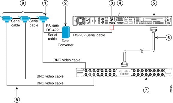
•![]() To connect multiple PTZ analog cameras, use a Cisco data converter to convert the RS-232 serial signals to RS-485/RS-422, as shown in Figure E-12. Connect the RS-485/RS-422 serial cable to the first camera, and then connect additional cameras in a daisy-chain configuration.
To connect multiple PTZ analog cameras, use a Cisco data converter to convert the RS-232 serial signals to RS-485/RS-422, as shown in Figure E-12. Connect the RS-485/RS-422 serial cable to the first camera, and then connect additional cameras in a daisy-chain configuration.
After the serial and BNC cables are connected, configure the following:
•![]() Enter the server serial port settings using the Cisco Video Surveillance Management Console. See See Step 5 in the following procedure.
Enter the server serial port settings using the Cisco Video Surveillance Management Console. See See Step 5 in the following procedure.
•![]() Enter the analog camera PTZ settings using the Cisco Video Surveillance Operations Manager (VSOM). See Step 7 in the following procedure.
Enter the analog camera PTZ settings using the Cisco Video Surveillance Operations Manager (VSOM). See Step 7 in the following procedure.
Complete the following steps to connect and configure PTZ analog cameras:
Procedure
Step 1 ![]() Connect the BNC video cable, as described in "Connecting the Video Capture Card to the BNC Breakout Panel" section.
Connect the BNC video cable, as described in "Connecting the Video Capture Card to the BNC Breakout Panel" section.
Step 2 ![]() Connect an RS-232 serial port adapter to the serial port on the Multiservices Platform Series.
Connect an RS-232 serial port adapter to the serial port on the Multiservices Platform Series.
The RS-232 adapter provides connections for individual serial cable wires. The RS-232 adapter is purchased separately and is not provided by Cisco.
Step 3 ![]() Connect a RS-232 serial cable to the RS-232 serial port adapter.
Connect a RS-232 serial cable to the RS-232 serial port adapter.
Step 4 ![]() Connect the PTZ analog camera(s):
Connect the PTZ analog camera(s):
•![]() Multiple Camera Configuration
Multiple Camera Configuration
Single Camera Configuration
If only one PTZ analog camera is used:
a. ![]() Connect a RS-232 cable from the COM (serial) port on the camera to the serial port adapter on the Multiservices Platform Series, as shown in Figure E-11.
Connect a RS-232 cable from the COM (serial) port on the camera to the serial port adapter on the Multiservices Platform Series, as shown in Figure E-11.
|
Note |
b. ![]() Connect the BNC video cable between the camera and the BNC breakout panel.
Connect the BNC video cable between the camera and the BNC breakout panel.
c. ![]() Continue to Step 5.
Continue to Step 5.
Figure E-11 Single Analog PTZ Camera: Serial and BNC Cable Connections

Multiple Camera Configuration
To connect multiple cameras, you must use a Cisco data converter to convert the RS-232 serial signals to RS-485/RS-422. Multiple cameras are only supported with RS-485/RS-422 serial connections.
Figure E-12 summarizes the cable connections in a multi-camera configuration.
Figure E-12 Multiple Analog PTZ Camera: Serial and BNC Cable Connections
|
|
First analog PTZ camera in the daisy-chain. |
|
Multi-channel video cable. |
|
|
Data converter to convert RS-232 serial signals to RS-485/RS-422 (see Figure E-13). |
|
BNC breakout panel. |
|
|
RS-232 serial port on the 1-RU or 2-RU Multiservices Platform Series. |
|
BNC video cables connected between each camera and the BNC breakout panel. |
|
|
Serial cable adapter used to connect individual RS-232 wires from the camera (see Figure E-13). |
|
Additional analog cameras connected with serial cables in a daisy-chain configuration. |
|
|
16 x D1 and 8 x D1 video capture cards installed in a Multiservices Platform Series. |
To connect multiple PTZ analog cameras, complete the following steps:
a. ![]() Connect a RS-232 serial cable between the DB-9 serial connector on the server and the Cisco data converter (Figure E-13).
Connect a RS-232 serial cable between the DB-9 serial connector on the server and the Cisco data converter (Figure E-13).
Figure E-13 Serial Port Pinouts for the Cisco Data Converter
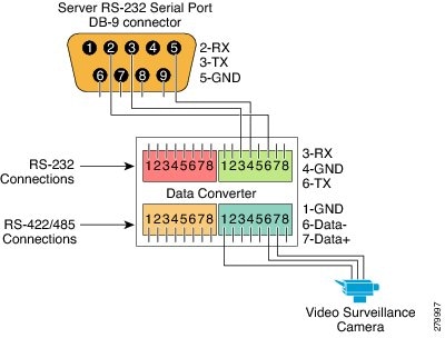
The RS-232 connections are:
|
|
|
2-RX connects to |
6-TX |
3-TX connects to |
3-RX |
5-GND connects to |
4-GND |
|
Tip |
b. ![]() Connect a RS-485 or RS-422 serial cable between the data converter and the first analog camera in the daisy-chain (Figure E-13).
Connect a RS-485 or RS-422 serial cable between the data converter and the first analog camera in the daisy-chain (Figure E-13).
See the camera documentation for connection instructions. Serial port connections vary by camera and manufacturer.
c. ![]() Connect an additional RS-485/RS-422 serial cable between the COM port on the first PTZ camera to the COM port on the second PTZ camera, as shown in Figure E-12.
Connect an additional RS-485/RS-422 serial cable between the COM port on the first PTZ camera to the COM port on the second PTZ camera, as shown in Figure E-12.
|
Note |
d. ![]() Continue to connect additional RS-485/RS-422 serial cables between the PTZ cameras in a daisy-chain configuration, as shown in Figure E-12.
Continue to connect additional RS-485/RS-422 serial cables between the PTZ cameras in a daisy-chain configuration, as shown in Figure E-12.
e. ![]() Connect BNC cables between each camera and the BNC breakout panel (Figure E-12).
Connect BNC cables between each camera and the BNC breakout panel (Figure E-12).
Step 5 ![]() Configure the server serial port using the Cisco Video Surveillance Management Console, as follows:
Configure the server serial port using the Cisco Video Surveillance Management Console, as follows:
a. ![]() Log in to the Video Surveillance Management Console using one of the options that is described in the "Using the VSM Management Console" chapter in Cisco Video Surveillance Operations Manager User Guide.
Log in to the Video Surveillance Management Console using one of the options that is described in the "Using the VSM Management Console" chapter in Cisco Video Surveillance Operations Manager User Guide.
b. ![]() Click Serial Port Configuration under the Configuration heading in the left menu.
Click Serial Port Configuration under the Configuration heading in the left menu.
|
Note |
c. ![]() Click Configure New Serial Port.
Click Configure New Serial Port.
d. ![]() From the Port drop-down menu choose COM1.
From the Port drop-down menu choose COM1.
e. ![]() Configure the following serial port settings to match the values the PTZ camera requires:
Configure the following serial port settings to match the values the PTZ camera requires:
–![]() Speed—Speed of the port, in bps
Speed—Speed of the port, in bps
–![]() Parity—Parity of the port (none, even or odd)
Parity—Parity of the port (none, even or odd)
–![]() Data Bits
Data Bits
–![]() Number of stop bits—1 or 2
Number of stop bits—1 or 2
|
Note |
f. ![]() Click the Add button.
Click the Add button.
A new row for the port that you configured appears.
|
Tip |
Step 6 ![]() If multiple cameras are attached in a daisy-chain configuration, configure the daisy-chain number on each camera according to the documentation that is included with the camera.
If multiple cameras are attached in a daisy-chain configuration, configure the daisy-chain number on each camera according to the documentation that is included with the camera.
Step 7 ![]() Use the Cisco VSOM pages to enter the PTZ settings for the camera.
Use the Cisco VSOM pages to enter the PTZ settings for the camera.
a. ![]() Log in to Cisco VSOM as described in the "Overview" chapter of Cisco Video Surveillance Operations Manager User Guide.
Log in to Cisco VSOM as described in the "Overview" chapter of Cisco Video Surveillance Operations Manager User Guide.
b. ![]() Click the Admin control link.
Click the Admin control link.
c. ![]() Click Analog Cameras.
Click Analog Cameras.
d. ![]() Choose a camera name for an existing configuration, or click Add a New Analog Camera.
Choose a camera name for an existing configuration, or click Add a New Analog Camera.
e. ![]() Choose the PTZ Config tab.
Choose the PTZ Config tab.
f. ![]() Choose the Camera is PTZ enabled check box to enable the settings.
Choose the Camera is PTZ enabled check box to enable the settings.
g. ![]() Choose COM1 from the COM Port drop-down menu.
Choose COM1 from the COM Port drop-down menu.
h. ![]() Enter the Chain Number for the camera. This is the number configured on the camera in Step 6.
Enter the Chain Number for the camera. This is the number configured on the camera in Step 6.
Troubleshooting PTZ Camera Controls
If the PTZ controls on an analog camera do not operate properly, review the physical connections and software configurations. Each connection and setting must be correct for the PTZ controls to operate.
•![]() Verify that the COM (serial) port is properly configured on the server. See Step 5 in the "Connecting and Configuring Analog PTZ Cameras" section.
Verify that the COM (serial) port is properly configured on the server. See Step 5 in the "Connecting and Configuring Analog PTZ Cameras" section.
•![]() Verify that the COM (serial) port settings entered in the Cisco Video Surveillance Management Console are the same as the settings on the camera.
Verify that the COM (serial) port settings entered in the Cisco Video Surveillance Management Console are the same as the settings on the camera.
–![]() See the camera documentation for the correct settings.
See the camera documentation for the correct settings.
–![]() See Step 5 in the "Connecting and Configuring Analog PTZ Cameras" section for information about entering the configuration on the Cisco Video Surveillance Management Console.
See Step 5 in the "Connecting and Configuring Analog PTZ Cameras" section for information about entering the configuration on the Cisco Video Surveillance Management Console.
•![]() Verify that the serial wiring connections to the camera and to the server serial port are correct. See the camera documentation for the correct wiring.
Verify that the serial wiring connections to the camera and to the server serial port are correct. See the camera documentation for the correct wiring.
•![]() Verify that the correct Chain Number for the PTZ camera is entered in the Cisco Video Surveillance Operations Manager.
Verify that the correct Chain Number for the PTZ camera is entered in the Cisco Video Surveillance Operations Manager.
•![]() Verify that the camera can be controlled independently by using PTZ controls.
Verify that the camera can be controlled independently by using PTZ controls.
•![]() If multiple cameras are connected in a daisy-chain:
If multiple cameras are connected in a daisy-chain:
–![]() Connect only a single camera and verify PTZ functionality. If the camera is functional, add and verify one additional camera at a time.
Connect only a single camera and verify PTZ functionality. If the camera is functional, add and verify one additional camera at a time.
–![]() Verify that the serial port settings are the same for all cameras in the daisy-chain.
Verify that the serial port settings are the same for all cameras in the daisy-chain.
Related Documentation
For information about configuring cameras that are attached to the 16 x D1 and 8 x D1 video capture cards, see the "Managing Analog Cameras" and the "Managing Camera Feeds" sections in Cisco Video Surveillance Manager User Guide.
 Feedback