Cisco Intrusion Prevention System Appliance and Module Installation Guide for IPS 5.1
Bias-Free Language
The documentation set for this product strives to use bias-free language. For the purposes of this documentation set, bias-free is defined as language that does not imply discrimination based on age, disability, gender, racial identity, ethnic identity, sexual orientation, socioeconomic status, and intersectionality. Exceptions may be present in the documentation due to language that is hardcoded in the user interfaces of the product software, language used based on RFP documentation, or language that is used by a referenced third-party product. Learn more about how Cisco is using Inclusive Language.
- Updated:
- November 17, 2006
Chapter: Installing NM-CIDS
Installing NM-CIDS
This chapter lists the software and hardware requirements of NM-CIDS, and describes how to install and remove it.

Note ![]() In Cisco IOS documentation, NM-CIDS is referred to as the Cisco IDS network module.
In Cisco IOS documentation, NM-CIDS is referred to as the Cisco IDS network module.
Note ![]() NM-CIDS does not support inline (IPS) mode. It can only be configured for promiscuous (IDS) mode.
NM-CIDS does not support inline (IPS) mode. It can only be configured for promiscuous (IDS) mode.

This chapter contains the following sections:
•![]() Software and Hardware Requirements
Software and Hardware Requirements
•![]() Installation and Removal Instructions
Installation and Removal Instructions
Specifications
Table 9-1 lists the specifications for NM-CIDS.
Software and Hardware Requirements
NM-CIDS has the following software and hardware requirements.
NM-CIDS supports the following software:
•![]() Cisco IOS software 12.2(15)ZJ or later
Cisco IOS software 12.2(15)ZJ or later
•![]() Cisco IOS software 12.3(4)T or later
Cisco IOS software 12.3(4)T or later
•![]() Cisco IDS software 4.1 or later
Cisco IDS software 4.1 or later
NM-CIDS supports the following feature sets:
•![]() IOS IP/FW/IDS
IOS IP/FW/IDS
•![]() IOS IP/FW/IDS PLUS IPSEC 56
IOS IP/FW/IDS PLUS IPSEC 56
•![]() IOS IP/FW/IDS PLUS IPSEC 3DES
IOS IP/FW/IDS PLUS IPSEC 3DES
•![]() IOS IP/IPX/AT/DEC/FW/IDS PLUS
IOS IP/IPX/AT/DEC/FW/IDS PLUS
•![]() IOS ENTERPRISE/FW/IDS PLUS IPSEC 56
IOS ENTERPRISE/FW/IDS PLUS IPSEC 56
•![]() IOS ENTERPRISE/FW/IDS PLUS IPSEC 3DES
IOS ENTERPRISE/FW/IDS PLUS IPSEC 3DES
•![]() IOS Advanced Security
IOS Advanced Security
•![]() IOS Advanced IP
IOS Advanced IP
•![]() IOS Advanced Enterprise
IOS Advanced Enterprise
Table 9-2 lists supported and unsupported platforms for NM-CIDS.
Note ![]() The supported Cisco series routers only support one NM-CIDS per chassis.
The supported Cisco series routers only support one NM-CIDS per chassis.
Table 9-3 lists the hardware specifications for NM-CIDS.
|
|
|
|---|---|
Processor |
500 Mhz Intel Mobile Pentium III |
Default SDRAM |
512 MB |
Maximum DSRAM |
512 MB |
Internal disk storage |
NM-CIDS 20-GB IDE |
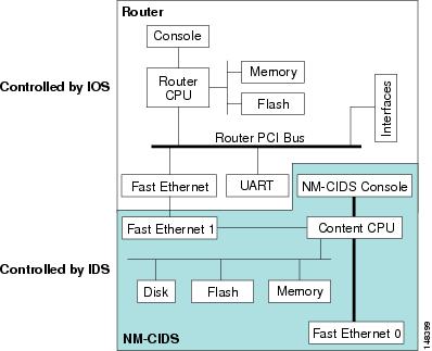
Hardware Architecture
NM-CIDS has the following hardware architecture:
•![]() Back-to-back Ethernet, which provides interface-level connectivity to the router.
Back-to-back Ethernet, which provides interface-level connectivity to the router.
•![]() 100-Mbps full-duplex interface between the router and the module.
100-Mbps full-duplex interface between the router and the module.
•![]() Back-to-back UART, which provides console access from router side.
Back-to-back UART, which provides console access from router side.
•![]() Console access to the module from the router.
Console access to the module from the router.
•![]() External FE interface, which provides a command and control interface.
External FE interface, which provides a command and control interface.
Figure 9-1 shows the hardware architecture of NM-CIDS.
Figure 9-1 NM-CIDS Hardware Architecture
Front Panel Features
Figure 9-2 shows the front panel features of the NM-CIDS.
Figure 9-2 Front Panel Features
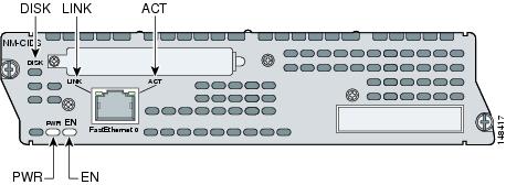
Table 9-4 describes the NM-CIDS states as indicated by the status indicators.
Interfaces
The router-side fast ethernet interface is known as "interface IDS-Sensor." This interface name appears in the show interface and show controller commands. You must assign the IP address to the interface to get console access to IDS.
For the procedure for assigning the IP address to gain access to the console and for setting up a loopback address, refer to Configuring IDS-Interfaces on the Router.
Installation and Removal Instructions
You must install NM-CIDS offline in Cisco 2650XM, 2651XM, and 2961 series routers.
Cisco 3660 and Cisco 3700 series routers lets you replace network modules without switching off the router or affecting the operation of other interfaces. OIR provides uninterrupted operation to network users, maintains routing information, and ensures session preservation.
Note ![]() Cisco 2600, 3600, and 3700 series routers support only one NM-CIDS per chassis.
Cisco 2600, 3600, and 3700 series routers support only one NM-CIDS per chassis.
This section contains the following topics:
Required Tools
You need the following tools and equipment to install NM-CIDS in a Cisco modular router chassis slot:
•![]() #1 Phillips screwdriver or small flat-blade screwdriver
#1 Phillips screwdriver or small flat-blade screwdriver
•![]() ESD-preventive wrist strap
ESD-preventive wrist strap
•![]() Tape for DC circuit breaker handle
Tape for DC circuit breaker handle
Installing NM-CIDS
This section describes how to install NM-CIDS off line and using OIR support, and contains the following topics:
•![]() Installing NM-CIDS Using OIR Support
Installing NM-CIDS Using OIR Support
Installing NM-CIDS Offline
You can install NM-CIDS in the chassis either before or after mounting the router, whichever is more convenient.
To install NM-CIDS, follow these steps:
Step 1 ![]() Turn OFF electrical power to the router.
Turn OFF electrical power to the router.
To channel ESD voltages to ground, do not unplug the power cable.
Step 2 ![]() Remove all network interface cables, including telephone cables, from the back panel.
Remove all network interface cables, including telephone cables, from the back panel.
Step 3 ![]() Using either a #1 Phillips screwdriver or a small flat-blade screwdriver, remove the blank filler panel from the chassis slot where you plan to install NM-CIDS.
Using either a #1 Phillips screwdriver or a small flat-blade screwdriver, remove the blank filler panel from the chassis slot where you plan to install NM-CIDS.
Save the blank panel for future use.
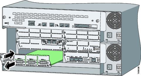
Step 4 ![]() Align NM-CIDS with the guides in the chassis and slide it gently into the slot.
Align NM-CIDS with the guides in the chassis and slide it gently into the slot.
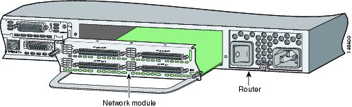
Step 5 ![]() Push NM-CIDS into place until you feel its edge connector mate securely with the connector on the motherboard.
Push NM-CIDS into place until you feel its edge connector mate securely with the connector on the motherboard.
Step 6 ![]() Fasten the captive mounting screws of NM-CIDS into the holes in the chassis, using a Phillips or flat-blade screwdriver.
Fasten the captive mounting screws of NM-CIDS into the holes in the chassis, using a Phillips or flat-blade screwdriver.
Step 7 ![]() If the router was previously running, reinstall the network interface cables and turn ON power to the router.
If the router was previously running, reinstall the network interface cables and turn ON power to the router.
The following warning applies to routers that use a DC power supply:
 |
Warning |
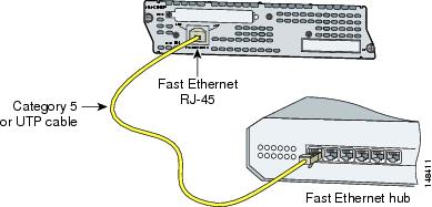
Step 8 ![]() Connect the command and control port to a hub or switch.
Connect the command and control port to a hub or switch.
Step 9 ![]() Check that NM-CIDS indicators light up, and that the Active/Ready indicators on the front panel also light up.
Check that NM-CIDS indicators light up, and that the Active/Ready indicators on the front panel also light up.
Step 10 ![]() Initialize NM-CIDS.
Initialize NM-CIDS.
For the procedure, see Initializing the Sensor.
Step 11 ![]() Upgrade NM-CIDS to the most recent Cisco software.
Upgrade NM-CIDS to the most recent Cisco software.
For the procedure, see Obtaining Cisco IPS Software.
You are now ready to configure intrusion detection on NM-CIDS.
For More Information
•![]() For the procedure for using HTTPS to log in to IDM, refer to Logging In to IDM.
For the procedure for using HTTPS to log in to IDM, refer to Logging In to IDM.
•![]() For the procedures for configuring intrusion detection on your sensor, refer to the following documents:
For the procedures for configuring intrusion detection on your sensor, refer to the following documents:
–![]() Installing and Using Cisco Intrusion Prevention System Device Manager 5.1
Installing and Using Cisco Intrusion Prevention System Device Manager 5.1
–![]() Configuring the Cisco Intrusion Prevention System Sensor Using the Command Line Interface 5.1
Configuring the Cisco Intrusion Prevention System Sensor Using the Command Line Interface 5.1
Installing NM-CIDS Using OIR Support
To install NM-CIDS using OIR support, follow these steps:
Step 1 ![]() Align NM-CIDS with the guides in the chassis slot and slide it gently into the slot.
Align NM-CIDS with the guides in the chassis slot and slide it gently into the slot.
Step 2 ![]() Push NM-CIDS into place until you feel its edge connector mate securely with the connector on the backplane.
Push NM-CIDS into place until you feel its edge connector mate securely with the connector on the backplane.
Step 3 ![]() Tighten the two captive screws on the faceplate.
Tighten the two captive screws on the faceplate.
Step 4 ![]() Connect the command and control port to a hub or switch.
Connect the command and control port to a hub or switch.
Step 5 ![]() Verify that NM-CIDS indicators light up, and that the Active/Ready indicators on the front panel also light up.
Verify that NM-CIDS indicators light up, and that the Active/Ready indicators on the front panel also light up.
Step 6 ![]() Initialize NM-CIDS.
Initialize NM-CIDS.
For the procedure, see Initializing the Sensor.
Step 7 ![]() Upgrade NM-CIDS to the most recent Cisco IPS software.
Upgrade NM-CIDS to the most recent Cisco IPS software.
For the procedure, see Obtaining Cisco IPS Software.
You are now ready to configure intrusion detection on NM-CIDS.
Removing NM-CIDS
This section describes how to remove NM-CIDS offline or using OIR support and contains the following topics:
•![]() Removing NM-CIDS Using OIR Support
Removing NM-CIDS Using OIR Support
Removing NM-CIDS Offline
You must turn off all power to the router before removing NM-CIDS.
To remove NM-CIDS from the router chassis, follow these steps:
Step 1 ![]() Prepare NM-CIDS to be powered off:
Prepare NM-CIDS to be powered off:
router# service-module IDS-Sensor slot_number/0 shutdown
Trying 10.10.10.1, 2129 ... Open
Wait for the shutdown message before continuing with Step 2:
%SERVICEMODULE-5-SHUTDOWN2:Service module IDS-Sensor1/0 shutdown complete
Step 2 ![]() Turn OFF electrical power to the router.
Turn OFF electrical power to the router.
To channel ESD voltages to ground, do not unplug the power cable.
Step 3 ![]() Unplug the command and control network interface cable from NM-CIDS.
Unplug the command and control network interface cable from NM-CIDS.
Step 4 ![]() Loosen the two captive screws holding NM-CIDS in the chassis slot.
Loosen the two captive screws holding NM-CIDS in the chassis slot.
Step 5 ![]() Slide NM-CIDS out of the slot.
Slide NM-CIDS out of the slot.
Note ![]() Either install a replacement NM-CIDS (for the procedure, see Installing NM-CIDS Offline) or install a blank panel (for the procedure, see Blank Network Module Panels).
Either install a replacement NM-CIDS (for the procedure, see Installing NM-CIDS Offline) or install a blank panel (for the procedure, see Blank Network Module Panels).
Removing NM-CIDS Using OIR Support
To remove NM-CIDS with OIR support, follow these steps:
Step 1 ![]() Prepare NM-CIDS to be powered off:
Prepare NM-CIDS to be powered off:
router# service-module IDS-Sensor slot_number/0 shutdown
Trying 10.10.10.1, 2129 ... Open
Wait for the shutdown message before continuing with Step 2:
%SERVICEMODULE-5-SHUTDOWN2:Service module IDS-Sensor1/0 shutdown complete
Step 2 ![]() Unplug the command and control network interface cable from NM-CIDS.
Unplug the command and control network interface cable from NM-CIDS.
Step 3 ![]() Loosen the two captive screws holding NM-CIDS in the chassis slot.
Loosen the two captive screws holding NM-CIDS in the chassis slot.
Step 4 ![]() Slide NM-CIDS out of the slot.
Slide NM-CIDS out of the slot.
Note ![]() Either install a replacement NM-CIDS (for the procedure, see Installing NM-CIDS Using OIR Support), or install a blank panel (for the procedure, see Blank Network Module Panels).
Either install a replacement NM-CIDS (for the procedure, see Installing NM-CIDS Using OIR Support), or install a blank panel (for the procedure, see Blank Network Module Panels).
Blank Network Module Panels
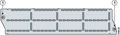
If the router is not fully configured with network modules, make sure that blank panels fill the unoccupied chassis slots to provide proper airflow as shown in Figure 9-3.
Figure 9-3 Blank Network Module Panel
 Feedback